Eclipse Engineering Guide
Eclipse Engineering Guide
Eclipse Engineering Guide
You also want an ePaper? Increase the reach of your titles
YUMPU automatically turns print PDFs into web optimized ePapers that Google loves.
II. Spray Washers<br />
Three methods are presented for calculating spray<br />
washer heat requirements. The first is the most accurate,<br />
making use of detailed heat loss factors. The<br />
other two are rule-of-thumb methods. While not as<br />
accurate as method A, they are useful for quickly<br />
estimating burner inputs.<br />
A. Heat Loss Method<br />
1.Data required:<br />
Gpm capacity of spray nozzles<br />
Height & width of washer housing (hood)<br />
Height & width of opening through which<br />
work passes<br />
Liquid pressure head<br />
Liquid temperature<br />
Location of stage in washer<br />
2.Heat Loss factors<br />
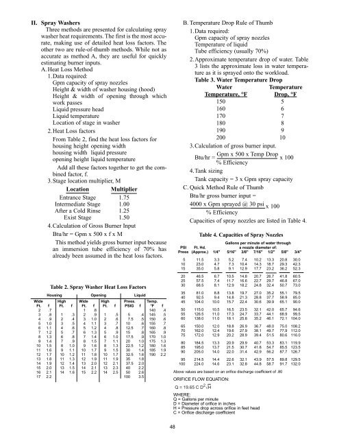
From Table 2, find the heat loss factors for<br />
housing height opening width<br />
housing width liquid pressure<br />
opening height liquid temperature<br />
Add all these factors together to get the combined<br />
factor, f.<br />
3.Stage location multiplier, M<br />
Location Multiplier<br />
Entrance Stage 1.75<br />
Intermediate Stage 1.00<br />
After a Cold Rinse 1.25<br />
Exist Stage 1.50<br />
4.Calculation of Gross Burner Input<br />
Btu/hr = Gpm x 500 x f x M<br />
This method yields gross burner input because<br />
an immersion tube efficiency of 70% has<br />
already been assumed in the heat loss factors.<br />
Table 2. Spray Washer Heat Loss Factors<br />
Housing Opening Liquid<br />
Wide High Wide High Press. Temp.<br />
Ft. f Ft. f Ft. f Ft. f PSIG f °F f<br />
2 .7 1 .8 140 .4<br />
3 .8 1 .3 2 .9 1 .5 5 .4 145 .5<br />
4 .9 2 .4 3 1.0 2 .6 7.5 .5 150 .6<br />
5 1.0 3 .5 4 1.1 3 .7 10 .6 155 .7<br />
6 1.1 4 .6 5 1.2 4 .8 12.5 .7 160 .8<br />
7 1.2 5 .7 6 1.3 5 .9 15 .8 165 .9<br />
8 1.3 6 .8 7 1.4 6 1.0 17.5 .9 170 1.0<br />
9 1.4 7 .9 8 1.5 7 1.1 20 1.0 175 1.3<br />
10 1.5 8 1.0 9 1.6 8 1.3 22.5 1.2 180 1.6<br />
11 1.6 9 1.1 10 1.7 9 1.5 30 1.4 185 1.9<br />
12 1.7 10 1.2 11 1.8 10 1.7 32.5 1.6 190 2.2<br />
13 1.8 11 1.3 12 1.9 11 1.9 35 1.8<br />
14 1.9 12 1.4 13 2.0 12 2.1 37.5 2.0<br />
15 2.0 13 1.5 14 2.1 13 2.3 40 2.2<br />
16 2.1 14 1.6 15 2.2 14 2.5 50 2.6<br />
17 2.2 100 3.5<br />
48<br />
B. Temperature Drop Rule of Thumb<br />
1.Data required:<br />
Gpm capacity of spray nozzles<br />
Temperature of liquid<br />
Tube efficiency (usually 70%)<br />
2.Approximate temperature drop of water. Table<br />
3 lists the approximate loss in water temperature<br />
as it is sprayed onto the workload.<br />
Table 3. Water Temperature Drop<br />
Water Temperature<br />
Temperature, °F Drop, °F<br />
150 5<br />
160 6<br />
170 7<br />
180 8<br />
190 9<br />
200 10<br />
3.Calculation of gross burner input.<br />
Btu/hr = Gpm x 500 x Temp Drop x 100<br />
% Efficiency<br />
4.Tank sizing<br />
Tank capacity = 3 x Gpm spray capacity<br />
C. Quick Method Rule of Thumb<br />
Btu/hr gross burner input =<br />
4000 x Gpm sprayed @ 30 psi x 100<br />
% Efficiency<br />
Capacities of spray nozzles are listed in Table 4.<br />
Table 4. Capacities of Spray Nozzles<br />
PSI Ft. Hd.<br />
Gallons per minute of water through<br />
a nozzle diameter of:<br />
Press (Approx.) 1/4" 5/16" 3/8" 7/16" 1/2" 5/8" 3/4"<br />
5 11.5 3.3 5.2 7.4 10.2 13.3 20.8 30.0<br />
10 23.0 4.7 7.3 10.4 14.3 18.7 29.3 42.3<br />
15 35.0 5.8 9.1 12.9 17.7 23.2 36.2 52.3<br />
20 46.5 6.7 10.5 14.8 20.7 26.7 41.8 60.5<br />
25 57.5 7.4 11.7 16.6 22.7 29.7 46.8 67.0<br />
30 68.5 8.1 12.9 18.2 24.8 32.4 50.7 73.0<br />
35 81.0 8.8 13.8 19.7 27.0 35.2 55.1 79.5<br />
40 92.5 9.4 14.8 21.3 28.8 37.7 58.9 85.0<br />
45 104.0 10.0 15.7 22.4 30.6 39.9 65.1 90.0<br />
50 115.0 10.5 16.5 23.5 32.1 42.0 65.7 94.6<br />
55 126.5 11.0 17.3 24.7 33.7 44.1 68.9 99.5<br />
60 138.0 11.0 18.1 25.8 35.2 46.1 72.1 104.0<br />
65 150.0 12.0 18.8 26.9 36.7 48.0 75.0 108.2<br />
70 162.0 12.4 19.6 27.9 38.1 49.7 77.9 112.0<br />
75 172.0 12.9 20.2 28.9 39.4 51.5 80.6 116.0<br />
80 184.5 13.3 20.9 29.9 40.7 53.3 83.1 119.9<br />
85 195.0 13.7 21.5 30.7 41.8 54.7 85.5 123.5<br />
90 205.0 14.0 22.0 31.4 42.9 56.2 87.7 126.7<br />
95 214.5 14.4 22.6 32.1 43.9 57.5 89.8 129.5<br />
100 224.0 14.6 23.1 32.8 44.8 58.7 91.7 132.0<br />
Above values are based on an orifice discharge coefficient of .80<br />
ORIFICE FLOW EQUATION:<br />
Q = 19.65 C D 2 H<br />
WHERE:<br />
Q = Gallons per minute<br />
D = Diameter of orifice in inches<br />
H = Pressure drop across orifice in feet head<br />
C = Orifice discharge coefficient


