Eclipse Engineering Guide
Eclipse Engineering Guide
Eclipse Engineering Guide

You also want an ePaper? Increase the reach of your titles
YUMPU automatically turns print PDFs into web optimized ePapers that Google loves.
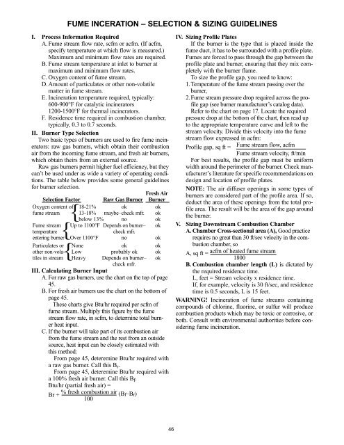
FUME INCERATION – SELECTION & SIZING GUIDELINES<br />
I. Process Information Required<br />
A. Fume stream flow rate, scfm or acfm. (If acfm,<br />
specify temperature at which flow is measured.)<br />
Maximum and minimum flow rates are required.<br />
B. Fume stream temperature at inlet to burner at<br />
maximum and minimum flow rates.<br />
C. Oxygen content of fume stream.<br />
D. Amount of particulates or other non-volatile<br />
matter in fume stream.<br />
E. Incineration temperature required, typically:<br />
600-900°F for catalytic incinerators<br />
1200-1500°F for thermal incinerators.<br />
F. Residence time required in combustion chamber,<br />
typically, 0.3 to 0.7 seconds.<br />
II. Burner Type Selection<br />
Two basic types of burners are used to fire fume incinerators:<br />
raw gas burners, which obtain their combustion<br />
air from the incoming fume stream, and fresh air burners,<br />
which obtain theirs from an external source.<br />
Raw gas burners permit higher fuel efficiency, but they<br />
can’t be used under as wide a variety of operating conditions.<br />
The table below provides some general guidelines<br />
for burner selection.<br />
Fresh Air<br />
Selection Factor Raw Gas Burner Burner<br />
Oxygen content of 18-21% ok ok<br />
fume stream 13-18% maybe–check mfr. ok<br />
below 13% no ok<br />
Fume stream Up to 1100°F Depends on burner– ok<br />
temperature check mfr.<br />
entering burner Over 1100°F no ok<br />
Particulates or None<br />
other non-vola- Low<br />
tiles in stream Heavy<br />
ok<br />
probably ok<br />
Depends on burner–<br />
ok<br />
ok<br />
ok<br />
check mfr.<br />
III. Calculating Burner Input<br />
A. For raw gas burners, use the chart on the top of page<br />
45.<br />
B. For fresh air burners use the chart on the bottom of<br />
page 45.<br />
These charts give Btu/hr required per scfm of<br />
fume stream. Multiply this figure by the fume<br />
stream flow rate, in scfm, to determine total burner<br />
heat input.<br />
C. If the burner will take part of its combustion air<br />
from the fume stream and the rest from an outside<br />
source, heat input can be closely estimated with<br />
this method:<br />
From page 45, deteremine Btu/hr required with<br />
a raw gas burner. Call this Br.<br />
From page 45, deteremine Btu/hr required with<br />
a 100% fresh air burner. Call this Bf.<br />
Btu/hr (partial fresh air) =<br />
Br + % fresh combustion air IV. Sizing Profile Plates<br />
If the burner is the type that is placed inside the<br />
fume duct, it has to be surrounded with a profile plate.<br />
Fumes are forced to pass through the gap between the<br />
profile plate and burner, ensuring that they mix completely<br />
with the burner flame.<br />
To size the profile gap, you need to know:<br />
1.Temperature of the fume stream passing over the<br />
burner,<br />
2.Fume stream pressure drop required across the profile<br />
gap (see burner manufacturer’s catalog data).<br />
Refer to the chart on page 17. Locate the required<br />
pressure drop at the bottom of the chart, then read up<br />
to the appropriate temperature curve and left to the<br />
stream velocity. Divide this velocity into the fume<br />
stream flow expressed in acfm:<br />
Profile gap, sq ft = Fume stream flow, acfm<br />
Fume stream velocity, ft/min<br />
For best results, the profile gap must be uniform<br />
width around the perimeter of the burner. Check manufacturer’s<br />
literature for specific recommendations on<br />
design and location of profile plates.<br />
{<br />
{<br />
V.<br />
NOTE: The air diffuser openings in some types of<br />
burners are considered part of the profile area. If so,<br />
deduct the area of these openings from the total profile<br />
area. The result will be the area of the gap around<br />
the burner.<br />
Sizing Downstream Combustion Chamber<br />
A. Chamber Cross-sectional area (A), Good practice<br />
requires no great than 30 ft/sec velocity in the com-<br />
{<br />
bustion chamber, so<br />
A, sq ft = acfm of heated fume stream<br />
1800<br />
B. Combustion chamber length (L) is dictated by<br />
(Bf–Br)<br />
100<br />
the required residence time.<br />
L, feet = Stream velocity x residence time.<br />
If, for example, velocity is 30 ft/sec, and residence<br />
time is 0.5 seconds, L is 15 feet.<br />
WARNING! Incineration of fume streams containing<br />
compounds of chlorine, fluorine, or sulfur will produce<br />
combustion products which may be toxic or corrosive, or<br />
both. Consult with environmental authorities before considering<br />
fume incineration.<br />
46