Max Charge MC-612-DUAL (Sept. 2009 - and - Balmar
Max Charge MC-612-DUAL (Sept. 2009 - and - Balmar
Max Charge MC-612-DUAL (Sept. 2009 - and - Balmar

Create successful ePaper yourself
Turn your PDF publications into a flip-book with our unique Google optimized e-Paper software.
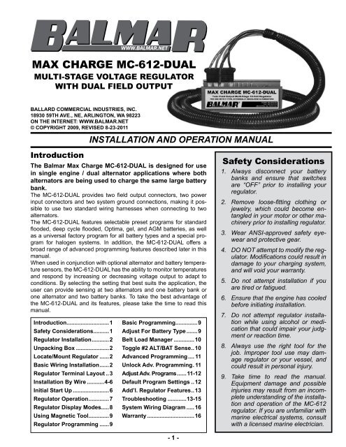
MAX CHARGE <strong>MC</strong>-<strong>612</strong>-<strong>DUAL</strong><br />
MULTI-STAGE VOLTAGE REGULATOR<br />
WITH <strong>DUAL</strong> FIELD OUTPUT<br />
BALLARD COMMERCIAL INDUSTRIES, INC.<br />
18930 59TH AVE., NE, ARLINGTON, WA 98223<br />
ON THE INTERNET: WWW.BALMAR.NET<br />
© COPYRIGHT <strong>2009</strong>, REVISED 8-23-2011<br />
Introduction<br />
INSTALLATION AND OPERATION MANUAL<br />
The <strong>Balmar</strong> <strong>Max</strong> <strong>Charge</strong> <strong>MC</strong>-<strong>612</strong>-<strong>DUAL</strong> is designed for use<br />
in single engine / dual alternator applications where both<br />
alternators are being used to charge the same large battery<br />
bank.<br />
The <strong>MC</strong>-<strong>612</strong>-<strong>DUAL</strong> provides two field output connectors, two power<br />
input connectors <strong>and</strong> two system ground connections, making it possible<br />
to use two st<strong>and</strong>ard wiring harnesses when connecting to two<br />
alternators.<br />
The <strong>MC</strong>-<strong>612</strong>-<strong>DUAL</strong> features selectable preset programs for st<strong>and</strong>ard<br />
flooded, deep cycle flooded, Optima, gel, <strong>and</strong> AGM batteries, as well<br />
as a universal factory program for all battery types <strong>and</strong> a special program<br />
for halogen systems. In addition, the <strong>MC</strong>-<strong>612</strong>-<strong>DUAL</strong> offers a<br />
broad range of advanced programming features described later in this<br />
manual.<br />
When used in conjunction with optional alternator <strong>and</strong> battery temperature<br />
sensors, the <strong>MC</strong>-<strong>612</strong>-<strong>DUAL</strong> has the ability to monitor temperatures<br />
<strong>and</strong> respond by increasing or decreasing voltage output to adapt to<br />
conditions. By selecting the setting that best suits the application, the<br />
user can provide sensing at two alternators <strong>and</strong> one battery bank or<br />
one alternator <strong>and</strong> two battery banks. To take the best advantage of<br />
the <strong>MC</strong>-<strong>612</strong>-<strong>DUAL</strong> <strong>and</strong> its features, please take the time to read this<br />
manual.<br />
Introduction ...........................1<br />
Safety Considerations..........1<br />
Regulator Installation ...........2<br />
Unpacking Box .....................2<br />
Locate/Mount Regulator ......2<br />
Basic Wiring Installation ......2<br />
Regulator Terminal Layout ..3<br />
Installation By Wire ...........4-6<br />
Initial Start Up .......................6<br />
Regulator Operation .............7<br />
Regulator Display Modes.....8<br />
Using Magnetic Tool .............9<br />
Regulator Programming ......9<br />
Basic Programming..............9<br />
Adjust For Battery Type .......9<br />
Belt Load Manager .............10<br />
Toggle #2 ALT/BAT Sense ..10<br />
Advanced Programming .... 11<br />
Unlock Adv. Programming . 11<br />
Adjust Adv. Programs ......11-12<br />
Default Program Settings ..12<br />
Add’l. Regulator Features ..13<br />
Troubleshooting ............13-15<br />
System Wiring Diagram .....16<br />
Warranty ..............................16<br />
- 1 -<br />
Safety Considerations<br />
1.<br />
2.<br />
3.<br />
4.<br />
5.<br />
6.<br />
7.<br />
8.<br />
9.<br />
Always disconnect your battery<br />
banks <strong>and</strong> ensure that switches<br />
are “OFF” prior to installing your<br />
regulator.<br />
Remove loose-fitting clothing or<br />
jewelry, which could become entangled<br />
in your motor or other machinery<br />
prior to installing regulator.<br />
Wear ANSI-approved safety eyewear<br />
<strong>and</strong> protective gear.<br />
DO NOT attempt to modify the regulator.<br />
Modifications could result in<br />
damage to your charging system,<br />
<strong>and</strong> will void your warranty.<br />
Do not attempt installation if you<br />
are tired or fatigued.<br />
Ensure that the engine has cooled<br />
before initiating installation.<br />
Do not attempt regulator installation<br />
while using alcohol or medication<br />
that could impair your judgment<br />
or reaction time.<br />
Always use the right tool for the<br />
job. Improper tool use may damage<br />
regulator or your vessel, <strong>and</strong><br />
could result in personal injury.<br />
Take time to read the manual.<br />
Equipment damage <strong>and</strong> possible<br />
injuries may result from an incomplete<br />
underst<strong>and</strong>ing of the installation<br />
<strong>and</strong> operation of the <strong>MC</strong>-<strong>612</strong><br />
regulator. If you are unfamiliar with<br />
marine electrical systems, consult<br />
with a licensed marine electrician.
CAUTIOn: The <strong>Balmar</strong> <strong>Max</strong> <strong>Charge</strong> <strong>MC</strong>-<strong>612</strong>-<strong>DUAL</strong> is designed for use in single engine,<br />
dual alternator applications where both alternators are being used to charge the same large<br />
battery bank. The following instructions are intended for use by experienced marine electrical<br />
installers. If you are not experienced at installing electrical system components, we<br />
recommend the use of a qualified marine electrical technician.<br />
Regulator Installation<br />
The following information is intended to provide the installer with the<br />
basic information required to complete installation. This section of the<br />
installation manual will deal with mounting, wiring connections <strong>and</strong> basic<br />
programming for battery type. Additional information regarding advanced<br />
programming adjustments <strong>and</strong> troubleshooting are addressed<br />
later in the manual.<br />
Unpacking The Box<br />
Your <strong>Max</strong> <strong>Charge</strong> <strong>MC</strong>-<strong>612</strong>-<strong>DUAL</strong>-H regulator kit is packaged with the<br />
following items:<br />
• <strong>Max</strong> <strong>Charge</strong> <strong>MC</strong>-<strong>612</strong>-<strong>DUAL</strong> regulator<br />
• (2) 54” wiring harnesses w/ 10A-fused 12 Ga. RED power wires<br />
• Fused (1A) battery sense wire pigtail<br />
• Magnetic programming tool<br />
•<br />
Installation <strong>and</strong> operation manual<br />
If any of the listed items is not included with your regulator kit, call our<br />
customer service department at 360-435-6100. Please note -- if your regulator box is marked <strong>Max</strong> <strong>Charge</strong> <strong>MC</strong>-<strong>612</strong>, without<br />
the “H” designation, your kit will not include the wiring harnesses or fused battery sense pigtail.<br />
Locate And Mount The Regulator<br />
Choosing a mounting location for your voltage regulator should be determined<br />
based on the following factors; distance from alternator, distance from<br />
inverters, transmitters <strong>and</strong> other sources of RF noise, convenient access<br />
<strong>and</strong> readability of the display. The regulator wiring harness is 54 inches long,<br />
providing a three to four foot radius for mounting. Ample airflow is essential<br />
for the regulator’s proper operation. Ensure that the regulator is free from<br />
obstructions that restrict air movement around or below the regulator’s aluminum<br />
heat sink. While the regulator is designed to operate safely in conditions<br />
typical of a marine engine compartment, the regulator may be better<br />
protected, <strong>and</strong> easier to use <strong>and</strong> monitor if mounted outside of the engine<br />
compartment.<br />
Should it be necessary to install the regulator further than the harness’s 54”<br />
length from the alternator, ensure that any wire extensions are properly connected,<br />
as resistance in the harness wiring can affect charging efficiency.<br />
If harness length must reach beyond approximately eight feet, replace the<br />
RED power <strong>and</strong> BLUE field wires with larger gauge wire that’s sized to<br />
ensure voltage drop < 3%..<br />
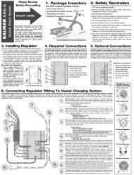
Basic Wiring Installation<br />
The regulator’s wiring harness includes six wires required for st<strong>and</strong>ard<br />
installation. Four of those wires are connected to the regulator via a<br />
Ford-style plug connector that’s pre-installed on the regulator. These<br />
wires include the Ground (BLACK), Power (RED), Ignition (BROWN)<br />
<strong>and</strong> Field (BLUE). Plug is shown at right.<br />
In addition, the harness includes a separate Ground (BLACK) <strong>and</strong> Stator<br />
(WHITE) wire. The proper terminal connection points for these, <strong>and</strong><br />
additional wiring connections, are illustrated on the pin location legend<br />
shown <strong>and</strong> discussed on the following pages.<br />
The <strong>MC</strong>-<strong>612</strong>-<strong>DUAL</strong> is designed with parallel terminal locations for field,<br />
power <strong>and</strong> ground circuits, so two st<strong>and</strong>ard <strong>Balmar</strong> wiring harnesses<br />
can be used together.<br />
- 2 -
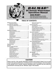
<strong>MC</strong>-<strong>612</strong>-<strong>DUAL</strong> Regulator Terminal Layout<br />
1. GROUND INPUT (ALTERNATOR #2) - Connects<br />
regulator to system ground via alternator ground terminal.<br />
BLACK wire included in Ford style plug.<br />
2. GROUND INPUT (ALTERNATOR #1) - Connects<br />
regulator to system ground via alternator ground terminal.<br />
Loose BLACK wire included in regulator wiring<br />
harness or to second wiring harness.<br />
3. POWER INPUT (ALTERNATOR #2) - Supplies power<br />
to operate the regulator <strong>and</strong> deliver field current to excite<br />
alternator. RED wire included in Ford-style plug.<br />
4. POWER INPUT (ALTERNATOR #1) - Supplies power<br />
to operate regulator <strong>and</strong> deliver field current to excite<br />
alternator. RED wire in second alternator harness.<br />
5. IGNITION INPUT (ALTERNATOR #1) - Connects to a<br />
switched source of battery voltage (to ignition switch<br />
or oil pressure switch. BROWN wire in regulator wiring<br />
harness.<br />
6. FIELD OUTPUT (ALTERNATOR #2) - Provides external<br />
(P-type) alternator field control for the secondary<br />
alternator. BLUE wire in secondary wiring harness.<br />
7. FIELD OUTPUT (ALTERNATOR #1) - Provides external<br />
(P-type) alternator field control for the primary<br />
alternator. BLUE wire in regulator wiring harness.<br />
8. ALT. TEMP. #1 (-) - For use with optional Alternator<br />
Temperature Sensor (<strong>MC</strong>-TS-A).<br />
9. ALT. TEMP. #1 (+) - For use with optional Alternator<br />
Temperature Sensor (<strong>MC</strong>-TS-A). Sensor lug connects<br />
to rear case bolt of alternator, enabling regulator to<br />
monitor <strong>and</strong> react to alternator over-temperature condition.<br />
USE CARE TO ENSURE COR-<br />
RECT PIN POLARITY WHEN CON-<br />
NECTING SENSOR CABLE TO THE<br />
REGULATOR.<br />
10. BAT. TEMP. #1 (-) - For use with optional<br />
Battery Temperature Sensor<br />
(<strong>MC</strong>-TS-B).<br />
11. BAT. TEMP. #1 (+) - For use with optional<br />
BATTERY Temperature Sensor<br />
(<strong>MC</strong>-TS-A). Sensor lug connects to<br />
negative battery post, enabling regulator<br />
to monitor <strong>and</strong> respond to battery<br />
temperature condition. USE CARE TO<br />
ENSURE POSITIVE AND NEGATIVE<br />
WIRES ARE CONNECTED TO THE<br />
APPROPRIATE REGULATOR TERMI-<br />
NAL.<br />
12. POSITIVE VOLTAGE SENSE - Connects<br />
to battery being charged. Use<br />
RED fused pigtail connector (included)<br />
at battery end of user-installed wire.<br />
The POSITIVE VOLTAGE SENSE wire<br />
MUST be connected for the regulator to<br />
work.<br />
- 3 -<br />
13. DATA RX (Factory use only).<br />
14. DATA TX (Factory use only).<br />
15. STATOR IN - Connect to WHITE wire included in regulator<br />
wiring harness.<br />
16. TACHOMETER OUT - Connect to tachometer sender<br />
wire when using stator output to provide a signal for<br />
an electric tachometer. NOT REQUIRED when a mechanical<br />
tachometer is used.<br />
17. ALT. #2 / BAT. #2 TEMP. (-) - For use with optional<br />
Alternator Temperature Sensor (<strong>MC</strong>-TS-A) or Battery<br />
Temperature Sensor (<strong>MC</strong>-TS-B).<br />
18. ALT. #2 / BAT. #2 TEMP. (+) - User selectable circuit<br />
can be used to temperature sense at a second alternator<br />
or a second battery bank. Requires either optional<br />
<strong>MC</strong>-TS-A or <strong>MC</strong>-TS-B sensor cable. USE CARE TO<br />
ENSURE POSITIVE AND NEGATIVE WIRES ARE<br />
CONNECTED TO THE APPROPRIATE REGULATOR<br />
TERMINAL.<br />
19. AUX. #1 LAMP - provides a source of ground under the<br />
following conditions: Full Field (the alternator is working<br />
at full power), Small Engine Mode (the regulator is<br />
being controlled at 50% field output), or Equalization<br />
Mode. Connect to negative terminal of audible alarm or<br />
lamp. 500 mA maximum.<br />
20. DASH LAMP - provides a source of ground under the<br />
following conditions: Low charging voltage (15.5V), high alternator temperature<br />
(>105°C), or high battery temperature (>52°C).<br />
500 mA maximum.<br />
6<br />
7<br />
5<br />
3<br />
4<br />
1<br />
2
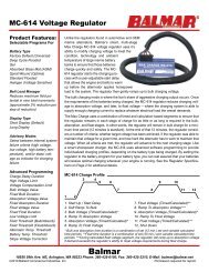
Installation By Wire<br />
Install BLACK Ground Wire(s)<br />
The BLACK Ground Wires (#1 <strong>and</strong> #2 in diagram at right) are included in the four-wire Ford-style plugs on the PRIMARY<br />
<strong>and</strong> SECONDARY wiring harnesses <strong>and</strong> are factory installed on regulator packages designated with “H” at the end of the<br />
model number. The other end of the Ground Wire is fitted with a ring terminal connector.<br />
In most applications, this wire can be connected directly to the alternator’s<br />
ground terminal post. Both alternators <strong>and</strong> regulators must be connected to system<br />
ground. Check continuity between primary <strong>and</strong> secondary alternator ground<br />
6<br />
terminals to ensure minimal resistance.<br />
Install RED Power Wire(s)<br />
7<br />
The RED Power Wires (#3 <strong>and</strong> #4 in diagram at right) are included in the four-wire<br />
5<br />
Ford-style plugs on the PRIMARY <strong>and</strong> SECONDARY wiring harnesses <strong>and</strong> are<br />
factory installed on regulator packages designated with “H” at the end of the model<br />
number. The other end of the Power Wire is fitted with a ring terminal connector.<br />
3<br />
In most applications, this wire can be connected directly to the alternator’s positive<br />
output post. When a diode-type battery isolator is used, the primary <strong>and</strong> secondary<br />
4<br />
power wires must be connected to the battery side of the battery isolator. Power<br />
Wires are equipped with 15-amp ATC type fusing. PRIMARY <strong>and</strong> SECONDARY<br />
1<br />
wires must be fused.<br />
Install BROWn Ignition Wire<br />
2<br />
The BROWN Ignition Wire (#5 in diagram at right) provides the ON/OFF voltage for<br />
the regulator. This wire is included in the Ford-style plug at the regulator end of the<br />
PRIMARY wiring harness. The other end of the wire is fitted with a butt connector.<br />
Typically, the ignition wire is connected to the ON side of the ignition switch. This<br />
may be at the actual switch, or to the wire in the existing engine wiring loom that<br />
delivers switched voltage from the ignition switch. In some cases, an oil pressure<br />
switch may be used to activate the regulator. In either case, the regulator’s ignition wire must see zero volts when the<br />
engine ignition is switched off. Only one ignition wire is required to activate the regulator.<br />
Install BLUE Field Wire(s)<br />
The BLUE Field Wires (#6 <strong>and</strong> #7 in diagram at right) provide regulated voltage to the alternators to excite the rotors <strong>and</strong><br />
stators <strong>and</strong> control alternator output. The wire is included in the wiring harness Ford-style plug <strong>and</strong> is pre-connected at<br />
the regulator. At the other end of the wire, you’ll find either a plug or a ring terminal, depending on the alternator’s field<br />
terminal connection. Attach the field wire to the alternator’s field terminal.<br />
Field wires should be equal in length. See your alternator manual for any<br />
specific requirements your alternator may have.<br />
Install Alternator #1 Temperature Sensor<br />
The optional Alternator Temperature Sensor (<strong>MC</strong>-TS-A) allows your <strong>Max</strong><br />
<strong>Charge</strong> voltage regulator to monitor your alternator for temperatures in excess<br />
of safe operating levels. The <strong>MC</strong>-TS-A sensor assmbly includes a 54”<br />
cable, a sensing attachment lug <strong>and</strong> positive <strong>and</strong> negative regulator plug-in<br />
connectors. To install the <strong>MC</strong>-TS-A:<br />
1. Connect the sensor lug to one of the four bolts that hold the alternator’s<br />
front <strong>and</strong> rear cases together. Extend sensor cable to the regulator. The<br />
cable can be included within the regulator’s wiring harness, or can be<br />
run alongside the harness <strong>and</strong> attached with cable ties.<br />
2. Connect the positive <strong>and</strong> negative female connectors to the Alternator<br />
Temp. Sense terminals on the regulator (#8 is NEGATIVE. #9 is<br />
POSITIVE). It is essential that the terminals match the polarity of the<br />
regulator connection pins (red wire to positive terminal <strong>and</strong> black wire<br />
to negative terminal).<br />
- 4 -
Install Battery #1 Temperature Sensor<br />
The optional Battery Temperature Sensor (<strong>MC</strong>-TS-B) enables the regulator<br />
to monitor for changes in ambient battery temperature, <strong>and</strong> adjust charging<br />
voltages to suit. The <strong>MC</strong>-TS-B sensor assmbly includes a 20-foot cable, a<br />
sensing attachment lug <strong>and</strong> positive <strong>and</strong> negative regulator plug-in connectors.<br />
To install the <strong>MC</strong>-TS-B:<br />
1. Connect the sensor lug to the battery negative post closest to the center<br />
of the battery bank. Extend sensor cable to the regulator<br />
2. Connect the positive <strong>and</strong> negative female connectors to the Battery<br />
temperature sensors on the regulator (#10 is NEGATIVE. #11 is POSI-<br />
TIVE). NOTE: Wire terminals must match the polarity of the regulator<br />
connection pins (red wire to positive terminal <strong>and</strong> black wire to negative<br />
terminal).<br />
Install Positive Battery Sense Wire<br />
Included with the <strong>MC</strong>-<strong>612</strong>’s wiring harness kit is a fused wiring pigtail which<br />
features a ring terminal at one end <strong>and</strong> a butt connector at the other. In the<br />
center is a 1-Amp ATC-type fuse <strong>and</strong> fuse holder. This wire must be connected<br />
at the #12 Positive Battery Sense terminal A female quick connect<br />
plug has been pre-attached on the terminal #12 pin. To complete installation<br />
of the sense circuit:<br />
1. Identify the favored location for battery sensing. In most instances, the<br />
positive output of the alternator, the common side of a battery switch, or the positive post of the battery being charged<br />
will work best. If the batteries are connected to a battery isolator, the positive sense wire must be connected to the<br />
battery side of the isolator, preferably at the larger of the battery banks.<br />
2. Attach the included wiring pigtail with 1-amp fuse to a length of wire of sufficient to reach from the regulator to the<br />
desired sensing location. If the length of the wire run between the regulator <strong>and</strong> the sensing location is 8’ or less, a<br />
16-gauge wire is satisfactory. If the wire run exceeds 8’, increase the wire size to 14 gauge.<br />
3. Remove the female 1/4” spade terminal from the terminal #12 pin. Crimp the spade terminal to the sense wire <strong>and</strong><br />
reconnect the spade to the #12 terminal pin.<br />
Data TX <strong>and</strong> RX Terminals (#13 <strong>and</strong> #14)<br />
Are currently for factory use only, <strong>and</strong> do not require connection at the regulator.<br />
Install WHITE Stator-In And Tach-Out Wires<br />
The alternator’s stator output provides the electrical pulse needed to drive the tachometer. The <strong>MC</strong>-<strong>612</strong>-<strong>DUAL</strong> provides<br />
regulated tach output when the WHITE stator wire is connected to the regulator’s Stator In (#15 in diagram) terminal <strong>and</strong><br />
the outfeed wire to the electric tachometer is connected to the Tach Out terminal (#16 in diagram).<br />
Most <strong>Balmar</strong> alternators feature 12-pole rotors <strong>and</strong> stators, though, in some cases, the pole count may be 14. See alternator<br />
manual for specifics. See your tachometer manual for adjustment instructions.<br />
Install Battery #2 / Alternator #2 Temperature Sensor<br />
Your <strong>Max</strong> <strong>Charge</strong> <strong>MC</strong>-<strong>612</strong>-<strong>DUAL</strong> voltage regulator can accomodate either alternator or battery temperature sensing on<br />
terminals #17 <strong>and</strong> #18, depending on your preference. When controlling two alternators with the <strong>MC</strong>-<strong>612</strong>-<strong>DUAL</strong>, the use of<br />
a secondary alternator temperature sensor enables the regulator to respond to over-temperature conditions at the second<br />
alternator. Used in conjunction with an optional <strong>MC</strong>-TS-B battery temperature sensor, the regulator can monitor temperature<br />
at a secondary battery bank, <strong>and</strong> respond to a battery over-temperature condition by discontinuing charging.<br />
To install a secondary temperature sensor:<br />
1. Select the optional sensor that best fits your application.<br />
2. Connect the temperature sensor to the secondary alternator or battery bank following the directions provided for the<br />
primary alternator or battery temperature sensor.<br />
3. Plug the sensor cable BLACK (negative) wire to #17 <strong>and</strong> RED (positive) wire to #18. Select the program setting in the<br />
voltage regulator’s basic program mode that corresponds to your sensing selection.<br />
CAUTIOn: Reversing the polarity of the terminal connections on any of the alternator or battery temperature<br />
sensors can result in invalid sensing <strong>and</strong> potential damage to alternators, regulator <strong>and</strong>/or batteries.<br />
- 5 -
Install Aux. 1 Lamp<br />
The <strong>Max</strong> <strong>Charge</strong> <strong>MC</strong>-<strong>612</strong>-Dual regulator’s Aux. #1 (#19) terminal provides<br />
the ability to use a visual indicator when the regulator is operating<br />
under the following conditions: Full field (the alternator is working at 95%<br />
or greater output) or Small Engine Mode (the regulator is being controlled<br />
at 50% field output). When a described condition is detected, the regulator<br />
sends the Aux. #1 terminal from neutral to ground. To utilize the Aux.<br />
#1 Lamp function:<br />
1. Connect a small LED or inc<strong>and</strong>escent lamp (maximum current flow is<br />
500 mA) to a positive voltage source.<br />
2. Connect the negative terminal on the lamp to the Aux. #1 terminal on<br />
the regulator.<br />
Install Dash Lamp<br />
The <strong>Max</strong> <strong>Charge</strong> Dash Lamp (#20) terminal provides the ability to activate<br />
a visual or audible indicator when the regulator monitors the following<br />
conditions: Low system voltage, high system voltage, high alternator temperature <strong>and</strong> high battery temperature (temperature<br />
conditions are only indicated when appropriate temperature sensors are connected). When a described condition<br />
is detected, the regulator sends the Dash Lamp terminal from neutral to ground. To utilize the Dash Lamp function:<br />
1. Connect a small LED or inc<strong>and</strong>escent lamp, or an audible (piezo) alert<br />
(maximum current flow is 500 mA) to a positive voltage source.<br />
2. Connect the negative terminal on the lamp or audible alert to the Dash<br />
Lamp terminal on the regulator.<br />
3. When connected, the lamp should flash at regulator start-up to indicate<br />
active status.<br />
Magnetic Reed Switch<br />
Looking much like a small thermometer atop the<br />
regulator’s circuit board, the magnetic reed switch<br />
provides a durable, sealed interface that enables<br />
the user to set basic <strong>and</strong> advanced regulator programming<br />
features. Included with the regulator is<br />
a small screwdriver that doubles as the regulator’s<br />
programming tool. A small magnet embedded in<br />
the tip of the screwdriver’s h<strong>and</strong>le allows the user to activate the magnetic reed switch. By holding the magnet to the RED<br />
dot located at the end of the reed switch, the user allows the user to scroll through the regulator’s various program modes<br />
<strong>and</strong> individual program selections.<br />
360-435-6100 360-435-3210<br />
On the web: www.balmar.net<br />
Initial Pre-Flight Test And Start-Up<br />
When the regulator is properly mounted <strong>and</strong> the regulator wiring is installed, the <strong>MC</strong>-<strong>612</strong>-Dual is ready for pre-flight testing.<br />
Before turning on the engine, it is advisable to check voltages at the following terminal connections to ensure that the<br />
wiring is correct. Test #1 verifies proper voltage values with the regulator turned off. Test #2 verifies the expected voltages<br />
with the regulator turned on.<br />
Note: If the regulator’s BROWN ignition wire is receiving it’s switched source of voltage from an oil pressure switch, it may<br />
be necessary to start the engine before applying test #2. If the engine must be run to accomplish test #2, be sure that both<br />
alternators are properly cabled on both positive <strong>and</strong> negative sides to the battery being charged. Failure to do so could<br />
result in damage to the regulator <strong>and</strong> alternators.<br />
Using your h<strong>and</strong>-held multi-meter, test the following wiring terminals for voltage:<br />
TEST #1: Engine/Ignition Off<br />
• Primary RED Power Wire (Terminal #5) >12V<br />
• Secondary RED Power Wire (Terminal #4) >12V<br />
• Positive Voltage Sense Wire (Terminal #12) >12V<br />
• BROWN Ignition Wire (Terminal #3) 0V<br />
• Primary BLUE Field Wire (Terminal #2) 0V<br />
• Secondary BLUE Field Wire (Terminal #1) 0V<br />
- 6 -<br />
TEST #2: Engine/Ignition On<br />
• Primary RED Power Wire (Terminal #5) >12V<br />
• Secondary RED Power Wire (Terminal #4) >12V<br />
• Positive Voltage Sense Wire (Terminal #12) >12V<br />
• BROWN Ignition Wire (Terminal #3) >12V<br />
• Primary BLUE Field Wire (Terminal #2) 4-12V<br />
• Secondary BLUE Field Wire (Terminal #1) 4-12V<br />
R
Regulator Operation<br />
The <strong>MC</strong>-<strong>612</strong>-<strong>DUAL</strong> regulator’s microprocessor controlled charging system uses a sophisticated, multi-stage profile to<br />
deliver maximum charging output, while protecting the batteries from overcharging damage. When the regulator is first<br />
turned on, the processor performs a quick one-second self diagnostic assessment. Following that diagnostic, the <strong>MC</strong>-<strong>612</strong>-<br />
<strong>DUAL</strong> initiates a charge program as follows:<br />
1. Start Delay - Factory set at one second. Can be user-adjusted to a maximum of 200 seconds in the regulator’s advanced<br />
programming mode. See Advanced Programming section for adjustment instructions.<br />
2. Soft Ramp - Gently increases voltage to bulk preset levels based on battery program selected.<br />
3. Bulk <strong>Charge</strong> - The most aggressive of the charging stages. Voltage is held at a pre-set level, specified by battery<br />
program selected, for a set time period. Factory-set bulk time is 30 minutes. Adjustable in 6-minute increments.<br />
4. Calculated Bulk <strong>Charge</strong> - Holds voltage at bulk level for six minutes, then calculates battery condition by comparing<br />
existing voltage, time at voltage, <strong>and</strong> field percentage to target values. If values are met, the regulator advances to<br />
the next stage. If values are not met, the regulator extends the bulk charge time by an additional six minutes <strong>and</strong><br />
compares real-time to target values. This will re-occur until all values are met.<br />
5. Ramps down to Absorption voltage.<br />
6. Absorption <strong>Charge</strong> - Regulator continues to control the alternator’s output voltage for an additional 30 minutes at<br />
approximately 2/10’s of a volt below bulk charging voltage. Adjustable in 6-minute increments.<br />
7. Calculated Absorption <strong>Charge</strong> - Holds voltage at absorption level for six minutes, then calculates battery condition<br />
bycomparing existing voltage, time at voltage, <strong>and</strong> field percentage to target values. If values are met, the regulator<br />
advances to the next stage. If values are not met, the regulator extends the absorption charge time by an additional<br />
six minutes <strong>and</strong> compares real-time to target values. This will re-occur until all values are met.<br />
8. Ramp down to Float.<br />
9. Float <strong>Charge</strong> - Regulator continues to control the alternator’s output voltage for an additional 30 minutes, typically<br />
at a volt less than bulk voltage (based on battery program presets). Regulator will hold voltage to float level for two<br />
hours (time duration is user-adjustable). After that initial fixed time period, the regulator can respond to increased<br />
charging dem<strong>and</strong> by cycling to absorption voltage. After six hours of continuous operation, the regulator will automatically<br />
revert to absorption voltage through calculated absorption <strong>and</strong> back to float charging stage.<br />
- 7 -
Regulator Display Modes - Basic Display/Long Display<br />
The regulator’s three digit alphanumeric LED display provides a scrolling view of charging status. Under normal operation,<br />
the display will indicate the following:<br />
Indicates <strong>Max</strong> <strong>Charge</strong> <strong>MC</strong>-<strong>612</strong>-<strong>DUAL</strong>.<br />
Indicates regulator’s default Universal Factory Program. Display will vary based on program selected.<br />
Indicates the regulator’s Belt Load Manager setting. Ranges from b-0 to b-7.<br />
Indicates stage of charge. “b” indicates bulk. “A” indicates absorption. “F” indicates float.<br />
Indicates “real time” battery system voltage. Followed by actual voltage reading.<br />
Indicates Calculated voltage (target voltage based on preset program levels). Followed by voltage reading.<br />
Indicates Battery #1 temperature. Followed by NC (not connected), or temperature in celsius.<br />
Indicates Alternator #1 temperature. Followed by NC (not connected), or temperature in celsius.<br />
Indicates Battery #2 temperature. Followed by NC (not connected), or temperature in celsius.<br />
Indicates Alternator #2 temperature. Followed by NC (not connected), or temperature in celsius.<br />
* Alt. #2 or Bat. #2 Temperature Sensing are user selectable. One or the other will be shown in the regulator display.<br />
In addition to the information provided in the basic display shown above, the <strong>MC</strong>-<strong>612</strong>-<strong>DUAL</strong> long display provides the following<br />
data. The long display is accessed during basic programming, which will be discussed in the next section of the<br />
manual.<br />
Indicates the percentage of field output to the alternator. The higher the percentage, the greater the output.<br />
Indicates regulator’s software revision code.<br />
Indicates temperature setpoint for ambient alternator <strong>and</strong> battery temperatures. Followed by degrees celsius.<br />
Indicates, in milliamps, the resistance value used to control voltage compensation for battery temperature.<br />
Indicates overall regulator hours. Followed by hours (by tenths) <strong>and</strong> hours in excess of 100.<br />
Indicates field threshold from bulk to absorption. Factory set at 67%. Adjust in advanced programming mode.<br />
Indicates field threshold from float to absorption. Factory set at 67%. Adjust in advanced programming mode.<br />
Indicates system advisory codes. Individually numbered codes are defined below.<br />
The following advisory codes can be used to determine possible system errors or to identify specific operational modes.<br />
Note that E codes are cumulative <strong>and</strong> will be held in memory until cleared. Codes can be by cycling from LD to SD in the<br />
basic programming mode, <strong>and</strong> back to LD after the SD mode has been saved. See basic programming for more info.<br />
BATTERY #1 TEMP. SENSOR<br />
CABLE SHORTED<br />
BATTERY #1 TEMP. SENSOR<br />
CABLE OPEN OR NOT FOUND<br />
BATTERY #2 TEMP. SENSOR<br />
CABLE SHORTED<br />
BATTERY #2 TEMP. SENSOR<br />
CABLE OPEN OR NOT FOUND<br />
ALTERNATOR #1 TEMP. SENSOR<br />
CABLE SHORTED<br />
ALTERNATOR #1 TEMP. SENSOR<br />
CABLE OPEN OR NOT FOUND<br />
ALTERNATOR #2 TEMP. SENSOR<br />
CABLE SHORTED<br />
ALTERNATOR #2 TEMP. SENSOR<br />
CABLE OPEN OR NOT FOUND<br />
BATTERY #1 TOO HOT. OVER<br />
52˚C. FACTORY DEFAULT<br />
BATTERY #2 TOO HOT. OVER<br />
52˚C. FACTORY DEFAULT<br />
ALTERNATOR #1 TOO HOT.<br />
OVER 108˚C<br />
ALTERNATOR #2 TOO HOT.<br />
OVER 108˚C<br />
VOLTAGE REGULATOR TOO<br />
HOT. OVER 90˚C<br />
BATTERY SENSE WIRE OPEN<br />
OR NOT FOUND<br />
- 8 -<br />
BATTERY #1 TOO HOT. OVER<br />
USER ADJUSTED VALUE<br />
BATTERY #2 TOO HOT. OVER<br />
USER ADJUSTED VALUE<br />
FIELD VOLTAGE TOO HIGH<br />
STATOR VOLTAGE TOO HIGH<br />
SMALL ENGINE MODE IS IN<br />
OPERATION<br />
BATTERY #2 TEMPERATURE<br />
SENSE MODE<br />
ALTERNATOR #2 TEMPERATURE<br />
SENSE MODE
Regulator Programming Modes<br />
Using The Magnetic Reed Switch<br />
Control of the <strong>MC</strong>-<strong>612</strong>-<strong>DUAL</strong> regulator’s basic <strong>and</strong> advanced programming<br />
modes is provided by a magnetic reed switch located in the upper left<br />
corner of the regulator’s circuit board. The reed switch provides selectable<br />
control of the regulator’s programming without creating an intrusion point as is<br />
common on many other adjustable voltage regulators currently on the market.<br />
A small screwdriver with a magnet embedded in the tip of the h<strong>and</strong>le is included to<br />
activate the magnetic reed switch. While any magnetic tipped tool can be used, the<br />
<strong>Balmar</strong> programming screwdriver does an excellent job as an interfacing tool.<br />
Programming is accomplished by contacting <strong>and</strong> removing the magnet from the<br />
RED dot affixed to the regulator’s epoxy potting. If the magnet has difficulty activating<br />
the reed switch at that position, try moving the up <strong>and</strong> down along the<br />
length of the reed switch until the RED light is illuminated at the top of the LED<br />
display, between the second <strong>and</strong> third display digits. The RED light indicates activation<br />
of the the reed switch.<br />
Within the basic <strong>and</strong> advanced programming instructions, activation of the reed<br />
switch will be described by the following actions:<br />
• TOUCH / RELEASE - Indicates the action of contacting <strong>and</strong> immediately<br />
removing the magnet from the reed switch<br />
• TOUCH / HOLD - Indicates the action of contacting <strong>and</strong> holding the<br />
magnet to the reed switch<br />
• TOUCH / HOLD / RELEASE - Indicates the action of contacting <strong>and</strong> holding the magnet to the reed switch,<br />
then releasing the reed switch be removing the magnet from the RED dot on the epoxy potting<br />
Basic Programming<br />
Programming For Battery Type<br />
The <strong>MC</strong>-<strong>612</strong>-<strong>DUAL</strong> features selectable programs for the following battery technologies; St<strong>and</strong>ard Flooded (FSb), Deep<br />
Cycle Flooded (FdC), gel (gEL), AGM (AgL), Optima (OPS), as well as a factory default program (UFP) <strong>and</strong> a program for<br />
systems with voltage sensitive halogen equipment (HAL). Programming can be accomplished whenever the regulator is<br />
activated. System voltage must be greater than 12.5V for programming changes to take place.<br />
When activating the programming mode, keep in mind that the regulator will scroll through the basic programming mode<br />
three times before saving <strong>and</strong> returning to the operational mode. To adjust the regulator for your battery type:<br />
1. Turn on the regulator. This may be accomplished by turning the ignition switch at the panel to the ON position. If the<br />
regulator’s BROWN ignition wire is connected to an oil pressure switch, it may be necessary to start the engine to<br />
activate the regulator.<br />
2. Once the regulator is on <strong>and</strong> the display is scrolling, TOUCH / HOLD the magnetic end of the programming screwdriver<br />
to the RED dot on the regulator as described above.<br />
3. Continue to hold the magnet to the RED dot. The letters PRO will appear on the LED.<br />
4. Continue to hold the magnet to the RED dot. The letters BA will appear on the LED.<br />
5. Continue to hold the magnet to the RED dot. The LED display will begin to scroll through the various battery codes.<br />
6. When the desired battery code is displayed, RELEASE the magnet from the RED dot.<br />
7. The display will indicate BA once again. At this point, you have the option to re-enter the battery type mode by reapplying<br />
the magnet to the RED dot. Otherwise, the display will cycle to bEL, indicating entry into the Belt Load Manager<br />
mode.<br />
INDICATES ENTRY INTO BASIC<br />
PROGRAMMING MODE<br />
INDICATES ENTRY INTO BATTERY<br />
TYPE PROGRAM MODE<br />
INDICATES FACTORY DEFAULT<br />
UNIVERSAL FACTORY MODE<br />
INDICATES PROGRAM FOR DEEP<br />
CYCLE FLOODED BATTERIES<br />
INDICATES PROGRAM FOR DEEP<br />
CYCLE GEL BATTERIES<br />
INDICATES PROGRAM FOR AB-<br />
SORBED GLASS MAT BATTERIES<br />
INDICATES PROGRAM FOR SPIRAL<br />
WOUND (OPTIMA) BATTERIES<br />
- 9 -<br />
INDICATES PROGRAM FOR<br />
STD. FLOODED BATTERIES<br />
INDICATES PROGRAM FOR<br />
HALOGEN SYSTEMS<br />
INDICATES ENTRY INTO BELT<br />
LOAD MANAGER MODE
Basic Programming<br />
Programming The Belt Load Manager<br />
The <strong>MC</strong>-<strong>612</strong>-<strong>DUAL</strong> provides the ability to manage regulator field potential, making it possible to govern the horsepower<br />
loads placed on the drive belt(s) by the alternator. The Belt Load Manager can also be used to protect the alternator from<br />
extraordinary load created by a battery load that’s too large for the alternator’s capacity. The Belt Load Manager is accessed<br />
in the basic programming mode, directly after the battery type programming mode. The Belt Load Manager can be<br />
accessed at the same time the battery program is set, or by itself. To program the Belt Load Manager<br />
When activating the programming mode, keep in mind that the regulator will scroll through the basic programming mode<br />
three times before saving <strong>and</strong> returning to the operational mode. To adjust the regulator for your battery type:<br />
1. Turn on the regulator. This may be accomplished by turning the ignition switch at the panel to the ON position. If the<br />
regulator’s BROWN ignition wire is connected to an oil pressure switch, it may be necessary to start the engine to<br />
activate the regulator.<br />
2. If the battery type program has been adjusted, TOUCH / HOLD when entry into the Belt Load Manager is indicated by<br />
the bEL display on the regulator’s LED.<br />
3. If you don’t wish to adjust the battery programming, TOUCH / HOLD the RED dot when the regulator is activated.<br />
RELEASE when the Pro display is indicated. The regulator will indicate bA, for battery type, <strong>and</strong> will cycle to bEL.<br />
4. TOUCH / HOLD. The regulator display will indicate b-0 (indicating that the Belt Load Manager is off). Continue to<br />
HOLD. The regulator display continue to scroll through seven settings. Each setting decreases the field potential by<br />
approximately seven percent.<br />
5. RELEASE when the display indicates your desired level of field reduction. The display will cycle to bEL. You can reactivate<br />
to change your selection, or wait until the regulator cycles to the next programming mode.<br />
6. The display will cycle to Ab2, indicating the selection mode where the user can toggle between a secondary alternator<br />
temperature sensor or a secondary battery temperature sensor on terminals #16 <strong>and</strong> #17.<br />
INDICATES ENTRY INTO BELT<br />
LOAD MANAGER MODE<br />
INDICATES BLM SETTING #0. NO<br />
FIELD REDUCTION.<br />
INDICATES BLM SETTING #1.<br />
FIELD REDUCTION APPROX. 7%.<br />
INDICATES BLM SETTING #2.<br />
FIELD REDUCTION APPROX. 14%.<br />
INDICATES BLM SETTING #3.<br />
FIELD REDUCTION APPROX. 21%.<br />
INDICATES BLM SETTING #4.<br />
FIELD REDUCTION APPROX. 28%.<br />
INDICATES BLM SETTING #5.<br />
FIELD REDUCTION APPROX. 35%.<br />
INDICATES BLM SETTING #6.<br />
FIELD REDUCTION APPROX. 42%.<br />
INDICATES BLM SETTING #7.<br />
FIELD REDUCTION APPROX. 49%.<br />
INDICATES ENTRY INTO PRO-<br />
GRAM FOR 2ND POSITION TEMP<br />
SENSING.<br />
Programming For Secondary Alternator OR Regulator Temperature Sensor<br />
The regulator allows the user to select between the use or a second battery temperature sensor, or a second alternator<br />
temperature sensor, depending on the application <strong>and</strong> preference. To adjust the regulator for secondary sensor type:<br />
1. TOUCH / HOLD when entry into the temperature sensor selector is indicated by the Ab2 display on the LED.<br />
2. The regulator display will indicate codes AL2 (for alt. temp. sensor #2) or b2 (for bat. temp. sensor #2).<br />
3. RELEASE when the display indicates your desired temperature sensor type. The display will cycle to Ab2. You can<br />
re-activate to change your selection, or wait until the regulator cycles to the next programming mode.<br />
4. The display will cycle to dSP, indicating the selection mode for short (Sd) or long (Ld) regulator displays.<br />
INDICATES ENTRY INTO ALT/BAT<br />
#2 SELECTOR MODE<br />
INDICATES SELECTION MODE<br />
FOR 2ND ALTERNATOR SENSE<br />
INDICATES SELECTION MODE<br />
FOR 2ND BATTERY SENSE MODE<br />
INDICATES ENTRY INTO SHORT<br />
OR LONG DISPLAY MODE<br />
Programming For Short Or Long Display Mode<br />
You can choose the amount of information displayed on the regulator. The information displayed on the short or long display<br />
is detailed on Page 8 of the manual. To adjust the regulator for short or long display:<br />
1. TOUCH / HOLD when entry into the short/long display selector is indicated by dSP on the regulator’s LED.<br />
2. The regulator display will indicate codes Sd (for short display) or Ld (for long display).<br />
3. RELEASE when the display indicates your desired display mode. The display will cycle to dSP. You can re-activate to<br />
change your selection, or wait until the regulator cycles to the next programming mode.<br />
INDICATES ENTRY INTO SHORT<br />
OR LONG DISPLAY MODE<br />
INDICATES SELECTION MODE<br />
FOR LONG DISPLAY<br />
INDICATES SELECTION MODE<br />
FOR SHORT DISPLAY<br />
INDICATES END OF BASIC<br />
DISPLAY MODE<br />
- 10 -
Advanced Programming<br />
Accessing The Advanced Programming Mode<br />
The <strong>MC</strong>-<strong>612</strong>-<strong>DUAL</strong> provides a broad range of advanced user adjustments in its password-protected Advanced Program<br />
mode. The Advanced Program mode is accessed via the Basic Program mode. To access the Advanced Program mode:<br />
1. With the regulator activated, TOUCH / HOLD the magnet to the RED dot on the regulator’s epoxy potting.<br />
2. The regulator will cycle to PRO. RELEASE the magnet from the switch.<br />
3. The regulator will cycle through all of the Basic Program modes; bA, bEL, Ab2, <strong>and</strong> dSP -- followed by three dashes.<br />
4. TOUCH / HOLD when the three dashes are displayed. The dashes will be replaced by AP0 followed by AP1, <strong>and</strong> so<br />
on.<br />
5. When the display indicates AP5, RELEASE.<br />
6. The display will cycle to PrA, indicating entry into the Advanced Programming mode.<br />
INDICATES ENTRY INTO PRO-<br />
GRAM MODE<br />
INDICATES SELECTION MODE<br />
FOR BATTERY TYPE<br />
INDICATES SELECTION MODE<br />
FOR BELT LOAD MANAGER<br />
INDICATES SELECTION MODE<br />
FOR BAT / ALT #2 TEMP SENSE<br />
INDICATES SELECTION MODE<br />
FOR SHORT/ LONG DISPLAY<br />
INDICATES END OF BASIC PRO-<br />
GRAM MODE<br />
Advanced Programming Modes<br />
Making Advanced Programming Adjustments<br />
INDICATES ENTRY INTO PASS-<br />
WORD MODE FOR AP MODE<br />
INDICATES PASSWORD FOR AD-<br />
VANCED PROGRAM MODE<br />
INDICATES ENTRY INTO THE AD-<br />
VANCED PROGRAM MODE<br />
Once accessed, the Advanced Program mode allows the user to adjust time, voltage <strong>and</strong> temperature settings for most<br />
operational modes. When the desired mode is indicated, TOUCH / HOLD the magnet to the RED dot on the epoxy potting.<br />
When the reed switch is engaged, the values for the various modes will scroll upward or downward. To reverse the<br />
direction of scroll:<br />
1. REMOVE the magnet from the reed switch.<br />
2. Wait for the mode indicator to be displayed.<br />
3. TOUCH / HOLD when the mode indicator is displayed. The values for that mode will begin to scroll in the opposite<br />
direction. Continue to HOLD until the desired value is displayed.<br />
4. REMOVE the magnet from the RED dot. The mode indicator will be displayed again, followed by the indicator for the<br />
next Advanced Programming mode.<br />
The Advanced Programming Modes are as follows:<br />
Advanced Program Mode. Once the correct password has been provided to unlock the Advanced<br />
Program mode, the PrA display will be immediately followed by thirteen advanced control<br />
modes, including; start delay, compensation limit, bulk voltage <strong>and</strong> time, absorption voltage <strong>and</strong><br />
time, float voltage <strong>and</strong> time, field thresholds, temperature limits <strong>and</strong> slope.<br />
Start Delay. Controls the amount of time from regulator activation to start of charging. Factory<br />
preset at onesecond. Can be adjusted to a maximum of 200 seconds. To reverse direction of scroll,<br />
release magnet <strong>and</strong> wait for LED to display dlc code. Re-activate switch with magnet <strong>and</strong> release<br />
when desired value is indicated.<br />
Compensation Limit. Controls the maximum limit of allowable system voltage. Starts at value<br />
set by battery program currently in use. Adjustment spans from 14.1 to 15.9 volts. To reverse direction<br />
of scroll, release magnet <strong>and</strong> wait for LED to display Cl code. Re-activate switch with magnet<br />
<strong>and</strong> release when desired value is indicated.<br />
Bulk Voltage. Controls the maximum limit of allowable bulk voltage. Starts at value set by battery<br />
program currently in use. Adjustment spans from 14.1 to 14.8 volts. To reverse direction of scroll,<br />
release magnet <strong>and</strong> wait for LED to display bv code. Re-activate switch with magnet <strong>and</strong> release<br />
when desired value is indicated.<br />
Bulk Time. Controls the minimum time period for non-calculated bulk charging. St<strong>and</strong>ard value<br />
set by battery program selected. Adjustment spans in tenths of hours from 12 minutes to six hours.<br />
To reverse direction of scroll, release magnet <strong>and</strong> wait for LED to display b1c code. Re-activate<br />
switch with magnet <strong>and</strong> release when desired value is indicated.<br />
- 11 -
Absorption Voltage. Controls the maximum limit of allowable bulk voltage. Starts at value set<br />
by battery program currently in use. Adjustment spans from 13.5 to 14.8 volts. To reverse direction<br />
of scroll, release magnet <strong>and</strong> wait for LED to display Av code. Re-activate switch with magnet <strong>and</strong><br />
release when desired value is indicated.<br />
Absorption Time. Controls the minimum time period for non-calculated absorption charging.<br />
St<strong>and</strong>ard value set by battery program selected. Adjustment spans in tenths of hours from 12<br />
minutes to six hours. To reverse direction of scroll, release magnet <strong>and</strong> wait for LED to display a1c<br />
code. Re-activate switch with magnet <strong>and</strong> release when desired value is indicated.<br />
Float Voltage. Controls the maximum limit of allowable float voltage. Starts at value set by battery<br />
program currently in use. Adjustment spans from 13.0 to 13.8 volts. To reverse direction of<br />
scroll, release magnet <strong>and</strong> wait for LED to display Fv code. Re-activate switch with magnet <strong>and</strong><br />
release when desired value is indicated.<br />
Float Time. Controls the minimum time period for non-calculated float charging. St<strong>and</strong>ard value<br />
set by battery program selected. Adjustment spans in tenths of hours from 12 minutes to six hours.<br />
To reverse direction of scroll, release magnet <strong>and</strong> wait for LED to display F1c code. Re-activate<br />
switch with magnet <strong>and</strong> release when desired value is indicated.<br />
Field Threshold - Bulk To Absorption . Controls the criteria the regulator uses to determine<br />
how hard the alternator has to be working to stay in calculated bulk charging mode. Factory set<br />
at 67% field output. Raising “fba” shortens calculated bulk charge time. Lower ing “fba” increases<br />
calculated bulk charge time. Adjusted in 1% increments. Span of adjustment is 16% to 96%. To reverse<br />
direction of scroll, release magnet <strong>and</strong> wait for LED to display “fba” code. Re-activate switch<br />
with magnet <strong>and</strong> release when desired value is indicated.<br />
Field Threshold - Float To Absorption . Controls the criteria the regulator uses to determine<br />
how hard the alternator has to be working to stay in calculated absorption charging mode.<br />
Factory set at 67% field output. Raising “ffl” shortens “ffl” increases calculated absorption charge<br />
time. Adjusted in 1% increments. Span of adjustment is 16% to 96%. To reverse direction of scroll,<br />
release “ffl” code. Reactivate switch with magnet <strong>and</strong> release when desired value is indicated.<br />
Alternator #1 Temperature Threshold. Controls the setpoint at which point field current is<br />
reduced when the the alternator temperature sensor indicates an over-temp condition at the alternator.<br />
Requires temperature sensor installation. Preset at 108˚.<br />
Battery #1 Temperature Threshold. Controls the setpoint at which point field current is discontinued<br />
when the the battery temperature sensor indicates an over-temp condition at battery #1.<br />
Requires temperature sensor installation. Preset at 52°C.<br />
Slope Voltage Correction. Adjusts the voltage (in milivolts) the regulator uses when monitoring<br />
battery temperature sensing. Can be custom adjusted to meet the needs of unique battery<br />
technologies. Consult with battery manufacturer for specific slope voltage recommendations.<br />
Default Program Settings By Battery Type<br />
UFP FDC GEL AGM OPS FSB HAL<br />
START DELAY (SECS.) 1 1 1 1 1 1 1<br />
SOFT RAMP (SECS.) 60 60 60 60 60 60 60<br />
BULK VOLTAGE 14.1 14.6 14.1 14.38 14.6 14.4 14.0<br />
BULK TIME (MINIMUM) 30 MIN 30 MIN 30 MIN 30 MIN 30 MIN 30 MIN 30 MIN<br />
ABSORPTION VOLTS 13.9 14.4 13.9 14.18 14.4 14.2 13.8<br />
ABSORPTION TIME (MINIMUM) 30 MIN 30 MIN 30 MIN 30 MIN 30 MIN 30 MIN 30 MIN<br />
FLOAT VOLTS 13.4 13.4 13.7 13.4 13.4 13.4 13.5<br />
FLOAT TIME (MINIMUM) 30 MIN 30 MIN 30 MIN 30 MIN 30 MIN 30 MIN 30 MIN<br />
FLOAT TIME (MAXIMUM) 6 HRS. 6 HRS. 6 HRS. 6 HRS. 6 HRS. 6 HRS. 6 HRS.<br />
HIGH VOLTAGE ALARM (VOLTS) 15.2 15.6 15.1 15.38 15.6 15.4 15.0<br />
LOW VOLTAGE ALARM (VOLTS) 12.5 12.5 12.5 12.5 12.5 12.5 12.5<br />
MAX BAT. TEMP. 125˚F/52˚C 125˚F/52˚C 125˚F/52˚C 125˚F/52˚C 125˚F/52˚C 125˚F/52˚C 125˚F/52˚C<br />
MAX ALT. TEMP. 225˚F/107˚C 225˚F/107˚C 225˚F/107˚C 225˚F/107˚C 225˚F/107˚C 225˚F/107˚C 225˚F/107˚C<br />
- 12 -
Additional Regulator Features<br />
Small Engine Mode<br />
In situations where additional power is needed for propulsion, the <strong>MC</strong>-<strong>612</strong>-<strong>DUAL</strong> provides the option to manually reduce<br />
regulator field output by approximately one half. This option, called Small Engine Mode, can be accessed by creating a<br />
direct pathway between the positive <strong>and</strong> negative Alternator #1 Temperature Sensor terminals.<br />
This can be done by splicing into the positive <strong>and</strong> negative wires of the Alternator<br />
Temperature Sensor cable (<strong>MC</strong>-TS-A) with a switched wire. With the switch in the OFF<br />
position, the Alternator #1 Temperature Sensor will work normally. With the switch in the<br />
ON position, the regulator will reduce field output by approximately 50%.<br />
To enable the Small Engine Mode:<br />
1. If the Alternator Temperature Sensor cable is being used, replace the female terminal<br />
connectors on the cable with Multi-Stack Connectors (Ancor Part # 230<strong>612</strong>).<br />
2. Install a st<strong>and</strong>ard ON/OFF switch in a location that’s easily reached from the helm.<br />
3. Run wires from the switch back to the positive <strong>and</strong> negative terminals of the Alternator<br />
#1 Temperature Sensor terminals.<br />
4. Add appropriate connectors to the switched wires <strong>and</strong> connect to the positive <strong>and</strong><br />
negative terminal connections.<br />
Dash Lamp<br />
The <strong>MC</strong>-<strong>612</strong>-<strong>DUAL</strong> provides a Dash Lamp circuit that’s capable of providing a signal to a user supplied <strong>and</strong> installed audible<br />
or visual alert if the following issues were to occur while the regulator is in operation;<br />
• Low Battery Voltage 15.9V<br />
• High Alternator Temp. >225˚F/107˚C<br />
(Requires installation of <strong>MC</strong>-TS-A sensor cable.) Temperature adjustable.<br />
• High Battery Temp. >125˚F/52˚C<br />
(Requires installation of <strong>MC</strong>-TS-B sensor cable.)<br />
Follow the instructions provided on Page 6 of this manual when installing.<br />
Aux #1 Lamp<br />
The <strong>MC</strong>-<strong>612</strong>-<strong>DUAL</strong> provides an Auxiliary Lamp circuit that’s capable of providing a signal to a user supplied <strong>and</strong> installed<br />
audible or visual alert to indicate the following while the regulator is in operation:<br />
• Small Engine Mode is activated,<br />
• Regulator is at full field.<br />
Follow the instructions provided on Page 6 of this manual when installing.<br />
System Troubleshooting<br />
Regulator Troubleshooting<br />
The majority of charging difficulties can be attributed to damage, corrosion or wear at wiring, fusing or wiring connections.<br />
Before attempting to troubleshoot alternator or regulator issues, be sure to address the following:<br />
1.<br />
2.<br />
3.<br />
4.<br />
Remove <strong>and</strong> clean all charging system electrical connections (positive <strong>and</strong> negative). Check the voltage regulator’s<br />
harness for resistance. Wires <strong>and</strong> terminals can <strong>and</strong> will become corroded, <strong>and</strong> need to be cleaned or replaced.<br />
Ensure that the regulator’s ground wires are provided with a clean connection to system ground.<br />
Inspect <strong>and</strong> replace 10A <strong>and</strong> 1A ATC type fuses in the regulator wiring harness if fuses appear to be damaged or<br />
corroded. Ensure that the fuse holder is also free of corrosion.<br />
<strong>Charge</strong> all batteries to their proper fully charged state, <strong>and</strong> determine if they are serviceable. If your batteries are<br />
flooded-type, use your hydrometer to determine their condition.<br />
Check <strong>and</strong> tighten alternator belt. If the belt show signs of wear or damage, replace it. Always replace existing belts<br />
with the finest quality replacements available.<br />
If batteries <strong>and</strong> wiring are in suitable condition, use the tests on the following page to determine if charging problems are<br />
a result of a faulty alternator or regulator. These tests provide an opportunity to isolate the alternator, regulator <strong>and</strong> wiring<br />
harness in order to determine the problem sourrce. In order to perform these tests, you will need an independent DC<br />
meter (preferably a digital type). In an emergency, a 12V light bulb or test light can be used to help determine if power or<br />
working grounds exist. An amp meter <strong>and</strong> a battery hydrometer with a thermometer are also helpful diagnostic tools.<br />
- 13 -
Voltage Regulator Testing<br />
Set your voltmeter to 12VDC <strong>and</strong> connect the negative lead to the BLACK ground wire at the regulator as shown at in the<br />
diagram at right.<br />
1.<br />
With the ignition turned OFF, check voltage on the RED (power), Secondary RED on Terminal #12 (voltage sense)<br />
BLUE (field) <strong>and</strong> BROWN (ignition) wires in the regulator<br />
plug.<br />
Voltages should be as follow:<br />
2.<br />
•<br />
•<br />
•<br />
•<br />
RED wire equal to battery voltage<br />
Terminal #12 RED wire equal to battery voltage<br />
BLUE wire zero volts<br />
BROWN wire zero volts<br />
With the ignition in the ON position (engine not running),<br />
check voltage on the RED (power), Secondary<br />
RED on Terminal #12 (voltage sense) BLUE (field) <strong>and</strong><br />
BROWN (ignition) wires in the regulator plug:<br />
•<br />
•<br />
•<br />
•<br />
RED wire equal to battery voltage<br />
Terminal #12 RED wire equal to battery voltage<br />
BLUE wire between 4V <strong>and</strong> 11V<br />
BROWN wire equal to battery voltage<br />
PLEASE NOTE: In systems where the ignition (BROWN) wire is supplied power via an oil pressure switch, jump directly<br />
from test #1 to test #3.<br />
3.<br />
With the ignition in the ON position (with engine running at 1,400 rpm fastidle), check voltage on the RED (power),<br />
Secondary RED on Terminal #13 (voltage sense) BLUE (field) <strong>and</strong> BROWN (ignition) wires in the regulator plug. Voltages<br />
should be as follow:<br />
•<br />
•<br />
•<br />
•<br />
RED wire equal to battery voltage<br />
Terminal #12 RED wire equal to battery voltage<br />
BLUE wire between 4V <strong>and</strong> 11V<br />
BROWN wire equal to battery voltage<br />
If voltage is not present on the RED, the BROWN <strong>and</strong> the Positive Battery Sense Wire, the regulator will not work. If voltage<br />
is as expected at the RED the BROWN <strong>and</strong> Positive Battery Sense wire, <strong>and</strong> there is zero, or an unexpected voltage<br />
reading at the BLUE wire, contact our technical support staff at (360) 435-6100, or e-mail us at balmar@balmar.net.<br />
If all voltages at the regulator meet expectations, yet the alternator is not producing charging current, test the alternator.<br />
The following tests are recommended for determining alternator functionality.<br />
Alternator Testing<br />
TEST #1The following test is used to isolate the alternator <strong>and</strong> determine if the failure is a result of the alternator. Once<br />
again, testing at either the alternator or regulator is only effective if the wiring, fusing <strong>and</strong> batteries have been determined<br />
to be in correct working order. The alternator <strong>and</strong> regulator can be tested for function by determining if a magnetic field<br />
exists at the alternator’s pulley shaft or rear bearing. To test:<br />
1.<br />
2.<br />
3.<br />
With the ignition in the OFF position, place the tip of a steel screwdriver near the nut on the pulley shaft or near the rear<br />
bearing of the alternator. There should be no evidence of a magnetic field pulling the screwdriver toward the alternator.<br />
(A slight amount of magnetism may be present, due to residual voltage in the alternator.<br />
Engage the ignition, without starting the engine, to activate the voltage regulator. If an oil pressure switch is used, a<br />
jumper between the RED <strong>and</strong> BROWN wires in the Ford-style plug will activate the regulator.<br />
After allowing time for the regulator’s start-up delay, place the head of a steel screwdriver near the nut on the pulleyshaft<br />
or near the rear bearing of the alternator. There should be substantial magnetic pull. If a magnetic field is<br />
present, the voltage regulator, alternator brushes <strong>and</strong> rotor are likely to be working properly.<br />
- 14 -
If there is little or no magnetic pull at the pulley shaft or at the rear bearing, initiate the following test:<br />
With the key off <strong>and</strong> the engine off, remove the large harness plug from the regulator.<br />
1. Insert the end of a short length of electrical wire to the RED connector slot of<br />
the regulator harness <strong>and</strong> the other end of the wire to the BLUE connector slot.<br />
This bypasses the regulator <strong>and</strong> tests the alternator <strong>and</strong> the harness.<br />
2. Using your steel screwdriver, inspect for a magnetic field as described above.<br />
3. With your voltmeter, check for voltage on the blue wire at the alternator. If voltage<br />
does not exist, the harness may be at fault. If voltage does exist at the<br />
harness, but no magnetism is present, the alternator is likely to be malfunctioning.<br />
4. If a magnetic field is present. Both harness <strong>and</strong> alternator brushes <strong>and</strong> rotor<br />
appear to be working properly. If no magnetic field is present, proceed with the<br />
next test.<br />
Testing the actual output of the alternator is known as “Full Field Testing”. This can<br />
be accomplished by jumping a positive 12VDC current to the field terminal at the<br />
rear of the alternator. This test eliminates both the regulator <strong>and</strong> the harness, making<br />
it easier to isolate your investigation to the alternator.<br />
CAUTION: Ensure that all voltage sensitive equipment is turned off prior to starting the engine. Voltage is unregulated<br />
during this test <strong>and</strong> could damage sensitive electronics. DO NOT let the engine run any longer than necessary to detect<br />
charging. If the system is not charging, remove the alternator <strong>and</strong> have it inspected by a qualified alternator shop, or call<br />
<strong>Balmar</strong> for warranty evaluation.<br />
To test the alternator:<br />
1. Clip a jumper wire to the positive post of the alternator, or on the battery side of the isolator (if an isolator is in use).<br />
Use a SHIELDED alligator clip for post attachment. Unintentional contact between the alligator clip <strong>and</strong> the alternator<br />
case could result in damage to your electrical system.<br />
2. Disconnect the field/stator plug from the rear of the alternator <strong>and</strong> attach the other end of the jumper wire to the alternator’s<br />
Field terminal (F). Attach a female spade connector to the field end of the wire for a solid connection. CAU-<br />
TION: Do not allow the wire to contact the case while it is attached to the positive post. The case is grounded <strong>and</strong><br />
severe damage could occur.<br />
3. The regulator is now bypassed. When the ignition is engaged <strong>and</strong> the motor is started, the voltage should rise <strong>and</strong><br />
charging current should be present.<br />
4. The motor should be run long enough to determine that charging voltage is present. Unregulated voltage can rise<br />
quickly. Do not allow extended unregulated charging to occur without carefully monitoring voltage levels. If the alternator<br />
fails to generate voltage during field testing, a malfunction of the alternator is likely. Contact your local alternator<br />
repair shop or <strong>Balmar</strong>’s technical service staff for recommendations.<br />
Conclusion<br />
If your readings differ substantially from the “Expected Readings” listed in the troubleshooting charts, the regulator may<br />
be malfunctioning, or there may be a continuity problem. Contact our technical support staff at (360) 435-6100. If you<br />
determine that repair service is necessary for either your alternator or regulator, please gather the following information<br />
before contacting our service technicians: Make <strong>and</strong> model of alternator. Model of voltage regulator <strong>and</strong> date of mfg. (date<br />
punched on rear side label of regulator). Voltage readings on red, brown <strong>and</strong> blue wire at regulator with engine off, key on.<br />
Voltage readings on red, brown <strong>and</strong> blue wire at regulator with engine running at a fast ideal 1400 rpm.<br />
nOTES:<br />
- 15 -
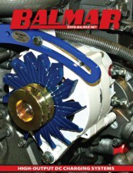
Typical <strong>MC</strong>-<strong>612</strong>-<strong>DUAL</strong><br />
System Installation<br />
Regulator is shown installed with<br />
<strong>Balmar</strong> 6-Series alternators. See<br />
your alternator installation manual<br />
for specific terminal connection information<br />
for your alternator. See<br />
detailed wiring instructions for<br />
specific connection points for optional<br />
wiring additions not shown.<br />
LIMITED PRODUCT WARRAnTY<br />
BALMAR warrants to the original consumer/purchaser the product is free from any defects in material or workmanship for a period<br />
of one year from the date of purchase. If any such defect is discovered within the warranty period, BALMAR will replace the regulator<br />
free of charge, subject to verification of the defect or malfunction upon delivery or shipping prepaid to BALMAR.<br />
This warranty DOES NOT apply to defects or physical damage resulting from abuse, neglect, accident, improper repair, alteration,<br />
modification, or unreasonable use of the products resulting in breakdown, cracked or broken cases nor are parts damaged by fire,<br />
water, freezing, collision, theft, explosion, rust, corrosion or items damaged in shipment in route to BALMAR for repair. BALMAR<br />
assumes no responsibility for consequential damage or loss or expense arising from these products or any labor required for service<br />
or repair.<br />
BALMAR WILL NOT repair or be held responsible for any product sent without proper identification <strong>and</strong> return address or RA<br />
number clearly marked on the package. You must include proof of date <strong>and</strong> place of purchase (photocopy of purchase invoice) or<br />
we cannot be responsible for repairs or replacement. In order to expedite warranty claims more efficiently, BALMAR asks that prior<br />
to returning a defective product for repair, you call their customer service department for a warranty return authorization number.<br />
If factory service is required, you can contact our BALMAR Customer Service Department Monday through Thursday, 7:30 AM<br />
to 5:30 PM, (PST)1-360 435-6100 ext “3”. Material required for the repair or replacement for the defective part or product is to be<br />
supplied free of charge upon delivery of the defective regulator to BALMAR, 18930 59 Ave. NE, Arlington, WA 98223. Customer<br />
is responsible for all return transportation charges <strong>and</strong> any air or rush delivery expense. BALMAR reserves the right to determine<br />
whether to repair or replace defective components.<br />
THE ABOVE LIMITATIONS MAY NOT APPLY TO YOU. SOME STATES DO NOT ALLOW LIMITATIONS ON HOW LONG AN IM-<br />
PLIED WARRANTY LASTS. NO PERSON, AGENT, DEALER IS AUTHORIZED TO GIVE ANY WARRANTY.<br />
BALMAR 19009 61st Ave. NE, Arlington, WA 98223 Phone: (360) 435-6100, Fax: (360) 435-3210 E-mail: balmar@balmar.net, Web: www.balmar.net<br />
- 16 -