Watts Premier RO Pure RO-4 Manual - Fresh Water Systems
Watts Premier RO Pure RO-4 Manual - Fresh Water Systems
Watts Premier RO Pure RO-4 Manual - Fresh Water Systems

Create successful ePaper yourself
Turn your PDF publications into a flip-book with our unique Google optimized e-Paper software.
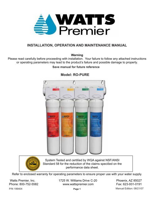
INSTALLATION, OPERATION AND MAINTENANCE MANUAL<br />
Warning<br />
Please read carefully before proceeding with installation. Your failure to follow any attached instructions<br />
or operating parameters may lead to the product’s failure and possible damage to property.<br />
Save manual for future reference<br />
Model: <strong>RO</strong>-PURE<br />
System Tested and certifi ed by WQA against NSF/ANSI<br />
Standard 58 for the reduction of the claims specifi ed on the<br />
performance data sheet.<br />
Refer to enclosed warranty for operating parameters to ensure proper use with your water supply.<br />
<strong>Watts</strong> <strong>Premier</strong>, Inc. 1725 W. Williams Drive C-20 Phoenix, AZ 85027<br />
Phone: 800-752-5582 www.wattspremier.com Fax: 623-931-0191<br />
P/N 199404<br />
<strong>Manual</strong> Edition: 08/21/07<br />
Page 1
Service Record<br />
Date of Purchase:__________ Date of Install:___________ Installed by:_____________<br />
Date<br />
NOTES:<br />
Sediment<br />
Filter<br />
(6 months)<br />
Model Number:__________ Serial Number:___________<br />
Carbon<br />
Pre-Filter<br />
(6 months)<br />
Page 2<br />
Membrane<br />
(2-5 years)<br />
Carbon<br />
Post-Filter<br />
(6 months)
WARRANTY REGISTRATION<br />
Thank you for selecting <strong>Watts</strong> <strong>Premier</strong> for your water fi ltration needs.<br />
4 Ways to Register<br />
1. On-line at www.wattspremier.com<br />
Register your product on-line and receive a 5% discount on your next on-line order, Plus receive reduced shipping.<br />
2. Call in your information 1-800-752-5582<br />
Call and we will enter your information.<br />
3. Fax in your information 623-931-0191<br />
Fax this form directly to us.<br />
4. Mail in the information.<br />
Please complete the form below. Mail to: <strong>Watts</strong> <strong>Premier</strong><br />
1725 W. Williams Dr. C-20<br />
Phoenix, AZ 85027<br />
<strong>Watts</strong> <strong>Premier</strong> Inc. is concerned for the safety of your personal information. <strong>Watts</strong> <strong>Premier</strong> collects personal information when you register with<br />
<strong>Watts</strong> <strong>Premier</strong>. This information is stored in our data base and we do not rent, sell, or share personal information with other people or nonaffi liated<br />
companies. We reserve the right to send you certain types of communications such as direct mail, email, or by telephone relating to our products<br />
or products that you have purchased. We limit access to your personal information to those employees who will directly provide you with services<br />
or products in order to do their jobs. We want to offer you four ways to communicate with us. 1.Online, 2.Fax, 3.Telephone, and 4. Mail the form<br />
below. By registering your product you will receive the full benefi t of our warranty. <strong>Watts</strong> <strong>Premier</strong> will also send you a semiannual fi lter change<br />
reminder beginning six months from date of installation. To insure the highest quality of your water, fi lters should be replaced every 6 months. If<br />
you have any questions or comments please give us a call at 1-800-752-5582 M-F 8:00am -5:00pm MST.<br />
Iowa Department of Public Health - Sales in Iowa require this to be completed,<br />
signed and returned. These signatures will be retained on fi le for two years.<br />
First Name:_________________________ Last Name:____________________________<br />
Address: ________________________________________ City: ____________________<br />
State: _______________________________________ Zip Code: ___________________<br />
Country: USA CANADA MEXICO OTHER ____________<br />
Phone # ______-__________ -__________ Email Address: ______________________<br />
Date of Purchase: ___________________ Date of Install: _______________________<br />
Installed By: SELF Plumbing Professional Where Purchased: ____________<br />
Model Number: _______________________ Serial Number: ____ - __________<br />
XXXXX - XXXXXX<br />
<strong>Watts</strong> <strong>Premier</strong>, Inc. 1725 W. Williams Drive C-20 Phoenix, AZ 85027<br />
Phone: 800-752-5582 www.wattspremier.com Fax: 623-931-0191<br />
Page 3<br />
Registering<br />
will insure you<br />
receive <strong>Watts</strong><br />
FREE<br />
Filter<br />
Reminder<br />
Service
Thank you for your purchase of a state of the art <strong>Watts</strong> <strong>Premier</strong> Reverse Osmosis (<strong>RO</strong>) water treatment system. <strong>Water</strong><br />
quality concerns are becoming more of a focus for the public. You may have heard about contaminants in the drinking water,<br />
such as Arsenic, Perchlorate, Chromium, Cryptosporidium or Giardia. There may also be some local water issues such as<br />
high levels of Lead and Copper. This <strong>Watts</strong> <strong>Premier</strong> water treatment system has been designed and tested to provide you<br />
with high quality drinking water for years to come. The following is a brief overview of the system.<br />
Your Reverse Osmosis System:<br />
Osmosis is the process of water passing through a semi permeable membrane in order to balance the concentration of<br />
contaminants on each side of the membrane. A semi permeable membrane is a barrier that will pass some particles like clean<br />
drinking water, but not other particles like arsenic and lead.<br />
Reverse osmosis uses a semi permeable membrane; however, by applying pressure across the membrane, it concentrates<br />
contaminants (like a strainer) on one side of the membrane, producing crystal clear water on the other. This is why <strong>RO</strong><br />
systems produce both clean drinking water and rinse water that is fl ushed from the system. This reverse osmosis system also<br />
utilizes carbon block fi ltration technology, and can therefore provide a higher quality drinking water than carbon fi ltration<br />
systems alone.<br />
Your system is a three or four stage <strong>RO</strong> which is based upon separate treatment segments within the one complete water<br />
fi ltration system. These stages are as follows:<br />
Stage 1 (Not in three stage units) – Sediment fi lter, recommended change 6 months.<br />
The fi rst stage of your <strong>RO</strong> system is a fi ve micron sediment fi lter that traps sediment and other particulate matter<br />
like dirt, silt and rust which affect the taste and appearance of your water.<br />
Stage 2 – Carbon fi lter, recommended change 6 months.<br />
The second stage contains a 5 micron carbon block fi lter. This helps ensure that chlorine and other materials that<br />
cause bad taste and odor are greatly reduced.<br />
Stage 3- Membrane, recommended change 2-5 years.<br />
Stage three is the heart of the reverse osmosis system, the <strong>RO</strong> membrane. This semi permeable membrane will<br />
effectively take out TDS, Sodium and a wide range of contaminants such as Percholate, Chromium, Arsenic, Copper,<br />
Lead as well as Cysts, such as Giardia and Cryptosporidium. Because the process of extracting this high quality<br />
drinking water takes time, your <strong>RO</strong> water treatment system is equipped with a storage tank.<br />
Stage 4- Carbon post fi lter, recommend change 6 - 12 months.<br />
The fi nal stage is a high quality carbon fi lter. Drinking water enters this fi lter after the water storage tank and it is<br />
used as a fi nal polishing fi lter.<br />
Note: Filter life may vary based upon local water conditions or use patterns.<br />
System Maintenance<br />
Just because you can not taste it, does not mean that it is not there. Contaminants such as Lead, Chromium and Arsenic are<br />
undetectable to the taste. Additionally, over time if you do not replace the fi lter elements, other bad tastes and odors will<br />
be apparent in your drinking water.<br />
This is why it is important to change out your fi lters at the recommended intervals as indicated in this system manual. When<br />
replacing the fi lter elements, pay special attention to any cleaning instructions. Should you have any further questions please<br />
refer to our website at www.wattspremier.com or call our customer service dept. at 1-800-752-5582.<br />
Page 4
Thank you for your purchase of a <strong>Watts</strong> <strong>Premier</strong> Reverse Osmosis system. With proper installation and<br />
maintenance, this system will provide you with high quality water for years to come. All of <strong>Premier</strong>’s water<br />
enhancement products are rigorously tested by independent laboratories for safety and reliability. If you<br />
have any questions or concerns, please contact our customer service department at 1-800-752-5582<br />
(outside USA 623-931-1977) or refer to our on-line troubleshooting at www.wattspremier.com.<br />
Table of Contents<br />
Service Record ...................................................................................................................................... 2<br />
Warranty Registration ............................................................................................................................ 3<br />
Operational Parameters ........................................................................................................................ 6<br />
Contents of Reverse Osmosis System .................................................................................................. 6<br />
Tools Recommended For Installation .................................................................................................... 6<br />
Drill a Hole for the Faucet in a Porcelain Sink ....................................................................................... 7<br />
Punch a Hole for the Faucet in a Stainless Steel Sink .......................................................................... 7<br />
<strong>Watts</strong> Chrome Monitor & Non-Monitored Faucet Installation ................................................................ 8<br />
Green Tube Connection (From <strong>RO</strong> Module To The Adapta Valve) ...................................................... 9<br />
Adapta Valve Installation ...................................................................................................................... 9<br />
Reverse Osmosis Module Mounting...................................................................................................... 9<br />
Drain Saddle Installation...................................................................................................................... 10<br />
Tank Ball Valve Installation .................................................................................................................. 10<br />
How To Use Quick Connect Fittings For Tubing Connections ..............................................................11<br />
Blue Tube Connection (From <strong>RO</strong> Module To The Tank) ...................................................................... 12<br />
Blue Tube Connection (From <strong>RO</strong> Module To The Faucet) .................................................................. 12<br />
Black 3/8” Tube Connection (From The Faucet To The Drain Saddle) ................................................ 12<br />
Red Tube Connection (From The Faucet To The Flow Restrictor) ...................................................... 13<br />
Start up Instructions............................................................................................................................. 13<br />
6 Month System Maintenance ............................................................................................................. 14<br />
Membrane Replacement .................................................................................................................... 14<br />
Check Air Pressure in the Tank ........................................................................................................... 15<br />
Parts List / Unit Drawing ..................................................................................................................... 15<br />
Trouble Shooting ................................................................................................................................ 16<br />
Performance Data Sheet ..................................................................................................................... 17<br />
Arsenic Fact Sheet .............................................................................................................................. 18<br />
Other Products from <strong>Watts</strong> <strong>Premier</strong> ............................................................................................... 19-21<br />
Limited Warranty ................................................................................................................................. 22<br />
Page 5
Operational Parameters<br />
Installation needs to comply with state and local plumbing regulations. This system is intended<br />
to be installed on the cold water line only.<br />
Operating Temperatures: Maximum 100°F (37.8°C) Minimum 40°F 4.4°C)<br />
Operating Pressure: Maximum 85 psi (7.43 g/cm2) Minimum 40 psi (2.80 kg/cm2)<br />
pH Parameters: Maximum 11 Minimum 2<br />
Iron: Maximum 0.2 ppm<br />
TDS (Total Dissolved Solids): < 1800 ppm<br />
Turbidity: < 5NTU<br />
Hardness: Recommended hardness not to exceed 10 grains per gallon, or 170ppm. System will<br />
operate with hardness over 10 grains but the membrane life may be shortened. Addition of a water<br />
softener may lengthen the membrane life.<br />
Note: The operating pressure in your home should be tested over a 24 hour period to attain the<br />
maximum pressure. If operating pressure is above 85 psi a pressure regulator is recommended. If it<br />
is above 100 psi then a pressure regulator is required (see part number 107001 on page 20).<br />
Note: Reverse Osmosis water should not be run through copper tubing as the purity of the water will<br />
leach copper causing an objectional taste in water and pin holes to form in tubing. <strong>Watts</strong> supplies<br />
speciality fi lters (part number 107008) that can be used if copper tubing follows the Reverse Osmosis<br />
unit. Be sure to follow any state or local regulations during installation.<br />
Contents of Reverse Osmosis (<strong>RO</strong>) System<br />
Note: A 4 Stage <strong>RO</strong> System has 4 quick change cartridges and a 3<br />
Stage <strong>RO</strong> System has 3 quick change cartridges.<br />
1 Tank<br />
1 <strong>RO</strong> Module (complete with fi lters)<br />
1 Parts Bag<br />
1 Faucet Bag<br />
1 <strong>Manual</strong> with Warranty Card<br />
If any of the items are missing please contact <strong>Premier</strong> prior to installing.<br />
Tools Recommended For Installation<br />
√ 1 1/4" Hole Saw Bit for Faucet opening<br />
√ Round Knock out Punch for Stainless Sinks 1 ¼”<br />
√ Adjustable Wrench<br />
√ Sharp Knife<br />
√ 1 / 2" Open End Wrench<br />
√ Phillips Screw Driver<br />
√ Needle Nose Pliers – Adjustable Pliers<br />
√ Electric Drill<br />
√ 1/8", 1/4" & 3/8" Drill Bits<br />
Page 6
Note:<br />
Step 1<br />
Step 2<br />
Step 3<br />
Step 4<br />
Most sinks are predrilled with 1 ½” or 1 ¼” diameter hole that you can use for your <strong>RO</strong><br />
faucet (If you are already using it for a sprayer or soap dispenser, you will need an<br />
additional hole for the faucet).<br />
Drill a Hole for the Faucet in a Porcelain Sink<br />
Porcelain sinks are extremely hard and can crack or chip easily. Use extreme caution when<br />
drilling. <strong>Premier</strong> accepts no responsibility for damage resulting from the installation of<br />
faucet.<br />
Determine desired location for the faucet on your sink and place a<br />
piece of masking tape on location where the hole is to be drilled. Mark<br />
the center of the hole on the tape.<br />
Using a variable speed drill on the slowest speed, drill a 1 / 8 ” Pilot<br />
hole through both porcelain and metal casing of sink at the center of<br />
the desired location. (If drill bit gets hot it may cause the porcelain to<br />
crack or chip).<br />
Using a 1 ¼” hole saw, proceed to drill the large hole. Keep drill speed<br />
on the slowest speed and use lubricating oil or liquid soap to keep the<br />
hole saw cool during cutting.<br />
Make sure the surroundings of the sink are cooled before mounting the<br />
faucet to the sink after drilling. Remove all sharp edges with a fi le.<br />
Punch a Hole for the Faucet in a Stainless Steel Sink<br />
Note:<br />
Step 5<br />
If mounting faucet to a Stainless Steel Sink you will need a 1 ¼”<br />
hole punch. The faucet opening should be centered between the<br />
back splash and the edge of the sink, ideally on the same side as<br />
the vertical drain pipe.<br />
Drill a ¼” pilot hole. Use the appropriate sized hole punch and an<br />
adjustable wrench to punch the hole in the sink.<br />
Once the hole is punched out, the faucet can be installed.<br />
Page 7
WATTS <strong>Premier</strong> Chrome Monitored & Non-Monitored<br />
(Top Mount) Faucet Installation<br />
Minimum Maximum<br />
Mounting Hole Size 1.00” 1.25”<br />
Torque on Toggle Bolt 5lb.in. (max)<br />
Step 6<br />
Step 7<br />
Step 8<br />
Step 9<br />
Gather and identify the faucet pieces.<br />
Remove faucet base & faucet spout from their respective<br />
plastic bags. From above the sink, feed the faucet base,<br />
tubing & toggle bolt down through the 1¼” mounting hole in<br />
the sink. Align the faucet base so that the handle is on the<br />
right side and the base is sitting fl ush on the sink top. Ensure<br />
that the soft rubber gasket is uniformly positioned in between<br />
the base and the top of the sink.<br />
Lift faucet base and remove the white paper from the gasket<br />
and stick it to the top of the sink in the appropriate position for<br />
the faucet base. Turn the handle down (towards you) to the<br />
“ON” position to reveal the tightening screw (located where<br />
the spout will be inserted). Using a phillips head screwdriver,<br />
turn the screw clockwise until the toggle bolt secures the<br />
faucet base snug onto the sink top, do not over torque toggle<br />
bolt (5lb.in. max)<br />
Once the faucet base is securely fastened to the sink top,<br />
insert the faucet spout into the faucet base until it is fully<br />
seated. Turn the handle up (vertical) to the “OFF” position.<br />
Completion of faucet installation (tubing connections) will be<br />
done later in this manual. Refer to the Black Tube Connection<br />
(page 12), Red Tube Connection (page 13), and Blue Tube<br />
Connection (page 12) sections of this manual.<br />
If your faucet is equipped with the monitoring function please proceed to the next step,<br />
otherwise please proceed to the next page.<br />
Faucet Battery Installation<br />
Step 10<br />
Insert the battery drawer with the battery into the base of the faucet until it is fl ush.<br />
NOTE: The + side of the battery faces up. The compartment drawer will not slide in if the battery is installed upside<br />
down.<br />
When the battery is fi rst installed, both the red and green lights will fl ash to indicate that both lights are functional. Thereafter,<br />
it will fl ash green only when the faucet handle is turned to the “ON” position. When your system is ready to be serviced<br />
(approximately six months) you will see the light fl ash red when the handle is turned to the “ON” position. Refer to the Six<br />
Month Maintenance (page 14) section of this manual for fi lter replacement.<br />
NOTE: If your water usage is high the red light may activate sooner than six months indicating the need for fi lter<br />
replacement.<br />
This faucet provides an electronic monitor that will tell you when it is time to replace the fi lters in your water<br />
treatment device. The light indicator will be green for the life of the fi lter, turning red once the life of the fi lter has<br />
been reached. This can occur after six months of use, or sooner for heavy water usage. To reset the electronic<br />
monitor during replacement of fi lters, simply slide out the battery from the faucet and reinsert. The battery life is<br />
expected to last one year, however, for heavy use the battery may need to be replaced sooner. For replacement,<br />
look for battery number CR2354 (<strong>Watts</strong> p/n:116082) which is available at your local battery store or contact <strong>Watts</strong><br />
<strong>Premier</strong> at 800-752-5582. You can also order online at www.wattspremier.com.<br />
Page 8
Green Tube Connection (From <strong>RO</strong> Module to The Adapta Valve)<br />
Step 11<br />
Step 12<br />
Remove a brass nut, plastic sleeve and brass insert from the<br />
parts bag. Place nut on the green tube (coming from the <strong>RO</strong><br />
Module) fi rst, then the plastic sleeve (small taper end of plastic<br />
sleeve must point to the end of tube) and then insert the brass<br />
insert into the end of the tube.<br />
Insert the green tube into the ¼” opening on the Adapta Valve<br />
(supplied in the parts bag) until it stops. Slide nut and sleeve<br />
down and thread onto the male pipe threads. Use a ½” wrench<br />
to securely tighten.<br />
Adapta Valve - Part# 134007<br />
Adapta Valve Installation - Part# 134007<br />
Confi guration for 3/8” compression fi ttings Hot Supply Cold Supply Confi guration for 1/2” compression fi ttings<br />
Step 13 The green tubing may be removed from the quick connect fi tting on the <strong>RO</strong> Module to ease<br />
with the installation of the Adapta Valve to the supply line (see page 11 for quick connect<br />
fi tting use directions). Make sure to re-attach the green tube to the <strong>RO</strong> Module after the<br />
Adapta Valve has been installed.<br />
Step 14 Turn off the cold water supply to the faucet by turning the angle stop valve<br />
completely off.<br />
Step 15 Attach adapta valve as illustrated in the photos above, choosing the confi guration that fi ts<br />
your plumbing. (When attaching the adapta valve to straight pipe threads, use tefl on tape on<br />
the treads.)<br />
Caution: <strong>Water</strong> supply line to the system must be from the cold water supply line only. Hot water<br />
will severely damage your system.<br />
Note: If the green tubing was removed from the quick connect fi tting on the <strong>RO</strong> Module in Step<br />
13, re-attach it to the <strong>RO</strong> Module now (see page 11 for quick connect fi tting use directions).<br />
Reverse Osmosis Module Mounting<br />
Step 16 Determine best location for the <strong>RO</strong> module to be mounted to allow<br />
for future system maintenance. The parts bag has 2 self tapping<br />
screws. Using a phillips screwdriver, screw them into the cabinet<br />
wall using the mounting bracket as a guide.<br />
Note: Do not cut any <strong>RO</strong> system tubes at this time<br />
Page 9
Drain Saddle Installation - Part# 164016<br />
Drain Saddle fi ts standard 1 ¼” – 1 ½” drain pipes<br />
Caution: If you have a garbage disposal, do not install the drain line near it.<br />
Installation of the drain line must be either above the disposal, or if<br />
a second sink drain is available, install it above the cross bar on the<br />
second sink. Installation of the drain line near a garbage disposal<br />
may cause the drain line to plug. If no other installation of drain line<br />
is available, <strong>Watts</strong> offers drain line installation kits that can be used<br />
with garbage disposals (part numbers 164014 and 164020).<br />
Step 17<br />
Step 18<br />
Step 19<br />
Step 20<br />
Step 21<br />
Gather the pieces of the drain saddle<br />
1 Black compression nut 1 Semicircle bracket with opening<br />
2 Screws 1 Foam washer<br />
2 Nuts for screws 1 Semicircle bracket<br />
The small square black foam gasket with a circle cut out of the<br />
middle must be applied to the inside of the drain saddle. Remove<br />
sticky tape backing and stick to the drain saddle as shown.<br />
Assemble the drain saddle around the drain pipe at least 1 ½”<br />
above the nut of the P-trap to allow for the removal of the P-trap if<br />
necessary. Using a Philips screw driver tighten screws evenly and<br />
securely on both sides of the drain saddle.<br />
Insert a ¼” drill bit into the opening of the drain saddle and drill a<br />
hole in to the drain pipe. NOTE: Take extreme caution to only<br />
drill through one side of the drain pipe and not all the way<br />
through.<br />
Attach black compression nut to the drain saddle, but do not tighten<br />
at this time. The black tubing will be installed later.<br />
Caution: Do not over-tighten the screws. Over-tightening screws may crack<br />
the drain saddle.<br />
Tank Ball Valve Installation - Part#: 134018<br />
Tefl on tape must be applied in a clockwise direction. Wrap (7 to<br />
12 turns) around the male pipe threads (MPT) on the stainless<br />
steel fi tting on top of the tank.<br />
Thread the quick connect ball valve (supplied in the parts bag) onto<br />
the stainless steel connector on the tank.<br />
Note: Do not over-tighten plastic connections.<br />
Page 10
How To Use the Quick Connect Fittings For Tubing Connections<br />
To make a connection, the tube is simply pushed into the fi tting. Place a piece of tape 1/2” from end<br />
of tube to indicate how far the tube should be inserted. The unique patented locking system holds the<br />
tube fi rmly in place without deforming it or restricting fl ow.<br />
NOTE: These diagrams are just to show how the quick connect fi ttings work, your product may not<br />
have this exact connector part.<br />
It is essential that the outside diameter be free of score<br />
marks and that burrs and sharp edges be removed before<br />
inserting into fi tting.<br />
Push the tube into the fi tting, to the tube stop. The collet<br />
(gripper) has stainless steel teeth which hold the tube<br />
fi rmly in position while the O-ring provides a permanent<br />
leak proof seal.<br />
Page 11<br />
Fitting grips before it seals. Ensure tube is pushed into<br />
the tube stop.<br />
Pull on the tube to check that it is secure. It is a good practice<br />
to test the system prior to leaving site and /or before use.<br />
To disconnect, ensure the system is depressurized before<br />
removing the tube. Push in collect squarely against face<br />
of fi tting. With the collet held in this position, the tube can<br />
be removed. The fi tting can then be reused.
Blue Tube Connection (From The <strong>RO</strong> Module To TANK)<br />
Step 22<br />
Position tank in desired location. Stand it upright or lay it on<br />
its side (using the black plastic stand). Measure the blue tube<br />
(marked “TANK”) from the <strong>RO</strong> module over to the tank and cut<br />
it to length leaving a straight edge on the end of the tube. Then<br />
insert the tube into the quick connect fi tting on the tank ball<br />
valve. Make sure the tube is pushed in all the way to the tube<br />
stop (see page 11 for quick connect fi tting use directions).<br />
Blue Tube Connection (From The <strong>RO</strong> Module To FAUCET)<br />
Step 23 Determine where the 3/8” blue tubing from the faucet and the 1/4”<br />
blue tubing (marked “FAUCET”) from the <strong>RO</strong> Module would join<br />
together comfortably. Cut the tubes leaving a straight cut on both<br />
tubes. Insert the 1/4” blue tube (marked “FAUCET”) from the <strong>RO</strong><br />
module into the 1/4” end of the 1/4” x 3/8” quick connect union<br />
supplied in the parts bag. Make sure the tube is pushed in all<br />
the way to the tube stop.<br />
Step 24 Insert the 3/8” blue tube from the faucet into the remaining 3/8”<br />
open end of the 1/4” x 3/8” quick connect union. Make sure the<br />
tube is pushed in all the way to the tube stop.<br />
Black 3/8” Tube Connection (From FAUCET To The DRAIN SADDLE)<br />
Note:<br />
Step 25<br />
Step 26<br />
Note:<br />
The tubing must be as SHORT and STRAIGHT as possible, making a downward slope<br />
from faucet to drain saddle to allow for proper drainage.<br />
Measure the 3/8” black tube from faucet to the black drain<br />
saddle so that it is as short and straight as possible, then<br />
make a straight cut through tube.<br />
Remove black plastic nut from drain saddle. Slip black tube<br />
through black nut. Insert black tube into the opening in the<br />
drain saddle and tighten the black nut securely.<br />
This is a gravity fed line, if there is any dip or kink in the tube<br />
the rinse water will not fl ow into the drain properly. <strong>Water</strong><br />
will back up and come out the air gap hole in the back of the<br />
faucet base.<br />
Page 12
Red Tube Connection (From FAUCET To The FLOW RESTRICTOR)<br />
Step 27<br />
Determine where the 1/4” red tubing from the faucet and<br />
the open end of the fl ow restrictor (attached to the end<br />
of the 1/4” black tubing from the <strong>RO</strong> Module) would join<br />
together comfortably. Cut the tubes to length, making<br />
sure the cut ends are straight. Unscrew the supplied<br />
compression nut from the open end of the fl ow restrictor<br />
and push the nut onto the end of the red tube. Insert the<br />
red tube (with attached nut) into the open end of the fl ow<br />
restrictor making sure the tube is pushed in all the way to<br />
the tube stop. Once the red tube is fully inserted, securely<br />
tighten the compression nut onto the fl ow restrictor.<br />
Start up Instructions<br />
Step 1<br />
Step 2<br />
Step 3<br />
Step 4<br />
Step 5<br />
Turn on the incoming cold water. Open the Adapta-Valve installed earlier in this manual<br />
(page 9). Check the system for leaks and tighten any fi tting as necessary. (Check over the<br />
next 24 hours to ensure no leaks are present).<br />
Open the <strong>RO</strong> faucet and leave it open until water begins to trickle out. (it will come out<br />
slowly and may sputter at fi rst. The water may look dark, which is carbon from the fi nal<br />
fi lter. This is normal and will go away). Once the water begins to trickle out, close the <strong>RO</strong><br />
faucet.<br />
The tank will take between 4 to 6 hours to fi ll completely (depending on the size of the<br />
membrane, local water temperature and pressure). After the tank has fi lled, open the <strong>RO</strong><br />
Faucet to fl ush the tank completely to remove carbon particles from fi nal fi lter. Repeat this<br />
step two more times. The fourth tank can be used for drinking. Note: The fl ushing of the<br />
tank 3 times is only necessary during initial installation. This should take about a day to<br />
complete.<br />
An optional ice maker kit (not included) may be purchased from <strong>Watts</strong> <strong>Premier</strong> by calling<br />
1-800-752-5582 or buy on-line at www.wattspremier.com. If system is connected to an ice<br />
maker, turn the ice maker off (or do not allow water to fl ow to the ice maker) until Step 3<br />
fl ushing is complete and the tank has been allowed to completely fi ll. Connection from the<br />
<strong>RO</strong> to the ice maker system should have an in-line valve installed before the ice maker so it<br />
can easily be closed to prevent water fl owing to the ice maker during start up and periodic<br />
maintenance. Your <strong>RO</strong> tank must be allowed to fi ll up in order for the ice maker system to<br />
work properly. (If you are installing an ice maker kit from <strong>Watts</strong>, tee off after the fi nal fi lter).<br />
Complete the warranty registration (page 3) and submit to <strong>Watts</strong> <strong>Premier</strong>. <strong>Premier</strong> uses<br />
this information to provide the latest information about water quality concerns as well as<br />
a free fi lter change reminder service. Inspect the reverse osmosis system periodically to<br />
ensure the unit is functioning properly.<br />
Page 13
This reverse osmosis system contains a replaceable component (the <strong>RO</strong> membrane) which is critical to the effi ciency of<br />
the system. Replacement of this reverse osmosis membrane should be with one of identical specifi cations as defi ned by<br />
<strong>Watts</strong> <strong>Premier</strong> to assure the same effi ciency and contaminant reduction performance.<br />
6 Month System Maintenance<br />
<strong>Watts</strong> <strong>Premier</strong> sells a fi lter change kit which includes all replacement fi lters<br />
needed. Call 1-800-752-5582 or buy on-line at www.wattspremier.com.<br />
Items needed:<br />
√ One sediment fi lter (RED Label - 4 Stage Only P/N: 105311)<br />
√ One carbon pre-fi lter (YELLOW Label P/N: 105351)<br />
√ One carbon post-fi lter (BLUE Label P/N: 105341)<br />
√ Towel to catch water from fi lter housings.<br />
NOTE:<br />
Step 1<br />
Step 2<br />
Step 3<br />
Step 4<br />
Your <strong>RO</strong> module is equipped with valved heads which will automatically<br />
turn off the water supply to each fi lter when the fi lter is released, thus<br />
you do not need to turn off the incoming water supply at the Adapta-<br />
Valve. The faucet must be off when fi lters are replaced.<br />
Place the towel under the <strong>RO</strong> module to catch any excess water that<br />
drips out from the fi lters during the changeover.<br />
To make the removal of the fi lter housings easier, the heads & housings<br />
may be lifted up to 90 degrees as shown in the pictures to the right.<br />
Starting with the sediment fi lter (RED Label) push & hold the button on<br />
the valved head and pull downward (from the head) to remove the fi lter<br />
housing. Release button and discard old fi lter housing.<br />
Make sure to remove the cap off of the new replacement fi lter. Insert the<br />
new fi lter housing into the valved head until you hear an audible “click”<br />
(the button does not need to be pressed to install new fi lters).<br />
Repeat this procedure for the 2nd and 4th housings. When fi nished<br />
fl ush your tank completely once to remove any natural carbon fi nes from<br />
the <strong>RO</strong> system. Check over the next 24 hours to ensure no leaks are<br />
present.<br />
Membrane Replacement (GREEN Label P/N: 105331)<br />
Membranes have a life expectancy of between 2 and 5 years, depending on the incoming water<br />
conditions and the amount of use of the <strong>RO</strong> system.<br />
Normally, a membrane would be replaced during a semiannual or annual fi lter change. However, if<br />
at any time you notice a reduction in water production or an unpleasant taste in the reverse osmosis<br />
water, it could be time to replace the membrane. A water sample may be sent into <strong>Premier</strong> for a<br />
free test or a TDS (total dissolved solids) monitor can be purchased from <strong>Watts</strong> <strong>Premier</strong> to test the<br />
incoming and reverse osmosis water. Membranes should be replaced when TDS reduction is 80% or<br />
less. TDS Monitors are available for purchase on page 20 of this manual.<br />
To send a water sample, include ½ cup of tap water and ½ cup of the system’s reverse osmosis water<br />
in clean containers. Clearly mark each container. <strong>Watts</strong> <strong>Premier</strong> will test the water and call or mail<br />
you the results.<br />
Step 1 To change your membrane follow the instructions for the 6 Month System Maintenance<br />
(previous section). The procedure to remove and change the membrane housing is the<br />
same as all the other fi lter housings on the <strong>RO</strong> module.<br />
Step 2<br />
Check over the next 24 hours to ensure no leaks are present.<br />
Page 14
Check Air Pressure in the Tank<br />
Note:<br />
Step 1<br />
Step 2<br />
Parts List<br />
Check air pressure only when tank is empty of water!<br />
Check air pressure in the tank when you notice a decrease in<br />
available water from the <strong>RO</strong> system.<br />
It is recommended that you drain the tank of water, and then<br />
pump up the <strong>RO</strong> tank in order to ensure all water is out of the<br />
tank. Air can be added with a bicycle pump using the schrader<br />
valve that is located on the bottom side of the tank.<br />
Once all water in the tank is purged out, check air pressure of the<br />
tank. If you added too much air to the tank and it is higher than<br />
5 - 7 psi, allow air out until you have 5 - 7 psi in the tank.<br />
3/8"<br />
BLUE<br />
TUBE<br />
3/8" BLACK TUBE<br />
3/8" x 1/4" UNION<br />
1/4" RED TUBE<br />
TANK BALL<br />
VALVE<br />
DRAIN SADDLE<br />
1/4" BLUE TUBE<br />
1/4" BLUE TUBE<br />
ADAPTA<br />
VALVE<br />
FLOW RESTRICTOR<br />
* The reverse osmosis system contains a replaceable treatment component, critical for the effective reduction of total<br />
dissolved solids and that the product water shall be tested periodically to verify that the system is performing properly<br />
Item # Part # Description<br />
1 531150 <strong>RO</strong>4-PNP-11-50 (Head & 4 Filter Cartridges)<br />
2 125089 FITTING-ELBOW-90-QC-1/4TX1/4I<br />
3 622036 FLOW RESTRICT-550-STAND ALONE<br />
4 134003 VALVE-SHUT OFF 1/4” Q.C. (RES)<br />
5 119007 TANK-3 GALLON-METAL-WHITE<br />
7 134007 ADAPTA VALVE<br />
8 116074 FAUCET-AG-WATTS-CH<strong>RO</strong>ME-MONITOR<br />
9 134018 VALVE-BALL-ELB-1/4QCX1/4F<br />
SHUT OFF VALVE<br />
1/4"<br />
GREEN<br />
TUBE<br />
Item # Part # Description<br />
10 125037 FITTING-UNION-1/4”T X 3/8”T-DM<br />
11 164016 DRAIN SADDLE 3/8”<br />
12 119028 TANK STAND<br />
13 610109 GREEN TUBING<br />
14 610113 BLACK TUBING<br />
15 610117 BLUE TUBING<br />
Page 15<br />
1/4" BLACK TUBE
T<strong>RO</strong>UBLE SHOOTING<br />
Problem Cause Solution<br />
1. Low/Slow Production Low <strong>Water</strong> Pressure Assure a minimum of 40 psi incoming water pressure.<br />
<strong>Premier</strong> sells a booster pump if home water pressure is<br />
low. Maker sure water supply is turned on and Adapta<br />
Valve is all the way open<br />
Crimps in tubing Check tubing and straighten or replace as necessary.<br />
Clogged pre-fi lters Replace pre-fi lters.<br />
Fouled membrane Replace membrane and fl ow restrictor.<br />
2. Milky colored <strong>Water</strong> Air in system Air in the system is a normal occurrence with initial<br />
start up of the <strong>RO</strong> system. This milky look will<br />
disappear during normal use within 1-2 weeks. If<br />
condition reoccurs after fi lter change, drain tank 1 to 2<br />
times.<br />
3. <strong>Water</strong> constantly Low water pressure See #1 Above<br />
running unit will not<br />
shut off Crimp in supply tube Check tubing and straighten or repair as necessary<br />
4. Noise / <strong>Water</strong> from Crimp or restriction in Check tubing and straighten or repair as necessary.<br />
faucet vent hole or noise drain line Straighten all drain lines. Clear blockage. Cut off any<br />
from drain Excess tubing<br />
Drain tube clogged Caused from dishwasher or garbage disposal.<br />
Disconnect the 3/8” black line at the drain, clean the<br />
3/8” black line out with a wire, then reconnect. Blowing<br />
air through the line will not always remove the clog.<br />
5. Small amount of water in System starting up Normally it takes 6-10 hours to fi ll tank. Note: low<br />
storage tank incoming water pressure and/or temperature can<br />
drastically reduce production rate.<br />
Low water pressure See #1 above.<br />
To much air in tank Tank air pressure should be 5 psi when empty of water.<br />
If below 5 psi add air or bleed if above 5 psi.<br />
Check only when tank is empty of water.<br />
See previous page.<br />
6. <strong>Water</strong> leaks from the fi lter / Not properly inserted Re-insert the fi lter / membrane housing.<br />
membrane housing<br />
7. Low water fl ow from faucet Check air in tank Use a Digital Air Gauge for best results. The empty<br />
tank pressure should be 5-7 psi. To reset the air pressure<br />
in the tank turn off water supply and drain tank by<br />
opening faucet. When water stops fl owing out of the<br />
faucet. Remove schrader valve cover pump air into<br />
tank until water stops fl owing from the faucet. Release<br />
the air out of the schrader valve until you reach 5-7 psi.<br />
Replace schrader valve cover. Turn on <strong>Water</strong>.<br />
Page 16
<strong>Watts</strong> <strong>Premier</strong> Inc.<br />
1725 W. Williams Drive C-20<br />
Phoenix, AZ 85027 USA<br />
California Certifi cation # 07-1882<br />
<strong>RO</strong>-<strong>Pure</strong><br />
System conforms to NSF Standard 58 for specifi c claims.<br />
GENERAL USE CONDITIONS:<br />
1. System to be used with municipal or well water sources treated and tested on regular basis to insure bacteriological safe quality. DO NOT use with water that<br />
is microbiologically unsafe or unknown quality without adequate disinfection before and after the system. <strong>Systems</strong> certifi ed for cyst reduction may be used on<br />
disinfected water that may contain fi lterable cysts.<br />
2. This system is acceptable for treatment of infl uent concentrations of no more than 27 mg/L nitrate and 3 mg/L nitrite in combination measured as N and is<br />
certifi ed for nitrite/nitrate reduction only for water supplies with a pressure of 280 kPa (40 psig) or greater. If your water supply is under 40 psi <strong>Watts</strong> <strong>Premier</strong><br />
recomends the use of a <strong>RO</strong> booster pump for proper operation.<br />
3. Operating Temperature: Maximum: 100°F (40.5°C) Minimum: 40° (4.4°)<br />
4. Operating <strong>Water</strong> Pressure: Maximum: 85 psi (6.0kg/cm2) Minimum: 40 psi (2.8kg/cm2)<br />
5. pH 2 to 11<br />
6. No iron present in incoming feed water supply.<br />
7. Hardness of more than 10 grains per gallon (170 ppm) may reduce <strong>RO</strong> membrane life expectancy.<br />
8. Recommend TDS (Total Dissolved Solids) not to exceed 1800 ppm.<br />
RECOMMENDED REPLACEMENT PARTS AND CHANGE INTERVALS:<br />
Note: Depending on incoming feed water conditions replacement time frame may vary.<br />
Description Change time Frame Cost<br />
Sediment Pre-fi lter: #105311 6 Months $12.50<br />
Carbon Pre-fi lter: #105351 6 Months $19.30<br />
Final Carbon fi lter #105361 12 Months $19.30<br />
R.O. Membrane: #105331 2 to 5 years $72.95<br />
This system has been tested according to NSF/ANSI 58 for reduction of the substances listed below. The concentration of the indicated substances in water<br />
entering the system was reduced to a concentration less than or equal to the permissible limit for water leaving the system as specifi ed in NSF/ANSI 58. This<br />
system has been tested for the treatment of water containing pentavalent arsenic (also known as As (V), As (+5), or arsenate) at concentrations of 0.30 mg/L or<br />
less. This system reduces pentavalent arsenic, but may not remove other forms of arsenic. This system is to be used on water supplies containing a detectable free<br />
chlorine residual at the system inlet or on water supplies that have been demonstrated to contain only pentavalent arsenic. Treatment with chloramine (combined<br />
chlorine) is not suffi cient to ensure complete conversion of trivalent arsenic to pentavalent arsenic, Please see the Arsenic Facts section of the Performance Data<br />
Sheet for further information.<br />
Avg. In. Avg. Eff. % Reduction pH Pressure Max Eff. Inf. challenge Max Allowable<br />
(mg/L) (mg/L) mg/L concentration concentration<br />
mg/L mg/L<br />
Arsenic (Pentavalent) .310 0.001 99.6% 7.24 50psi 0.002 0.30±10% 0.010 mg/L<br />
Barium Reduction 9.2 0.08 99.0% 7.64 50psi 0.12 10.0±10% 2.0<br />
Cadmium Reduction 0.031 0.0004 98.0% 7.49 50psi 0.0008 0.03±10% 0005<br />
Chromium (Hexavalent) 0.30 0.002 99.0% 7.24 50psi 0.004 0.03±10% 0.1<br />
Chromium (Trivalent) 0.30 0.001 99.0% 7.64 50psi 0.002 0.03±10% 0.1<br />
Copper Reduction 3.2 0.02 99.0% 7.40 50psi 0.04 3.0±10% 1.3<br />
Cysts 92,000#/ml 3 #/ml 99.99% 7.44 50psi 18 minimum 50,000/mL N/A<br />
Fluoride Reduction 8.7 0.19 97.0% 7.24 50psi 0.3 8.0±10% 1.5<br />
Lead Reduction 0.15 0.002 98.8% 7.39 50psi 0.005 0.15±10% 0.0107<br />
Nitrate 27 3.8 86.0% 7.24 50psi 4.3 27.0 ±10% 10.0<br />
Nitrite 3.1 0.41 86.0% 7.24 50psi 0.46 3.0 ±10% 1.0<br />
Nitrate + Nitrite 30 4.2 86.0% 7.24 50psi 4.8 30.0 ±10% 10.0<br />
Perchlorate 0.14 0.003 97.0% 7.39 50psi 0.005 mg/L 0.10±10% 0.006<br />
Radium 226/228 25pCi/L 5pCi/L 80.0% 7.24 50psi 5pCi/L 25pCiL±10% 5pCiL<br />
Selenium 94.85
Arsenic Fact Sheet<br />
Arsenic (As) is a naturally occurring contaminant found in many ground waters. Arsenic in water<br />
has no color, taste or odor. It must be measured by an arsenic test kit or lab test.<br />
Public water utilities must have their water tested for arsenic. You can obtain the results from your<br />
water utility contained with in your consumer confi dence report. If you have your own well, you<br />
will need to have the water evaluated. The local health department or the state environmental<br />
health agency can provide a list of test kits or certifi ed labs.<br />
There are two forms of arsenic: pentavalent arsenic (also called As (V), As (+5)) and trivalent<br />
arsenic (also called As (III), As (+3)). In well water, arsenic may be pentavalent, trivalent, or a<br />
combination of both. Although both forms of arsenic are potentially hazardous to your health,<br />
trivalent arsenic is considered more harmful than pentavalent arsenic.<br />
<strong>RO</strong> systems are very effective at removing pentavalent arsenic. A free chlorine residual will<br />
rapidly convert trivalent arsenic to pentavalent arsenic. Other water treatment chemicals such<br />
as ozone and potassium permanganate will also change trivalent arsenic to pentavalent arsenic.<br />
A combined chlorine residual (also called chloramine) where it does convert trivalent arsenic to<br />
pentavalent arsenic, may not convert all the trivalent arsenic in to pentavalent arsenic. If you get<br />
your water from a public water utility, contact the utility to fi nd out if free chlorine or combined<br />
chlorine is used in the water system.<br />
This <strong>Watts</strong> <strong>Premier</strong> reverse osmosis system is designed to remove up to 98% of pentavalent<br />
arsenic. It will not convert trivalent arsenic to pentavalent arsenic. Under laboratory standard<br />
testing conditions, this system reduced 0.30 mg/L (ppm) pentavalent arsenic to under 0.010<br />
mg/L (ppm) (the USEPA standard for drinking water). Actual performance of the system may<br />
vary depending on specifi c water quality conditions at the consumer’s installation. In addition to<br />
the independent laboratory standard testing conditions <strong>Watts</strong> <strong>Premier</strong> has conducted additional<br />
fi eld testing on our reverse osmosis units to determine trivalent arsenic reduction capabilities.<br />
Based upon <strong>Watts</strong> <strong>Premier</strong> fi eld testing, it has been determined that the <strong>RO</strong> units are capable<br />
of reducing up to 67% of trivalent arsenic from the drinking water.<br />
The <strong>RO</strong> membrane component of this <strong>Watts</strong> <strong>Premier</strong> reverse osmosis system must be maintained<br />
according to its recommended maintenance cycle. Specifi c component identifi cation and ordering<br />
information can be found in the installation/operation manual maintenance section, by phone at<br />
1-800-752-5581 or online www.wattspremier.com<br />
California Proposition 65 Warning<br />
WARNING: this product contains chemicals known to the State of California to cause cancer<br />
and birth defects or other reproductive harm. (Installer: California law requires that this warning<br />
be given to the consumer). For more information: www.watts.com/prop65.<br />
Page 18
Other Products from <strong>Watts</strong> <strong>Premier</strong><br />
<strong>Watts</strong> <strong>Premier</strong> has other fi ne water fi ltration products and accessories to enhance your water and to<br />
compliment your existing <strong>RO</strong> System. Listed on the next several pages are only a few of the items we<br />
offer. Visit our website at www.wattspremier.com or call our Customer Service Representatives at<br />
1-800-752-5582 (inside USA) 1-623-931-1977 (outside USA) for more products.<br />
<strong>Watts</strong> <strong>Premier</strong> sells a fi lter change kit which includes all replacement fi lters needed.<br />
Call 1-800-752-5582 or buy on-line at www.wattspremier.com.<br />
Top Mount Faucets by <strong>Watts</strong> <strong>Premier</strong><br />
These attractively designed faucets feature a long reach spout to compliment<br />
all styles of kitchen decor. The unique top mount design allows for easy<br />
above counter installation. The Monitored version of this faucet has an LED<br />
light that turns red to notify you for fi lter replacement.<br />
Part No. 116000 - Chrome (Non-Monitored) *$49.95 each<br />
116072 - Brushed Nickel (Non-Monitored) *$59.95 each<br />
116074 - Chrome (Monitored) *$69.95 each<br />
<strong>Watts</strong> <strong>Premier</strong> Hot <strong>Water</strong> Recirculation Pump<br />
Bring convenience and saving to your home, giving you hot water instantly at<br />
every faucet, when you need it. This unique product is easy to install and not<br />
only provides you with the convenience of hot water when you need it, but<br />
saves an average of over 11,000 gallons per year.<br />
Part No. 500800 *$229.99 each<br />
3/8” Ice Maker Kit for <strong>RO</strong> and Filtration<br />
3/8 inch connection includes 30 feet tubing, ball valve, and fi ttings.<br />
Part No. 500102 *$ 17.00 each<br />
Page 19
<strong>Watts</strong> <strong>Premier</strong> Ice Maker Kit - High effi ciency replaceable fi lter that can last up<br />
to 5 years or 20,000 gallons. Prefect for residential and commercial ice makers<br />
as well as refrigerators, drinking fountains, coffee & tea brewers, motor homes<br />
and campers. Reduces chlorine taste and odor.<br />
Part No. 500327 *$36.95 each<br />
Whole House Filter<br />
Great for sediment problems such as in well water supply or areas where dirt<br />
and rust particles are a problem. Includes three 50 Micron sediment fi lters, and<br />
wrench. (3/4” ports).<br />
Part No. 500223 *$86.95 each<br />
Replacement fi lter *$ 7.95 each<br />
Part No. 304007<br />
<strong>Water</strong> Pressure Gauge<br />
This gauge mounts onto your outside hose connection to accurately show your<br />
home’s water pressure up to 300 psi. A red needle shows peak overnight pressure,<br />
which may exceed readings during the day. High pressure readings may<br />
indicate the need for pressure regulator to prevent damage to appliances.<br />
Part No. 261003 *$14.95 each<br />
Pocket Total Dissolved Solids (TDS) Monitor<br />
Test water electronically to verify reverse osmosis membrane effectiveness.<br />
Carrying case included.<br />
Part No. 273001 *$39.95/ea<br />
Whole House High Performance <strong>Water</strong> Pressure Regulator<br />
Provides water pressure control solutions for residential, commercial, and industrial<br />
applications. Offers durability and years of continuous trouble free operation.<br />
Part No. 107001 *$69.95 each<br />
* All prices subject to change.<br />
Page 20
Removing chlorine from your shower<br />
Special Chlorgon & KDF media – More effective then carbon medias with<br />
hot water applications in the removal of the following.<br />
√ Free Chlorine (CL-)<br />
√ Combined Chlorine (Sodium Hypochlorite)<br />
√ Hydrogen Sulfi de (Rotten egg smell)<br />
√ Plus, its pH balanced.<br />
Deluxe Shower Handle with Built in Filter Replacement fi lters<br />
2PK<br />
5-Way Massaging Spray<br />
72” Reinforced Hose<br />
High Strength Bracket<br />
Triple Plated Finish<br />
Reversible Filter Cartridge (Model HHC)<br />
Cartridge Life Rating: 3 months<br />
Part No. 107090 WHITE *$42 .95<br />
Part No. 107091 CH<strong>RO</strong>ME *$44.95 Part No. 107075 *$14.95/pk<br />
Shower Falls Deluxe Shower Handle with Built in Filter<br />
Curved Ergonomic Shower Handle<br />
Filter Handle Extension Replacement fi lters 2PK<br />
Dual Swivel Adjustment<br />
Ultra Deluxe 5 Way Massaging Spray<br />
72” Reinforced Hose<br />
Chrome Plated Brass Bracket & Swivel Ball Extension<br />
Triple Plated Finish<br />
Reversible Filter Cartridge (Model HHC)<br />
Cartridge Life Rating: 3 months<br />
Part No. 107095 CH<strong>RO</strong>ME *$55.95 Part No. 107075 *$14.95/pk<br />
All-In-One reversible High-Flow Filter<br />
Deluxe 5-Way Massaging Spray Replacement fi lter<br />
Soft-Touch Adjustment Pads<br />
Anti-Scaling Spray Nozzle<br />
High Strength Housing<br />
Triple Plated Finish<br />
Cartridge Life Rating: 6 months<br />
Part No. 107098 White/Chrome *$47.50 Part No. 107080 *$18.95/ea<br />
Part No. 107099 White/Gold *$45.00<br />
*All prices subject to change.<br />
Page 21<br />
√ Iron oxide (rust water)<br />
√ Dirt, sediment<br />
√ Odors
Limited Warranty<br />
What your Warranty Covers:<br />
If any part of your WATTS PREMIER Reverse Osmosis System is defective in workmanship (excluding replaceable<br />
fi lters and membranes), return unit after obtaining a return authorization (see below), less tank, within 3 years of original<br />
retail purchase, WATTS PREMIER will repair or, at WATTS PREMIER’S option, replace the system at no charge.<br />
How to obtain Warranty Service:<br />
For warranty service, call 1-800-752-5582 for documentation and a return authorization number. Once the return<br />
authorization number has been created, ship your Reverse Osmosis unit (less tank) to our factory, freight and insurance<br />
prepaid, with proof of date of original purchase. Include a note stating the problem experienced and include your name,<br />
address and your return authorization number. No returns will be accepted with out the proper return authorization<br />
number. <strong>Premier</strong> will repair it, or replace it, and ship it back to you prepaid.<br />
What this warranty does not cover:<br />
This warranty does not cover defects resulting from improper installation, (contrary to WATTS PREMIER’s printed<br />
instructions), from abuse, misuse, misapplication, improper maintenance, neglect, alteration, accidents, casualties, fi re,<br />
fl ood, freezing, environmental factors, water pressure spikes or other such acts of God.<br />
This warranty will be void if defects occur due to failure to observe the following conditions:<br />
1. The Reverse Osmosis System must be hooked up to a potable municipal or well cold water supply.<br />
2. The hardness of the water should not exceed 10 grains per gallon, or 170 ppm.<br />
3. Maximum incoming iron must be less than 0.2 ppm.<br />
4. The pH of the water must not be lower than 2 or higher than 11.<br />
5. The incoming water pressure must be between 40 and 85 pounds per square inch.<br />
6. Incoming water to the <strong>RO</strong> cannot exceed 105 degrees F (40 degrees C.)<br />
7. Incoming TDS/Total Dissolved Solids not to exceed 1800 ppm.<br />
8. Do not use with water that is microbiologically unsafe or of unknown quality without<br />
adequate disinfection before or after the system.<br />
This warranty does not cover any equipment that is relocated from the site of its original installation.<br />
This warranty does not cover any equipment that is installed or used outside the United States of America and Canada.<br />
LIMITATIONS AND EXCLUSIONS:<br />
WATTS PREMIER WILL NOT BE RESPONSIBLE FOR ANY IMPLIED WARRANTIES, INCLUDING THOSE OF<br />
MERCHANTABILITY AND FITNESS FOR A PARTICULAR PURPOSE. PREMIER WILL NOT BE RESPONSIBLE<br />
FOR ANY INCIDENTAL OR CONSEQUENTIAL DAMAGES, INCLUDING TRAVEL EXPENSE, TELEPHONE<br />
CHARGES, LOSS OF REVENUE, LOSS OF TIME, INCONVENIENCE, LOSS OF USE OF THE EQUIPMENT, AND<br />
DAMAGE CAUSED BY THIS EQUIPMENT AND ITS FAILURE TO FUNCTION P<strong>RO</strong>PERLY. THIS WARRANTY<br />
SETS FORTH ALL OF PREMIER’S RESPONSIBILITIES REGARDING THIS EQUIPMENT.<br />
OTHER CONDITIONS:<br />
If PREMIER chooses to replace the equipment, WATTS PREMIER may replace it with reconditioned equipment. Parts<br />
used in repairing or replacing the equipment will be warranted for 90 days from the date the equipment is returned<br />
to you or for the remainder of the original warranty period, whichever is longer. This warranty is not assignable or<br />
transferable.<br />
YOUR RIGHTS UNDER STATE LAW:<br />
Some states do not allow limitations on how long an implied warranty lasts, and some states do not allow the exclusion<br />
or limitation of incidental or consequential damages, so the above limitations or exclusions may not apply. This warranty<br />
gives you specifi c legal rights, and you may have other legal rights which vary from state to state.<br />
Page 22