Concrete structures using fabric formwork
Concrete structures using fabric formwork
Concrete structures using fabric formwork

Create successful ePaper yourself
Turn your PDF publications into a flip-book with our unique Google optimized e-Paper software.
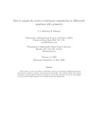
2 Identical concrete cast in impermeable (Left) and permeable<br />
(Right) moulds<br />
the construction of columns and footings4 . Additional and ongoing<br />
research5 , led by Professor Mark West at the University of<br />
Manitoba’s Centre for Architectural Structures and Technology<br />
(C.A.S.T), has further considered the architectural possibilities of<br />
<strong>fabric</strong> <strong>formwork</strong> for beams and trusses, in addition to its use for<br />
shells, panels, columns and walls (Fig 1).<br />
Although it has a low embodied energy (of approximately<br />
0.90MJ/kg) 6 concrete is used in vast quantities. In 2008 world<br />
production of cement amounted to approximately 2.8 x 10⁹t7 , with<br />
its manufacture estimated to account for some 3% of all global<br />
CO2 emissions8 , providing further impetus for the design of<br />
optimised <strong>structures</strong>. <strong>Concrete</strong> volume savings in <strong>fabric</strong> formed<br />
beams, when compared to an equivalent strength prismatic<br />
member, of 40% have already been achieved9,10 , illustrating the<br />
potential for <strong>fabric</strong> <strong>formwork</strong> to reduce the embodied energy of<br />
new building <strong>structures</strong>.<br />
Yet <strong>fabric</strong> <strong>formwork</strong> does not simply facilitate reductions in<br />
material use. Forming concrete in a permeable mould allows air<br />
and water to escape from the <strong>formwork</strong> to provide a high quality<br />
surface finish that can be readily distinguished from an identical<br />
concrete cast against an impermeable mould, as illustrated in<br />
Fig 2. Reductions in water:cement ratio towards the external face<br />
of <strong>structures</strong> cast in permeable moulds have been widely<br />
reported 11 and provide a surface zone with improved hardness<br />
12, 13<br />
and reduced porosity 14 . The resulting concrete surface is more<br />
durable than one cast against impermeable <strong>formwork</strong>, with<br />
reductions in carbonation depth, chloride ingress and oxygenation<br />
reported in the literature 11 .<br />
For <strong>structures</strong> where the concrete grade specified is governed<br />
by durability rather than strength concerns, permeable <strong>formwork</strong><br />
offers significant opportunities for embodied energy savings. For<br />
example, a C20 concrete mix cast in permeable <strong>formwork</strong> has<br />
been found to have a lower carbonation depth after 11 months<br />
than a C50 mix cast in conventional <strong>formwork</strong> 12 , with such a<br />
reduction in concrete grade providing embodied energy savings of<br />
approximately 38% 6 – in addition to those savings already<br />
achieved simply by <strong>using</strong> <strong>fabric</strong> <strong>formwork</strong> to cast a structurally<br />
optimised form. Long term cost savings for concrete cast in<br />
permeable moulds have also been reported 15 and arise primarily<br />
from a reduction in maintenance and repair requirements.<br />
Allowing water, but not cement, to drain from the surface zone is<br />
imperative when permeable <strong>formwork</strong> is used, and while Price 11<br />
suggests a maximum pore size of 50μm be specified, much<br />
greater pore sizes have been successfully used by the authors.<br />
The high quality surface finish of concrete cast in <strong>fabric</strong> further<br />
encourages the use of exposed internal concrete surfaces, the<br />
consequence of which is two-fold: extraneous wall and ceiling<br />
coverings can be omitted and the now exposed thermal mass may<br />
properly be used in the provision of thermal comfort.<br />
Design<br />
Fabric<br />
The critical aspect of <strong>fabric</strong> <strong>formwork</strong> for determining shape and<br />
therefore aesthetic is the <strong>fabric</strong> itself. Although almost any woven<br />
<strong>fabric</strong> can be used as <strong>formwork</strong> for <strong>fabric</strong> cast concrete, tensile<br />
3 Anchorage <strong>using</strong> welded end plates<br />
strengths in both warp and weft directions must be sufficient to<br />
hold the wet concrete and a low creep modulus is desirable to limit<br />
<strong>formwork</strong> deformations during casting and curing. The available<br />
literature illustrates the use of a range of <strong>fabric</strong>s as <strong>formwork</strong>,<br />
including hessian 9 and geotextiles 16 , while more recent<br />
experimental work undertaken at the University of Bath has used a<br />
woven polyester <strong>fabric</strong> that has previously been utilised in the<br />
construction of underwater concrete <strong>structures</strong>.<br />
Once a suitable <strong>fabric</strong> has been chosen, a number of methods<br />
are available to determine the final shape of the fluid filled flexible<br />
membrane. Schmitz 17 used an iterative finite element based<br />
procedure to determine the form of <strong>fabric</strong> formed wall panels,<br />
while Veenendaal 18 implemented dynamic relaxation to predict the<br />
final shape of <strong>fabric</strong> formed beams. Empirical relationships<br />
determined by Bailiss 9 provide a less rigorous solution to the same<br />
problem, but have nevertheless been used successfully 10 , while<br />
Foster 19 used a simple step-wise based method to iteratively<br />
determine the shape of the concrete filled <strong>fabric</strong>. The complete<br />
solution, which requires the use of incomplete elliptic integrals, is<br />
given separately by Iosilevskii 20 .<br />
Reinforcement<br />
The reinforcement of variable section members adds some<br />
complexity to the construction process, yet fundamentally does<br />
not differ from an orthogonal structure. The provision of end<br />
anchorage has been seen in previous work10 to be a crucial<br />
consideration and both externally welded steel plates (Fig 3) and<br />
transversely welded internal bars have been used to achieve this.<br />
The provision of transverse reinforcement in a variable section<br />
member simply requires a varying link size, which is easily<br />
achieved but can add cost to the construction process. It is<br />
therefore imperative that any reinforcement specified be used to its<br />
full capacity.<br />
Analysis<br />
Structural design procedures for bending moment shaped beams,<br />
as developed at the University of Bath9,10 , are based on a sectional<br />
approach that aims to satisfy the bending and shear requirements<br />
of the beam at every point along its length. Where open web beam<br />
sections are desired (as discussed later), additional consideration<br />
must be given to the effects of Vierendeel action in the member<br />
(detailed elsewhere21 ).<br />
Flexural strength calculations are undertaken by first dividing the<br />
element into a number of equally spaced sections. By assuming<br />
that the longitudinal steel has yielded, the lever arm distance<br />
required to provide the required moment capacity at each section<br />
is quickly determined by equilibrium, Eq.(1) and Fig 4. This is<br />
repeated at each section along the length of the member to<br />
determine the optimised reinforcement layout for a given loading<br />
envelope.<br />
z =<br />
M<br />
F<br />
Rd<br />
bH ,<br />
...(1)<br />
Where z is the lever arm, M is the applied moment and F b,H the<br />
horizontal component of tension force on the section.<br />
The Structural Engineer 89 (8) 19 April 2011 21