Violation in Mixing
Violation in Mixing
Violation in Mixing

You also want an ePaper? Increase the reach of your titles
YUMPU automatically turns print PDFs into web optimized ePapers that Google loves.
ÍÒ�Ú�Ö×�Ø�� ���Ð� ËØÙ�� �� ÌÓÖ�ÒÓ<br />
�� ÓÐØ�� �� Ë ��ÒÞ� Å�Ø�Ñ�Ø� �� ��×� �� � Æ�ØÙÖ�Ð�<br />
�ÓØØÓÖ�ØÓ �� Ê� �Ö � �Ò ��×� �<br />
�ÁÎ �� ÐÓ<br />
� �<br />
�Ò�ÐÝ×�× Ó� ØÛÓ �Ó�Ý ��ÖÑÐ�××<br />
�� �Ý× �ÓÖ �Ö�Ò ��Ò�<br />
�Ö� Ø�ÓÒ �Ò� �È Ú�ÓÐ�Ø�Ò�<br />
�×ÝÑÑ�ØÖÝ Ñ��×ÙÖ�Ñ�ÒØ× Û�Ø�<br />
Ø�� ����Ö �ÜÔ�Ö�Ñ�ÒØ<br />
Ê�Ð�ØÖ� ��<br />
ÈÖÓ� ××� �Ð�××�Ò�Ö� ÊÓÑ�ÖÓ<br />
��������<br />
�ÓØØ ××� Å�Ö �ÐÐ� �ÓÒ�
� ����Ó
Contents<br />
Introduction . ............................................. i<br />
1 �È <strong>Violation</strong> <strong>in</strong> the �� System 5<br />
1.1 È , � and Ì symmetries . . .................................. 5<br />
1.2 Neutral � Mesons ....................................... 7<br />
1.2.1 Phenomenology of the decay processes with the Wigner-Weisskopf perturbative<br />
method ....................................... 7<br />
1.2.2 The � system: general formalism . . ....................... 10<br />
1.2.3 The � system: mass eigenstates . . . ....................... 13<br />
1.2.4 Phase Conventions ................................. 15<br />
1.2.5 Time Evolution of Neutral �� Mesons ....................... 16<br />
1.2.6 Time Formalism for Coherent �� States ..................... 18<br />
1.3 The Three Types of �È <strong>Violation</strong> <strong>in</strong> � Decays . ....................... 21<br />
1.3.1 �È <strong>Violation</strong> <strong>in</strong> Decay . . . ............................ 22<br />
1.3.2 �È <strong>Violation</strong> <strong>in</strong> Mix<strong>in</strong>g . . ............................ 23<br />
1.3.3 �È <strong>Violation</strong> <strong>in</strong> the Interference Between Decays With and Without Mix<strong>in</strong>g. . . 25<br />
1.4 �È <strong>Violation</strong> <strong>in</strong> the Standard Model . ............................ 27<br />
1.4.1 The �ÃÅ Picture of �È <strong>Violation</strong> . ....................... 27<br />
1.4.2 Unitarity of the �ÃÅ Matrix ........................... 31<br />
1.4.3 Measur<strong>in</strong>g �ÃÅ Parameters with �È Conserv<strong>in</strong>g Processes ........... 35<br />
1.5 Determ<strong>in</strong>ation of « ...................................... 37<br />
1.5.1 �È <strong>Violation</strong> us<strong>in</strong>g � decays <strong>in</strong>to non �È eigenstates and Extraction of «<br />
ignor<strong>in</strong>g pengu<strong>in</strong>s ................................. 37<br />
1.5.2 Extraction of « <strong>in</strong> the Presence of Pengu<strong>in</strong>s . . . ................. 39
ii<br />
1.5.3 Hadronic charmless two-body � decays ...................... 40<br />
1.5.3.1 � � � � ............................. 41<br />
1.5.3.2 � � �à ............................... 44<br />
1.5.4 Direct �È <strong>Violation</strong> ................................ 45<br />
1.5.5 � Decays <strong>in</strong>to à à ............................... 46<br />
2 The BABAR Experiment 47<br />
2.1 Physics at � � B Factory operat<strong>in</strong>g at the § �Ë resonance ................ 47<br />
2.1.1 �È asymmetry experimental measure ....................... 47<br />
2.1.2 PEP-II. ....................................... 49<br />
2.2 The BABAR detector. ...................................... 51<br />
2.2.1 The Silicon Vertex Tracker: ËÎÌ. ......................... 53<br />
2.2.2 The drift chamber ��À. .............................. 57<br />
2.2.3 The charged particle track<strong>in</strong>g system. ....................... 60<br />
2.2.4 The Čerenkov-based detector �ÁÊ�. ....................... 63<br />
2.2.5 The electromagnetic calorimeter ��. ...................... 67<br />
2.2.6 The magnet and the muon and neutral hadron detector Á�Ê. ........... 70<br />
2.2.7 The trigger. . . . .................................. 74<br />
3 Ã Ë reconstruction and efficiency studies 77<br />
3.1 Reconstruction . ....................................... 77<br />
3.1.1 Ã Ë candidate lists available for the physics analyses ............... 77<br />
3.2 Study on MC truth ...................................... 78<br />
3.3 Studies on data . ....................................... 79<br />
MARCELLA BONA<br />
3.3.1 Data samples . . .................................. 80<br />
3.3.2 Mass and Resolution Studies ............................ 81<br />
3.3.3 Efficiency Studies ................................. 83<br />
3.3.4 Correction for the Monte Carlo efficiencies . . . ................. 88<br />
3.3.5 Run 2 data sample: first look at the Ã Ë reconstruction . . . ........... 90
4 Strategy and Tools for Charmless Two-body � Decays Analysis 97<br />
4.1 Data samples . . ....................................... 97<br />
4.2 Event selection . ....................................... 98<br />
4.2.1 Topological Variables ................................100<br />
4.2.2 � candidate selection: k<strong>in</strong>ematic Variables . . . .................102<br />
4.2.2.1 Control Sample � ¦ � � � ¦ ....................103<br />
4.3 Background fight<strong>in</strong>g . . . ..................................104<br />
4.4 PID selection . . .......................................107<br />
4.4.1 � � £ � control sample ............................107<br />
4.4.2 Selector-based PID .................................109<br />
4.5 Track<strong>in</strong>g Corrections . . . ..................................111<br />
4.6 Analysis methods .......................................111<br />
4.6.1 Sample def<strong>in</strong>itions .................................112<br />
4.6.2 Beam energy-substituted mass Ñ�Ë ........................113<br />
4.6.3 Energy difference ¡� ...............................114<br />
4.6.4 Fisher output � ...................................116<br />
4.6.5 Pion and kaon � ..................................117<br />
4.6.6 Correlations between PDFs . ............................119<br />
5 Measurement of Branch<strong>in</strong>g Fractions for � ¦ � Ã � ¦ decays 121<br />
5.1 Data samples and event selection . . . ............................121<br />
5.2 Ã Ë reconstruction .......................................122<br />
5.3 Analysis Strategy .......................................125<br />
5.4 Background Suppression and PDF Parameterization .....................126<br />
5.4.1 ¡� PDF and Def<strong>in</strong>ition of Signal and Side-band Regions . ...........126<br />
5.4.2 Parameterizations of Ñ�Ë Distributions ......................128<br />
5.4.3 Fisher Discrim<strong>in</strong>ant .................................128<br />
5.4.4 Particle ID Selection ................................129<br />
iii
iv<br />
5.4.5 Efficiency ......................................131<br />
5.5 Maximum likelihood analysis .................................132<br />
5.5.1 Correlations between PDFs . ............................134<br />
5.5.2 Event yields and asymmetries ...........................134<br />
5.5.3 Cross-check and systematics ............................135<br />
5.5.4 Systematic uncerta<strong>in</strong>ties . . ............................138<br />
5.5.5 ¡� distribution from on-resonance data ......................142<br />
5.5.6 ARGUS shape from on-resonance data ......................143<br />
5.6 Count<strong>in</strong>g analysis .......................................144<br />
5.6.1 Cuts . . .......................................144<br />
5.6.2 Results .......................................145<br />
5.7 Determ<strong>in</strong>ation of branch<strong>in</strong>g fraction . ............................146<br />
6 Measurement of Branch<strong>in</strong>g Fractions for � � Ã Ë Ã Ë Decays 149<br />
6.1 Data samples and event selection . . . ............................149<br />
6.2 Analysis strategy .......................................149<br />
6.2.1 Efficiency ......................................150<br />
6.3 The maximum likelihood analysis . . ............................150<br />
6.3.1 Def<strong>in</strong>ition of PDFs .................................151<br />
6.3.2 Test on the maximum likelihood analysis .....................156<br />
6.4 Count<strong>in</strong>g analysis .......................................157<br />
6.5 Analysis choice . .......................................159<br />
6.6 Results on the Run1 data-set .................................159<br />
6.6.1 Systematics studies .................................160<br />
6.6.2 Cross-check: the count<strong>in</strong>g analysis . . .......................162<br />
6.7 Determ<strong>in</strong>ation of the branch<strong>in</strong>g fraction ...........................162<br />
7 Analysis of the time-dependent �È -violat<strong>in</strong>g asymmetry <strong>in</strong> � � � � decays 165<br />
7.1 �È analysis requirements . ..................................165<br />
MARCELLA BONA
7.2 Branch<strong>in</strong>g fraction � � � � analysis results ......................166<br />
7.3 Analysis strategy .......................................167<br />
7.4 Data samples and event selection . . . ............................168<br />
7.4.1 Optimization of the � Ó× �Ë� cut ..........................169<br />
7.4.2 Comparison with the branch<strong>in</strong>g fraction analysis result . . . ...........172<br />
7.5 Background characterization .................................172<br />
7.5.1 Composition . . ..................................172<br />
7.5.2 Parameterization of ¡Ø ...............................173<br />
7.6 Signal characterization . . ..................................176<br />
7.7 The maximum likelihood analysis . . ............................177<br />
7.7.1 Likelihood function .................................177<br />
7.7.2 Probability Density Functions ...........................178<br />
7.7.2.1 Correlations between PDF variables .................182<br />
7.8 Validation studies .......................................185<br />
7.8.1 Toy Monte Carlo ..................................185<br />
7.8.2 Effect of float<strong>in</strong>g yields <strong>in</strong> the �È fit........................188<br />
7.8.3 Monte Carlo fits ..................................188<br />
7.8.4 Branch<strong>in</strong>g fraction fits . . . ............................190<br />
7.8.5 Lifetime and mix<strong>in</strong>g fits . . ............................190<br />
7.9 Results .............................................192<br />
7.9.1 Cross-checks . . ..................................192<br />
7.10 Systematic studies .......................................197<br />
7.11 Summary ...........................................197<br />
Bibliography .............................................205<br />
1
2<br />
MARCELLA BONA
Introduction<br />
The ma<strong>in</strong> goal of the BABAR experiment is study<strong>in</strong>g �È violation <strong>in</strong> neutral � meson decays. �È symmetry<br />
violation is an expected consequence of the Standard Model with three quark generation. The Standard<br />
Model accommodates this violation through the presence of a s<strong>in</strong>gle complex phase <strong>in</strong> the mix<strong>in</strong>g �ÃÅ<br />
matrix [2, 3]. Experimental measurements <strong>in</strong> this field are important tests of the Standard Model. �È<br />
violation has been first observed <strong>in</strong> à decays [1] <strong>in</strong> ���. Recently, the BABAR [4] and Belle experiment [5]<br />
have observed evidence of �È violation <strong>in</strong> neutral � meson decays, mak<strong>in</strong>g a �� significant measurement<br />
of the parameter ×�Ò ¬, ¬ be<strong>in</strong>g one of the angles of the Unitary Triangle.<br />
Hadronic charmless two-body � decays are important because they provide <strong>in</strong>formation on the other angles<br />
of the Unitary Triangle. In the SM the time-dependent �È -violat<strong>in</strong>g asymmetry <strong>in</strong> the channel � � � �<br />
is related to the angle «. Moreover rates asymmetries <strong>in</strong> both neutral and charged � decays <strong>in</strong>to charmless<br />
f<strong>in</strong>al states like à ¦ � § , Ã Ë � ¦ , � � ¦ (� be<strong>in</strong>g a � or a Ã) are evidence of direct �È violation. Also ratios<br />
of branch<strong>in</strong>g fractions can lead to bounds on the angle .<br />
This thesis presents measurements of branch<strong>in</strong>g fractions of the charmless two-body modes � ¦ � Ã Ë � ¦<br />
and � � Ã Ë Ã Ë and of the time <strong>in</strong>tegrated CP violat<strong>in</strong>g asymmetry <strong>in</strong> the charged � decays. In addition,<br />
a study of the the time-dependent asymmetry is performed <strong>in</strong> the channel � � � ¦ � § .<br />
The first chapter describes the theoretical background of the �È violation and physical mean<strong>in</strong>g of the<br />
measurements presented <strong>in</strong> the follow<strong>in</strong>g chapters.<br />
The second chapter is a description of the BABAR detector with details on the track<strong>in</strong>g system and the<br />
particle identification. The third chapter presents an analysis on <strong>in</strong>clusive Ã Ë reconstruction which has<br />
been performed <strong>in</strong> order to provide an estimate of the Ã Ë absolute reconstruction efficiency with the BABAR<br />
detector.<br />
The fourth chapter is an overview on the common issues of the hadronic charmless two-body analyses, while<br />
the fifth presents the actual analysis of the decay � ¦ � Ã Ë � ¦ whose result has been presented <strong>in</strong> Ref. [6].<br />
The sixth chapter describes the analysis of the decay � � Ã Ë Ã Ë [7].<br />
The seventh chapter present a prelim<strong>in</strong>ary result of the time-dependent analysis <strong>in</strong> � � � � decays<br />
together with a measurement of the rate asymmetry <strong>in</strong> � � Ã ¦ � § decays: this analysis is go<strong>in</strong>g to be<br />
published <strong>in</strong> Ref. [8].
4<br />
Introduzione<br />
L’esperimento BABAR ha come obiettivo primario lo studio della violazione di �È nel sistema dei mesoni �<br />
neutri. La violazione di �È è prevista all’<strong>in</strong>terno del Modello Standard con tre generazioni di quark. Tal<br />
violazione deriva nell’ambito del Modello Standard dalla presenza di una fase complessa nella matrice �ÃÅ<br />
di mix<strong>in</strong>g [2, 3]. Le misure sperimentali <strong>in</strong> questo campo sono importanti verifiche del Modello Standard.<br />
La violazione di �È è stata osservata per la prima volta nel decadimenti à [1] nel ���. Recentemente, gli<br />
esperimenti BABAR [4] e Belle [5] hanno trovato evidenze di violazione di �È nel sistema dei � neutri. Sono<br />
state pubblicate misure con significanze statistiche di �� del parametro ×�Ò ¬ dove ¬ è uno degli angoli del<br />
Triangolo di Unitarietà.<br />
I decadimenti adronici senza charm negli stati f<strong>in</strong>ali sono di notevole importanza perché possono essere<br />
ricondotti ad un altro angolo del Triangolo di Unitarietà. Nel MS la misura dell’asimmetria dipendente dal<br />
tempo nel canale � � � � è collegata all’angolo «. Inoltre eventualu asimmetrie nelle ampiezze di<br />
decadimento di � carichi o neutri <strong>in</strong> stati f<strong>in</strong>ali senza charm come à ¦ � ¦ , Ã Ë � ¦ , � � ¦ (essendo � un � od<br />
un Ã) sarebbero evidenze di violazione diretta di �È . Anche i rapporti tra i vari branch<strong>in</strong>g fractions posono<br />
stabilire del v<strong>in</strong>coli sull’angolo .<br />
Questa tesi presenta misure di branch<strong>in</strong>g fractions dei canali di decadimento � ¦ � Ã Ë � ¦ e � � Ã Ë Ã Ë<br />
e della asimmetria non dipendente dal tempo nei decadimenti dei � carichi. E’ stata poi sviluppata l’analisi<br />
della asimmetria dipendente dal tempo nel canale � � � ¦ � § .<br />
Il primo capitolo descrive le basi della teoria e della fenomenologia della violazione di �È ed il signifato<br />
fisico delle misure riportate nei capitoli successivi. Il secondo capitolo è una panoramica sul rivelatore di<br />
BABAR con particolare attenzione al sistema di track<strong>in</strong>g e di identificazione di particella. Il terzo capitolo<br />
presenta un’analisi sulla ricostruzione <strong>in</strong>clusiva dei Ã Ë : questa analisi ha lo scopo di fornire una misura<br />
dell’efficienza di ricostruzione dei Ã Ë con il rivelatore di BABAR.<br />
Il quarto capitolo tratta le strategie e gli strumenti di analisi comuni allo studio di tutti i decadimenti adronici<br />
senza charm, mentre il qu<strong>in</strong>to capitolo descrive <strong>in</strong> dettaglio l’analisi del canale � ¦ � Ã Ë � ¦ , il cui risultato<br />
è stato pubblicato <strong>in</strong> [6]. Il sesto capitolo espone l’analisi del decadimento � � Ã Ë Ã Ë [7].<br />
Inf<strong>in</strong>e il settimo capitolo presenta un risultato prelim<strong>in</strong>are dell’analisi dipendente dal tempo nel canale � �<br />
� � <strong>in</strong>sieme ad una misura della asimmetria nelle ampiezze di decadimento nei canali � � Ã ¦ � § :<br />
questa analisi sarà pubblicata <strong>in</strong> [8].<br />
MARCELLA BONA
1<br />
�È <strong>Violation</strong> <strong>in</strong> the �� System<br />
�È symmetry violation is an expected consequence of the Standard Model with three quark generations<br />
(see Sec. 1.4.1): as a matter of fact, the �È violation that shows up <strong>in</strong> a small fraction of weak decays is<br />
accommodated simply <strong>in</strong> the three-generation Standard Model Lagrangian. All it requires is that �È is not<br />
imposed as a symmetry.<br />
Some experiments have proved that �È violation occurs <strong>in</strong> neutral à decays [1], The Ã-decay observations,<br />
together with other measurements, place constra<strong>in</strong>ts on the parameters of the Standard Model mix<strong>in</strong>g matrix<br />
(the �ÃÅ matrix [2, 3]) but do not yet provide any test about whether the pattern of �È violation predicted<br />
by the m<strong>in</strong>imal Standard Model is the one found <strong>in</strong> nature. A multitude of �È -violat<strong>in</strong>g effects are expected<br />
<strong>in</strong> � decays, some of which are very cleanly predicted by the Standard Model.<br />
If enough <strong>in</strong>dependent observations of �È violation <strong>in</strong> � decays can be made then it will be possible to test<br />
the Standard Model predictions for �È violation. Either the relationships between various measurements<br />
will be consistent with the Standard Model predictions and fully determ<strong>in</strong>e the �ÃÅ parameters or there<br />
will be no s<strong>in</strong>gle choice of �ÃÅ parameters that is consistent with all measurements. This latter case would<br />
<strong>in</strong>dicate that there is a contribution of physics beyond the Standard Model: so the ma<strong>in</strong> goal for the BABAR<br />
experiment is to measure enough quantities to impose redundant constra<strong>in</strong>ts on Standard Model parameters,<br />
<strong>in</strong>clud<strong>in</strong>g particularly the convention-<strong>in</strong>dependent comb<strong>in</strong>ations of �È -violat<strong>in</strong>g phases of �ÃÅ matrix<br />
elements.<br />
S<strong>in</strong>ce the Standard Model accommodates �È -violation, no extension of the Standard Model can be �È -<br />
conserv<strong>in</strong>g and thus many extensions have additional sources of �È -violat<strong>in</strong>g effects, or effects which<br />
change the relationship of the measurable quantities to the �È -violat<strong>in</strong>g parameters of the Standard Model:<br />
� Factories like BABAR can play an important role <strong>in</strong> measur<strong>in</strong>g most of these parameters.<br />
1.1 È , � and Ì symmetries<br />
The fundamental po<strong>in</strong>t is that �È symmetry is broken <strong>in</strong> any theory that has complex coupl<strong>in</strong>g constants<br />
<strong>in</strong> the Lagrangian which cannot be removed by any choice of phase redef<strong>in</strong>ition of the fields <strong>in</strong> the theory.<br />
Three discrete operations are potential symmetries of a field theory Lagrangian [9]: two of them, parity<br />
and time reversal are space-time symmetries. Parity, denoted by È , sends Ø� Ü � Ø� Ü , revers<strong>in</strong>g the<br />
handedness of space. Time reversal, denoted by Ì , sends Ø� Ü � Ø� Ü , <strong>in</strong>terchang<strong>in</strong>g the forward<br />
and backward light-cones. A third (non-space-time) discrete operation is charge conjugation, denoted by<br />
�. This operation <strong>in</strong>terchanges particles and anti-particles. The comb<strong>in</strong>ation �È replaces a particle by its<br />
anti-particle and reverses momentum and helicity.
6 �È <strong>Violation</strong> <strong>in</strong> the �� System<br />
The comb<strong>in</strong>ation �ÈÌ is an exact symmetry <strong>in</strong> any local Lagrangian field theory: the �ÈÌ theorem is<br />
based on general assumptions of field theory and relativity and states that every Hamiltonian that is Lorentz<br />
<strong>in</strong>variant is also <strong>in</strong>variant under comb<strong>in</strong>ed application of �ÈÌ, even if it is not <strong>in</strong>variant under �, È and Ì<br />
separately. One of the consequences of this theorem is that particles and anti-particles should have exactly<br />
the same mass and lifetime.<br />
From experiment, it is observed that electromagnetic and strong <strong>in</strong>teractions are symmetric with respect<br />
to È , � and Ì . The weak <strong>in</strong>teractions violate � and È separately, but preserve �È and Ì to a good<br />
approximation. Only certa<strong>in</strong> rare processes, all <strong>in</strong>volv<strong>in</strong>g neutral à mesons, have been observed to exhibit<br />
�È violation. All these observations are consistent with exact �ÈÌ symmetry.<br />
The operators associated to these symmetries have different properties: È and � operators are unitary (and<br />
thus they satisfy the relation Í Ì � Í ) and l<strong>in</strong>ear (and thus Í «� � � ¬� � � � «Í� � � ¬Í���).<br />
Otherwise, Ì operator is anti-unitary, that means that is satisfies the unitary relation � Ì � � ), but it<br />
is anti-l<strong>in</strong>ear (� «� � � ¬� � � � « £ �� � � ¬ £ �� � �): because of this, Ì operator can be written as the<br />
product of two operators Íà where Í is unitary and à transforms every complex number <strong>in</strong> its conjugate.<br />
Tak<strong>in</strong>g <strong>in</strong>to account a generic fermionic state, some quantic numbers « are associated to it, together with a<br />
polarization ÂÞ and a momentum Ô: an anti-particle with same polarization and momentum have opposite<br />
quantic numbers, «. Def<strong>in</strong><strong>in</strong>g � � Ø� Ü � or � � Ô�ÂÞ �the generic fermionic state and apply<strong>in</strong>g È , � and<br />
Ì , we would get:<br />
and apply<strong>in</strong>g �È :<br />
È � � Ø� Ü � � �È � � Ø� Ü � � �È � � Ô�ÂÞ �<br />
��� Ø� Ü � � ��� � Ø� Ü � � ��� � Ô�ÂÞ �<br />
Ì�� Ø� Ü � � �Ì � � Ø� Ü � � �Ì � � Ô� ÂÞ �<br />
�È � � Ø� Ü � � ��È � � Ø� Ü � � ��È � � Ô�ÂÞ �<br />
Tak<strong>in</strong>g <strong>in</strong>to account the Lorentz <strong>in</strong>variance and hermiticity of the Lagrangian, �È transformation rules imply<br />
that each of the comb<strong>in</strong>ations of fields and derivatives that appear <strong>in</strong> the Lagrangian transforms under �È to<br />
its Hermitian conjugate. However, there are coefficients <strong>in</strong> front of these expressions which represent either<br />
coupl<strong>in</strong>g constants or particle masses and which do not transform under �È . If any of these quantities are<br />
complex, then the coefficients <strong>in</strong> front of �È -related terms are complex conjugates of each other. In such<br />
a case, �È is not necessarily a good symmetry of the Lagrangian. When the rates of physical processes<br />
that depend on these Lagrangian parameters are calculated, there can be �È -violat<strong>in</strong>g effects, namely rate<br />
differences between pairs of �È conjugate processes.<br />
MARCELLA BONA
1.2 Neutral � Mesons 7<br />
Note, however, that not all Lagrangian phases are physically mean<strong>in</strong>gful quantities. Consider the Lagrangian<br />
that conta<strong>in</strong>s the most general set of complex coupl<strong>in</strong>g constants consistent with all other symmetries <strong>in</strong> the<br />
theory. That is to say �È symmetry is not imposed and hence any coupl<strong>in</strong>g is allowed to be complex (unless<br />
the Hermitian structure of the Lagrangian automatically requires it to be real). Now any complex field <strong>in</strong><br />
the Lagrangian can be redef<strong>in</strong>ed by an arbitrary phase rotation; such rotations will not change the physics,<br />
but will change the phases of some set of terms <strong>in</strong> the Lagrangian. Some set of coupl<strong>in</strong>gs can be made real<br />
by mak<strong>in</strong>g field re-def<strong>in</strong>itions. However if any non-zero phases for coupl<strong>in</strong>gs rema<strong>in</strong> after all possible field<br />
re-def<strong>in</strong>itions have been used to elim<strong>in</strong>ate as many of them as possible, then there is �È violation. It is a<br />
matter of simple count<strong>in</strong>g for any Lagrangian to see whether this occurs. If all phases can be removed <strong>in</strong><br />
this way then that theory is automatically �È -conserv<strong>in</strong>g. In such a theory it is impossible to <strong>in</strong>troduce any<br />
�È violations without add<strong>in</strong>g fields or remov<strong>in</strong>g symmetries so that additional coupl<strong>in</strong>gs appear. (This is<br />
the case for the Standard Model with only two generations and a s<strong>in</strong>gle Higgs multiplet.) Choos<strong>in</strong>g to make<br />
certa<strong>in</strong> terms real and leave others complex has no physical mean<strong>in</strong>g and so a different choice, related to<br />
the first by field re-def<strong>in</strong>itions, has the same physical consequences: only those differences between pairs of<br />
phases that are unchanged by such re-def<strong>in</strong>itions are physically mean<strong>in</strong>gful.<br />
1.2 Neutral � Mesons<br />
There are two possible pairs of mesons <strong>in</strong>volv<strong>in</strong>g � quarks: �� mesons, made from one � type quark (or<br />
anti-quark) and one � type, and �× mesons from one � and one ×. Like the neutral à mesons, the neutral<br />
� mesons are characterized by the fact that different neutral states are relevant to the discussion of different<br />
physical processes. There are two flavor eigenstates, which have def<strong>in</strong>ite quark content and are most useful<br />
when treat<strong>in</strong>g particle production, and there are eigenstates of the Hamiltonian, namely states of def<strong>in</strong>ite<br />
mass and lifetime. Assum<strong>in</strong>g �È as a good symmetry for the weak Hamiltonian, the mass eigenstates<br />
would also be �È eigenstates which under a �È transformation would transform <strong>in</strong>to themselves with a<br />
def<strong>in</strong>ite eigenvalue ¦ . On the contrary, consider<strong>in</strong>g �È not a good symmetry, the mass eigenstates can be<br />
different from �È eigenstates. In any case the mass eigenstates are not flavor eigenstates, and so the flavor<br />
eigenstates are mixed with one another as they propagate through space. The flavor eigenstates for �� are<br />
� � �� and � � ��. The � meson is the isosp<strong>in</strong> partner of � : therefore it conta<strong>in</strong>s the � quark 1 . The<br />
conventional def<strong>in</strong>itions for the �× system are �× � �× and �× � ×�.<br />
1.2.1 Phenomenology of the decay processes with the Wigner-Weisskopf perturbative method<br />
Given a system described by a Hamiltonian À that can be written like this:<br />
À � À À<br />
1 This is similar to the à mesons, where à , the isosp<strong>in</strong> partner of à , conta<strong>in</strong>s the × quark, and the correspond<strong>in</strong>g anti-particle<br />
doublet is (Ã ,Ã ).<br />
�È VIOLATION IN THE �� SYSTEM
8 �È <strong>Violation</strong> <strong>in</strong> the �� System<br />
where À is the strong and electromagnetic Hamiltonian À � À× À�Ñ, while À is a small perturbation<br />
that represents the weak-<strong>in</strong>teraction Hamiltonian À � ÀÛ. The system governed by this Hamiltonian must<br />
be solution of the time dependent Schröd<strong>in</strong>ger equation:<br />
� �<br />
�Ø � � Ø �× � À� � Ø �×<br />
We can def<strong>in</strong>e a set of discreet eigenstates � � � and a set of eigenstates <strong>in</strong> the cont<strong>in</strong>uum � � � for which we<br />
can write:<br />
À � � � � � � � � and À � � � � ��� � �<br />
At this po<strong>in</strong>t, us<strong>in</strong>g the Schröd<strong>in</strong>ger picture, the generic system can be written like:<br />
� � Ø �× � �<br />
�<br />
«� Ø � � � �<br />
�<br />
¬� Ø � � �<br />
where � � � represent the states to which the mesons �È � and �È � (or <strong>in</strong> a more general way the states � � �)<br />
can decay. For Ø � , the generic state is:<br />
Us<strong>in</strong>g the <strong>in</strong>teraction picture, we have:<br />
� � Ø � �×� �<br />
« ����� � � Ø � �Á ��� Ø� �×� �� Ø �Á �� �À Ø � � Ø �× � �<br />
the dynamic equation be<strong>in</strong>g written:<br />
� �<br />
�Ø � � Ø �Û � À Û� � Ø �Û<br />
�<br />
�<br />
�� Ø � � � �<br />
�<br />
�� Ø � � �<br />
that depends only on the weak Hamiltonian redef<strong>in</strong>ed like À Û � � �À Ø À � �À Ø . In terms of amplitude we<br />
have:<br />
� ��� Ø<br />
�Ø<br />
MARCELLA BONA<br />
� ��� Ø<br />
�Ø<br />
�<br />
� � � �ÀÛ� � ��� Ø �<br />
� �� �� Ø ���ÀÛ�����Ø �<br />
�<br />
�<br />
� � � �� � Ø<br />
� � �ÀÛ� � ��� Ø �<br />
� ��� �� Ø<br />
���ÀÛ�����Ø (1.1)<br />
�<br />
�
1.2 Neutral � Mesons 9<br />
Apply<strong>in</strong>g the Wigner-Weisskopf method [10], we <strong>in</strong>troduce an approximation by leav<strong>in</strong>g out <strong>in</strong> Eq. 1.1,<br />
the last term: this corresponds to neglect<strong>in</strong>g the weak <strong>in</strong>teraction for those particles to which the <strong>in</strong>itial<br />
mesons can decay. Therefore the decay products are considered to be stable. With this method and with<br />
this approximation, we can write these two equations as functions of �� Ø that are a f<strong>in</strong>ite number Ò of<br />
functions. Def<strong>in</strong><strong>in</strong>g the vector:<br />
� Ø �<br />
�<br />
�<br />
�<br />
�<br />
�<br />
� Ø<br />
�<br />
�<br />
�<br />
�Ò Ø<br />
�<br />
�<br />
�<br />
�<br />
�<br />
and where Ï is def<strong>in</strong>ed as:<br />
Ï � Ï�� �<br />
� that satisfies � Ø �� �ÏØ « � where « �<br />
� ���À�� � È �<br />
���À���� � �À � � �<br />
� �� È<br />
and go<strong>in</strong>g back to the Schröd<strong>in</strong>ger picture, one obta<strong>in</strong>s:<br />
�<br />
�<br />
�<br />
�<br />
�<br />
«<br />
�<br />
�<br />
�<br />
« Ò<br />
�<br />
�<br />
�<br />
�<br />
�<br />
�<br />
� « Ø �<br />
�� È � Æ � ��<br />
�<br />
� � �À � � �� � �À � � � �<br />
(1.2)<br />
« Ø �� �� Ø � Ø �� �� ÏØ � �� �ÀØ � (1.3)<br />
where À � � Ï. This matrix À is called the non-Hermitian mass (or energy) matrix. At this po<strong>in</strong>t,<br />
One can def<strong>in</strong>e two Hermitian matrices Å � Å Ý and � Ý :<br />
Å � À À Ý<br />
��À À Ý from which one obta<strong>in</strong>s À � Å<br />
The elements of these matrices can be extracted from Eq. 1.2:<br />
Å �� � � Æ �� � � �À � � � �<br />
�� � �<br />
�<br />
�<br />
� � �À � � �� � �À � � �<br />
�<br />
� �� È<br />
�Æ � �� � � �À � � �� � �À � � �<br />
The �ÈÌ <strong>in</strong>variance guarantees the equality À�� � À�� with the state � � � that represents the charge<br />
conjugate of � � � (they both belong to the same eigenvalue): <strong>in</strong> fact, from<br />
� � �À� � � � � � � �ÈÌ �ÈÌ À �ÈÌ �ÈÌ ��� � ���ÈÌ� ���À� � � � � � �À� � ��<br />
suppos<strong>in</strong>g �ÈÌ À �ÈÌ � Àand know<strong>in</strong>g that �ÈÌ �ÈÌ � (therefore the eigenvalues can be<br />
���ÈÌ� � exclusively) and that �ÈÌ��� � ��ÈÌ���.<br />
�<br />
�È VIOLATION IN THE �� SYSTEM
10 �È <strong>Violation</strong> <strong>in</strong> the �� System<br />
Moreover one can demonstrate that, given the <strong>in</strong>variance for �È symmetry, the off-diagonal terms of Å and<br />
should be real. As a matter of fact def<strong>in</strong><strong>in</strong>g a Hermitian matrix À (which represents Å or ):<br />
� � �À� � � � � � � �È �È À �È �È � � � � ���È � � � �À� � � � ���À��� £ � (1.4)<br />
assum<strong>in</strong>g that �È À �È � À and remember<strong>in</strong>g that �È �È � (from which the eigenvalues<br />
satisfy the ���È � � ) and that �È � � � � ��È � � �.<br />
We can obta<strong>in</strong> one more constra<strong>in</strong>t if we consider aga<strong>in</strong> the �ÈÌ <strong>in</strong>variance: the off-diagonal terms of Å<br />
and have to be one the complex conjugate of the other. This can be shown us<strong>in</strong>g the generic Hermitian<br />
matrix À:<br />
� � �À� � � � � � � �ÈÌ �ÈÌ À �ÈÌ �ÈÌ ��� ����ÈÌ� ���À��� � ���À��� £<br />
where we have been us<strong>in</strong>g �ÈÌ À �ÈÌ � À and �ÈÌ��� � ��ÈÌ���.<br />
The À eigenvalues (complex <strong>in</strong> the most general case) can be written as Ñ� � � where one can demonstrate<br />
that � � : the matrix is def<strong>in</strong>ed the decay matrix. As a matter of fact, if one def<strong>in</strong>es the eigenstates ��<br />
of the non-Hermitian matrix À, the evolution <strong>in</strong> time of such a state is given by (as Eq. 1.3 shows):<br />
� Ø �� �ÀØ ���� �Ñ�Ø �Ø ��<br />
from which one can extract the probability of the <strong>in</strong>itial particle not to be decayed yet at a given time Ø:<br />
�� Ø � � � �Ø � Ý � ���<br />
This quantity depends only from � that can be considered the decay rate of the given À eigenstate ��. On<br />
the other hand, the matrix Å is called the Hermitian part of the mass matrix.<br />
1.2.2 The � system: general formalism<br />
A generic neutral meson �È � together with its anti-particle �È � 2 can be considered as a set of eigenstates<br />
of the imperturbed Hamiltonian À with eigenvalues Ñ and Ñ , respectively: assum<strong>in</strong>g that À conserves<br />
�ÈÌ, Ñ can be considered equal to Ñ and thus:<br />
À �È � � Ñ �È �� À �È � � Ñ �È ��<br />
These two states (particle and anti-particle) belong to Ñ that is the degenerate eigenvalue of À . Thus if<br />
an arbitrary l<strong>in</strong>ear comb<strong>in</strong>ation of them is considered:<br />
2 Here È and È label each neutral meson anti-meson pair.<br />
MARCELLA BONA
1.2 Neutral � Mesons 11<br />
�È � � ��È � ��È �<br />
this gives another À eigenstate. In this particular case, this state must satisfy the Schröd<strong>in</strong>ger equation<br />
where the matrix À is a ¢ matrix (together with the matrices Å and ):<br />
� �<br />
�Ø<br />
� �<br />
�<br />
� À<br />
�<br />
� �<br />
�<br />
� Å<br />
�<br />
Tak<strong>in</strong>g <strong>in</strong>to account the � system and the relation ��� � �� � �� � that satisfies:<br />
� �<br />
�Ø<br />
� �<br />
Ô<br />
� À<br />
Õ<br />
- 0<br />
B<br />
- 0<br />
B<br />
b<br />
d -<br />
b<br />
d -<br />
� � ��<br />
� Å Å<br />
�<br />
� Å £ Å<br />
�<br />
� �<br />
�<br />
(u,c) t (u,c)<br />
- -<br />
t<br />
-<br />
W -<br />
W<br />
W<br />
(u,c) t<br />
-<br />
+<br />
(u,c)<br />
- - -<br />
t<br />
W +<br />
� �<br />
�<br />
� (1.5)<br />
�<br />
£<br />
d<br />
b -<br />
d<br />
b -<br />
��� �<br />
Ô<br />
�<br />
Õ<br />
96/10/24 11.13<br />
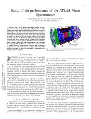
Figure 1-1. Feynman’s box diagrams describ<strong>in</strong>g � � oscillations.<br />
The off-diagonal terms should be one the complex conjugate of the other, s<strong>in</strong>ce the matrices are Hermitian.<br />
�È conservation would imply also the reality of those terms. The off-diagonal terms <strong>in</strong> these matrices, Å<br />
and , are particularly important <strong>in</strong> the discussion of �È violation: they are the dispersive and absorptive<br />
parts respectively of the transition amplitude from � to � . Å contributes to the transition amplitude<br />
from � to � through <strong>in</strong>termediate states described by box diagrams (see Fig. 1-1). The box diagrams<br />
have four vertices and so they are fourth order diagrams: <strong>in</strong> the Standard Model, they correspond to second<br />
B 0<br />
B 0<br />
�È VIOLATION IN THE �� SYSTEM
12 �È <strong>Violation</strong> <strong>in</strong> the �� System<br />
order terms with respect to «Û expansion, the weak <strong>in</strong>teraction coupl<strong>in</strong>g constant. These contributions arise<br />
from the box diagrams with two Ï exchanges: the quark contribution can come from Ù, or Ø exchanges.<br />
Theoretically the matrix element Å can be related to the squared mass of the exchanged quark Õ, to the<br />
squared mass of the � mesons and to the product ÎÕ�Î £<br />
Õ� where the Î�� terms are the �ÃÅ matrix<br />
elements (1.46). Thus, s<strong>in</strong>ce the elements ÎÙ� and Î � are strongly suppressed with respect to ÎØ� (more<br />
than how ÎØ� is suppressed with respect to ÎÙ� and Î �), and the Ø mass dom<strong>in</strong>ates on the and Ù masses,<br />
the dom<strong>in</strong>ant contribution is due to Ø exchange. Therefore we can write [11]:<br />
Š�� � � � � � �<br />
�<br />
� �ÎØ�ÎØ�℄<br />
� ÑØ Ñ � Ñ � ÐÒ Ñ Ø<br />
Ñ �<br />
� Ç Ñ � Ñ � �<br />
Ñ Ø<br />
where �� is the Fermi constant for the weak <strong>in</strong>teraction when considered po<strong>in</strong>t-like and �� is a constant<br />
called � decay constant which rules the purely leptonic decays and represents the probability of the two<br />
constituent quarks to annihilate. Thanks to the fact that the QCD effective coupl<strong>in</strong>g constant becomes<br />
smaller <strong>in</strong> the processes where high values of momentum are transferred (if we call � the transferred<br />
momentum, this happens for � � £É�� where £É�� is a typical scale for QCD <strong>in</strong>teraction), these quark<br />
diagrams are, to a good approximation, the ma<strong>in</strong> contribution to Å , accord<strong>in</strong>g to the Standard Model.<br />
£É�� � � ��Î corresponds to the order of magnitude accord<strong>in</strong>g to which one can dist<strong>in</strong>guish the small<br />
coupl<strong>in</strong>g constant region from the strong coupl<strong>in</strong>g constant region, the latter be<strong>in</strong>g non-perturbative: if the<br />
quark É mass satisfy the ÑÉ � £É��, É is then called a heavy quark. Accord<strong>in</strong>g to this criterion, quarks<br />
Ù, � and × are light quarks, while , � and Ø are heavy. For heavy quarks, the effective coupl<strong>in</strong>g constant<br />
«× ÑÉ is small, so strong <strong>in</strong>teractions can be considered perturbative and can be treated <strong>in</strong> a similar way<br />
as we do with the electromagnetic <strong>in</strong>teractions. In the � system, long-distance contributions are expected to<br />
be negligible (unlike <strong>in</strong> the à system), so that a good approximation is tak<strong>in</strong>g <strong>in</strong>to account only the lead<strong>in</strong>g<br />
orders of the expansion with respect to the strong coupl<strong>in</strong>g.<br />
The matrix can be related to the decay amplitude of the À eigenstates: it describes the processes that rule<br />
the meson decay. The off-diagonal element represents the absorptive part of processes like � � � �<br />
� and � � � � � , where � is an on-shell <strong>in</strong>termediate state. In the case of decays through on-shell<br />
Figure 1-2. � � mix<strong>in</strong>g through virtual <strong>in</strong>termediate states (Å ) or through on-shell <strong>in</strong>termediate states<br />
( ).<br />
<strong>in</strong>termediate states, the top quark cannot contribute (because of the energy conservation) and so the lead<strong>in</strong>g<br />
contribution becomes the term conta<strong>in</strong><strong>in</strong>g the mass � of the � mesons. Theoretically, one obta<strong>in</strong>s the<br />
expression [11]:<br />
MARCELLA BONA<br />
�<br />
(1.6)
1.2 Neutral � Mesons 13<br />
�� �� ��� �<br />
� �� � Ñ<br />
¡ Ñ�<br />
�<br />
� �<br />
� �Î �Î �℄ Ñ� �<br />
Ñ<br />
Ñ �<br />
Ñ �<br />
�<br />
�<br />
� Ñ<br />
�<br />
Ñ� � Ñ<br />
� � �<br />
�Î �Î �℄�ÎÙ�ÎÙ�℄ ¡<br />
�ÎÙ�ÎÙ�℄ Ñ � � (1.7)<br />
that conta<strong>in</strong>s the contributions of and Ù. Us<strong>in</strong>g one of the unitary relation of the �ÃÅ matrix (see<br />
Sec. 1.4.2), it can be simplified <strong>in</strong>to [11]:<br />
�� �� ��Ñ� � � �ÎØ�ÎØ�℄ Ñ� �Î�Î �℄�ÎØ�ÎØ�℄Ñ Ç<br />
��<br />
�<br />
� So now the lead<strong>in</strong>g term is the one conta<strong>in</strong><strong>in</strong>g mass �, that is of the same order of the mass � of quark<br />
�: talk<strong>in</strong>g about orders of magnitude, we can write:<br />
This allows to write also:<br />
� �� �<br />
�Å �� � � Ñ � �ÎØ�ÎØ�℄<br />
Ñ Ø �ÎØ�ÎØ�℄ � Ñ �<br />
Ñ Ø<br />
This relation is crucial for the � system and it will be used <strong>in</strong> Sec. 1.2.5.<br />
1.2.3 The � system: mass eigenstates<br />
�<br />
��<br />
� (1.8)<br />
� �� ���Š�� �� (1.9)<br />
The states with def<strong>in</strong>ite mass and lifetime are eigenstates of the whole Hamiltonian À and they can be<br />
written like �Ä (the lighter) and �À (the heavier), l<strong>in</strong>ear comb<strong>in</strong>ation of the � flavour eigenstates:<br />
��Ä� � Ô �� � Õ �� �<br />
��À� � Ô �� � Õ�� �<br />
with the normalization condition: �Õ� �Ô� � � (1.10)<br />
where Ô and Õ are complex coefficients. Be<strong>in</strong>g these eigenstates of À, they correspond to two eigenvalues<br />
that can be written as:<br />
�Ä�À � ÅÄ�À<br />
� Ä�À�<br />
eigenvalues of ��Ä� and ��À�, respectively. The mass difference ¡Ñ� and the width difference ¡ �<br />
between the neutral � mesons are def<strong>in</strong>ed as follows:<br />
�È VIOLATION IN THE �� SYSTEM
14 �È <strong>Violation</strong> <strong>in</strong> the �� System<br />
¡Ñ� � ÅÀ ÅÄ� ¡ � � À Ä�<br />
so that ¡Ñ� is positive by def<strong>in</strong>ition and so that, through those def<strong>in</strong>itions, one can also def<strong>in</strong>e the difference<br />
between eigenvalues �Ä�À:<br />
¡� � ¡Ñ�<br />
� ¡ �� (1.11)<br />
Go<strong>in</strong>g back to the Schröd<strong>in</strong>ger equation (1.5), one can extract the eigenvalues �Ä�À and from these, one can<br />
also obta<strong>in</strong> constra<strong>in</strong>ts for the weights Ô and Õ as functions of the Hamiltonian matrix elements:<br />
� À À<br />
À À<br />
from this, for the two eigenvalues one gets:<br />
�Ä � À À Õ<br />
Ô<br />
Ô � À À Õ<br />
�À � À À Õ<br />
Ô<br />
� À À Ô<br />
Õ<br />
�� � � �<br />
Ô<br />
Ô<br />
��Ä�À �<br />
¦Õ<br />
¦Õ<br />
and thus the relation:<br />
Look<strong>in</strong>g at the difference ¡�, the diagonal term À vanishes and one gets:<br />
Now squared:<br />
¡� �¡Ñ�<br />
¡� � ¡Ñ� � ¡ � �¡Ñ�¡ � ��À<br />
� �<br />
Õ À<br />
�<br />
Ô À<br />
� (1.12)<br />
�<br />
¡ � � À Õ<br />
� (1.13)<br />
Ô<br />
� �<br />
Õ À<br />
��À<br />
Ô À<br />
��À À �<br />
where, to get to the last equalities, Eqs. 1.12 has been used. Now from the latter expression, one obta<strong>in</strong>s:<br />
��<br />
¡Ñ� � Ê� Å<br />
��<br />
¡ � � � ÁÑ Å<br />
�<br />
�<br />
�� Å £<br />
�� Å £<br />
By substitut<strong>in</strong>g the elements of the matrix À with the elements of the two matrices Å and , one can split<br />
¡� <strong>in</strong> its real and imag<strong>in</strong>ary parts:<br />
MARCELLA BONA<br />
� £<br />
� £<br />
�� �<br />
�� �
1.2 Neutral � Mesons 15<br />
�<br />
¡� �� Å<br />
from which one obta<strong>in</strong>s:<br />
�<br />
�� Å £<br />
� £<br />
� �<br />
�� �Š� � �<br />
�<br />
� Å £ Å £<br />
¡Ñ� � ¡ � ���Å � � � � � (1.14)<br />
¡Ñ�¡ � � � Å £ Å £ ℄��Ê�Å £<br />
From the expressions 1.12, 1.11 and 1.13, one can rewrite the Õ�Ô ratio:<br />
Õ<br />
Ô<br />
� ¡�<br />
À � ¡Ñ� � ¡ �<br />
Å �<br />
Also the time-dependent Schröd<strong>in</strong>ger equation becomes:<br />
and thus the solutions are<br />
� �<br />
where Ø is the proper time of the �Ä�À meson.<br />
1.2.4 Phase Conventions<br />
�Ø<br />
�<br />
�Ä�À � ÑÄ�À<br />
� (1.15)<br />
� Å £ � £<br />
� (1.16)<br />
�<br />
¡Ñ� ¡ �<br />
� Ä�À<br />
�Ä�À � �� �ÅÄ�À Ø � Ä�À Ø<br />
� �Ä�À<br />
The states � and � , as already shown <strong>in</strong> the previous section (Eq. 1.4), are related through �È transformation:<br />
�È �� � � � ��� �� � �È �� � � � ��� �� �� (1.17)<br />
The phase �� is arbitrary s<strong>in</strong>ce flavour conservation is a symmetry of the strong <strong>in</strong>teractions and a phase<br />
transformation [12]<br />
�� � � � � �� �� � �� � � � � �� �� �� (1.18)<br />
has no physical effects. In the new basis, �È transformations take the form:<br />
�È �� � � � � � �� � ��� � �È �� � � � � � �� � ��� �<br />
�È VIOLATION IN THE �� SYSTEM<br />
�
16 �È <strong>Violation</strong> <strong>in</strong> the �� System<br />
and the various quantities def<strong>in</strong>ed change as:<br />
Å � � � �� Å � � � �� Õ�Ô � � � �� Õ�Ô � (1.19)<br />
Also decay amplitudes are affected by the phase transformation <strong>in</strong> 1.18:<br />
�� � � � �À�� �<br />
�� � � � �À�� �<br />
�� � � � �� ��<br />
�� � � � �� ��<br />
(1.20)<br />
where ��� is the physical f<strong>in</strong>al state. From transformation <strong>in</strong> 1.18, and the transformation of Õ�Ô <strong>in</strong> 1.19, one<br />
gets:<br />
��Ä�� � � �� ��Ä� ��À�� � � �� ��À�� (1.21)<br />
s<strong>in</strong>ce one can always def<strong>in</strong>e the ratio Ô ��Ô as a pure phase. As a matter of fact only the ratio Õ�Ô and its<br />
transformation are def<strong>in</strong>ed and one can write � Ô ��Ô℄� �� � � �� . Therefore equations 1.21 mean that both<br />
the eigenstates are rotated by a common phase factor with no physical mean<strong>in</strong>g.<br />
Similar phase freedom exists <strong>in</strong> def<strong>in</strong><strong>in</strong>g the �È transformation law for a possible f<strong>in</strong>al state � and its �È<br />
conjugate � ��� �: the quantity �� depends on the flavour content of � and is related to the quark flavour<br />
symmetries ( � � � �) of the strong <strong>in</strong>teractions.<br />
However, the freedom <strong>in</strong> def<strong>in</strong><strong>in</strong>g the phase of the flavour eigenstates (which are def<strong>in</strong>ed through strong<br />
<strong>in</strong>teractions only) does not mean that the full Lagrangian, which <strong>in</strong>volves also weak <strong>in</strong>teractions, is <strong>in</strong>variant<br />
under such phase re-def<strong>in</strong>itions. Indeed, the differences of flavour redef<strong>in</strong>ition phases appear as changes<br />
<strong>in</strong> the phases of the quark mix<strong>in</strong>g matrix elements and of the Yukawa coupl<strong>in</strong>gs of quarks to Higgs fields<br />
(or any other Lagrangian terms that cause coupl<strong>in</strong>gs between different flavour eigenstates <strong>in</strong> more general<br />
models).<br />
While both Õ�Ô and �� acquire overall phase re-def<strong>in</strong>itions when these phase rotations are made, the<br />
quantity:<br />
� � Õ<br />
Ô<br />
has a convention <strong>in</strong>dependent phase that has physical mean<strong>in</strong>g.<br />
1.2.5 Time Evolution of Neutral � � Mesons<br />
��<br />
��<br />
(1.22)<br />
The two neutral �� mesons are expected to have difference <strong>in</strong> lifetime at the level of Ç (see Sec. 1.2.2):<br />
¡ �� has not been measured yet, but from general considerations it can be considered negligible with<br />
respect to �� . As a matter of fact, the difference <strong>in</strong> width is produced by decay channels common to �<br />
MARCELLA BONA
1.2 Neutral � Mesons 17<br />
and � and the branch<strong>in</strong>g ratios for such channels are at or below the level of : s<strong>in</strong>ce various channels<br />
contribute with differ<strong>in</strong>g signs, their sum is not expected to exceed the <strong>in</strong>dividual level so ¡ �� � �� is<br />
a rather safe and model <strong>in</strong>dependent assumption [13]. On the other hand, ¡Ñ�� has been measured [14].<br />
¡ ��� �� � Ç<br />
� �� ¦ �<br />
Ü� � ¡Ñ�� � ��<br />
Equations 1.23 imply that, to Ç accuracy, Eqs. 1.14, 1.15 and 1.16 simplify <strong>in</strong>to:<br />
¡Ñ� �Å �<br />
¡ � Ê� Å £ ��Å �<br />
Õ�Ô �Å ��Å<br />
¡ � � ¡Ñ�� (1.23)<br />
Any � state can then be written as a comb<strong>in</strong>ation of the states �À and �Ä, and the amplitudes of this<br />
comb<strong>in</strong>ation evolve <strong>in</strong> time as<br />
�À Ø ��À � �ÅÀ Ø � À Ø<br />
�Ä Ø ��Ä � �ÅÄØ � ÄØ �<br />
A state which is created at time Ø � as <strong>in</strong>itially pure � , is denoted �� Ô�Ý× �: it has �Ä � �À �<br />
� Ô . Similarly an <strong>in</strong>itially pure � can be called �� Ô�Ý×�, and has �Ä � �À � � Õ . The time<br />
evolution of these states is thus given by<br />
where<br />
� Ø �� �ÅØ � Ø� Ó× ¡Ñ� Ø�<br />
� Ø �� �ÅØ � Ø� � ×�Ò ¡Ñ� Ø�<br />
Å � ÅÀ ÅÄ<br />
� À Ä À Ä<br />
�� Ô�Ý× Ø � � � Ø �� � Õ�Ô � Ø �� � (1.24)<br />
�� Ô�Ý× Ø � � Ô�Õ � Ø �� � � Ø �� �� (1.25)<br />
remember<strong>in</strong>g equations 1.23. Furthermore, it is useful to go beyond the lead<strong>in</strong>g approximation for the ratio<br />
, from Eqs. 1.12 the relevant expression is:<br />
Õ<br />
Ô<br />
Õ<br />
Ô �<br />
�<br />
Å £ � £<br />
�<br />
Å<br />
and the first two orders of the expansion are<br />
�<br />
�<br />
Å £<br />
�<br />
Å<br />
� �<br />
�<br />
� £<br />
� Å £<br />
�� �<br />
�<br />
�<br />
�<br />
Å<br />
��<br />
�È VIOLATION IN THE �� SYSTEM
18 �È <strong>Violation</strong> <strong>in</strong> the �� System<br />
From Eqs. 1.12 and 1.9, one can then deduce that<br />
is a good approximation.<br />
Õ<br />
Ô<br />
Å £ � �<br />
� ÁÑ<br />
�Š�<br />
Å<br />
¬<br />
¬<br />
¬ Õ<br />
Ô¬<br />
�<br />
1.2.6 Time Formalism for Coherent �� States<br />
�� � (1.26)<br />
In an � � collider operat<strong>in</strong>g at the § �Ë resonance (called a � factory, see the follow<strong>in</strong>g chapter 2), the<br />
� and � mesons produced from the decay of the § are <strong>in</strong> a coherent Ä � state. The § �Ë is a resonant<br />
� � state with quantum numbers  � � and it can decay <strong>in</strong>to � � or � � pairs: � mesons are<br />
scalars (Â È � ) and so, because of the total angular momentum conservation, the � � pair has to be<br />
produced <strong>in</strong> a Ä � state. S<strong>in</strong>ce the § �Ë decays strongly, � mesons are produced <strong>in</strong> the two flavour<br />
eigenstates � and � .<br />
After the production, one can imag<strong>in</strong>e that each of the two particles evolve <strong>in</strong> time as described above for<br />
a s<strong>in</strong>gle �. However they evolve <strong>in</strong> phase, so that at any time there is always exactly one � and one �<br />
present, at least until one particle decays. As a matter of fact, if at a given time Ø one � could oscillate<br />
<strong>in</strong>dependently from the other, they could become a state made up of two identical mesons: but this cannot<br />
happen s<strong>in</strong>ce the Ä � state is anti-symmetric, while a system of two identical mesons (that are bosons)<br />
must be completely symmetric for the two particle exchange, However once one of the particles decays the<br />
other cont<strong>in</strong>ues to evolve, and thus there are possible events with two � or two � decays, whose probability<br />
is governed by the time between the two decays.<br />
Identify<strong>in</strong>g the two particles from the § �Ë decay by the angle � that they form with the � beam direction<br />
<strong>in</strong> the § �Ë rest frame (and thus call<strong>in</strong>g them a backward and a forward �), the two-� state can be written<br />
as [12]:<br />
Ë Ø� �Ø� � Ô �<br />
�Š� �<br />
Ò � Ø� ���� � Ø��� �� � �<br />
� � ���� � ��� �� � �<br />
Ó ×�Ò � (1.27)<br />
where � is the proper time of the ��, the � particle <strong>in</strong> the forward half-space at angle �� ��� ��� and<br />
� is the proper time for the backward-mov<strong>in</strong>g ��, at � �� ��� �).<br />
In Eq. 1.27, it has been taken <strong>in</strong>to account that the § �Ë is a spatially asymmetric state (it is a parity<br />
eigenstate with eigenvalue ) and it is a � eigenstate with eigenvalue . Therefore also the system<br />
to which it decays, must be spatially anti-symmetric as well as charge-conjugation anti-symmetric at a<br />
MARCELLA BONA
1.2 Neutral � Mesons 19<br />
given time (Ø� � Ø�): <strong>in</strong> this case (a particle-anti-particle state), È and � transformations correspond to the<br />
same one. As a matter of fact, through parity � �� � goes to � � �� � � and therefore the state<br />
� �� � � � �� � � � �� � � � �� � � results <strong>in</strong> a spatially anti-symmetric one. As a<br />
consequence, the spatial contribution com<strong>in</strong>g from the Ä � condition <strong>in</strong> the spherical functions � Ñ<br />
� must<br />
result symmetric: ×�Ò � has been <strong>in</strong>cluded. On the other hand, by apply<strong>in</strong>g �, � �� � goes <strong>in</strong>to � �� �<br />
so that the state <strong>in</strong> the Eq. 1.27 is asymmetric for particle-antiparticle exchange as requested by the negative<br />
� eigenvalue of the § �Ë .<br />
S<strong>in</strong>ce the coherent time evolution of the two particles can be treated like a s<strong>in</strong>gle particle evolution, <strong>in</strong><br />
equations 1.24 and 1.25 one can substitute<br />
� Ø��� � � Ô�Ý× Ø���<br />
� Ø��� � � Ô�Ý× Ø��� �<br />
After this substitution, Eq. 1.27 can be written extract<strong>in</strong>g the time dependence (and us<strong>in</strong>g addiction and<br />
subtraction trigonometric rules):<br />
Ë Ø� �Ø� � Ô �<br />
�Š� �<br />
� ¡Ñ� Ø� Ø�<br />
�×�Ò<br />
�� Ô<br />
Õ���� Ò � ¡Ñ� Ø� Ø�<br />
Ó×<br />
�� �<br />
���� ���� Õ<br />
Ô��� �Ó<br />
� ×�Ò �� � (1.28)<br />
S<strong>in</strong>ce the �’s have equal (though back-to-back) momenta <strong>in</strong> the center-of-mass frame, before the decay of<br />
the first of the two �’s, Ø� is equal to Ø� and Eq. 1.28 conta<strong>in</strong>s one � and one � . However decay stops the<br />
clock for the decayed particle so the terms that depend on ×�Ò�¡Ñ� Ø� Ø� � ℄ beg<strong>in</strong> to play a role. From<br />
Eq. 1.28 one can derive the amplitude for decays where one of the two �’s decays to any state � at time Ø<br />
and the other decays to � at time Ø :<br />
� Ø �Ø � Ô �<br />
�Å Ø Ø � Ø �Ø<br />
�×�Ò<br />
�<br />
¡Ñ� Ø Ø �� Ô<br />
� � Õ<br />
Ò �<br />
¡Ñ� Ø Ø<br />
Ó×<br />
�� � � � �<br />
Õ<br />
� � Ô<br />
�<br />
�Ó ×�Ò � � (1.29)<br />
where �� is the amplitude for a � to decay to the state ��, �� is the amplitude for a � to decay to the same<br />
state �� (see Eqs. 1.20). To keep signs consistent with Eq. 1.28, the symbol<br />
� Ø �Ø �<br />
�<br />
Ø � Ø� � Ø � Ø�,<br />
Ø � Ø�� Ø � Ø�<br />
is <strong>in</strong>troduced, but this overall sign factor will disappear <strong>in</strong> the rate. Any state that identifies the flavor of the<br />
parent � (tagg<strong>in</strong>g) has either �� or �� � . In Eq. 1.29, the sum � � rema<strong>in</strong>s only <strong>in</strong> the factorized<br />
exponential and is vanished from ×�Ò� or Ó×�Ò� arguments.<br />
�È VIOLATION IN THE �� SYSTEM
20 �È <strong>Violation</strong> <strong>in</strong> the �� System<br />
The time dependent rate for produc<strong>in</strong>g the comb<strong>in</strong>ed f<strong>in</strong>al states � �� (apply<strong>in</strong>g trigonometric rules like<br />
Werner’s and duplication ones) is then:<br />
Ê Ø �Ø ���<br />
Ó× ¡Ñ� Ø Ø<br />
Ø Ø<br />
×�Ò ¡Ñ� Ø Ø<br />
�� �� � �� �<br />
�� �� � �� �<br />
� �<br />
Õ<br />
ÁÑ<br />
Ô �£ �<br />
�� �� � �� �<br />
�� �� � �� �<br />
� � �� � �� �<br />
�<br />
�<br />
� �<br />
Õ<br />
��<br />
Ô �£ �<br />
�<br />
Õ<br />
�ÁÑ<br />
Ô �£ �<br />
� �� � �� �<br />
� �<br />
Õ<br />
�<br />
Ô �£ �<br />
� �<br />
Õ<br />
ÁÑ<br />
� ÁÑ<br />
Ô �£ �<br />
� Õ<br />
Ô �£ �<br />
where an <strong>in</strong>tegral over all directions for both �s has been performed, so the angular dependence has<br />
been removed from the expressions, and an overall normalization factor � has been <strong>in</strong>troduced. The<br />
approximation �Õ�Ô� � has also been used.<br />
In order to measure �È asymmetries, one can look for events where one � decays to a f<strong>in</strong>al �È eigenstate<br />
��È at time Ø�, while the second decays to a tagg<strong>in</strong>g mode, that is a mode which identifies its �-flavor, at<br />
time ØØ��. For example, one can consider a tagg<strong>in</strong>g mode with � � , � ��Ø��. This identifies the other<br />
�-particle as a � at time Ø � ØØ�� at which the tagg<strong>in</strong>g decay occurs. This is true even when the tag decay<br />
occurs after the �È eigenstate decay: <strong>in</strong> this case the state of the other � at any time Ø� �ØØ�� must be just<br />
that mixture that, if it had not decayed, would have evolved to become a � at time Ø� � ØØ��. The double<br />
time expression reduces to the form:<br />
where def<strong>in</strong><strong>in</strong>g<br />
Ê Ø��È �ØØ�� � �� ØØ�� Ø� �È<br />
Ó× �¡Ñ� Ø��È ØØ�� ℄<br />
×�Ò �¡Ñ� Ø��È ØØ�� ℄<br />
���È<br />
Ò�<br />
����È � ����È �<br />
Õ<br />
�<br />
Ô<br />
and substitut<strong>in</strong>g it <strong>in</strong> the expression 1.30, one obta<strong>in</strong>s:<br />
MARCELLA BONA<br />
�<br />
����È � ����È� � �<br />
Õ<br />
ÁÑ Ô�£ �È ��È<br />
���È<br />
���È<br />
� �����<br />
�� �����<br />
�� � �����<br />
Ê Ø��È �ØØ�� � �� ØØ�� Ø� ¨<br />
�È ��Ø��� ����È � ����È� Ó× �¡Ñ� Ø��È ØØ��<br />
¡<br />
℄ ����È� ×�Ò �¡Ñ� Ø��È ØØ�� ℄ ÁÑ ���È<br />
� �<br />
�<br />
�Ó<br />
�<br />
��<br />
���<br />
(1.30)<br />
(1.31)<br />
(1.32)
1.3 The Three Types of �È <strong>Violation</strong> <strong>in</strong> � Decays 21<br />
In case the tag f<strong>in</strong>al state has � � , � ��Ø��, which identifies the second particle as a � at time ØØ��,<br />
an expression similar to Eq. 1.32 applies, except that the signs of both the cos<strong>in</strong>e and the s<strong>in</strong>e terms are<br />
reversed. The fact that �Õ�Ô� � means that the amplitudes for the two opposite tags are the same. Thus the<br />
difference of these rates divided by their sum, which measures the time-dependent �È asymmetry, is given<br />
by<br />
���È � Ê � � �� ��Ø�� Ê � � �Ø��� � �<br />
Ê � � �� ��Ø�� Ê � ��Ø��� � �<br />
�<br />
����È� ¡ Ó× ¡Ñ�Ø ÁÑ���È<br />
����È� ×�Ò ¡Ñ�Ø<br />
(1.33)<br />
where Ø � Ø��È ØØ��. The above expressions has lost its dependence from the variable Ø Ø or Ø�È ØØ��:<br />
this means that now one can fit the dependence on the variable Ø Ø without hav<strong>in</strong>g to measure the § decay<br />
time. This can be done also from equation 1.32 that can be <strong>in</strong>tegrated over the variable Ø Ø , substitut<strong>in</strong>g<br />
the variables Ì � Ø Ø and Ø � Ø Ø and <strong>in</strong>tegrat<strong>in</strong>g over Ì which for Ø � and Ø � can take<br />
values between �Ø� and <strong>in</strong>f<strong>in</strong>ity. This way, one gets an expression of Ê Ø which is only a function of the<br />
time difference Ø�È ØØ�� and not of the § decay time:<br />
¡ ¨<br />
����È �<br />
Ê Ø��È ØØ�� � �ØØ�� Ø��È �<br />
¡ (1.34)<br />
©<br />
�<br />
����È � ¡ Ó× �¡Ñ� Ø��È ØØ�� ℄ ×�Ò �¡Ñ� Ø��È ØØ�� ℄ ÁÑ ���È<br />
The fact that the variable Ø Ø can be related to the distance between the decay vertices of the two �’s<br />
is the ma<strong>in</strong> reason for build<strong>in</strong>g an energy-asymmetric collider for this k<strong>in</strong>d of measurements (see Sec. 2.1).<br />
By <strong>in</strong>tegrat<strong>in</strong>g also over this variable, all <strong>in</strong>formation on the coefficient of ×�Ò ¡Ñ� Ø Ø would be<br />
lost and the experiment would be sensitive only to those �È -violat<strong>in</strong>g effects that give ��� �� . This is a<br />
consequence of the coherent production of the two � states: <strong>in</strong> a hadronic environment, where the �’s are<br />
produced <strong>in</strong>coherently, time-<strong>in</strong>tegrated rates are always <strong>in</strong>tegrals from Ø � to <strong>in</strong>f<strong>in</strong>ity so that they reta<strong>in</strong><br />
<strong>in</strong>formation about the ×�Ò ¡Ñ�Ø term.<br />
1.3 The Three Types of �È <strong>Violation</strong> <strong>in</strong> � Decays<br />
�È violation can manifest itself <strong>in</strong> three different ways:<br />
¯ �È violation <strong>in</strong> decay: also called direct �È violation, it occurs when a decay and its �È conjugate<br />
process have different amplitudes. It can be studied <strong>in</strong> both charged and neutral decays.<br />
¯ �È violation <strong>in</strong> mix<strong>in</strong>g: also called <strong>in</strong>direct �È violation, it occurs when mix<strong>in</strong>g provides <strong>in</strong>terfer<strong>in</strong>g<br />
amplitudes. In this case, the two neutral mass eigenstates cannot be �È eigenstates too.<br />
�È VIOLATION IN THE �� SYSTEM
22 �È <strong>Violation</strong> <strong>in</strong> the �� System<br />
¯ �È violation <strong>in</strong> the <strong>in</strong>terference between mix<strong>in</strong>g and decay: it occurs <strong>in</strong> decays <strong>in</strong>to f<strong>in</strong>al states that<br />
are common to � and � . It often occurs <strong>in</strong> comb<strong>in</strong>ation with the other two types but there are cases<br />
when, to a very good approximation, it is the only effect.<br />
1.3.1 �È <strong>Violation</strong> <strong>in</strong> Decay<br />
In order to study this type of �È violation, for any f<strong>in</strong>al state �, the quantity � � �<br />
� is def<strong>in</strong>ed s<strong>in</strong>ce it is<br />
��<br />
<strong>in</strong>dependent of phase conventions and physically mean<strong>in</strong>gful. There are two types of phases that may<br />
appear <strong>in</strong> the amplitudes: complex parameters <strong>in</strong> any Lagrangian term that contributes to the amplitude<br />
will appear <strong>in</strong> complex conjugate form <strong>in</strong> the �È conjugate amplitude. Therefore these phases appear <strong>in</strong><br />
�� and � with opposite signs. In the Standard Model these phases appear <strong>in</strong> the �ÃÅ matrix and are<br />
�<br />
called weak phases. The weak phase of any s<strong>in</strong>gle term is dependent on the convention, but the difference<br />
between the weak phases <strong>in</strong> two different terms <strong>in</strong> the amplitudes is convention <strong>in</strong>dependent. A second type<br />
of phase can appear even when the Lagrangian is real: such phases come from the possible contribution<br />
from <strong>in</strong>termediate on-shell states dom<strong>in</strong>ated by strong <strong>in</strong>teractions and so they are called strong phases.<br />
S<strong>in</strong>ce strong <strong>in</strong>teractions conserve �È these phases appear <strong>in</strong> �� and �� with the same sign. Aga<strong>in</strong> only<br />
the relative strong phases of different terms have physical mean<strong>in</strong>g.<br />
Contributions to the amplitudes can be factorized as:<br />
- the magnitude ��;<br />
- the weak phase term � ��� ;<br />
- the strong phase term � �� .<br />
If several amplitudes contribute to � � �, the amplitude �� (see Eq. 1.20) and the �È conjugate amplitude<br />
� � are given by:<br />
�� � �<br />
��� � � �� � �� � � � �� �� �<br />
��� � � �� � (1.35)<br />
�<br />
where �� and �� are def<strong>in</strong>ed <strong>in</strong> expressions like 1.17: �È �� � � � ��� �� � and �È � � � � � ��� � � �<br />
(one should consider the complex conjugate of the latter expression � � � �È � � ��� � � �). If � is a �È<br />
eigenstate then � ��� � ¦ be<strong>in</strong>g its �È eigenvalue. The convention-<strong>in</strong>dependent quantity is then<br />
¬<br />
�� ¬ � ¬ � � �� ��<br />
��<br />
¬<br />
¬<br />
È � ��� � Æ� ��<br />
È � ��� � Æ� ��<br />
¬<br />
�<br />
¬ � (1.36)<br />
�È is conserved <strong>in</strong> decays when the magnitude of this ratio is , that means the rate of the decay must be<br />
equal to the rate of the �È conjugate decay. This can happen only if all weak phases �� are the same phase<br />
or if all the strong phases � are the same one. Therefore, from Eq. 1.36 one sees that<br />
MARCELLA BONA
1.3 The Three Types of �È <strong>Violation</strong> <strong>in</strong> � Decays 23<br />
¬<br />
�� ¬ �<br />
��<br />
¬<br />
¬<br />
¬� � �� ��<br />
¬ � �<br />
Instead �È is violated <strong>in</strong> decays if both the weak phases �� and the strong ones Æ� are different one from the<br />
others. In this case the ratio cannot be reduce to a pure phase:<br />
¬<br />
�� ¬ �� � �ÈÚ�ÓÐ�Ø�ÓÒ� (1.37)<br />
��<br />
¬<br />
This type of �È violation is here called �È violation <strong>in</strong> decay. It is often also called direct �È violation.<br />
It results from the �È -violat<strong>in</strong>g <strong>in</strong>terference among various terms <strong>in</strong> the decay amplitude. From Eq. 1.36 it<br />
can be shown that, <strong>in</strong> this case, �È violation requires at least two terms that have different weak phases and<br />
different strong phases:<br />
��� ��� �<br />
�<br />
���<br />
���� ×�Ò �� �� ×�Ò Æ� Æ� �<br />
Any �È asymmetries <strong>in</strong> charged � decays are from �È violation <strong>in</strong> decay. One can redef<strong>in</strong>e:<br />
�� � � � � � � �<br />
� � � � �� �<br />
from which, <strong>in</strong> terms of the decay amplitudes, one has:<br />
�� � �����<br />
�����<br />
The latter expression can be useful for neutral � mesons also: as a matter of fact �È violation <strong>in</strong> decays<br />
can also occur for neutral meson decays, where it competes with the other two types of �È violation effects<br />
described below. S<strong>in</strong>ce the amplitudes differ from their �È conjugate ones at most for a phase factor, <strong>in</strong><br />
case only one amplitude contributes to a given decay process, no direct �È violation effect can be observed.<br />
1.3.2 �È <strong>Violation</strong> <strong>in</strong> Mix<strong>in</strong>g<br />
A quantity which is useful <strong>in</strong> the study of this type of �È violation is:<br />
¬<br />
¬<br />
¬<br />
�<br />
¬<br />
¬ Õ¬<br />
Ô¬<br />
� ¬ Å £ � £<br />
�<br />
Å ¬ � (1.38)<br />
�È VIOLATION IN THE �� SYSTEM
24 �È <strong>Violation</strong> <strong>in</strong> the �� System<br />
This ratio, as already mentioned, is phase-convention <strong>in</strong>dependent. When �È is conserved, the mass<br />
eigenstates must be �È eigenstates. Tak<strong>in</strong>g <strong>in</strong>to account the subspace spanned by �� � and �� �, one<br />
can write the matrix representation of �È operator as [15]:<br />
�È �<br />
�<br />
� ���<br />
� ���<br />
If �È is conserved, then ��È� À℄ � and also �È À �È � À: express<strong>in</strong>g these conditions us<strong>in</strong>g<br />
matrices, one gets:<br />
�<br />
� ���<br />
� ���<br />
�� À À<br />
À À<br />
��<br />
� ���<br />
� ��� �<br />
�<br />
�<br />
� �� ��� � À � À � ���� À<br />
� ���� À �� ��� � À � À<br />
Expand<strong>in</strong>g the terms of À as functions of Å and , <strong>in</strong> order to have À�È � À one has to write:<br />
� ����<br />
�<br />
Å<br />
�<br />
� �<br />
£<br />
� Å<br />
and so this �È conserv<strong>in</strong>g condition can be substitute <strong>in</strong> Eq. 1.38:<br />
On the other hand, one can write:<br />
¬<br />
¬<br />
¬<br />
¬<br />
� £<br />
¬ Õ¬<br />
Ô¬<br />
� ¬ Å £ � £<br />
�<br />
Å ¬ � ������ � � �<br />
¬<br />
¬<br />
¬ Õ<br />
Ô¬<br />
�� � �ÈÚ�ÓÐ�Ø�ÓÒ� (1.39)<br />
This type of �È violation is called �È violation <strong>in</strong> mix<strong>in</strong>g, but it is often referred to as <strong>in</strong>direct �È violation.<br />
It results from the mass eigenstates be<strong>in</strong>g different from the �È eigenstates. �È violation <strong>in</strong> mix<strong>in</strong>g has<br />
been observed <strong>in</strong> the neutral kaon system.<br />
This �È violation can be observed through the tagg<strong>in</strong>g modes, i.e. those decays <strong>in</strong> which the � flavour<br />
can be unambiguously identified: for the neutral � system, this effect could be observed through the<br />
asymmetries <strong>in</strong> semileptonic decays (they are tagg<strong>in</strong>g modes s<strong>in</strong>ce a positive charged lepton identifies a<br />
� and a negative charged lepton identifies a � ). In this case one can write:<br />
MARCELLA BONA<br />
�×Ð � � Ô�Ý× Ø � � �� � Ô�Ý× Ø � � ��<br />
� Ô�Ý× Ø � � �� � Ô�Ý× Ø � � ��<br />
� ��� ��Ô�Ý× Ø �� �����Ô�Ý× Ø ��<br />
� (1.40)<br />
��� ��Ô�Ý× Ø �� ��� ��Ô�Ý× Ø ��<br />
�<br />
�
1.3 The Three Types of �È <strong>Violation</strong> <strong>in</strong> � Decays 25<br />
To obta<strong>in</strong> the asymmetry <strong>in</strong> 1.40 as function of �Õ�Ô�, one can derive from the Eqs. 1.24 and 1.25 the<br />
expressions:<br />
��� �� Ô�Ý× Ø �� �<br />
��� �� Ô�Ý× Ø �� �<br />
¬<br />
¬<br />
¬ Õ<br />
¬ Ô<br />
Ô � Ø<br />
Õ � Ø<br />
¬<br />
and thus �×Ð � �Õ�Ô��<br />
�Õ�Ô� �<br />
Effects of �È violation <strong>in</strong> mix<strong>in</strong>g <strong>in</strong> neutral �� decays, such as the asymmetries <strong>in</strong> semileptonic decays, are<br />
expected to be small, Ç . In addition, to calculate the deviation of Õ�Ô from a pure phase, one needs<br />
to estimate and Å , but they <strong>in</strong>volve large hadronic uncerta<strong>in</strong>ties, <strong>in</strong> particular <strong>in</strong> the hadronization<br />
models for . The overall uncerta<strong>in</strong>ty can be even a factor of – <strong>in</strong> �Õ�Ô� [13]. Thus even if such<br />
asymmetries are observed, it will be difficult to relate their rates to fundamental �ÃÅ parameters.<br />
Go<strong>in</strong>g back to the general case, Eq. 1.26 can be rewrite as [15]:<br />
Õ<br />
Ô �<br />
�<br />
� �<br />
�Å � ×�Ò �Å �<br />
� � � �Å<br />
The order of magnitude of the term ×�Ò �Å � is Ñ �Ñ� . Remember<strong>in</strong>g Eq. 1.8, the ma<strong>in</strong><br />
contribution to �Õ�Ô� can be evaluated as:<br />
�Õ�Ô�<br />
� �<br />
ÑØ<br />
� � Ñ<br />
�<br />
� �<br />
Ñ<br />
�<br />
ÑØ<br />
�<br />
Ò�<br />
Ç � �<br />
and thus the effect of �È violation <strong>in</strong> mix<strong>in</strong>g <strong>in</strong> neutral �� decays are supposed to be rather small.<br />
1.3.3 �È <strong>Violation</strong> <strong>in</strong> the Interference Between Decays With and Without Mix<strong>in</strong>g.<br />
Tak<strong>in</strong>g <strong>in</strong>to account neutral � decays <strong>in</strong>to f<strong>in</strong>al �È eigenstates, ��È [16, 17, 18], these states are accessible<br />
from both � and � decays. The quantity that can be used <strong>in</strong> study<strong>in</strong>g this type of �È violation, is � of<br />
Eq. 1.31,<br />
� � Õ<br />
Ô<br />
���È<br />
���È<br />
� ��È ���� ���È � (1.41)<br />
where ��È is the �È eigenvalue of the ��È state (�È � ��È � � ���È � ��È �) and ��È represents the weak<br />
CKM phase of the ���È amplitude. When �È is conserved, both �Õ�Ô� � and ����È<br />
����È � � , as seen<br />
<strong>in</strong> the previous sections: also the relative phase between Õ�Ô and ���È<br />
����È vanishes (as one can see<br />
<strong>in</strong> Eq. 1.33 where ÁÑ�is the coefficient of the ×�Ò� term). Thus, from the def<strong>in</strong>ition of � <strong>in</strong> Eq. 1.31, one<br />
can obta<strong>in</strong> the condition:<br />
�<br />
�È VIOLATION IN THE �� SYSTEM
26 �È <strong>Violation</strong> <strong>in</strong> the �� System<br />
where ¦ depends on the eigenstate ���È .<br />
� �� ¦ � �È Ú�ÓÐ�Ø�ÓÒ� (1.42)<br />
Both �È violation <strong>in</strong> decays (1.37) and �È violation <strong>in</strong> mix<strong>in</strong>g (1.39) lead to the condition 1.42 through<br />
��� �� . But even <strong>in</strong> the case <strong>in</strong> which, to a good approximation, ��� � and ����� � , yet there can be<br />
�È violation if:<br />
��� � � ÁÑ��� �<br />
This type of �È violation is called �È violation <strong>in</strong> the <strong>in</strong>terference between decays with and without mix<strong>in</strong>g<br />
or more briefly “<strong>in</strong>terference between mix<strong>in</strong>g and decay”. This type of �È violation has also been observed<br />
<strong>in</strong> the neutral kaon system.<br />
Figure 1-3. �È -violat<strong>in</strong>g asymmetries result from <strong>in</strong>terference effects <strong>in</strong>volv<strong>in</strong>g phases that change sigh<br />
under the �È operator. The weak phase of the �ÃÅ matrix has this property. One way to observe �È<br />
violation is to use the <strong>in</strong>terference between the direct decay � � ��È and the process � � � � ��È :<br />
the Standard Model predicts substantial asymmetries between this process and the one <strong>in</strong> which the <strong>in</strong>itial<br />
meson is a � .<br />
For the neutral � system, �È violation <strong>in</strong> the <strong>in</strong>terference between decays with and without mix<strong>in</strong>g can be<br />
observed by compar<strong>in</strong>g:<br />
- direct decays � � �, where � is a f<strong>in</strong>al state accessible <strong>in</strong> both � and � decays;<br />
- � � � mix<strong>in</strong>g followed by the � � � decay.<br />
The state � can be a �È eigenstate, but that’s not a necessary condition. From the analysis proposed <strong>in</strong><br />
Sec. 1.2.6, one gets:<br />
MARCELLA BONA<br />
���È � � Ô�Ý× Ø � ��È � Ô�Ý× Ø � ��È<br />
� Ô�Ý× Ø � ��È � Ô�Ý× Ø � ��È<br />
� (1.43)
1.4 �È <strong>Violation</strong> <strong>in</strong> the Standard Model 27<br />
As shown <strong>in</strong> Eq. 1.33, the value of the time-dependent asymmetry is given by:<br />
���È � ����È� Ó× ¡Ñ�Ø ÁÑ���È<br />
����È� ×�Ò ¡Ñ�Ø<br />
� (1.44)<br />
This asymmetry will be non-vanish<strong>in</strong>g if any of the three types of �È violation are present. In the particular<br />
case of ��È be<strong>in</strong>g the �È eigenstate Â��Ã Ë (the so called golden mode), one can measure �È violation<br />
effect given by ×�Ò ¬. In such decays for which ��� � , the expression 1.33 simplifies considerably:<br />
���È � ÁÑ���È ×�Ò ¡Ñ� Ø (1.45)<br />
with no hadronic uncerta<strong>in</strong>ties from the strong <strong>in</strong>teractions. In case no �È violation <strong>in</strong> decay is present,<br />
�È violation <strong>in</strong> the <strong>in</strong>terference between mix<strong>in</strong>g and decay can be cleanly related to CKM parameters: <strong>in</strong><br />
particular, if decays are dom<strong>in</strong>ated by a s<strong>in</strong>gle �È -violat<strong>in</strong>g phase, ���È is cleanly translated <strong>in</strong>to a value<br />
for ÁÑ�(see Eq. 1.45) which, <strong>in</strong> this case, is easily <strong>in</strong>terpreted <strong>in</strong> terms of purely electroweak Lagrangian<br />
parameters.<br />
On the other hand, when �È violation <strong>in</strong> decay is present, the asymmetry <strong>in</strong> 1.43 depends also on the ratio<br />
of the different amplitudes and their relative strong phases, and thus the result is not cleanly <strong>in</strong>terpreted<br />
because of the hadronic uncerta<strong>in</strong>ties. In some cases, however, it is possible to remove any large hadronic<br />
uncerta<strong>in</strong>ties by measur<strong>in</strong>g several isosp<strong>in</strong>-related rates and extract a clean measurement of �ÃÅ phases<br />
(this is the case of two pion decays, see Sec. 1.5.2).<br />
There are also many f<strong>in</strong>al states for � decay that have �È self-conjugate particle content but are not �È<br />
eigenstates because they conta<strong>in</strong> admixtures of different angular momenta and hence different parities. In<br />
certa<strong>in</strong> cases angular analyses of the f<strong>in</strong>al state can be used to determ<strong>in</strong>e the amplitudes for each different<br />
�È contribution separately (this is the case of � � Â��à £ decays [24]).<br />
1.4 �È <strong>Violation</strong> <strong>in</strong> the Standard Model<br />
1.4.1 The �ÃÅ Picture of �È <strong>Violation</strong><br />
The Standard Model [19] is the theory describ<strong>in</strong>g the electromagnetic, weak and strong <strong>in</strong>teractions. It is<br />
based on a ËÍ � ¢ ËÍ Ä ¢ Í � gauge symmetry with three fermion generations. �È violation is<br />
accommodated <strong>in</strong> this model through a phase <strong>in</strong> the mix<strong>in</strong>g matrix for quarks [3]. Each quark generation<br />
consists of three multiplets:<br />
É Á Ä �<br />
� Á �<br />
ÍÄ � � ��� Ù Á Ê � � � � � Á Ê � � � �<br />
� Á Ä<br />
�È VIOLATION IN THE �� SYSTEM
28 �È <strong>Violation</strong> <strong>in</strong> the �� System<br />
where, for example, � �� denotes a triplet of ËÍ �, doublet of ËÍ Ä with hypercharge � �<br />
É Ì � ��. The left-handed components of the quark and lepton families can be represented as<br />
ËÍ Ä doublets:<br />
� ÙÄ<br />
�Ä<br />
� ��<br />
�Ä<br />
� � � � �<br />
Ä ØÄ<br />
×Ä<br />
�Ä<br />
� � � � �<br />
�� ��<br />
while the right-handed components are described like ËÍ Ä s<strong>in</strong>glets:<br />
�Ä<br />
�Ê �Ê �Ê<br />
ÙÊ Ê ØÊ<br />
�Ê ×Ê �Ê<br />
The Standard Model deals with flavour-chang<strong>in</strong>g quark transitions <strong>in</strong> term of a V-A charged weak current<br />
operator  � that couples to the Ï -boson accord<strong>in</strong>g to the <strong>in</strong>teraction Lagrangian [15]:<br />
where for quark transitions:<br />
Ä�ÒØ �<br />
 � � �<br />
���<br />
�� �<br />
��<br />
�Ä<br />
�<br />
Ô Â � Ï �  �Ý Ï �<br />
�<br />
� Ù� �<br />
���<br />
� �����<br />
The Î�� are the elements of the �ÃÅ matrix [2, 3] (see the representation <strong>in</strong> 1.46) and the <strong>in</strong>dices � and �<br />
run over the three quark generations (Ù � Ù, Ù � , Ù � Ø, � � �, � � ×, � � �). The field operators<br />
Ù� annihilate Ù, and Ø or create their anti-quarks and the �� annihilate �, × and � (or create �, × or �). In a<br />
similar way, the field operator Ï� annihilates a Ï or creates a Ï while the reverse is true for Ï � . The<br />
amplitudes for the processes <strong>in</strong> which a Ï is radiated are proportional to Î��, while the amplitudes for the<br />
process <strong>in</strong> which a Ï is radiated are proportional to Î £<br />
�� .<br />
The �ÃÅ matrix can be considered as a rotation transformation from the quark mass eigenstates �, × and �<br />
to a set of new states � , × and � with diagonal coupl<strong>in</strong>gs to Ù, and Ø. The more general representation is:<br />
MARCELLA BONA<br />
�<br />
×<br />
�<br />
� �<br />
ÎÙ� ÎÙ× ÎÙ�<br />
Î � Î × Î �<br />
ÎØ� ÎØ× ÎØ�<br />
� �<br />
× � �<br />
�<br />
(1.46)
1.4 �È <strong>Violation</strong> <strong>in</strong> the Standard Model 29<br />
To a first approximation, the �ÃÅ matrix is simply the unit matrix, because the dom<strong>in</strong>ant transitions<br />
are Ù � �, � × and Ø � �. In reality, none of the off-diagonal elements is exactly zero, lead<strong>in</strong>g to<br />
generation-chang<strong>in</strong>g transitions between quarks and to the possibility of a �È -violat<strong>in</strong>g phase. The values<br />
of both fermion masses and �ÃÅ matrix elements cannot be predicted s<strong>in</strong>ce they are <strong>in</strong>put parameters of<br />
the Standard Model orig<strong>in</strong>at<strong>in</strong>g <strong>in</strong> the Higgs field.<br />
In order to have a complete representation of the �ÃÅ matrix, only four real and <strong>in</strong>dependent parameters are<br />
necessary: all n<strong>in</strong>e �ÃÅ matrix elements can be expressed as functions of these four parameters. Generally<br />
speak<strong>in</strong>g, an Ò ¢ Ò unitary matrix has Ò real and <strong>in</strong>dependent parameters: a generic Ò ¢ Ò matrix would<br />
have Ò and the unitary condition imposes Ò normalization constra<strong>in</strong>ts and Ò Ò conditions from the<br />
orthogonality between each pair of columns: thus Ò Ò Ò Ò � Ò .<br />
In the �ÃÅ matrix, not all of these parameters have a physical mean<strong>in</strong>g s<strong>in</strong>ce, given Ò quark generations,<br />
Ò phases can be absorbed by the freedom to select the phases of the quark fields. A phase factor can<br />
be applied to every quark operator so that the current  � could be written as:<br />
 � � Ù� ��Ù � � �� �Ø� ��Ø �<br />
�<br />
ÎÙ� ÎÙ× ÎÙ�<br />
Î � Î × Î �<br />
ÎØ� ÎØ× ÎØ�<br />
� �����<br />
×� ��×<br />
Each Ù, or Ø phase allows for multiply<strong>in</strong>g a row of the �ÃÅ matrix by a phase, while each �, × or � phase<br />
allows for multiply<strong>in</strong>g a column by a phase: the Ù, and Ø phases can be chosen <strong>in</strong> order to make real one<br />
element of each of the three rows (for example ÎÙ×, Î × and ÎØ×). Therefore all three elements of a column<br />
(the second <strong>in</strong> the example) can be made real. In a similar way, the �, × and � phases can be chosen <strong>in</strong><br />
order to make real one element of each of the three columns (for example ÎÙ� and Î �). At the end of this<br />
redef<strong>in</strong>ition procedure, five of the �ÃÅ matrix phases have been re-absorbed with six quarks: <strong>in</strong> general,<br />
with Ò quark families, Ò phases can be removed. So it is: Ò Ò � Ò . From the latter,<br />
given quark families, � real and <strong>in</strong>dependent parameters are necessary.<br />
If the �ÃÅ matrix were simply real and orthogonal, it would have Ò degrees of freedom from which one<br />
should subtract the Ò normalization conditions and Ò Ò orthogonality conditions (the factor is due<br />
to the fact that È � Î �Î � � is the same condition as È � Î �Î � � ): <strong>in</strong> this case, one would obta<strong>in</strong> a<br />
number of degrees of freedom correspond<strong>in</strong>g to Ò Ò real <strong>in</strong>dependent rotation parameters.<br />
�� ���<br />
Table 1-1. Degrees of freedom of �ÃÅ matrix as a function of the number Ò of quark families.<br />
Ò(families) Total <strong>in</strong>dep. params. Real rot. angles Complex phase factors<br />
Ò Ò Ò ) Ò Ò<br />
2 1 1 0<br />
3 4 3 1<br />
4 9 6 3<br />
� �<br />
�È VIOLATION IN THE �� SYSTEM
30 �È <strong>Violation</strong> <strong>in</strong> the �� System<br />
So go<strong>in</strong>g back to the Ò real <strong>in</strong>dependent parameters of a generic unitary matrix, Ò Ò of these<br />
parameters can be associated to real rotation angles: among the rema<strong>in</strong><strong>in</strong>g Ò Ò Ò phases, Ò<br />
can be removed with quark field re-def<strong>in</strong>itions, as already said. So the number of <strong>in</strong>dependent phase factors<br />
is:<br />
Ò Ò Ò Ò � Ò Ò �<br />
In table 1-1, the cases with , or � quark families are shown: note that at least three quark generations<br />
are necessary <strong>in</strong> order to have, <strong>in</strong> the �ÃÅ matrix, a �È -violat<strong>in</strong>g phase factor. A two-generation theory<br />
would not be able to accommodate �È violation without the addition of extra fields. It was this observation<br />
that led Kobayashi and Maskawa to suggest a third quark generation long before there was any experimental<br />
evidence for it [2, 3].<br />
The unitarity of the �ÃÅ matrix can be made more explicit us<strong>in</strong>g a particular parameterization. There are<br />
various useful ways to parameterize it, but the standard choice is based on the def<strong>in</strong>ition of four angles � ,<br />
� , � e Æ [14, 20]:<br />
Î �<br />
× × � �Æ<br />
× × × � �Æ × × × � �Æ ×<br />
× × × � �Æ × × × � �Æ<br />
� � (1.47)<br />
where �� � Ó× ��� and ×�� � ×�Ò ���, ��� is the mix<strong>in</strong>g angle between the � and � quark families and the<br />
phase Æ is responsible for �È violation.<br />
Consider<strong>in</strong>g that Î � when �È violation effect goes to zero, the representation 1.47 can be simplified:<br />
for example one can use the fact that �ÎÙ�� � × � is very small and so is extremely close<br />
to unity. As a consequence, one can neglect terms proportional to × relative to terms of order unity and<br />
obta<strong>in</strong>:<br />
Î �<br />
× × � �Æ<br />
× ×<br />
× × × � �Æ ×<br />
� � (1.48)<br />
In this approximation, only ÎÙ� and ÎØ� carry phases. Another useful expansion of the �ÃÅ matrix has<br />
been first given by Wolfenste<strong>in</strong> [21] <strong>in</strong> the small parameter � � ×�Ò �� � where �� is the Cabibbo<br />
angle:<br />
Î �<br />
� � �� � ��<br />
� � ��<br />
�� � �� ��<br />
� Ç � � � (1.49)<br />
In this form, only four <strong>in</strong>dependent parameters rema<strong>in</strong>: �, �, � and �. ToÇ � � � , the ¢ upper-left<br />
portion of the �ÃÅ matrix is the matrix associated with Cabibbo rotations of the � and × quarks and it is<br />
constructed to be nearly unitary:<br />
MARCELLA BONA
1.4 �È <strong>Violation</strong> <strong>in</strong> the Standard Model 31<br />
� � � Ç � �<br />
accord<strong>in</strong>gly with measurements which give Ô �ÎÙ�� �ÎÙ×� � ����.<br />
1.4.2 Unitarity of the �ÃÅ Matrix<br />
The unitarity of the �ÃÅ matrix implies various relations among its elements. Three of them are related to<br />
the study of �È violation with<strong>in</strong> the Standard Model:<br />
ÎÙ�Î £<br />
Ù× Î �Î £ × ÎØ�Î £<br />
Ø× � �<br />
ÎÙ×Î £ Ù� Î ×Î £ � ÎØ×Î £<br />
� � �<br />
ÎÙ�Î £ Ù� Î �Î £ � ÎØ�Î £<br />
� � � (1.50)<br />
Each of these three relations corresponds to an orthogonality condition between columns and requires the<br />
sum of three complex quantities to vanish: as a consequence, it can be geometrically represented <strong>in</strong> the<br />
complex plane as a triangle. These are the unitarity triangles: the term Unitarity Triangle is traditionally<br />
reserved for the relation 1.50 only. The latter is the one <strong>in</strong>volv<strong>in</strong>g the two smaller elements of the �ÃÅ<br />
matrix and every s<strong>in</strong>gle element of the sum is of the order of � , as <strong>in</strong> the parameterization <strong>in</strong> 1.49.<br />
In the parameterization <strong>in</strong> 1.47, Î �, Î � and ÎØ� are real and, us<strong>in</strong>g the approximations ÎÙ� ÎØ� and<br />
the fact that Î � � , the relation 1.50 can be re-written as:<br />
Î £ Ù�<br />
����<br />
ÎØ�<br />
� �<br />
����<br />
In terms of the Wolfenste<strong>in</strong> parameterization, the coord<strong>in</strong>ates of this triangle are � , � and �� � (as<br />
a matter of fact, two sides are � �� and � �� ).<br />
All the three triangles can be drawn know<strong>in</strong>g the experimental values (with<strong>in</strong> errors) for the various ����:<br />
this has been done <strong>in</strong> Fig. 1-5 <strong>in</strong> a common scale. This figure can be understood by look<strong>in</strong>g at the order of<br />
magnitude:<br />
ÎÙ�Î £ Ù× Î �Î £ × ÎØ�Î £<br />
Ø× Ç � Ç � Ç � � � �<br />
ÎÙ×Î £ Ù� Î ×Î £ � ÎØ×Î £<br />
�<br />
Ç � �<br />
Ç � Ç � � �<br />
ÎÙ�Î £ Ù� Î �Î £ � ÎØ�Î £<br />
Ø� Ç � Ç � Ç � � �<br />
�È VIOLATION IN THE �� SYSTEM
32 �È <strong>Violation</strong> <strong>in</strong> the �� System<br />
Figure 1-4. The Unitarity Triangle derived from Eq. 1.50: a) Î ��Î £<br />
�� � which represents the orthogonality<br />
condition between the first and the third column of the �ÃÅ matrix (the orientation depends on the phase<br />
convention), b) re-scaled version where sides have been divided by �Î �Î £ �� and c) ÎÙ� ÎØ�<br />
approximations have been applied. The form of the triangle is unchanged.<br />
In the first two triangles, one side is much shorter than the other two, and so they almost collapse to a l<strong>in</strong>e.<br />
This can give an <strong>in</strong>tuitive explanation of why �È violation is small <strong>in</strong> the à system (the first triangle) and<br />
<strong>in</strong> the �× system (the second triangle). The openness of the third triangle predicts large �È asymmetries <strong>in</strong><br />
� decays.<br />
All triangles have the same area. One can def<strong>in</strong>e the quantity:<br />
Â�È � �ÁÑ Î��Î £ £<br />
�РΠ���Р�� � �� �� � �� �<br />
where no sums over <strong>in</strong>dices are implied. The term Þ � Î��Î £<br />
�Рis one term <strong>in</strong> the sum of terms that gives<br />
the <strong>in</strong>ner product between column � and column Ð, while, <strong>in</strong> the same way, Þ £ � Î £<br />
���Рis the complex<br />
conjugate of another one of these terms. S<strong>in</strong>ce Þ and Þ are two of the sides of the unitary triangles, the<br />
quantity ÁÑ Þ Þ £ is proportional to the s<strong>in</strong>e of the angle between Þ and Þ (this can be demonstrated us<strong>in</strong>g<br />
polar coord<strong>in</strong>ates: Þ � � �� and Þ � � �� and thus ÁÑ Þ Þ £ ��� ×�Ò � � ) and so the area of<br />
the unitary triangles ca be written like:<br />
MARCELLA BONA
1.4 �È <strong>Violation</strong> <strong>in</strong> the Standard Model 33<br />
7–92<br />
(a)<br />
(b)<br />
Figure 1-5. The three unitarity triangles: a) Î ��Î £<br />
�×<br />
common scale.<br />
(c)<br />
� ,b)Î�×Î £<br />
��<br />
7204A4<br />
� , and c) Î��Î £<br />
��<br />
� , drawn to a<br />
�Ö�� � �Þ ��Þ � ×�Ò �Ò�Ð� ��ØÛ��Ò Ø�� ÓÒ×���Ö�� ×���× � ÁÑÞ Þ £ � Â�È�<br />
The area of the unitary triangles is constant: as a matter of fact from Eq. 1.47 one can get that Â�È is always<br />
or, us<strong>in</strong>g the Wolfenste<strong>in</strong>’s parameterization <strong>in</strong> 1.49,<br />
Â�È � × × × ×�Ò Æ (1.51)<br />
Â�È<br />
� �� � �<br />
In the Wolfenste<strong>in</strong>’s parameterization, measurements of �Î �� and �ÎÙ�� provide the constra<strong>in</strong>ts<br />
� �<br />
Î �<br />
� �<br />
Î Ù×<br />
¬<br />
¬<br />
¬ Î £ ¬ Ù� ¬<br />
Î ¬<br />
�Π�<br />
�<br />
Õ<br />
� � �<br />
Thus, measurements of �Î �� essentially determ<strong>in</strong>e �, while the constra<strong>in</strong>t from �ÎÙ�� def<strong>in</strong>es a circle <strong>in</strong> the<br />
�� � plane and when errors are taken <strong>in</strong>to account this constra<strong>in</strong>t becomes an annulus. Consider<strong>in</strong>g � �<br />
mix<strong>in</strong>g, s<strong>in</strong>ce the mix<strong>in</strong>g rates are dom<strong>in</strong>ated by virtual ØØ <strong>in</strong>termediate states (as seen <strong>in</strong> Sec. 1.2.2), � �<br />
measurements constra<strong>in</strong><br />
¡Ñ� �ÎØ�� � � � � � � � ℄�<br />
�È VIOLATION IN THE �� SYSTEM
34 �È <strong>Violation</strong> <strong>in</strong> the �� System<br />
For a given value of ¡Ñ�, this constra<strong>in</strong>t corresponds to a circle centered at the po<strong>in</strong>t � � �� � .<br />
Fig. 1-6 shows all the above conditions <strong>in</strong> the �� � plane, us<strong>in</strong>g the measurements of �ÎÙ�� (from � �<br />
Figure 1-6. Individual constra<strong>in</strong>ts on the �� � plane aris<strong>in</strong>g from measurement of ���, � � mix<strong>in</strong>g<br />
(from ¡Ñ�), �È violation <strong>in</strong> kaon decays (¯) and �Î �� [23].<br />
�ÙÐ �), �ÎØ�� (from � � mix<strong>in</strong>g) and �¯Ã� (from �È violation <strong>in</strong> the neutral à system).<br />
Consider<strong>in</strong>g the unitarity triangle <strong>in</strong> Fig. 1-4, the three angles are denoted by «� ¬ and [22] and, us<strong>in</strong>g the<br />
ratio Þ �Þ � � �� � � � � , one can extract the expressions for these angles:<br />
and then:<br />
« � �Ö�<br />
�<br />
Î £<br />
Ø�ÎØ� Î £ Ù�ÎÙ� �<br />
Î £ Ù�ÎÙ���Î £<br />
Ù���ÎÙ�� Î £<br />
Ø�ÎØ���Î £<br />
Ø���ÎØ�� � �� � « � � �«<br />
Î £ �Î ���Î £ ���Î ��<br />
Î £<br />
Ø�ÎØ���Î £ � ��¬<br />
Ø���ÎØ�� Î £ Ù�ÎÙ���Î £<br />
Ù���ÎÙ�� Î £ �Î ���Î £ ���Î � ��<br />
��<br />
¬ � �Ö�<br />
�<br />
Î £ �Î �<br />
Î £<br />
Ø�ÎØ� �<br />
� �Ö�<br />
�<br />
Î £ Ù� ÎÙ�<br />
Î £ � Î �<br />
�<br />
(1.52)<br />
� (1.53)<br />
In reality, <strong>in</strong> the discussion of �È violation, one has to use the quantities ÁÑ Þ Þ £ �Þ £ Þ � ×�Ò � �<br />
and so:<br />
MARCELLA BONA<br />
ÁÑ<br />
�<br />
Î £<br />
Ø�ÎØ�ÎÙ�Î £ Ù�<br />
ÎØ�Î £<br />
Ø�Î £ Ù�ÎÙ� �<br />
� ×�Ò «�
1.4 �È <strong>Violation</strong> <strong>in</strong> the Standard Model 35<br />
ÁÑ<br />
ÁÑ<br />
�<br />
Î £<br />
�Î �ÎØ�Î £<br />
�<br />
Î �Î £ �Î £<br />
Ø�ÎØ� � Î £ Ù� ÎÙ�Î �Î £ �<br />
ÎÙ�Î £ Ù� Î £ � Î �<br />
�<br />
�<br />
� ×�Ò ¬� (1.54)<br />
� ×�Ò �<br />
In the parameterization 1.47, the terms ÎÙ�, Î �, Î � and ÎØ� are chosen to be real and Î � � so that (from<br />
Eqs. 1.52):<br />
and also:<br />
ÎØ�<br />
Î £ Ù�<br />
×�Ò « � ÁÑ<br />
�<br />
¬<br />
�<br />
ÎÙ�ÎØ�<br />
Î £ Ù�Î £<br />
�<br />
¬<br />
¬ ÎØ�<br />
¬ ÎÙ�<br />
��«<br />
�<br />
ÎØ� � �ÎØ��� �¬<br />
�<br />
Î £<br />
�<br />
×�Ò ¬ � ÁÑ<br />
The same relations can be written through the Wolfenste<strong>in</strong> parameters:<br />
�<br />
Ø� « �<br />
� � �<br />
Ø� ¬ � �<br />
ÎØ�<br />
�<br />
�<br />
Î £ Ù� � �ÎÙ��� � �<br />
�<br />
Î £ �<br />
Ù�<br />
×�Ò � ÁÑ �<br />
� � �<br />
� �<br />
1.4.3 Measur<strong>in</strong>g �ÃÅ Parameters with �È Conserv<strong>in</strong>g Processes<br />
Six of the n<strong>in</strong>e absolute values of the �ÃÅ elements are measured directly, basically from tree level<br />
processes. (All numbers below are taken from Review of Particle Physics [14].)<br />
A high precision measurement of �ÎÙ�� is obta<strong>in</strong>ed by compar<strong>in</strong>g the rates for ¬ nuclear decays to the muon<br />
decay rate: it has been obta<strong>in</strong>ed<br />
�ÎÙ�� � ���� ¦ � .<br />
Semileptonic kaon decays and strange barion (hyperon) decays give:<br />
�ÎÙ×� � � � ¦ � �.<br />
Values for ��� and �� can be determ<strong>in</strong>ed with various techniques: the rate of charm production <strong>in</strong><br />
neutr<strong>in</strong>o <strong>in</strong>teractions with valence quarks <strong>in</strong> nucleons gives<br />
�Î �� � � � ¦ � �.<br />
A similar way cannot be used for �Î ×� because of the lack of knowledge regard<strong>in</strong>g the population of ×× pairs<br />
<strong>in</strong> the nucleon “sea”. Alternatively, �Î ×� can be determ<strong>in</strong>ed from the decay � � Ã� ��,giv<strong>in</strong>g<br />
�Î ×� � � ¦ � �.<br />
ÎÙ�<br />
�È VIOLATION IN THE �� SYSTEM
36 �È <strong>Violation</strong> <strong>in</strong> the �� System<br />
Semileptonic exclusive and <strong>in</strong>clusive � decays give:<br />
�<br />
�<br />
� �Î �� � � � ¦ � �<br />
�ÎÙ�� � � ¦ � ��<br />
(1.55)<br />
For both �Î �� e �Î ×� another technique can be used: assum<strong>in</strong>g the unitarity of the �ÃÅ matrix, as required<br />
<strong>in</strong> the Standard Model, the unitarity of the third row and the third column implies (substitut<strong>in</strong>g the values <strong>in</strong><br />
Eq. 1.55):<br />
Õ Õ Õ<br />
�ÎØ�� � �ÎØ�� �ÎØ×� � �ÎÙ�� �Î �� � �<br />
and therefore �ÎØ�� and �ÎØ×� must be both less than about � � that implies:<br />
�ÎÙ�� �Î �� � �ÎØ�� � �ÎÙ×� �Î ×� � �ÎØ×� � � (1.56)<br />
In other words, assum<strong>in</strong>g the unitarity, the known very small values of �Î �� and �ÎÙ�� imply that �Î �� e �Î ×�<br />
are essentially determ<strong>in</strong>ed from �ÎÙ��, �ÎÙ×� and equations 1.56.<br />
Information on �ÎØ�� and �ÎØ×� can be extracted from � � and � × � × mix<strong>in</strong>g and from � � �× processes:<br />
from the � � mix<strong>in</strong>g rate one extracts these values:<br />
¡Ñ��<br />
� ��� ¦ � � Ô×<br />
Ü� � ¡Ñ��<br />
where ¡Ñ�� �Å � (see Eq. 1.6 and Sec. 1.2.5), and thus the condition:<br />
�Î £<br />
Ø� ÎØ�� � � �� ¦ � �<br />
which shows that �ÎØ�� is of the same order as �ÎÙ��.<br />
��<br />
� �� ¦ � �<br />
Us<strong>in</strong>g unitarity constra<strong>in</strong>ts, one can narrow some of the above ranges and put constra<strong>in</strong>ts on the top mix<strong>in</strong>g<br />
�ÎØ��. The full <strong>in</strong>formation on the absolute values of the �ÃÅ elements (as given by [14]) from both direct<br />
measurements and three generation unitarity is summarized by<br />
�Π� �<br />
�����<br />
� �<br />
����<br />
� �<br />
� �<br />
��� �<br />
� �<br />
����<br />
�<br />
�<br />
�<br />
�<br />
� ��<br />
� � � �<br />
� � � � � � � ���� �����<br />
The only large uncerta<strong>in</strong>ties are <strong>in</strong> �ÎÙ�� and �ÎØ��: however, the two are related through Eq. 1.50.<br />
The measured ranges for the Î��’s give the follow<strong>in</strong>g 90% CL range for the �È -violat<strong>in</strong>g measure �Â�:<br />
MARCELLA BONA<br />
�Â� � � ¦ � ¢ � ×�Ò Æ� (1.57)
1.5 Determ<strong>in</strong>ation of « 37<br />
1.5 Determ<strong>in</strong>ation of «<br />
The angle « can be extracted from decays � � �ÙÙ, for example decays with two pions <strong>in</strong> the f<strong>in</strong>al state.<br />
The measurement of « is expected to be complicated if the pengu<strong>in</strong> contribution is not negligible.<br />
1.5.1 �È <strong>Violation</strong> us<strong>in</strong>g � decays <strong>in</strong>to non �È eigenstates and Extraction of « ignor<strong>in</strong>g<br />
pengu<strong>in</strong>s<br />
The angle « can be obta<strong>in</strong>ed by the measurements of �È -violat<strong>in</strong>g asymmetries <strong>in</strong> decays to f<strong>in</strong>al states that<br />
can be either �È eigenstates or not. In case of a �È eigenstate, Sec. 1.3 shows the relation between the<br />
asymmetry and the CKM elements. If a s<strong>in</strong>gle weak amplitude contributes to the decay taken <strong>in</strong>to account<br />
and if the pengu<strong>in</strong>s are negligible, then ����È<br />
����È � � and so:<br />
���È � ÁÑ���È ×�Ò ¡Ñ�Ø � (1.58)<br />
Then, ÁÑ� is cleanly related to one of the angle of the unitary triangle. In the particular case of � � ��,<br />
ÁÑ��� � ×�Ò «.<br />
In case the f<strong>in</strong>al state is not a �È eigenstate, four separate amplitudes can be def<strong>in</strong>ed [30]:<br />
� � � � � �� � ����� ��� � � � � � �� � ����� ���<br />
� � � � � � � � �� � �� �� � � � � � � � � � �� � �� �� �<br />
(1.59)<br />
Us<strong>in</strong>g the expressions <strong>in</strong> 1.24 and 1.25 for the physical states � Ô�Ý× Ø and � Ô�Ý× Ø together with the<br />
expressions of the coefficients � Ø and � Ø , one can evaluate the amplitudes:<br />
�<br />
���À��Ô�Ý× Ø � � �<br />
Ø� �ÅØ ¡Ñ�Ø ¡Ñ�Ø ��Å Ó× ���À�� � � ×�Ò � ���À�� �<br />
� �<br />
���À��Ô�Ý× Ø � � �<br />
Ø� �ÅØ ¡Ñ�Ø ¡Ñ�Ø ��Å Ó× ���À�� � � ×�Ò � ���À�� �<br />
where �Å is the phase of � -� mix<strong>in</strong>g com<strong>in</strong>g from Õ�Ô � � ��Å � ��È � . From these time-dependent<br />
amplitude and substitut<strong>in</strong>g Eq. 1.59 one can obta<strong>in</strong> the rates for � Ô�Ý× Ø and � Ô�Ý× Ø decay<strong>in</strong>g <strong>in</strong>to �:<br />
where<br />
� �<br />
�Ô�Ý× Ø � � � � Ø Ò<br />
� ¢<br />
Ó<br />
Ê Ó× ¡Ñ�Ø � ×�Ò �Å �� �� ×�Ò ¡Ñ�Ø<br />
�Ô�Ý× Ø � � � � Ø � ¢<br />
Ò Ó<br />
Ê Ó× ¡Ñ�Ø �×�Ò �Å �� �� ×�Ò ¡Ñ�Ø<br />
� ��� � ����<br />
�<br />
Ê � ��� � ����<br />
���� ����<br />
��<br />
��������<br />
��� � ��� �<br />
�<br />
(1.60)<br />
� (1.61)<br />
�È VIOLATION IN THE �� SYSTEM
38 �È <strong>Violation</strong> <strong>in</strong> the �� System<br />
At the same way, for � Ô�Ý× Ø and � Ô�Ý× Ø states decay<strong>in</strong>g <strong>in</strong>to �:<br />
where<br />
� �<br />
�Ô�Ý× Ø � � � � Ø � ¢<br />
Ò Ó<br />
Ê Ó× ¡Ñ�Ø � ×�Ò �Å � � ×�Ò ¡Ñ�Ø<br />
� �<br />
�Ô�Ý× Ø � � � � Ø Ò<br />
� ¢<br />
Ó<br />
Ê Ó× ¡Ñ�Ø �×�Ò �Å �� �� ×�Ò ¡Ñ�Ø<br />
� ��� � �� � �<br />
� � Ê � �� � � �� � �<br />
�� � � �� � �<br />
� ��<br />
�� � ��� � �<br />
�� � � �� � �<br />
(1.62)<br />
� (1.63)<br />
�È <strong>in</strong>variance requires that �È conjugated processes should have identical rates, this lead<strong>in</strong>g to these<br />
conditions:<br />
�� � � � ��� � �� � � � ��� � � (1.64)<br />
�È violation arises if any of these equalities is not satisfied.<br />
×�Ò �Å �� �� � ×�Ò �Å � � � � � (1.65)<br />
Eqs. 1.63 are completely general. Assum<strong>in</strong>g that one s<strong>in</strong>gle amplitude contributes to the decay taken <strong>in</strong>to<br />
account and that pengu<strong>in</strong>s can be neglected, we can express the phases of the amplitudes on the basis of<br />
their �È relationships as:<br />
�� � ��� Æ � � � ��� Æ<br />
� � � �� �<br />
Æ �� � �� �<br />
Æ � (1.66)<br />
where ��� and �� � represent the weak phases, while Æ and Æ are the strong phases. Substitut<strong>in</strong>g <strong>in</strong> Eq. 1.65,<br />
one gets:<br />
×�Ò �Å �� �� � ×�Ò �Å ��� �� � ¡Æ �<br />
×�Ò �Å � � � � � ×�Ò �Å ��� �� � ¡Æ � (1.67)<br />
where ¡Æ � Æ Æ .<br />
The �È -violat<strong>in</strong>g weak phase is given by ¨ � �Å ��� �� � . From measurements of the timedependent<br />
decay distributions one can obta<strong>in</strong> the quantities:<br />
and from these one can extract ×�Ò ¨:<br />
Ë � ×�Ò ¨ ¡Æ Ë � ×�Ò ¨ ¡Æ<br />
×�Ò ¨ �<br />
�<br />
Õ<br />
Ë˦ Ë Ë<br />
� � (1.68)<br />
The two solutions correspond to ×�Ò ¨ and to Ó× ¡Æ: this ambiguity can be removed analyz<strong>in</strong>g other<br />
decays with f<strong>in</strong>al states which have the same weak phase ¨, but different strong phases.<br />
MARCELLA BONA
1.5 Determ<strong>in</strong>ation of « 39<br />
Assum<strong>in</strong>g negligible the pengu<strong>in</strong>s contributions, the previous method can be used to extract the angle «<br />
through measurements of decays of � Ô�Ý× Ø and � Ô�Ý× Ø to f<strong>in</strong>al states like � � or � � . When<br />
pengu<strong>in</strong>s are not negligible, this method measures a quantity, denoted «�«, which differs from the true<br />
« by the unknown amount �� � . This quantity is mode-dependent because it depends on the ratio of treedom<strong>in</strong>ated<br />
to pengu<strong>in</strong>-only contributions.<br />
1.5.2 Extraction of « <strong>in</strong> the Presence of Pengu<strong>in</strong>s<br />
In most of the decays modes, more than one amplitude is present and <strong>in</strong> the expression of the total amplitude,<br />
contributions from tree or pengu<strong>in</strong> diagrams can be split: <strong>in</strong> the particular case of the channels of <strong>in</strong>terest<br />
here, the weak phase difference between these terms is «.<br />
Go<strong>in</strong>g back to the case of a f<strong>in</strong>al state � be<strong>in</strong>g a �È eigenstate, we can factorize the decay amplitudes:<br />
� � � ��È ����È �Ì���Ì � �ÆÌ È� ��È � �ÆÈ<br />
� � � ��È ����È �Ì� ��Ì � �ÆÌ È� ��È � �ÆÈ (1.69)<br />
where Ì , �Ì and ÆÌ (È , �È and ÆÈ ) are the magnitude, the weak phase and the strong phase of the treedom<strong>in</strong>ated<br />
(pengu<strong>in</strong>-only) amplitude.<br />
Thus, assum<strong>in</strong>g the presence of pengu<strong>in</strong> contributions, if �Ì �� �È , ���È (Eq. 1.22) becomes a function of<br />
tree and pengu<strong>in</strong> diagram parameters and as a consequence it does not corresponds to a clean measure of<br />
the CKM phase. The presence of non-negligible pengu<strong>in</strong> contributions also leads to direct �È violation (see<br />
Sec. 1.5.3), that is ����È � �� . In the presence of direct �È violation, the time-dependent �È asymmetry<br />
conta<strong>in</strong>s a Ó× ¡Ñ�Ø term, the coefficient of which can also be measured. In case the strong phases are<br />
equal, ÆÌ � ÆÈ , then ���È is a pure phase (i.e., ����È � � ) and so no direct �È violation is present.<br />
However, like <strong>in</strong> the previous case, this phase depends on both tree and pengu<strong>in</strong> parameters, so that there is<br />
still a shift <strong>in</strong> « due to pengu<strong>in</strong> contributions, even though there is no direct �È violation.<br />
The method to separate the tree and pengu<strong>in</strong> contributions is isosp<strong>in</strong> analysis. Isosp<strong>in</strong> amplitudes Á¡Á�Á�<br />
can be labeled by the ¡Á value of the �-quark decay and by the Á� of the f<strong>in</strong>al state, which <strong>in</strong>cludes the<br />
spectator quark. A gluon is pure Á � , so that the dom<strong>in</strong>ant gluonic � � � pengu<strong>in</strong> diagrams are pure<br />
¡Á � . On the other hand, the tree-level � � ÙÙ� decays have both ¡Á � and ¡Á � components. If<br />
the ¡Á � part can be isolated, then the tree contribution, which conta<strong>in</strong>s the weak phase to be measured,<br />
can be isolated. The <strong>in</strong>clusion of the spectator quark gives the f<strong>in</strong>al isosp<strong>in</strong> value of or for the gluonic<br />
pengu<strong>in</strong> contributions, but , or for the tree contributions. The same arguments apply to � � × pengu<strong>in</strong>s<br />
and � � ÙÙ× tree amplitudes.<br />
Table 1-2 lists the isosp<strong>in</strong> amplitudes for all relevant channels for these states. Note that, <strong>in</strong> all cases, there is<br />
at least one isosp<strong>in</strong> amplitude which can be reached only via tree diagrams: � � � for � � �� and � � �<br />
for � � �Ã. Isolation of such isosp<strong>in</strong> amplitudes allows the removal of pengu<strong>in</strong> pollution.<br />
�È VIOLATION IN THE �� SYSTEM
40 �È <strong>Violation</strong> <strong>in</strong> the �� System<br />
Table 1-2. Isosp<strong>in</strong> decomposition for � � ��,� � �à <strong>in</strong> terms of the isosp<strong>in</strong> amplitudes � ¡Á�Á�, where<br />
¡Á and Á� are the isosp<strong>in</strong> change of the transition and the f<strong>in</strong>al-state isosp<strong>in</strong>, respectively.<br />
Channel Decay Amplitudes<br />
Ô<br />
�� � � � � � �<br />
� � �<br />
Ô �� �� � � Ô � � �<br />
Õ<br />
Õ<br />
� � � �<br />
� � � � � � Ô � � � ��� � Õ<br />
�à � � � � à � � � � � � � � � � Õ<br />
�� �� à � � � � � � � � � � Õ<br />
Ô �� �� à � � � � � � � � � � Õ<br />
Ô �� �� à � � � � � � � � � �<br />
1.5.3 Hadronic charmless two-body � decays<br />
Hadronic decays result<strong>in</strong>g from � � Ù transitions are highly suppressed due to the factor �ÎÙ�� . Decays<br />
such as � � �� and � � � can proceed either through a � � ٠spectator diagram or through a gluonic<br />
pengu<strong>in</strong>.<br />
In a gluonic pengu<strong>in</strong>, a � � � or � � × transition occurs through a virtual loop conta<strong>in</strong><strong>in</strong>g a Ï and either a<br />
Ø, or Ù quark with the radiation of a gluon. The dom<strong>in</strong>ant contribution is expected to arise from the Ø-quark<br />
<strong>in</strong>termediate state, but effects from the -quark are not necessarily negligible [32, 34].<br />
A simple argument gives a rough idea of the possible relative contribution of the tree and pengu<strong>in</strong> amplitudes<br />
<strong>in</strong> � � �� and � � Ã�. Assum<strong>in</strong>g that Ø-quark dom<strong>in</strong>ates the loop, the pengu<strong>in</strong> contribution to � �<br />
� � is suppressed relative to that for � � à � by �ÎØ��ÎØ×� � Ç � <strong>in</strong> the rate. Furthermore the<br />
tree contribution to � � à � is suppressed relative to that � � � � by a factor �ÎÙ×�ÎÙ�� � <strong>in</strong><br />
the rate. By itself, all this tells us is that the tree diagram contributes more to �� than to � and the pengu<strong>in</strong><br />
contributes more to � than to ��. Suppose that � � � � � �� � �à � , then � � à �<br />
must be ma<strong>in</strong>ly pengu<strong>in</strong> or else the � � �à � ratio would be larger. Even if all of the � � à � rate<br />
were pengu<strong>in</strong>, the assumed near equality of the branch<strong>in</strong>g fractions implies that the pengu<strong>in</strong> contribution to<br />
� � � � must be fairly small.<br />
The tree process should contribute more to � � � � than to � � Ã � while the pengu<strong>in</strong> process<br />
(with <strong>in</strong>termediate Ø or quarks) should contribute more to � � Ã � than to � � � � . Both<br />
the tree and pengu<strong>in</strong> contributions to � � � � are Ç � . In a scenario where � � � � � �<br />
� � � Ã � , we would conclude that � � Ã � was predom<strong>in</strong>antly pengu<strong>in</strong> and that � � � �<br />
was predom<strong>in</strong>antly a tree process. That is, the upper-left and lower-right diagrams must dom<strong>in</strong>ate. For, if<br />
the � � Ã � were ma<strong>in</strong>ly a tree process (upper-right diagram, Ç � � ), then the � � � � tree<br />
contribution (upper-left, Ç � ) would be even larger and we would observed � � � � � � � � �<br />
MARCELLA BONA
1.5 Determ<strong>in</strong>ation of « 41<br />
Figure 1-7. Diagrams for � � � � and � � Ã � : both modes have contributions from tree � � Ù<br />
and pengu<strong>in</strong> processes. The figure shows also the dependence of each amplitude on � � ×�Ò � �.<br />
à � . Similarly, if � � � � were ma<strong>in</strong>ly pengu<strong>in</strong> (lower-left,Ç � ), then � � à � pengu<strong>in</strong><br />
contribution (lower-right, Ç � ) would be even larger.<br />
1.5.3.1 � � � �<br />
From previous section, one can assume that pengu<strong>in</strong>s can be present <strong>in</strong> � � � � channel. S<strong>in</strong>ce the<br />
weak phase of the pengu<strong>in</strong> diagram is different from that of the tree diagram, pengu<strong>in</strong> pollution can affect<br />
the clean extraction of « from this process. As already said, the isosp<strong>in</strong> analysis can be used to elim<strong>in</strong>ate the<br />
pengu<strong>in</strong> pollution <strong>in</strong> this case [25]. Know<strong>in</strong>g the isosp<strong>in</strong> decomposition of the amplitude from Table 1-2,<br />
we can def<strong>in</strong>e the s<strong>in</strong>gle isosp<strong>in</strong> components: � � � � � � � , � � � � � � � and<br />
� � � � � � � . Because of Bose statistics the  � two-pion state produced <strong>in</strong> � decay has no<br />
�È VIOLATION IN THE �� SYSTEM
42 �È <strong>Violation</strong> <strong>in</strong> the �� System<br />
6–98<br />
8418A3<br />
1<br />
2<br />
A(B° π + π – )<br />
1<br />
2<br />
κππ<br />
A(B° π + π – ~<br />
)<br />
A(B° π°π°)<br />
A(B π – π°) = A(B + π + ~<br />
π°)<br />
Figure 1-8. Isosp<strong>in</strong> analysis of � � �� decays.<br />
~<br />
A(B° π°π°)<br />
Á � contribution. Therefore the three two-pion decay amplitudes depend only on two isosp<strong>in</strong> amplitudes:<br />
Ô �<br />
� � � Ô �<br />
� � �<br />
(1.70)<br />
where the amplitudes for the �È -conjugate processes � � � � , � � � � and � � � � are<br />
obta<strong>in</strong>ed from the � amplitudes by simply chang<strong>in</strong>g the sign of the CKM phases; the strong phases rema<strong>in</strong><br />
the same. Expressions <strong>in</strong> 1.70 can be seen as two triangles, as drawn <strong>in</strong> Fig. 1-8.<br />
To have �� � the measurement of � � � � rate is needed, while �� � is taken from the � � � �<br />
rate. �� � and �� � come from the measurement of the time-dependent decay rates for � Ø � � �<br />
and � Ø � � � : this measurement also allows the extraction of the asymmetry and thus ÁÑ� � � .<br />
F<strong>in</strong>ally �� � and �� � can be obta<strong>in</strong> from the time-<strong>in</strong>dependent rate of � Ø � � � . The six magnitudes<br />
determ<strong>in</strong>e the shapes of two isosp<strong>in</strong> triangles.<br />
S<strong>in</strong>ce the pengu<strong>in</strong> diagram is purely ¡Á � � , the � amplitude takes contributions only from the tree<br />
diagram and so �� � � �� �. This means that the two triangles have a base <strong>in</strong> common. However, due<br />
to the fact that both the tree and pengu<strong>in</strong> diagrams contribute to the Á � f<strong>in</strong>al state, �� ����� �and<br />
�� ������. One can superimpose the triangles def<strong>in</strong>ed <strong>in</strong> Eqs. 1.70 by <strong>in</strong>troduc<strong>in</strong>g<br />
�� �� � � ��Ì � ��<br />
i.e. � � � � � ��Ì �<br />
(1.71)<br />
where �Ì is the CKM phase of the tree diagram. This way one gets � � � � and can draw Fig. 1-8. The<br />
angle ��� between � and � � can be determ<strong>in</strong>ed up to a fourfold discrete ambiguity correspond<strong>in</strong>g to<br />
the choice of orientation of each of the triangles with respect to the other. Another two-fold ambiguity comes<br />
from the fact that only the s<strong>in</strong>e of the angle « ��� is measured: this leads to an eight-fold ambiguity <strong>in</strong><br />
the value of «. If a small error on each possible choice of ��� can be obta<strong>in</strong>ed, isosp<strong>in</strong> analysis will be able<br />
to significantly reduce the uncerta<strong>in</strong>ty <strong>in</strong> « extraction<br />
MARCELLA BONA
1.5 Determ<strong>in</strong>ation of « 43<br />
b<br />
q<br />
(a)<br />
Z<br />
q<br />
q<br />
q<br />
q<br />
(b)<br />
b q<br />
q<br />
Z<br />
C<br />
P P<br />
EW<br />
EW<br />
Figure 1-9. (a) Color-allowed �-pengu<strong>in</strong>, (b) Color-suppressed �-pengu<strong>in</strong>.<br />
Us<strong>in</strong>g the above notations, the �È asymmetry <strong>in</strong> � � � � can be expressed as<br />
ÁÑ� � � �ÁÑ<br />
�<br />
q<br />
� �« � �<br />
�<br />
�<br />
q<br />
q<br />
� (1.72)<br />
The ratio � � �� is therefore the measure of the pengu<strong>in</strong> pollution on the relationship between the angle<br />
« and the measured asymmetry. The two-triangle construction gives the magnitude and phase, ���, of this<br />
quantity, so that « can <strong>in</strong> pr<strong>in</strong>ciple be extracted cleanly, even <strong>in</strong> the presence of pengu<strong>in</strong>s.<br />
One of the ma<strong>in</strong> issues <strong>in</strong> this analysis is the rate for � � � � . Some theoretical predictions of this<br />
branch<strong>in</strong>g ratio are below or at the level of Ç � : a branch<strong>in</strong>g ratio at this order of magnitude would<br />
make its measurement very challeng<strong>in</strong>g [33, 34, 31]. These estimates assume that color suppression is<br />
significant <strong>in</strong> � decays to light mesons and small pengu<strong>in</strong>s, but if large rescatter<strong>in</strong>g effects are also present<br />
<strong>in</strong> � � ��, the branch<strong>in</strong>g ratio of � � � � may be considerably larger than expectations and the isosp<strong>in</strong><br />
analysis could then yield accurate results.<br />
Theoretically, a problem that can arise <strong>in</strong> the isosp<strong>in</strong> method is the presence of electroweak pengu<strong>in</strong>s<br />
(EWP’s) [26]: the ma<strong>in</strong> EWP contributions to � � �� come from diagrams with virtual � exchange<br />
(see Fig. 1-9). The coupl<strong>in</strong>gs of the � conta<strong>in</strong> both Á � and Á � terms and thus these diagrams<br />
contribute also to ¡Á � so that their effects pollute the tree contributions. Though, the effects of these<br />
electroweak pengu<strong>in</strong>s are expected to be small <strong>in</strong> this channel. Both the Ï and the � are color s<strong>in</strong>glet<br />
particles and thus two contributions, a color-allowed and a color-suppressed one, have to be considered for<br />
each tree or electroweak-pengu<strong>in</strong> diagram. If one <strong>in</strong>cludes both color-allowed and color-suppressed EWP’s,<br />
the � � �� amplitudes become [27]:<br />
� � � � � � Ô Ì � È�Ï È � �Ï<br />
� � � � � � Ì È � È � �Ï<br />
� � � � � � Ô � È � È�Ï È � �Ï<br />
(1.73)<br />
where Ì is the color-allowed tree contribution, � the color-suppressed tree contribution, È the gluonic<br />
pengu<strong>in</strong>, � the color-suppressed tree contribution, È�Ï the color-allowed EWP contribution and È � �Ï the<br />
color-suppressed EWP contribution. The relative orders of magnitude of all these contributions are expected<br />
to be:<br />
�È VIOLATION IN THE �� SYSTEM
44 �È <strong>Violation</strong> <strong>in</strong> the �� System<br />
6–98<br />
8418A2<br />
1<br />
2<br />
A(B° π°π°)<br />
A(B° π + π – ~<br />
)<br />
A(B + π + κππ<br />
1<br />
2<br />
π°)<br />
Δκππ<br />
A(B° π + π – )<br />
~<br />
A(B π – π°)<br />
T+C<br />
~ ~<br />
C<br />
PEW + PEW ~<br />
A(B° π°π°)<br />
C<br />
PEW + PEW Figure 1-10. Isosp<strong>in</strong> analysis of � � �� decays with the <strong>in</strong>clusion of electroweak pengu<strong>in</strong>s.<br />
�Ì �� ���� �È��Ç � ���� �È�Ï� �Ç � �È � �Ï� �Ç � (1.74)<br />
where � � % and it is simply a size-count<strong>in</strong>g factor. These newly def<strong>in</strong>ed amplitudes still form the<br />
triangles of Eq. 1.70, but there are now two amplitudes, with different weak phases, which contribute to<br />
� � � � and to its �È conjugate. This means that the two triangles no longer have a common base:<br />
Fig. 1-10 shows the new triangles. Thus the presence of EWP’s <strong>in</strong>troduces another theoretical uncerta<strong>in</strong>ty<br />
¡�� <strong>in</strong> the extraction of the angle ��� and then <strong>in</strong> the determ<strong>in</strong>ation of « [27]:<br />
¡« � ¡�� �<br />
¬<br />
¬ È�Ï È � �Ï<br />
Ì �<br />
¬<br />
¬ � (1.75)<br />
However, this uncerta<strong>in</strong>ty is small (of the order Ç � � �%) and so tak<strong>in</strong>g <strong>in</strong>to account the electroweak<br />
pengu<strong>in</strong>s does not significantly pollute the isosp<strong>in</strong> analysis. Moreover this conclusion is largely <strong>in</strong>dependent<br />
of assumptions about the size of color suppression <strong>in</strong> � � �� decays, s<strong>in</strong>ce if the � (and È � �Ï )<br />
contributions turn out to be larger than expected, the uncerta<strong>in</strong>ty <strong>in</strong> « is still at most about 5%.)<br />
1.5.3.2 � � �Ã<br />
An isosp<strong>in</strong> analysis can be performed for � � �à decays as well as <strong>in</strong> the previous channels [28, 29].<br />
By measur<strong>in</strong>g the rates for � � � Ã , � � � Ã and � � � Ã , along with the rates and<br />
�È asymmetry <strong>in</strong> � � � ÃË, it is possible <strong>in</strong> pr<strong>in</strong>ciple to remove the pengu<strong>in</strong> pollution and measure «.<br />
This analysis though is strongly based on the assumption of negligible electroweak-pengu<strong>in</strong> contributions.<br />
� � �à decays have contributions from both the � � ÙÙ× tree amplitude and the � � × pengu<strong>in</strong><br />
amplitude. For example, <strong>in</strong> case one considers the � � × pengu<strong>in</strong> amplitude be<strong>in</strong>g comparable with the<br />
MARCELLA BONA
1.5 Determ<strong>in</strong>ation of « 45<br />
� � ÙÙ� tree amplitude, the Cabibbo-suppressed � � ÙÙ× tree amplitude results <strong>in</strong> be<strong>in</strong>g smaller by a<br />
factor of about 0.2 (the Cabibbo angle) than the � � × pengu<strong>in</strong> amplitude. On the other hand, the � � ×<br />
electroweak pengu<strong>in</strong> is also suppressed by about 0.2 relative to the � � × gluonic pengu<strong>in</strong>. Therefore, the<br />
� � × electroweak pengu<strong>in</strong> and the � � ÙÙ× tree amplitude could be comparable <strong>in</strong> magnitude. So the<br />
electroweak-pengu<strong>in</strong> contributions to � � �à could be non-negligible and an isosp<strong>in</strong> analysis would not<br />
be able to isolate the tree contribution [27].<br />
In the case of � � à � , the pengu<strong>in</strong> diagram produces the appropriate set of quarks, ×��Ù, while the<br />
tree diagram produces ×ÙÙÙ: so <strong>in</strong> pr<strong>in</strong>ciple one could th<strong>in</strong>k that there can be absolutely no tree contribution,<br />
<strong>in</strong> which case this signal would represent an unambiguous observation of a gluonic pengu<strong>in</strong> process. In<br />
reality, f<strong>in</strong>al-state <strong>in</strong>teraction could convert the ÙÙ pair <strong>in</strong> the tree diagram <strong>in</strong>to a ��: so under the assumption<br />
that f<strong>in</strong>al-state <strong>in</strong>teractions are likely to be small one can still consider � � Ã � channel a pure gluonic<br />
pengu<strong>in</strong> process. Moreover, the amplitude for the tree diagram is Ç � � , while that for the pengu<strong>in</strong> is Ç � ,<br />
so it seems even more unlikely that the tree contribution could be significant.<br />
1.5.4 Direct �È <strong>Violation</strong><br />
As already said <strong>in</strong> Sec. 1.3.1, direct �È violation can occur <strong>in</strong> processes <strong>in</strong>volv<strong>in</strong>g charged or neutral �’s.<br />
In general, though, it is difficult to convert experimental observation of an asymmetry <strong>in</strong> a specific channel<br />
<strong>in</strong>to a quantitative determ<strong>in</strong>ation of the basic parameters of the Standard Model.<br />
We can observe �È -violat<strong>in</strong>g effects by compar<strong>in</strong>g the amplitude È � � with È � � only if there<br />
are both �È violat<strong>in</strong>g and non-�È violat<strong>in</strong>g phases: one could compare � � à � with � �<br />
à � . These decays have both tree and pengu<strong>in</strong> contributions which have different weak (and presumably<br />
different strong) phases. Unfortunately it is not possible at present to calculate the strong phases and the<br />
value of the weak phase would be ambiguous.<br />
An example of what can be done with direct �È violation is the Fleischer-Mannel bound which is based on<br />
an analysis of branch<strong>in</strong>g fractions for the various charged and neutral � � � modes. The decay � �<br />
à � has both pengu<strong>in</strong> and tree contributions, while, as previously discussed, to a good approximation,<br />
� � Ã � is entirely a pengu<strong>in</strong> process. Moreover, the pengu<strong>in</strong> amplitudes for these processes should<br />
be essentially identical, s<strong>in</strong>ce the correspond<strong>in</strong>g decays differ only <strong>in</strong> the isosp<strong>in</strong> of the spectator quark. One<br />
can therefore write the decay rates as<br />
� � à � ��È �Ì � � � �Æ �<br />
� � à � ��È �Ì � � � �Æ �<br />
� � à � � � � à � ���<br />
where �È and �Ì conta<strong>in</strong> no CKM phases and Æ is the relative strong phase shift between the pengu<strong>in</strong> and<br />
tree processes. Comput<strong>in</strong>g the ratio:<br />
� � à � � �à �<br />
��È� Ö Ó× Ó× Æ Ö<br />
�È VIOLATION IN THE �� SYSTEM
46 �È <strong>Violation</strong> <strong>in</strong> the �� System<br />
where Ö � �Ì ��È , one can get:<br />
Ê � �� � à ¦ � §<br />
� ¦ � Ö Ó× Ó× Æ Ö �<br />
� Ã � ¦<br />
The m<strong>in</strong>imum value of Ê as a function of Ö is obta<strong>in</strong>ed when Ö � Ó× Ó× Æ and is given by<br />
Ê � Ó× Ó× Æ � ×�Ò <br />
Assum<strong>in</strong>g that ×�Ò � we have a constra<strong>in</strong> <strong>in</strong> the � � plane:<br />
×�Ò �<br />
�<br />
� �<br />
which can be used to obta<strong>in</strong> a bound on the CKM angle .<br />
1.5.5 � Decays <strong>in</strong>to à Ã<br />
Although the decay rate for � � Ã Ã is expected to be small (� � ) <strong>in</strong> the Standard Model, f<strong>in</strong>al<br />
state rescatter<strong>in</strong>g effects can lead to enhancement of the branch<strong>in</strong>g fraction and the possibility of large strong<br />
phases, with correspond<strong>in</strong>gly large �È -violat<strong>in</strong>g charge asymmetries [35, 36]. Such rescatter<strong>in</strong>g effects may<br />
also have consequences for constra<strong>in</strong>ts on derived from � � Ã� decays [37]. Observation of the à Ã<br />
decay mode would provide important <strong>in</strong>formation about the strength of f<strong>in</strong>al state rescatter<strong>in</strong>g <strong>in</strong> charmless<br />
� decays.<br />
Recent studies [38] have also suggested that it is possible to derive a bound on � « «�« � depend<strong>in</strong>g on the<br />
à à branch<strong>in</strong>g fraction. This channel is a pure � � � pengu<strong>in</strong> process and <strong>in</strong> the SU(3) limit, this pengu<strong>in</strong><br />
diagram can be related to the � � pengu<strong>in</strong>. Consider<strong>in</strong>g the expression 1.73 for the � � amplitude and<br />
def<strong>in</strong><strong>in</strong>g �È � � �È Ã Ã � from the [38]:<br />
one get the bound:<br />
� Ê<br />
�È � � � � Ô � �<br />
� Ó× « «�«<br />
Ó× «<br />
�<br />
� « «�«� ��Ö Ó× Ô<br />
�<br />
�<br />
� Ã Ã<br />
� � �<br />
where � is related to the time-dependent asymmetry and it is def<strong>in</strong>ed <strong>in</strong> Eqs. 7.2. This bound holds under<br />
<strong>in</strong> the assumptions of SU(3) flavour symmetry of the strong <strong>in</strong>teractions and neglect<strong>in</strong>g the electroweak<br />
pengu<strong>in</strong> contributions.<br />
MARCELLA BONA<br />
�<br />
��
2<br />
The BABAR Experiment<br />
2.1 Physics at � � B Factory operat<strong>in</strong>g at the § �Ë resonance<br />
2.1.1 �È asymmetry experimental measure<br />
The primary goal of the BABAR experiment is the study of �È -violat<strong>in</strong>g asymmetries <strong>in</strong> the decay of neutral<br />
� meson. Secondary goals are precision measurement of decays of bottom and charm mesons and of �<br />
leptons, searches for rare processes accessible because of the high lum<strong>in</strong>osity of PEP II B factory.<br />
Through equation (1.44), <strong>in</strong> the previous chapter, a �È asymmetry measurement can be related to a measurement<br />
of ¡Ø, the time <strong>in</strong>terval between the � decays: ¡Ø � Ø�È ØØ��. In case the � momenta are<br />
known, ¡Ø can be measured by the decay po<strong>in</strong>t distance ¡Þ. In a symmetric � � collider operat<strong>in</strong>g at the<br />
§ �Ë resonance, the two � mesons are created almost at rest and the decay po<strong>in</strong>t distance can be calculated<br />
tak<strong>in</strong>g the small phase space left once � masses have been subtracted from the § �Ë mass<br />
� § �Ë � ��� ��Î � �� � � § �Ë ��� � ��Î�<br />
From the total energy of each �, the k<strong>in</strong>etic energy is<br />
gett<strong>in</strong>g:<br />
Õ �� Ñ � � Ô � Ñ�¬ � � � ��Î<br />
¬ � � �� � ¬<br />
where it has been considered that is almost s<strong>in</strong>ce the system is non-relativistic. The � decay length is<br />
then
48 The BABAR Experiment<br />
�� � ¬� � � �� ¡ ��� �Ñ �� �Ñ<br />
which is a quite small value with respect to a typical vertex detector resolution (� � �Ñ).<br />
Figure 2-1. Applied boost <strong>in</strong> the BABAR laboratory system.<br />
If a boost is applied along the Þ axis, it results <strong>in</strong> a larger value of ¬ so that the average � meson decay<br />
distance ¡Þ is <strong>in</strong>creased to values with<strong>in</strong> the detector resolution. In order to produce a boost, PEP-II has<br />
two r<strong>in</strong>gs, one for ���Îelectrons and one for � ��Îpositrons: therefore <strong>in</strong> the laboratory frame, the<br />
§ �Ë resonance has a non-zero momentum Þ component<br />
¬ § �Ë �<br />
ÚÙ<br />
Ù<br />
Ø � ØÓØ Ñ § �Ë<br />
Ñ § �Ë<br />
� ����<br />
The � � system moves <strong>in</strong> the boost direction and consider<strong>in</strong>g the time expansion effect, the decay vertex<br />
distance <strong>in</strong>creases up to ¬ � � ��� ¡ ��� �Ñ � � �Ñ, a value the BABAR detector can measure with<br />
good resolution.<br />
The Þ component of a � decay position is related to the meson decay time: <strong>in</strong> the center of mass frame<br />
(CM), the relation is<br />
Þ�Å � ¦¬�Å Ø�Å Ó× ��Å<br />
where ��Å is the angle between the � decay direction and the Þ axis direction and where ¬�Å is the meson<br />
velocity.<br />
In the laboratory frame, the Þ component of the decay position becomes<br />
MARCELLA BONA
2.1 Physics at � � B Factory operat<strong>in</strong>g at the § �Ë resonance 49<br />
ÞÐ�� � Þ�Å ¬ Ø�Å<br />
from which the decay vertex distance along Þ can be calculated<br />
Def<strong>in</strong><strong>in</strong>g ¡Ø �<br />
¡Þ � Þ Ð��<br />
� Ø�Å Ø �Å<br />
�<br />
ÞÐ�� � ¬�Å<br />
� Ø�Å Ø �Å<br />
� , equation (2.1) becomes<br />
¡Þ � ¬�Å<br />
� Ó× ��Å<br />
�<br />
¬<br />
� Ø�Å Ø �Å<br />
�<br />
(2.1)<br />
� �<br />
Ø�Å ¡Ø Ó× ��Å ¬ ¡Ø (2.2)<br />
where ¡Ø is the quantity to be measured. This expression can be simplified consider<strong>in</strong>g that, <strong>in</strong> the § �Ë<br />
rest frame, the � mesons have ¬�Å � � �� so that the first addend <strong>in</strong> (2.2) is small and can be neglected:<br />
it can be written<br />
from which one has<br />
¡Þ ¬ ¡Ø<br />
¡Ø � ¡Þ<br />
¬<br />
This is a l<strong>in</strong>ear dependence on ¡Ø, the quantity that has to be measured, from ¡Þ which is the quantity that<br />
can be measured.<br />
2.1.2 PEP-II.<br />
PEP II is an � � asymmetric mach<strong>in</strong>e runn<strong>in</strong>g at a center of mass energy of ��� ��Πcorrespond<strong>in</strong>g to<br />
the mass of the § �Ë resonance. The electron beam (<strong>in</strong> the High Energy R<strong>in</strong>g HER) has �� ��Îand the<br />
positron beam (<strong>in</strong> the Low Energy R<strong>in</strong>g LER) has � ��Î. Some PEP-II parameters are shown <strong>in</strong> Tab. 2-1.<br />
PEP-II has surpassed its design goals both <strong>in</strong> term of <strong>in</strong>stantaneous and <strong>in</strong>tegrated daily lum<strong>in</strong>osity, with<br />
significantly fewer bunches than anticipated [39].<br />
While most of the data are recorded at the peak of the § �Ë resonance, about are taken at a center of<br />
mass energy � �Πlower to allow for studies of non-resonant background.<br />
PEP-II measures radiative Bhabha scatter<strong>in</strong>g to provide a fast monitor of the relative lum<strong>in</strong>osity for operations.<br />
BABAR derives the absolute lum<strong>in</strong>osity offl<strong>in</strong>e from other QED processes, maily � � and � �<br />
pairs: the systematic uncerta<strong>in</strong>ty on the absolute value of the lum<strong>in</strong>osity is estimated to be about �� . This<br />
error is dom<strong>in</strong>ated by uncerta<strong>in</strong>ties <strong>in</strong> the Monte Carlo generator and the simulation of the detector.<br />
THE BABAR EXPERIMENT
50 The BABAR Experiment<br />
design value achieved value<br />
HER energy �� ��Î �� ��Î<br />
LER energy � ��Î � ��Î<br />
# of bunches ��� �� � �<br />
bunch spac<strong>in</strong>g �� Ò× �� �� Ò×<br />
positron current � mA � mA<br />
electron current �� mA � � mA<br />
�Ü �Ñ �Ñ<br />
�Ý � �Ñ ��� �Ñ<br />
lum<strong>in</strong>osity � cm s �� cm s<br />
<strong>in</strong>tegrated day lum<strong>in</strong>osity � pb �� �� pb ��<br />
Table 2-1. Design and achieved mach<strong>in</strong>e parameters.<br />
The beam energies of the two beams are calculated from the total magnetic bend<strong>in</strong>g strength and the average<br />
deviations of the accelerat<strong>in</strong>g frequencies from their central values. The systematic error on the PEP-II<br />
calculation of the absolute beam energies is estimated to be � Å�Î, while the relative energy sett<strong>in</strong>g<br />
for each beam is accurate and stable to about Å�Î.<br />
Cross sections for the production of fermion pairs at the § �Ë mass energy (which is Ô × � Å § �Ë �<br />
��� ��Î) are shown <strong>in</strong> table 2-2.<br />
� � � cross sections (nb)<br />
�� (� �� ) � �<br />
(� ) �<br />
×× (�××) � �<br />
ÙÙ (�ÙÙ) � �<br />
�� (� �� ) � �<br />
� � (�� ) ���<br />
� � (��) � �<br />
� � (��) � �<br />
Table 2-2. Cross sections � for the production of fermion pairs at the § �Ë mass energy.<br />
BABAR has accumulated ��� fb <strong>in</strong> year 2000 and �� fb <strong>in</strong> 2001 until November: Fig. 2-2 shows the<br />
<strong>in</strong>tegrated lum<strong>in</strong>osity <strong>in</strong>clud<strong>in</strong>g 1999, 2000 and 2001 periods and the BABAR efficiency <strong>in</strong> the same periods.<br />
MARCELLA BONA
2.2 The BABAR detector. 51<br />
Integrated Lum<strong>in</strong>osity (fb -1 )<br />
62<br />
60<br />
58<br />
56<br />
54<br />
52<br />
50<br />
48<br />
46<br />
44<br />
42<br />
40<br />
38<br />
36<br />
34<br />
32<br />
30<br />
28<br />
26<br />
24<br />
22<br />
Dec 1<br />
Nov 1<br />
Oct 1<br />
Sep 1<br />
Aug 1<br />
Jul 1<br />
Jun 1<br />
May 1<br />
Apr 1<br />
Mar 1<br />
Feb 1<br />
Jan 1<br />
Dec 1<br />
Nov 1<br />
Oct 1<br />
Sep 1<br />
Aug 1<br />
Jul 1<br />
Jun 1<br />
May 1<br />
Apr 1<br />
Mar 1<br />
Feb 1<br />
Jan 1<br />
Dec 1<br />
Nov 1<br />
Oct 1<br />
20<br />
18<br />
16<br />
14<br />
12<br />
10<br />
8<br />
6<br />
4<br />
2<br />
0<br />
1999<br />
BABA R<br />
PEP-II Delivered 61.58/fb<br />
BABAR Recorded 58.44/fb<br />
BABAR off-peak 6.49/fb<br />
2000<br />
2001<br />
Efficiency (percent)<br />
100<br />
90<br />
80<br />
70<br />
60<br />
50<br />
Dec 1<br />
Nov 1<br />
Oct 1<br />
Sep 1<br />
Aug 1<br />
Jul 1<br />
Jun 1<br />
May 1<br />
Apr 1<br />
Mar 1<br />
Feb 1<br />
Jan 1<br />
Dec 1<br />
Nov 1<br />
Oct 1<br />
Sep 1<br />
Aug 1<br />
Jul 1<br />
Jun 1<br />
May 1<br />
Apr 1<br />
Mar 1<br />
Feb 1<br />
Jan 1<br />
Dec 1<br />
Nov 1<br />
Oct 1<br />
40<br />
30<br />
20<br />
10<br />
0<br />
1999<br />
2000<br />
BABA R<br />
Figure 2-2. Left plot: <strong>in</strong>tegrated lum<strong>in</strong>osity plot <strong>in</strong>clud<strong>in</strong>g 1999, 2000 and 2001 periods: the red l<strong>in</strong>e<br />
represents the total BABARrecorded lum<strong>in</strong>osity. The green l<strong>in</strong>e shows the off peak lum<strong>in</strong>osity taken. Right<br />
plot: BABAR efficiency.<br />
2.2 The BABAR detector.<br />
The BABAR detector has been optimized to reach the primary goal of the �È asymmetry measurement. This<br />
measurement needs the complete reconstruction of a � decay <strong>in</strong> a �È eigenstate (possibly with good<br />
efficiency s<strong>in</strong>ce the branch<strong>in</strong>g fraction is so small), the flavour identification (tagg<strong>in</strong>g) of the non-�È �<br />
and a measure of the distance of the two decay vertices. To fulfill these needs, the detector is provided<br />
with a magnetic field to measure charged particles momenta, it is able to reconstruct tracks com<strong>in</strong>g from the<br />
production vertex, to recognize leptons and � and à mesons and to measure photon energy and direction.<br />
The BABAR detector is shown <strong>in</strong> figure 2-3 and it <strong>in</strong>cludes the follow<strong>in</strong>g subsystems:<br />
a silicon vertex detector: ËÎÌ (Silicon Vertex Tracker);<br />
a drift chamber: ��À;<br />
a particle identification system: �ÁÊ� (Detector of Internally ReflectedČerenkov light);<br />
an electromagnetic calorimeter: ��;<br />
a muon and neutral hadron identification system: Á�Ê (Instrumented Flux Return).<br />
2001<br />
THE BABAR EXPERIMENT
52 The BABAR Experiment<br />
3-95<br />
7857A21<br />
Q4<br />
0.653<br />
Q2<br />
1120<br />
150<br />
100<br />
Q1<br />
1655<br />
460<br />
1113<br />
330<br />
6290<br />
3750<br />
800<br />
Coil Cryostat 100<br />
Calorimeter<br />
1657<br />
Q1<br />
2395<br />
Figure 2-3. The BABAR detector.<br />
10<br />
500<br />
36<br />
150<br />
1120<br />
1730<br />
1400<br />
1360<br />
36<br />
.249 ref.<br />
900<br />
890<br />
810<br />
225<br />
Q2<br />
The �È decay modes of <strong>in</strong>terest generally have �Ê below � and reconstruct<strong>in</strong>g them requires observ<strong>in</strong>g<br />
anywhere two to six charged particles: <strong>in</strong> order to get a good efficiency, the BABAR detector has to cover as<br />
much solid angle as possible. As PEP-II is an asymmetric collider, particular care must be taken to cover<br />
the forward region: the applied boost implies that, on average, half the produced particles are <strong>in</strong> the region<br />
with Ó× �Ð�� � ��. The accelerator bend<strong>in</strong>g magnets limit the maximum acceptance to �� Æ , <strong>in</strong> both<br />
forward and backward directions, but to allow the maximum forward coverage, mach<strong>in</strong>e components such<br />
as cool<strong>in</strong>g systems etc, are located <strong>in</strong> the backward region. The active parts of the silicon vertex tracker cover<br />
the polar angle between � Æ and � � Æ <strong>in</strong> the laboratory frame. This region <strong>in</strong> the lab frame corresponds<br />
to ��� � Ó× ��Å � ��� where ��Å is the polar angle <strong>in</strong> the center-of-mass frame.<br />
Another important parameter is the m<strong>in</strong>imum measurable momentum value for both charged and neutral particles:<br />
tak<strong>in</strong>g <strong>in</strong>to consideration that charged pions have m<strong>in</strong>imum momentum values of about ��<br />
and that tagg<strong>in</strong>g kaons have m<strong>in</strong>imum momentum values of about � ���, the track<strong>in</strong>g system has a<br />
m<strong>in</strong>imum acceptance value of � �� for momenta. In case of photons, the energy spectra have shown<br />
that the m<strong>in</strong>imum measurable energy value must be � Å�Î.<br />
MARCELLA BONA
2.2 The BABAR detector. 53<br />
The detector geometry is cyl<strong>in</strong>drical <strong>in</strong> the <strong>in</strong>ner zone and hexagonal <strong>in</strong> the outermost zone: the central part<br />
of the structure is called barrel and it’s closed forward and backward by end caps. The BABAR coord<strong>in</strong>ate<br />
system has the Þ axis along the boost direction (or the beam direction): the Ý axis is vertical and the Ü axis<br />
is horizontal and goes towards the external part of the r<strong>in</strong>g.<br />
2.2.1 The Silicon Vertex Tracker: ËÎÌ.<br />
The charged particle track<strong>in</strong>g system is based on the vertex detector and the drift chamber: the ma<strong>in</strong><br />
purpose of this charged particle track<strong>in</strong>g system is the efficient detection of charged particles and the<br />
measurement of their momentum and angles with high precision. These track measurements are important<br />
for the extrapolation to the �ÁÊ�, the �Å� and the Á�Ê: at lower momenta, the ��À measurements<br />
are more important while at higher momenta the ËÎÌ dom<strong>in</strong>ates. The vertex detector is the only tracker<br />
with<strong>in</strong> a radius of Ñ from the primary <strong>in</strong>teraction region: it is placed <strong>in</strong>side the support tube of the beam<br />
magnets and consists of five layers to provide five measurements of the positions of all charged particles<br />
with polar angles <strong>in</strong> the region � Æ ��� � Æ . Because of the presence of a �� Ì magnetic field, the<br />
charged particle tracks with transverse momenta lower than � �� cannot reach the drift chamber<br />
active volume. So the ËÎÌ has to provide stand-alone track<strong>in</strong>g for particles with transverse momentum less<br />
than Å�Î� , the m<strong>in</strong>imum that can be measured reliably <strong>in</strong> the ��À alone: this feature is essential<br />
for the identification of slow pions from � £ meson decays. Because of these, the ËÎÌ has to provide<br />
redundant measurements.<br />
Beyond the stand-alone track<strong>in</strong>g capability, the ËÎÌ provides the best measurement of track angles which<br />
is required to achieve design resolution for theČerenkov angle for high momentum tracks. The ËÎÌ is very<br />
closed to the production vertex <strong>in</strong> order to provide a very precise measure of po<strong>in</strong>ts on the charged particles<br />
trajectories on both longitud<strong>in</strong>al (Þ) and transverse directions. The longitud<strong>in</strong>al coord<strong>in</strong>ate <strong>in</strong>formation is<br />
necessary to measure the decay vertex distance, while the transverse <strong>in</strong>formation allows a better separation<br />
between secondary vertices com<strong>in</strong>g from decay cascades.<br />
More precisely, the design of the ËÎÌ was carried out accord<strong>in</strong>g to some important guidel<strong>in</strong>es:<br />
¯ The number of impact po<strong>in</strong>ts of a s<strong>in</strong>gle charged particle has to be greater than to make a stand-alone<br />
track<strong>in</strong>g possible, and to provide an <strong>in</strong>dependent momentum measure.<br />
¯ The first three layers are placed as close as possible to the impact po<strong>in</strong>t to achieve the best resolution<br />
on the Þ position of the � meson decay vertices.<br />
¯ The two outer layers are close to each other, but comparatively far from the <strong>in</strong>ner layers, to allow a<br />
good measurement of the track angles.<br />
¯ The ËÎÌ must withstand MRad of ioniz<strong>in</strong>g radiation: the expected radiation dose is Rad/day <strong>in</strong><br />
the horizontal plane immediately outside the beam pipe and � Rad/day on average.<br />
¯ S<strong>in</strong>ce the vertex detector is <strong>in</strong>accessible dur<strong>in</strong>g normal detector operations, it has to be reliable and<br />
robust.<br />
THE BABAR EXPERIMENT
54 The BABAR Experiment<br />
Figure 2-4. Cross-sectional view of the ËÎÌ <strong>in</strong> a plane perpendicular to the beam axis and representation<br />
of a detector module from the third layer.<br />
These guidel<strong>in</strong>es have led to the choice of a ËÎÌ made of five layers of double-sided silicon strip sensors:<br />
the spatial resolution, for perpendicular tracks must be � �Ñ <strong>in</strong> the three <strong>in</strong>ner layers and about<br />
� �Ñ <strong>in</strong> the two outer layers. The three <strong>in</strong>ner layers perform the impact parameter measurement, while<br />
the outer layers are necessary for pattern recognition and low ÔØ track<strong>in</strong>g. The silicon detectors are doublesided<br />
(conta<strong>in</strong> active strips on both sides) because this technology reduces the thickness of the materials<br />
the particles have to cross, thus reduc<strong>in</strong>g the energy loss and multiple scatter<strong>in</strong>g probability compared to<br />
s<strong>in</strong>gle-sided detectors. The sensors are organized <strong>in</strong> modules (see right draw<strong>in</strong>g <strong>in</strong> fig. (2-4)). The ËÎÌ five<br />
layers conta<strong>in</strong> 340 silicon strip detectors with AC-coupled silicon strips.<br />
Each detector is �Ñ-thick but sides range from � ÑÑ to � ÑÑ and there are 6 different detector<br />
types. Each of the three <strong>in</strong>ner layers has a hexagonal transverse cross-section and it is made up of 6<br />
detector modules, arrayed azimuthally around the beam pipe, while the outer two layers consist of 16 and<br />
18 detector modules, respectively. The <strong>in</strong>ner detector modules are barrel-style structures, while the outer<br />
detector modules employ the novel arch structure <strong>in</strong> which the detectors are electrically connected across<br />
an angle. This arch design was chosen to m<strong>in</strong>imize the amount of silicon required to cover the solid angle<br />
while <strong>in</strong>creas<strong>in</strong>g the solid angle for particles near the edges of acceptance: hav<strong>in</strong>g <strong>in</strong>cidence angles on the<br />
detector closer to � degrees at small dip angles <strong>in</strong>sures a better resolution on impact po<strong>in</strong>ts. One of the ma<strong>in</strong><br />
features of the ËÎÌ design is the mount<strong>in</strong>g of the readout electronics entirely outside the active detector<br />
volume.<br />
The strips on the two sides of the rectangular detectors <strong>in</strong> the barrel regions are oriented parallel (� strips) or<br />
perpendicular (Þ strips) to the beam l<strong>in</strong>e: <strong>in</strong> other words, the <strong>in</strong>ner sides of the detectors have strips oriented<br />
perpendicular to the beam direction to measure the Þ coord<strong>in</strong>ate (Þ-size), whereas the outer sides, with<br />
longitud<strong>in</strong>al strips, allow the �-coord<strong>in</strong>ate measurement (�-side). In the forward and backward regions of the<br />
MARCELLA BONA
2.2 The BABAR detector. 55<br />
two outer layers, the angle between the strips on the two sides of the trapezoidal detectors is approximately<br />
� Æ and the � strips are tapered.<br />
The <strong>in</strong>ner modules are tilted <strong>in</strong> � by � Æ , allow<strong>in</strong>g an overlap region between adjacent modules: this provide<br />
full azimuthal coverage and is convenient for alignment. The outer modules are not tilted, but are divided<br />
<strong>in</strong>to sub-layers and placed at slightly different radii (see left draw<strong>in</strong>g <strong>in</strong> fig. (2-4)).<br />
The total silicon area <strong>in</strong> the ËÎÌ is ��� Ñ and the number of readout channels is about � . The<br />
geometrical acceptance of ËÎÌ is � of the solid angle <strong>in</strong> the c.m. system and typically � are used <strong>in</strong><br />
charged particle track<strong>in</strong>g.<br />
The Þ-side strips are connected to the read-out electronics with flexible Upilex fanout circuits glued to the<br />
<strong>in</strong>ner faces of half-modules: as a matter of fact, each module is divided <strong>in</strong>to two electrically separated<br />
forward and backward half-modules. The fanout circuits consist of conductive traces on a th<strong>in</strong> flexible<br />
<strong>in</strong>sulator (copper traces on Kapton): the traces are wire-bonded to the end of the strips.<br />
In the two outer layers, <strong>in</strong> each module the number of Þ strips exceeds the number of read-out channels,<br />
so that a fraction of the strips is “ganged”, i.e., two strips are connected to the same read-out channel.<br />
The “gang<strong>in</strong>g” is performed by the fanout circuits. The length of a Þ strip is about � �Ñ (case of no<br />
gang<strong>in</strong>g) or �Ñ (case of two strip connected): the gang<strong>in</strong>g <strong>in</strong>troduces an ambiguity on the Þ coord<strong>in</strong>ate<br />
measurement, which must be resolved by the pattern recognition algorithms. The � strips are daisy-cha<strong>in</strong>ed<br />
between detectors, result<strong>in</strong>g <strong>in</strong> a total strip length of up to � Ñ. Also, for the �-side, a short fanout<br />
extension is needed to connect the ends of the strips to the read-out electronics.<br />
Table 2-3. Parameters of the ËÎÌ layout: these characteristics are shown for each layer.<br />
st nd rd �th �th<br />
layer layer layer layer layer<br />
radius (ÑÑ) 32 40 54 91-127 114-144<br />
modules/layer 6 6 6 16 18<br />
wafers/module 4 4 6 7 8<br />
read-out pitch (�Ñ)<br />
� 50-100 55-110 55-110 100 100<br />
Þ 100 100 100 210 210<br />
The signals from the read-out strips are processed us<strong>in</strong>g a new technique, br<strong>in</strong>g<strong>in</strong>g <strong>in</strong> several advantages.<br />
After amplification and shap<strong>in</strong>g, the signals are compared to a preset threshold and the time they exceed<br />
this threshold (time over threshold, or ToT) is measured. This time <strong>in</strong>terval is related to the charge <strong>in</strong>duced<br />
<strong>in</strong> the strip by the charged particle cross<strong>in</strong>g it. Unlike the traditional peak-amplitude measurement <strong>in</strong> the<br />
shaper output, the ToT has the advantage of an approximately logarithmic relation of the time <strong>in</strong>terval to<br />
the charge signal. This compresses the active dynamic range of the signal, ensur<strong>in</strong>g a good sensitivity <strong>in</strong><br />
the lower range. When a particle crosses a silicon detector a cluster of adjo<strong>in</strong><strong>in</strong>g strips produc<strong>in</strong>g a signal<br />
THE BABAR EXPERIMENT
56 The BABAR Experiment<br />
is formed. The good signal resolution <strong>in</strong> the lower range ensures a good determ<strong>in</strong>ation of the tails of the<br />
cluster thus improv<strong>in</strong>g the resolution on the impact po<strong>in</strong>t measurement.<br />
The electronic noise measured is found to vary between � and � electrons ENC (equivalent noise<br />
charge), depend<strong>in</strong>g on the layer and the readout view: this can be compared to the typical energy deposition<br />
for a m<strong>in</strong>imum ioniz<strong>in</strong>g particle at normal <strong>in</strong>cidence, which is equivalent to � � electrons.<br />
Dur<strong>in</strong>g normal runn<strong>in</strong>g conditions, the average occupancy of the ËÎÌ <strong>in</strong> a time w<strong>in</strong>dow of �× is about<br />
for the <strong>in</strong>ner layers, where it is dom<strong>in</strong>ated by mach<strong>in</strong>e backgrounds, and less than for the outer layers,<br />
where noise hits dom<strong>in</strong>ate.<br />
The cluster reconstruction is based on a cluster f<strong>in</strong>d<strong>in</strong>g algorithm: first the charge pulse height of a s<strong>in</strong>gle<br />
pulse is calculated form the ToT value and clusters are formed group<strong>in</strong>g adjacent strips with consistent times.<br />
The position Ü of a cluster formed by Ò strips is evaluated with an algorithm called “head-to-tail” algorithm:<br />
Ü � Ü ÜÒ Ô ÉÒ É<br />
ÉÒ É<br />
where Ü� and É� are the position and the collected charge of i-th strip and Ô is the read-out pitch. This<br />
formula always gives a cluster position with<strong>in</strong> Ô� of the geometrical center of the cluster. The cluster pulse<br />
height is simply the sum of the strip charges, while the cluster time is the average of the signal times.<br />
The ËÎÌ efficiency can be calculated for each half-module by compar<strong>in</strong>g the number of associated hits to<br />
the number of tracks cross<strong>in</strong>g the active area of the half-module. Exclud<strong>in</strong>g defective readout sections (9<br />
over 208), the comb<strong>in</strong>ed hardware and software efficiency is �� (see fig. (2-5)).<br />
The spatial resolution of ËÎÌ hits is calculated by measur<strong>in</strong>g the distance (<strong>in</strong> the plane of the sensor)<br />
between the track trajectory and the hit, us<strong>in</strong>g high-momentum tracks <strong>in</strong> two prong events: the uncerta<strong>in</strong>ty<br />
due to the track trajectory is subtracted from the width of the residual distribution to obta<strong>in</strong> the hit resolution.<br />
The track hit residuals are def<strong>in</strong>ed as the distance between track and hit, projected onto the wafer plane and<br />
along either the � or Þ direction. The width of this residual distribution is then the ËÎÌ hit resolution. Fig.<br />
(2-6) shows the ËÎÌ hit resolution for Þ and � side hits as a function of the track <strong>in</strong>cident angle, for each of<br />
the five layers: the measured resolutions are <strong>in</strong> very good agreement with the Monte Carlo expected ones.<br />
Over the whole ËÎÌ, resolutions are rag<strong>in</strong>g from � �Ñ (<strong>in</strong>ner layers) to � �Ñ (outer layers)<br />
for normal tracks.<br />
For low-momentum tracks (ÔØ � Å�Î� ), the ËÎÌ provides the only particle identification <strong>in</strong>formation.<br />
The measure of the ToT value enables to obta<strong>in</strong> the pulse height and hence the ionization ����Ü: the<br />
value of ToT are converted to pulse height us<strong>in</strong>g a look-up table computed from the pulse shapes. The<br />
double-sided sensors provide up to ten measurements of ����Ü per track: with signals from at least four<br />
sensors, a � truncated mean ����Ü is calculated. For MIPs, the resolution on the truncated mean ����Ü<br />
is approximately � : a � separation between kaons and pions can be achieved up to momentum of<br />
� �� and between kaons and protons beyond ���.<br />
MARCELLA BONA
2.2 The BABAR detector. 57<br />
SVT Efficiency<br />
1.1<br />
1<br />
0.9<br />
0.8<br />
8 bad out of 208 total<br />
Half Modules not <strong>in</strong>cluded<br />
BABAR<br />
Phi View Z View<br />
1 2 3 4 5 1 2 3 4 5<br />
Layer<br />
Figure 2-5. Efficiency of ËÎÌ hit reconstruction, as measured on data, as a function of ËÎÌ layer and<br />
readout view.<br />
2.2.2 The drift chamber ��À.<br />
The drift chamber is the second part of BABAR track<strong>in</strong>g system: its pr<strong>in</strong>cipal purpose is the efficient detection<br />
of charged particles and the measurement of their momenta and angles with high precision. The ��À<br />
complements the measurements of the impact parameter and the directions of charged tracks provided by<br />
the ËÎÌ near the impact po<strong>in</strong>t (IP). At lower momenta, the ��À measurements dom<strong>in</strong>ate the errors on the<br />
extrapolation of charged tracks to the �ÁÊ�, �Å� and Á�Ê. The reconstruction of decay and <strong>in</strong>teraction<br />
vertices outside of the ËÎÌ volume, for <strong>in</strong>stance the Ã Ë decays, relies only on the ��À. For these<br />
reasons, the chamber should provide maximal solid angle coverage, good measurement of the transverse<br />
momenta and positions but also of the longitud<strong>in</strong>al positions of tracks with a resolution of � ÑÑ, efficient<br />
reconstruction of tracks at momenta as low as �� and it has to m<strong>in</strong>imally degrade the performance<br />
of the calorimeter and particle identification devices (the most external detectors). The ��À also needs<br />
to supply <strong>in</strong>formation for the charged particle trigger. For low momentum particles, the ��À is required<br />
to provide particle identification by measur<strong>in</strong>g the ionization loss (����Ü). A resolution of about � will<br />
allow ��à separation up to � �� . This particle identification (PID) measurement is complementary<br />
to that of the �ÁÊ� <strong>in</strong> the barrel region, while <strong>in</strong> the extreme backward and forward region, the ��À is the<br />
only device provid<strong>in</strong>g some discrim<strong>in</strong>ation of particles of different mass. The ��À should also be able to<br />
operate <strong>in</strong> presence of large beam-generated backgrounds hav<strong>in</strong>g expected rates of about � �ÀÞ/cell <strong>in</strong> the<br />
<strong>in</strong>nermost layers.<br />
To meet the above requirements, the ��À is a � Ñ-long cyl<strong>in</strong>der (see left plot <strong>in</strong> fig. (2-7)), with an<br />
<strong>in</strong>ner radius of �� Ñ and an outer radius of � �� Ñ: it is bounded by the support tube at its <strong>in</strong>ner radius<br />
THE BABAR EXPERIMENT
58 The BABAR Experiment<br />
z Resolution (μm)<br />
Layer 1<br />
Layer 3<br />
Layer 5<br />
angle (degrees)<br />
Layer 2<br />
Layer 4<br />
(a)<br />
angle (degrees)<br />
φ Resolutiion (μm)<br />
Layer 1<br />
angle (degrees)<br />
Layer 2<br />
Layer 3 Layer 4<br />
Layer 5<br />
(b)<br />
angle (degrees)<br />
Figure 2-6. ËÎÌ hit resolution <strong>in</strong> the Þ and � coord<strong>in</strong>ate <strong>in</strong> microns, plotted as functions of the track<br />
<strong>in</strong>cident angle <strong>in</strong> degrees. Each plot corresponds to a different layer of the ËÎÌ.<br />
and the particle identification device at its outer radius. The flat end-plates are made of alum<strong>in</strong>um: s<strong>in</strong>ce the<br />
BABAR events will be boosted <strong>in</strong> the forward direction, the design of the detector is optimized to reduce the<br />
material <strong>in</strong> the forward end. The forward end-plate is made th<strong>in</strong>ner ( ÑÑ) <strong>in</strong> the acceptance region of the<br />
detector compared to the rear end-plate ( � ÑÑ), and all the electronics is mounted on the rear end-plate.<br />
The device is asymmetrically located with respect to the IP: the forward length of 174.9 cm is chosen so that<br />
particles emitted at polar angles of �� Æ traverse at least half of the layers of the chamber before exit<strong>in</strong>g<br />
through the front end-plate. In the backward direction, the length of 101.5 cm means that particles with<br />
polar angles down to � �� Æ traverse at least half of the layers.<br />
The <strong>in</strong>ner cyl<strong>in</strong>der is made of ÑÑ beryllium and the outer cyl<strong>in</strong>der consists of two layers of carbon fiber<br />
on a Nomex core: the <strong>in</strong>ner cyl<strong>in</strong>drical wall is kept th<strong>in</strong> to facilitate the match<strong>in</strong>g of ËÎÌ and ��À tracks,<br />
to improve the track resolution for high momentum tracks and to m<strong>in</strong>imize the background from photon<br />
conversions and <strong>in</strong>teractions. Material <strong>in</strong> the outer wall and <strong>in</strong> the forward direction is also m<strong>in</strong>imized <strong>in</strong><br />
order not to degrade the performance of the �ÁÊ� and the �Å�.<br />
The region between the two cyl<strong>in</strong>ders is filled up by a gas mixture consist<strong>in</strong>g of Helium-isobutane (� �<br />
): the chosen mixture has a radiation length that is five times larger than commonly used argon-based<br />
gases. � layers of wires fill the ��À volume and form � � hexagonal cells with typical dimensions<br />
of � ¢ �� Ñ along the radial and azimuthal directions, respectively (see right plot <strong>in</strong> fig. 2-7). The<br />
hexagonal cell configuration has been chosen because approximate circular symmetry can be achieved over<br />
a large portion of the cell. Each cell consist of one sense wire surrounded by six field wires: the sense wires<br />
are �Ñ gold-plated tungsten-rhenium, the field wires are �Ñ and � �Ñ gold-plated alum<strong>in</strong>um. By<br />
MARCELLA BONA
2.2 The BABAR detector. 59<br />
324 1015 1749<br />
68<br />
35<br />
551 973<br />
IP<br />
202<br />
17.19<br />
236<br />
469<br />
1618<br />
Sense<br />
Guard 1-2001<br />
8583A16<br />
Figure 2-7. Side view of the BABAR drift chamber (the dimensions are <strong>in</strong> ÑÑ) and isochrones (i.e. contours<br />
of equal drift time of ions) <strong>in</strong> cells of layer and � of an axial super-layer. The isochrones are spaced by<br />
Ò×.<br />
us<strong>in</strong>g the low-mass alum<strong>in</strong>um field wires and the helium-based gas mixture, the multiple scatter<strong>in</strong>g <strong>in</strong>side<br />
the ��À is reduced to a m<strong>in</strong>imum, represent<strong>in</strong>g less than � � of material. The total thickness of the<br />
��À at normal <strong>in</strong>cidence is � � � .<br />
The drift cells are arranged <strong>in</strong> super-layers of � cyl<strong>in</strong>drical layers each: the super-layers conta<strong>in</strong> wires<br />
oriented <strong>in</strong> the same direction: to measure the Þ coord<strong>in</strong>ate, axial wire super-layers and super-layers with<br />
slightly rotated wires (stereo) are alternated. In the stereo super-layers a s<strong>in</strong>gle wire corresponds to different<br />
� angles and the Þ coord<strong>in</strong>ate is determ<strong>in</strong>ed by compar<strong>in</strong>g the � measurements from axial wires and the<br />
measurements from rotated wires. The stereo angles vary between ¦�� ÑÖ�� and ¦�� ÑÖ��.<br />
While the field wires are at ground potential, a positive high voltage is applied to the sense wires: an<br />
avalanche ga<strong>in</strong> of approximately � ¢ � is obta<strong>in</strong>ed at a typical operat<strong>in</strong>g voltage of �� Î and a � �<br />
helium:isobutane gas mixture.<br />
In each cell, the track reconstruction is obta<strong>in</strong>ed by the electron time of flight: the precise relation between<br />
the measured drift time and drift distance is determ<strong>in</strong>ed from sample of � � and � � events. For each<br />
signal, the drift distance is estimated by comput<strong>in</strong>g the distance of closest approach between the track and<br />
the wire. To avoid bias, the fit does not <strong>in</strong>clude the hit of the wire under consideration. The estimated drift<br />
distances and the measured drift times are averaged over all wires <strong>in</strong> a layer.<br />
The ��À expected position resolution is lower than �Ñ <strong>in</strong> the transverse plane, while it is about ÑÑ<br />
<strong>in</strong> the Þ direction. The m<strong>in</strong>imum reconstruction and momentum measure threshold is about Å�Î� and<br />
it is limited by the ��À <strong>in</strong>ner radius. The design resolution on the s<strong>in</strong>gle hit is about � �Ñ while the<br />
achieved weighted average resolution is about � �Ñ. Left plot <strong>in</strong> fig. (2-8) shows the position resolution<br />
as a function of the drift distance, separately for the left and the right side of the sense wire. The resolution<br />
is taken from Gaussian fits to the distributions of residuals obta<strong>in</strong>ed from unbiased track fits: the results are<br />
based on multi-hadron events for data averaged over all cells <strong>in</strong> layer �.<br />
Field<br />
THE BABAR EXPERIMENT
Resolution (mm)<br />
60 The BABAR Experiment<br />
0.4<br />
0.3<br />
0.2<br />
0.1<br />
0<br />
–10 –5 0 5 10<br />
1-2001<br />
8583A19 Distance from Wire (mm)<br />
dE/dx<br />
10 4<br />
10 3<br />
1-2001<br />
8583A20<br />
e<br />
π<br />
K<br />
p<br />
μ<br />
d<br />
10 –1 1<br />
Momentum (GeV/c)<br />
10<br />
Figure 2-8. Left plot: ��À position resolution as a function of the drift chamber <strong>in</strong> layer �, for tracks<br />
on the left and right side of the sense wire. The data are averaged over all cells <strong>in</strong> the layer. Right plot:<br />
measurement of ����Ü <strong>in</strong> the ��À as a function of the track momenta. The data <strong>in</strong>clude large samples<br />
of beam background triggers as evident from the high rate of protons. The curves show the Bethe-Bloch<br />
predictions derived from selected control samples of particles of different masses.<br />
The specific energy loss (����Ü) for charged particles through the ��À is derived from the measurement<br />
of the total charge collected <strong>in</strong> each drift cell: the specific energy loss per track is computed as a truncated<br />
mean from the lowest � of the <strong>in</strong>dividual ����Ü measurements. Various corrections are applied to<br />
remove sources of bias: these corrections <strong>in</strong>clude changes <strong>in</strong> gas pressure and temperature (¦� <strong>in</strong> ����Ü),<br />
differences <strong>in</strong> cell geometry and charge collection (¦� ), signal saturation due to space charge buildup<br />
(¦ ), non-l<strong>in</strong>earities <strong>in</strong> the most probable energy loss at large dip angles (¦ �� ) and variation of cell<br />
charge collection as a function of the entrance angle (¦ �� ).<br />
Right plot <strong>in</strong> fig. (2-8) shows the distribution of the corrected ����Ü measurements as a function of track<br />
momenta: the superimposed Bethe-Bloch predictions have been determ<strong>in</strong>ed from selected control samples<br />
of particles of different masses. The achieved ����Ü rms resolution for Bhabha events is typically ��� ,<br />
limited by the number of samples and Landau fluctuations, and it is close to the expected resolution of � .<br />
2.2.3 The charged particle track<strong>in</strong>g system.<br />
As already said, the BABAR track<strong>in</strong>g system is based on ËÎÌ and ��À detectors: charged particle track<strong>in</strong>g<br />
has been studied with large samples of cosmic ray muons, � � , � � and � � events, as well as multihadrons.<br />
MARCELLA BONA
Efficiency<br />
2.2 The BABAR detector. 61<br />
1.0<br />
0.8<br />
0.6<br />
1960 V<br />
1900 V<br />
0 1<br />
Transverse Momentum (GeV/c)<br />
2<br />
a)<br />
Efficiency<br />
1.0<br />
0.8<br />
3−2001#<br />
8583A40<br />
1960 V<br />
1900 V<br />
0.6<br />
0.0 0.5 1.0 1.5 2.0 2.5<br />
Polar Angle (radians)<br />
Figure 2-9. Track reconstruction efficiency <strong>in</strong> the ��À at operat<strong>in</strong>g voltages of �� Î and � Î as a<br />
function of transverse momentum (left plot) and of polar angle (right plot). The efficiency is measured <strong>in</strong><br />
multi-hadron events.<br />
Charged tracks are def<strong>in</strong>ed by five parameters (� , � , �, Þ and Ø�Ò �) and their associated error matrix:<br />
these parameters are measured at the po<strong>in</strong>t of closest approach to the Þ-axis and � and Þ are the distances<br />
of this po<strong>in</strong>t from the orig<strong>in</strong> of the coord<strong>in</strong>ate system (<strong>in</strong> the Ü Ý plane and on the Þ axix, respectively). The<br />
angle � is the azimuth of the track, � is the dip angle relative to the transverse plane and � is the curvature.<br />
� and � have signs that depend on the particle charge.<br />
The track f<strong>in</strong>d<strong>in</strong>g and the fitt<strong>in</strong>g procedure make use of the Kalman filter algorithm that takes <strong>in</strong>to account<br />
the detailed description of material <strong>in</strong> the detector and the full map of the magnetic field. First of all,<br />
tracks are reconstructed with ��À hits through a stand-alone ��À algorithm: the result<strong>in</strong>g tracks are then<br />
extrapolated <strong>in</strong>to the ËÎÌ and ËÎÌ track segments are added and a Kalman fit is performed to the full set<br />
of ��À and ËÎÌ hits. Any rema<strong>in</strong><strong>in</strong>g ËÎÌ hits are then passed to the ËÎÌ stand-alone track f<strong>in</strong>d<strong>in</strong>g<br />
algorithms. F<strong>in</strong>ally, an attempt is made to comb<strong>in</strong>e tracks that are only found by one of the two track<strong>in</strong>g<br />
systems and thus recover tracks scattered <strong>in</strong> the material of the support tube.<br />
The efficiency for track reconstruction <strong>in</strong> the ��À has been measured as a function of transverse momentum,<br />
polar and azimuthal angles <strong>in</strong> multi-track events. These measurement rely on specific f<strong>in</strong>al states and<br />
exploit the fact that the track reconstruction can be performed <strong>in</strong>dependently <strong>in</strong> the ËÎÌ and the ��À. The<br />
absolute ��À track<strong>in</strong>g efficiency is determ<strong>in</strong>ed as the ratio of the number of reconstructed ��À tracks to<br />
the number of tracks detected <strong>in</strong> the ËÎÌ with the requirement that they fall with<strong>in</strong> the acceptance of the<br />
��À. Left plot <strong>in</strong> fig. (2-9) shows the efficiency <strong>in</strong> the ��À as a function of transverse momentum <strong>in</strong><br />
multi-hadron events.<br />
b)<br />
THE BABAR EXPERIMENT
62 The BABAR Experiment<br />
At design voltage of �� Î , the efficiency averages ��¦ per track above Å�Î� : the data recorded<br />
at � Î show a reduction <strong>in</strong> efficiency by about � for tracks almost at normal <strong>in</strong>cidence, <strong>in</strong>dicat<strong>in</strong>g that<br />
the cells are not fully efficient at this voltage (see right plot <strong>in</strong> fig. (2-9)).<br />
Tracks/10 MeV/c<br />
Efficiency<br />
8000<br />
4000<br />
1-2001<br />
8583A27<br />
0<br />
0.8<br />
0.4<br />
a)<br />
b)<br />
Data<br />
Simulation<br />
0.0<br />
0.0 0.1 0.2 0.3 0.4<br />
Transverse Momentum (GeV/c)<br />
σ (mm)<br />
0.4<br />
0.3<br />
0.2<br />
0.1<br />
1-2001<br />
8583A28<br />
σ z0<br />
σ d0<br />
0<br />
0 1 2<br />
3<br />
Transverse Momentum (GeV/c)<br />
Figure 2-10. Left plot: Monte Carlo studies of low momentum tracks <strong>in</strong> the ËÎÌ on � £ � � � events.<br />
a) comparison with data <strong>in</strong> �� events and b) efficiency for slow pion detection derived from simulated<br />
events. Right plot: resolution <strong>in</strong> the parameters � and Þ for tracks <strong>in</strong> multi-hadron events as a function of<br />
the transverse momentum.<br />
The stand-alone ËÎÌ track<strong>in</strong>g algorithms have a high efficiency for tracks with low transverse momentum:<br />
to estimate the track<strong>in</strong>g efficiency for these low momentum tracks, a detailed Monte Carlo study was<br />
performed. The pion spectrum was derived from simulation of the <strong>in</strong>clusive � £ production <strong>in</strong> �� events<br />
and Monte Carlo events were selected <strong>in</strong> the same way as the data: s<strong>in</strong>ce the agreement with MC is very<br />
good, the detection efficiency has been derived from MC simulation. The ËÎÌ extends the capability of the<br />
charge particle reconstruction down to transverse momenta of � � �� (see left plot <strong>in</strong> fig. (2-10)).<br />
The resolution <strong>in</strong> the five track parameters is monitored us<strong>in</strong>g � � and � � pair events: the resolution<br />
is derived from the difference of the measured parameters for the upper and lower halves of the cosmic<br />
ray tracks travers<strong>in</strong>g the ��À and the ËÎÌ. On this sample with transverse momenta above ��Î�, the<br />
resolution for s<strong>in</strong>gle tracks is �Ñ <strong>in</strong> � and � �Ñ <strong>in</strong> Þ . To study the dependence of resolution from<br />
transverse momentum, a sample of multi-hadron events is used: the resolution is determ<strong>in</strong>ed from the width<br />
of the distribution of the difference between the measured parameters (� and Þ ) and the coord<strong>in</strong>ates of the<br />
vertex reconstructed from the rema<strong>in</strong><strong>in</strong>g tracks <strong>in</strong> the event: right plot <strong>in</strong> fig. (2-10) shows the dependence<br />
of the resolution <strong>in</strong> � and Þ as a function of ÔØ. The measured resolutions are about � �Ñ <strong>in</strong> � and � �Ñ<br />
<strong>in</strong> Þ for ÔØ of ��Î�: these values are <strong>in</strong> good agreement with the Monte Carlo studies and <strong>in</strong> reasonable<br />
agreement also with the results from cosmic rays.<br />
MARCELLA BONA
2.2 The BABAR detector. 63<br />
2.2.4 The Čerenkov-based detector �ÁÊ�.<br />
The particle identification system is crucial for BABAR s<strong>in</strong>ce the �È violation analysis requires the ability to<br />
fully reconstruct one of the B meson and to tag the flavour of the other B decay: the momenta of the kaons<br />
used for flavour tagg<strong>in</strong>g extend up to about ��� with most of them below ���. On the other hand,<br />
pions and kaons from the rare two-body decays � � � � and � � Ã � must be well separated:<br />
they have momenta between �� and �� ��� with a strong momentum-polar angle correlation of the<br />
tracks (higher momenta occur at more forward angles because of the c.m. system boost). So the particle<br />
identification system should be:<br />
¯ th<strong>in</strong> and uniform <strong>in</strong> term of radiation lengths to m<strong>in</strong>imize degradation of the calorimeter energy<br />
resolution,<br />
¯ small <strong>in</strong> the radial dimension to reduce the volume (cost) of the calorimeter,<br />
¯ with fast signal response,<br />
¯ able to tolerate high background.<br />
�ÁÊ� stands for Detection of Internally ReflectedČerenkov light and it refers to a new k<strong>in</strong>d of r<strong>in</strong>g-imag<strong>in</strong>g<br />
Čerenkov detector which meets the above requirements. The particle identification <strong>in</strong> the �ÁÊ� is based<br />
on the Čerenkov radiation produced by charged particles cross<strong>in</strong>g a material with a speed higher than light<br />
speed <strong>in</strong> that material. The angular open<strong>in</strong>g of theČerenkov radiation cone depends on the particle speed:<br />
Ó× � � Ò¬<br />
where � is the Čerenkov cone open<strong>in</strong>g angle, Ò is the refractive <strong>in</strong>dex of the material and ¬ is the particle<br />
velocity over . The pr<strong>in</strong>ciple of the detection is based on the fact that the magnitudes of angles are<br />
ma<strong>in</strong>ta<strong>in</strong>ed upon reflection from a flat surface.<br />
S<strong>in</strong>ce particles are produced ma<strong>in</strong>ly forward <strong>in</strong> the detector because of the boost, the �ÁÊ� photon detector<br />
is placed at the backward end: the pr<strong>in</strong>cipal components of the �ÁÊ� are shown <strong>in</strong> fig. (2-11). The<br />
�ÁÊ� is placed <strong>in</strong> the barrel region and consists of �� long, straight bars arranged <strong>in</strong> a -sided polygonal<br />
barrel. The bars are �� Ñ-thick, �� Ñ-wide and ��� Ñ-long: they are placed <strong>in</strong>to hermetically sealed<br />
conta<strong>in</strong>ers, called bar boxes, made of very th<strong>in</strong> alum<strong>in</strong>um-hexcel panels. With<strong>in</strong> a s<strong>in</strong>gle bar box, bars<br />
are optically isolated by a � � �Ñ air gap enforced by custom shims made from alum<strong>in</strong>um foil.<br />
The radiator material used for the bars is synthetic fused silica: the bars serve both as radiators and as light<br />
pipes for the portion of the light trapped <strong>in</strong> the radiator by total <strong>in</strong>ternal reflection. Synthetic silica has been<br />
chosen because of its resistance to ioniz<strong>in</strong>g radiation, its long attenuation length, its large <strong>in</strong>dex of refraction,<br />
its low chromatic dispersion with<strong>in</strong> its wavelength acceptance.<br />
The Čerenkov radiation is produced with<strong>in</strong> these bars and is brought, through successive total <strong>in</strong>ternal<br />
reflections, <strong>in</strong> the backward direction outside the track<strong>in</strong>g and magnetic volumes: only the backward end<br />
THE BABAR EXPERIMENT
64 The BABAR Experiment<br />
Quartz Bar Sector<br />
~2 m<br />
~5 m<br />
,,<br />
,,<br />
,,<br />
,,, , ,, , ,,<br />
,, ,, ,<br />
,, ,<br />
,<br />
,<br />
,<br />
,,,<br />
,,, ,<br />
Standoff Cone<br />
PMT Module<br />
H<strong>in</strong>ged Cover (12)<br />
Plane Mirror (12)<br />
Quartz Bar<br />
Sector Cover<br />
W<strong>in</strong>dow Frame<br />
Assembly Flange<br />
Quartz W<strong>in</strong>dow<br />
Figure 2-11. Mechanical elements of the �ÁÊ� and schematic view of bars assembled <strong>in</strong>to a mechanical<br />
and optical sector.<br />
of the bars is <strong>in</strong>strumented. A mirror placed at the other end on each bar reflects forward-go<strong>in</strong>g photons to<br />
the <strong>in</strong>strumented end. The Čerenkov angle at which a photon was produced is preserved <strong>in</strong> the propagation,<br />
modulo some discrete ambiguities (the forward-backward ambiguity can be resolved by the photon arrivaltime<br />
measurement, for example). The �ÁÊ� efficiency grows together with the particle <strong>in</strong>cidence angle<br />
because more light is produced and a larger fraction of this light is totally reflected. To maximize the<br />
total reflection, the material must have a refractive <strong>in</strong>dex (fused silica <strong>in</strong>dex is Ò � ��� ) higher than the<br />
surround<strong>in</strong>g environment (the �ÁÊ� is surrounded by air with <strong>in</strong>dex Ò � � ).<br />
Once photons arrive at the <strong>in</strong>strumented end, most of them emerge <strong>in</strong>to a water-filled expansion region,<br />
called the Standoff Box: the purified water, whose refractive <strong>in</strong>dex matches reasonably well that of the bars<br />
(ÒÀ Ç � � ��), is used to m<strong>in</strong>imize the total <strong>in</strong>ternal reflection at the bar-water <strong>in</strong>terface.<br />
The standoff box is made of sta<strong>in</strong>less steel and consists of a cone, cyl<strong>in</strong>der and 12 sectors of PMTs: it<br />
conta<strong>in</strong>s about � liters of purify water. Each of the 12 PMTs sectors conta<strong>in</strong>s ��� PMTs <strong>in</strong> a closepacked<br />
array <strong>in</strong>side the water volume: the PMTs are l<strong>in</strong>ear focused �� Ñ diameter photo-multiplier tubes,<br />
ly<strong>in</strong>g on an approximately toroidal surface.<br />
The �ÁÊ� occupies only � Ñ of radial space, which allows for a relatively large radius for the drift chamber<br />
while keep<strong>in</strong>g the volume of the CsI Calorimeter reasonably low: it corresponds to about � � at normal<br />
<strong>in</strong>cidence. The angular coverage is the �� of the � azimuthal angle and the � of Ó× ��Å.<br />
Čerenkov photons are detected <strong>in</strong> the visible and near-UV range by the PMT array. A small piece of fused<br />
silica with a trapezoidal profile glued at the back end of each bar allows for significant reduction <strong>in</strong> the area<br />
requir<strong>in</strong>g <strong>in</strong>strumentation because it folds one half of the image onto the other half. The PMTs are operated<br />
directly <strong>in</strong> water and are equipped with light concentrators: the photo-multiplier tubes are about � Ñ away<br />
MARCELLA BONA
entries per mrad<br />
2.2 The BABAR detector. 65<br />
from the end of the bars. This distance from the bar end to the PMTs, together with the size of the bars and<br />
PMTs, gives a geometric contribution to the s<strong>in</strong>gle photonČerenkov angle resolution of about � ÑÖ��. This<br />
is a bit larger than the resolution contribution fromČerenkov light production (mostly a ��� ÑÖ�� chromatic<br />
term) and transmission dispersions. The overall s<strong>in</strong>gle photon resolution expected is about � ÑÖ��.<br />
40000<br />
20000<br />
0<br />
-50 0 50<br />
Δ θ C,γ (mrad)<br />
B ABAR<br />
Tracks<br />
15000<br />
10000<br />
5000<br />
0<br />
B ABAR<br />
-10 0 10<br />
θ C, track (measured) - θ C (μ) (mrad)<br />
Figure 2-12. From di-muon data events, left plot: s<strong>in</strong>gle photon Čerenkov angle resolution. The distribution<br />
is fitted with a double-Gaussian and the width of the narrow Gaussian is ��� ÑÖ��. Right plot: reconstructed<br />
Čerenkov angle for s<strong>in</strong>gle muons. The difference between the measured and expected Čerenkov angle is<br />
plotted and the curve represents a Gaussian distribution fit to the data with a width of �� ÑÖ��.<br />
The image from the Čerenkov photons on the sensitive part of the detector is a cone cross-section whose<br />
open<strong>in</strong>g angle is the Čerenkov angle modulo the refraction effects on the fused silica-water surface. In the<br />
most general case, the image consists of two cone cross-sections out of phase one from the other by a value<br />
related to an angle which is twice the particle <strong>in</strong>cidence angle. In order to associate the photon signals with<br />
a track travers<strong>in</strong>g a bar, the vector po<strong>in</strong>t<strong>in</strong>g from the center of the bar end to the center of each PMT is taken<br />
as a measure of the photon propagation angles «Ü, «Ý and «Þ. S<strong>in</strong>ce the track position and angles are known<br />
from the track<strong>in</strong>g system, the three « angles can be used to determ<strong>in</strong>e the twoČerenkov angles �� and ��.<br />
In addition, the arrival time of the signal provides an <strong>in</strong>dependent measurement of the propagation of the<br />
photon and can be related to the propagation angles «. This over-constra<strong>in</strong>t on the angles and the signal<br />
tim<strong>in</strong>g are useful <strong>in</strong> deal<strong>in</strong>g with ambiguities <strong>in</strong> the signal association and high background rates.<br />
The expected number of photo-electrons (ÆÔ�) is� � for a ¬ � particle enter<strong>in</strong>g normal to the surface<br />
at the center of a bar and <strong>in</strong>creases by over a factor of of two <strong>in</strong> the forward and backward directions.<br />
The time distribution of real Čerenkov photons from a s<strong>in</strong>gle event is of the order of � Ò× wide and dur<strong>in</strong>g<br />
normal data tak<strong>in</strong>g they are accompanied by hundreds of random photons <strong>in</strong> a flat background distribution<br />
with<strong>in</strong> the trigger acceptance w<strong>in</strong>dow. The Čerenkov angle has to be determ<strong>in</strong>ed <strong>in</strong> an ambiguity that can be<br />
up to 16-fold: the goal of the reconstruction program is to associate the correct track with the candidate PMT<br />
THE BABAR EXPERIMENT
66 The BABAR Experiment<br />
signal with the requirement that the transit time of the photon from its creation <strong>in</strong> the bar to its detection at<br />
the PMT be consistent with the measurement error of about �� Ò×.<br />
An unb<strong>in</strong>ned maximum likelihood formalism is used to take <strong>in</strong>to account all <strong>in</strong>formation provided by the<br />
�ÁÊ�: the reconstruction rout<strong>in</strong>e provides a likelihood value for each of the five stable particle types (�,<br />
�, �, à and Ô) if the track passes through the active volume of the �ÁÊ�. These likelihood probabilities<br />
are calculated <strong>in</strong> an iterative process by maximiz<strong>in</strong>g the likelihood value for the entire event while test<strong>in</strong>g<br />
different hypotheses for each track. If enough photons are found, a fit of �� and the number of observed<br />
signal and background photons are calculated.<br />
In the absence of correlated systematic errors, the resolution (� ��track ) on the track Čerenkov angle should<br />
scale as<br />
���track � ��� Ô<br />
ÆÔ�<br />
where ��� is the s<strong>in</strong>gle photon angle resolution. This angular resolution (obta<strong>in</strong>ed from di-muon events) can<br />
be estimated to be about � ÑÖ��, <strong>in</strong> good agreement with the expected value (see left plot <strong>in</strong> fig. 2-12).<br />
The measured time resolution is �� Ò× close to the <strong>in</strong>tr<strong>in</strong>sic �� Ò× time spread of the PMTs. In di-muon<br />
event data, the number of photo-electrons varies between for small polar angles at the center of the barrel<br />
and �� at large polar angles: this is variation is well reproduced by Monte Carlo and can be understood by<br />
the fact that the number of Čerenkov photons varies with the path length of the track <strong>in</strong> the radiator (smaller<br />
path length at perpendicular <strong>in</strong>cidence at the center of the barrel). Also the fraction of photons trapped by<br />
total <strong>in</strong>ternal reflection rises with larger values of � Ó× � track �: this <strong>in</strong>crease <strong>in</strong> the number of photons for<br />
forward go<strong>in</strong>g tracks corresponds also to an <strong>in</strong>crease <strong>in</strong> momentum of the tracks and thus an improvement<br />
of the �ÁÊ� performance.<br />
The width of the track Čerenkov angle resolution for di-muon events is �� ÑÖ�� compared to the design<br />
goal of � ÑÖ�� (see right plot <strong>in</strong> fig. (2-12)). From the measured s<strong>in</strong>gle track resolution versus momentum<br />
<strong>in</strong> d-muon events and from the difference between the expectedČerenkov angles of charged pions and kaons,<br />
the pion-kaon separation power of the �ÁÊ� can be evaluated: the expected separation between pions and<br />
kaons at ��� is about �� �, with<strong>in</strong> � of the design goal.<br />
Left plot <strong>in</strong> fig. (2-13) shows an example of use of PID from �ÁÊ�: the Ã� <strong>in</strong>variant mass spectra are<br />
shown with and without the use of the �ÁÊ� for kaon identification and the peak corresponds to the �<br />
particle. Note how the �ÁÊ� contribution can reduced the background level.<br />
The efficiency for correct identify<strong>in</strong>g a charged kaon pass<strong>in</strong>g through the radiator and the probability of<br />
wrongly identify<strong>in</strong>g a pion as a kaon are determ<strong>in</strong>ed us<strong>in</strong>g � � Ã � decays selected k<strong>in</strong>ematically<br />
from <strong>in</strong>clusive � £ production: fig. (2-13) shows kaon identification efficiency and pion mis-identification<br />
as functions of the track momentum. The mean kaon identification efficiency is ��� ¦ � (stat) and the<br />
mean pion mis-identification is � ¦ � (stat).<br />
MARCELLA BONA
2.2 The BABAR detector. 67<br />
entries per 5 MeV/c 2<br />
x 10 2<br />
1500<br />
1000<br />
500<br />
Without DIRC<br />
With DIRC<br />
0<br />
1.75 1.8 1.85 1.9 1.95<br />
Kπ mass (GeV/c 2 )<br />
Kaon Efficiency<br />
π Mis-ID as K<br />
1<br />
0.9<br />
0.8<br />
0.7<br />
0.6<br />
0.2<br />
0.1<br />
0<br />
1 2 3<br />
Track Momentum (GeV/c)<br />
Figure 2-13. Left plot: Ã� <strong>in</strong>variant mass spectrum with and without the use of the �ÁÊ� for kaon<br />
identification. Right plot: the selection efficiency and mis-identification for k<strong>in</strong>ematically identified kaon<br />
tracks from the (� £ � � � , � � Ã � ) sample are plotted as a function of track momentum.<br />
2.2.5 The electromagnetic calorimeter ��.<br />
The understand<strong>in</strong>g of �È violation <strong>in</strong> the � meson system requires the reconstruction of f<strong>in</strong>al state conta<strong>in</strong><strong>in</strong>g<br />
a direct � or that can be reconstructed through a decay cha<strong>in</strong> conta<strong>in</strong><strong>in</strong>g one or more daughter � ×. The<br />
electromagnetic calorimeter is designed to measure electromagnetic showers with excellent efficiency and<br />
energy and angular resolution over the energy range from Å�Î to ���Î. This capability should allow<br />
the detection of photons from � and � decays as well as from electromagnetic and radiative processes. By<br />
identify<strong>in</strong>g electrons, the �� contributes to the flavour tagg<strong>in</strong>g of neutral � mesons via semi-leptonic<br />
decays. The upper bound of the energy range is given by the need to measure QED processes like � � �<br />
� � and � � � for calibration and lum<strong>in</strong>osity determ<strong>in</strong>ation. The lower bound is set by the need<br />
for highly efficient reconstruction of �-meson decays conta<strong>in</strong><strong>in</strong>g multiple � s and � s. The measurement<br />
of very rare decays conta<strong>in</strong><strong>in</strong>g � s <strong>in</strong> the f<strong>in</strong>al state (for example, � � � � ) puts the most str<strong>in</strong>gent<br />
requirements on energy resolution, expected to be of the order of . Below ��Îenergy, the � mass<br />
resolution is dom<strong>in</strong>ated by the energy resolution, while at higher energies, the angular resolution becomes<br />
dom<strong>in</strong>ant and it is required to be of the order of few ÑÖ��. The �Å� is also used for electron identification<br />
and for complet<strong>in</strong>g the Á�Ê output on � and Ã Ä identification. It also has to operate <strong>in</strong> a �� Ì magnetic<br />
field.<br />
The �� has been chosen to be composed of a f<strong>in</strong>ely segmented array of thallium-doped cesium iodide<br />
(CsI(Tl)) crystals. The crystals are read out with silicon photodiodes that are matched to the spectrum of<br />
sc<strong>in</strong>tillation light. The energy resolution of a homogeneous crystal calorimeter can be described empirically<br />
<strong>in</strong> terms of a sum of two terms added <strong>in</strong> quadrature:<br />
THE BABAR EXPERIMENT
1375<br />
68 The BABAR Experiment<br />
920<br />
38.2˚<br />
1555 2295<br />
1127<br />
1801<br />
558<br />
2359<br />
22.7˚<br />
External<br />
Support<br />
15.8˚<br />
26.8˚<br />
Interaction Po<strong>in</strong>t 1-2001<br />
1979<br />
8572A03<br />
Fiber Optical Cable<br />
to Light Pulser<br />
Alum<strong>in</strong>um<br />
Frame<br />
Silicon<br />
Photo-diodes<br />
TYVEK<br />
(Reflector)<br />
Alum<strong>in</strong>um<br />
Foil<br />
(R.F. Shield)<br />
Mylar<br />
(Electrical<br />
Insulation)<br />
CFC<br />
Compartments<br />
(Mechanical<br />
Support)<br />
CsI(Tl) Crystal<br />
Preamplifier<br />
Board<br />
Figure 2-14. The electromagnetic calorimeter layout <strong>in</strong> a longitud<strong>in</strong>al cross section and a schematic view<br />
of the wrapped CsI(Tl) crystal with the front-end readout package mounted on the rear face (not to scale).<br />
��<br />
� �<br />
�<br />
� Ô � ��Î<br />
where � and �� refer to the energy of a photon and its rms error, measured <strong>in</strong> ��Î. The energy dependent<br />
term � arises basically from the fluctuations <strong>in</strong> photon statistics, but also from the electronic noise of the<br />
photon detector and electronics and from the beam-generated background that leads to large numbers of<br />
additional photons. This first term dom<strong>in</strong>ates at low energy, while the constant term � is dom<strong>in</strong>ant at higher<br />
energies (� ��Î). It derives from non-uniformity <strong>in</strong> light collection, leakage or absorption <strong>in</strong> the material<br />
<strong>in</strong> front of the crystals and uncerta<strong>in</strong>ties <strong>in</strong> the calibration.<br />
The angular resolution is determ<strong>in</strong>ed by the transverse crystal size and the distance from the <strong>in</strong>teraction<br />
po<strong>in</strong>t: it can be empirically parameterized as a sum of an energy dependent and a constant term<br />
�� � �� � Ô � ��Î<br />
where � is measured <strong>in</strong> ��Î. In CsI(Tl), the <strong>in</strong>tr<strong>in</strong>sic efficiency for the detection of photons is close to<br />
down to a few Å�Î, but the m<strong>in</strong>imum measurable energy <strong>in</strong> collid<strong>in</strong>g beam data is about Å�Î<br />
for the ��: this limit is determ<strong>in</strong>ed by beam and event-related background and the amount of material <strong>in</strong><br />
front of the calorimeter. Because of the sensitivity of the � efficiency to the m<strong>in</strong>imum detectable photon<br />
energy, it is extremely important to keep the amount of material <strong>in</strong> front of the �� to the lowest possible<br />
level.<br />
Thallium-doped CsI has high light yield and small Molière radius <strong>in</strong> order to allow for excellent energy<br />
and angular resolution. It is also characterized by a short radiation length for shower conta<strong>in</strong>ment at BABAR<br />
MARCELLA BONA<br />
¨ �<br />
�<br />
Output<br />
Cable<br />
Diode<br />
Carrier<br />
Plate<br />
11-2000<br />
8572A02
2.2 The BABAR detector. 69<br />
energies. The transverse size of the crystals is chosen to be comparable to the Molière radius achiev<strong>in</strong>g the<br />
required angular resolution at low energies while limit<strong>in</strong>g the total number of crystals and readout channels.<br />
The BABAR �� consists of a cyl<strong>in</strong>drical barrel and a conical forward end-cap: it had a full angle coverage<br />
<strong>in</strong> azimuth while <strong>in</strong> polar angle it extends from ��� Æ to � �� Æ correspond<strong>in</strong>g to a solid angle coverage<br />
of � <strong>in</strong> the CM frame. Radially the barrel is located outside the particle ID system and with<strong>in</strong> the<br />
magnet cryostat: the barrel has an <strong>in</strong>ner radius of � Ñ and an outer radius of ��� Ñ and it’s located<br />
asymmetrically about the <strong>in</strong>teraction po<strong>in</strong>t, extend<strong>in</strong>g �� Ñ <strong>in</strong> the backward direction and � � Ñ <strong>in</strong><br />
the forward direction. The barrel conta<strong>in</strong>s ��� crystals arranged <strong>in</strong> �� r<strong>in</strong>gs with identical crystals<br />
each: the end-cap holds � crystals arranged <strong>in</strong> eight r<strong>in</strong>gs, add<strong>in</strong>g up to a total of ��� crystals. They<br />
are truncated-pyramid CsI(Tl) crystals: they are tapered along their length with trapezoidal cross-sections<br />
with typical transverse dimensions of ��� ¢ ��� Ñ at the front face, flar<strong>in</strong>g out towards the back to about<br />
�� � Ñ . All crystals <strong>in</strong> the backward half of the barrel have a length of ��� Ñ: towards the forward<br />
end of the barrel, crystal lengths <strong>in</strong>crease up to �� Ñ <strong>in</strong> order to limit the effects of shower leakage from<br />
<strong>in</strong>creas<strong>in</strong>gly higher energy particles. All end-cap crystals are of �� Ñ length. The barrel and end-cap<br />
have total crystal volumes of �� Ñ and �� Ñ , respectively. The CsI(Tl) sc<strong>in</strong>tillation light spectrum has a<br />
peak emission at �� ÒÑ: two <strong>in</strong>dependent photodiodes view this sc<strong>in</strong>tillation light from each crystal. The<br />
readout package consists of two silicon PIN diodes, closely coupled to the crystal and to two low-noise,<br />
charge-sensitive preamplifiers, all enclosed <strong>in</strong> a metallic hous<strong>in</strong>g.<br />
A typical electromagnetic shower spreads over many adjacent crystals, form<strong>in</strong>g a cluster of energy deposit:<br />
pattern recognition algorithms have been developed to identify these clusters and to differentiate s<strong>in</strong>gle<br />
clusters with one energy maximum from merged clusters with more than one local energy maximum,<br />
referred to as bumps. The algorithms also determ<strong>in</strong>e whether a bump is generated by a charged or a<br />
neutral particle. Clusters are required to conta<strong>in</strong> at least one seed crystal with an energy above Å�Î:<br />
surround<strong>in</strong>g crystals are considered as part of the cluster if their energy exceeds a threshold of Å�Îor if<br />
they are contiguous neighbors of a crystal with at least Å�Îsignal. The level of these thresholds depends<br />
on the current level of electronic noise and beam-generated background.<br />
A bump is associated with a charged particle by project<strong>in</strong>g a track to the <strong>in</strong>ner face of the calorimeter: the<br />
distance between the track impact po<strong>in</strong>t and the bump centroid is calculated and if it is consistent with the<br />
angle and momentum of the track, the bump is associated with this charged particle. Otherwise it is assumed<br />
to orig<strong>in</strong>ate from a neutral particle.<br />
On average, ��� clusters are detected per hadronic event: � are not associated to any charged particle.<br />
Currently, the beam-<strong>in</strong>duced background contributes on average with �� neutral clusters with energy above<br />
Å�Î.<br />
At low energy, the energy resolution of the �� is measured directly with the radiative calibration source<br />
yield<strong>in</strong>g ���� ��� ¦ �� at �� Å�Î. At high energy, the resolution is derived from Bhabha scatter<strong>in</strong>g<br />
where the energy of the detected shower can be predicted from the polar angle of the electrons and positrons.<br />
The measured resolution is ���� � ��¦ � at ��� ��Î.<br />
The measurement of the angular resolution is based on the analysis of � and � decays to two photons of<br />
approximately equal energy: the resolution varies between about ÑÖ�� at low energy and ÑÖ�� at high<br />
energies.<br />
THE BABAR EXPERIMENT
Entries / 0.001 GeV<br />
70 The BABAR Experiment<br />
12000<br />
10000<br />
8000<br />
6000<br />
4000<br />
2000<br />
0<br />
0.05 0.1 0.15 0.2 0.25<br />
mγγ<br />
(GeV)<br />
Efficiency<br />
1.0<br />
0.8<br />
0.6<br />
0.4<br />
0.2<br />
0.0<br />
± e<br />
0 1 2<br />
Momentum (GeV/c)<br />
π<br />
±<br />
0.010<br />
0.008<br />
0.006<br />
0.004<br />
0.002<br />
0.000<br />
Figure 2-15. Left plot: <strong>in</strong>variant mass of two photon <strong>in</strong> �� events. The solid l<strong>in</strong>e is a fit to the data. Right<br />
plot: the electron efficiency and pion mis-identification probability as functions of the particle momentum.<br />
Left plot <strong>in</strong> fig. (2-15) shows the two-photon <strong>in</strong>variant mass <strong>in</strong> �� events: the reconstructed � mass<br />
is measured to be �� �� and is stable to better than over the full photon energy range. The<br />
width of ��� �� agrees well with the prediction obta<strong>in</strong>ed from detailed Monte Carlo simulation. In low<br />
occupancy � � events, the width is slightly smaller, ��� Å�Î� , for � energies below ��Î.<br />
The �� electron identification is based on the shower energy, lateral shower moments and track momentum<br />
to separate electrons from charged hadrons. In addition, the ����Ü energy loss <strong>in</strong> the ��À and the<br />
�ÁÊ� Čerenkov angle are required to be consistent with an electron. The most important variable for the<br />
discrim<strong>in</strong>ation of hadrons is the ratio of the shower energy to the track momentum (��Ô). Right plot <strong>in</strong> fig.<br />
(2-15) shows the efficiency for electron identification and the pion mis-identification probability as functions<br />
of momentum. The electron efficiency is measured us<strong>in</strong>g radiative Bhabha’s and � � � � � � �<br />
events, while the pion mis-identification for selected charged pions from Ã Ë decays and three-prong �<br />
decays: a tight selector results <strong>in</strong> an efficiency plateau at ���� and a pion mis-identification probability of<br />
the order of � .<br />
2.2.6 The magnet and the muon and neutral hadron detector Á�Ê.<br />
The Instrumented Flux Return (Á�Ê) was designed to identify muons with high efficiency and good purity<br />
and to detect neutral hadrons (ma<strong>in</strong>ly Ã Ä and neutrons) over a wide range of momenta and angles. Muon<br />
identification is important for the flavour tagg<strong>in</strong>g of the neutral � mesons via semileptonic decays, for<br />
the reconstruction of vector mesons (�� for <strong>in</strong>stance) and for analyses of semileptonic and rare decays<br />
<strong>in</strong>volv<strong>in</strong>g leptons of �s, �s and �s. Ã Ä detection allows the study of exclusive � decays (the golden mode<br />
Â��Ã Ä for example). The Á�Ê can also help <strong>in</strong> veto<strong>in</strong>g charm decays and improve the reconstruction of<br />
neutr<strong>in</strong>os.<br />
MARCELLA BONA
2.2 The BABAR detector. 71<br />
The ma<strong>in</strong> requirements for the Á�Ê are large solid angle coverage, good efficiency and high background<br />
rejection for muons down to momenta below ��Î. For neutral hadrons, the most important requirements<br />
are high efficiency and good angular resolution. The momentum range <strong>in</strong> which the Á�Ê can work, starts<br />
from about �� �� (limit due to the barrel magnetic field: lower momentum particles cannot enter the<br />
Á�Ê), while <strong>in</strong> the forward and backward regions the lower limit is � Å�Î� . The upper limit is of order<br />
of some ��Î, but, s<strong>in</strong>ce even direct muons cannot have momentum values higher than ���Î�, one can<br />
say that the Á�Ê does not have an upper limit for muons from § �Ë decays.<br />
H.V.<br />
Foam<br />
Bakelite<br />
Gas<br />
Bakelite<br />
Foam<br />
Figure 2-16. The Á�Ê detector and schematic representation of RPC components.<br />
Alum<strong>in</strong>um<br />
X Strips<br />
Insulator<br />
Graphite<br />
2 mm<br />
2 mm<br />
2 mm<br />
Graphite<br />
Insulator<br />
Y Strips<br />
Spacers<br />
Alum<strong>in</strong>um<br />
8-2000<br />
8564A4<br />
The Á�Ê uses the steel flux return of the magnet as muon filter and hadron absorber: the uniform magnetic<br />
field of �� Ì is generated by a superconduct<strong>in</strong>g solenoid and the large iron structure needed as magnet yoke<br />
is segmented and <strong>in</strong>strumented with Resistive Plate Chambers (RPCs) with two-coord<strong>in</strong>ate readout. The<br />
RPCs are <strong>in</strong>stalled <strong>in</strong> the gaps of the f<strong>in</strong>ely segmented steel of the barrel and the end doors of the flux return<br />
(see fig. (2-16)). The steel segmentation has been chosen on the basis of Monte Carlo studies of muon<br />
penetration and charged and neutral hadron <strong>in</strong>teractions: the steel is segmented <strong>in</strong>to � plates <strong>in</strong>creas<strong>in</strong>g <strong>in</strong><br />
thickness from Ñ for the <strong>in</strong>ner n<strong>in</strong>e plates to Ñ for the outermost plates. The nom<strong>in</strong>al gap between<br />
the steel plates is �� Ñ <strong>in</strong> the <strong>in</strong>ner layers of the barrel and � Ñ elsewhere. There are � RPC layers<br />
<strong>in</strong> the barrel and � <strong>in</strong> the end-caps. Each end-cap consists of hexagonal plates, divided vertically <strong>in</strong>to two<br />
parts to allow open<strong>in</strong>g of the detector and has a central hole for the beam components and the magnetic<br />
shields. In addition, two layer of cyl<strong>in</strong>drical RPCs are <strong>in</strong>stalled between the �� and the magnet cryostat,<br />
<strong>in</strong> order to detect particle exit<strong>in</strong>g the ��.<br />
RPCs detect streamers from ioniz<strong>in</strong>g particles via capacitive readout strips. The position resolution depends<br />
on the segmentation of the readout: a value of a few mm is achievable. A cross section of an RPC is shown<br />
schematically <strong>in</strong> fig.(2-16): the planar RPC consists of two bakelite sheets, ÑÑ thick and separated by a<br />
gap of ÑÑ. The gap width is kept uniform by policarbonate spaces that are glued to the bakelite, spaced<br />
THE BABAR EXPERIMENT
72 The BABAR Experiment<br />
at distances of about Ñ. The external surface of the bakelite are coated with graphite surfaces that are<br />
connected to high voltage (� � �Π) and ground and protected by an <strong>in</strong>sulat<strong>in</strong>g Mylar film.<br />
The RPC is essentially a gas gap at atmospheric pressure enclosed between two ÑÑ-thick bakelite (phenolic<br />
polymer) plates: the gas mixture is based on comparable quantities of Argon and Freon and a small<br />
amount of Isobutane. A cross<strong>in</strong>g charged particle produces a quenched spark that produces signals on<br />
external pick-up electrodes. The RPCs are operated <strong>in</strong> limited streamer mode and the signal are read out<br />
capacitively on both sides of the gap by external electrodes made of alum<strong>in</strong>um strips on a Mylar substrate.<br />
The Á�Ê consists of a central part (barrel) and two plugs (end-caps) which complete the solid angle coverage<br />
down to ÑÖ�� <strong>in</strong> the forward direction and � ÑÖ�� <strong>in</strong> the backward direction. The barrel extends<br />
radially from ��� Ñ to � Ñ and is divided <strong>in</strong>to sextants: the length of each sextant is ��� Ñ and the<br />
width varies from ��� Ñ to � Ñ.<br />
The Á�Ê detectors cover a total active area of about Ñ : there are a total of � � RPC modules, �� <strong>in</strong><br />
each of the six barrel sections, � <strong>in</strong> each of the four half end-doors and <strong>in</strong> the two cyl<strong>in</strong>drical layers.<br />
The modules of each chamber are connected to the gas system <strong>in</strong> series, while the high voltage is supplied<br />
separately to each module.<br />
Barrel modules have strips runn<strong>in</strong>g perpendicular to the beam axis to measure the Þ coord<strong>in</strong>ate and<br />
�� strips <strong>in</strong> the orthogonal direction extend<strong>in</strong>g over three modules to measure �. The readout strips are<br />
separated from the ground alum<strong>in</strong>um plane by a � ÑÑ-thick foam. The strips are connected to the readout<br />
electronics at one end and even and odd strips are connected to different front-end cards so that a failure of<br />
a card does not result <strong>in</strong> a total loss of signal, s<strong>in</strong>ce a particle cross<strong>in</strong>g the gap typically generates signals <strong>in</strong><br />
two o more adjacent strips.<br />
The cyl<strong>in</strong>drical RPC is divided <strong>in</strong>to four sections, each cover<strong>in</strong>g a quarter of the circumference: each of<br />
these sections has four sets of two s<strong>in</strong>gle gap RPCs with orthogonal readout strips, the <strong>in</strong>ner with helical<br />
Ù Ú strips that run parallel to the diagonals of of the module, and the outer with strips parallel to � and Þ.<br />
The efficiency of the RPCs is evaluated both for normal collision data and for cosmic ray muons: every<br />
week cosmic ray data are recorded at different voltage sett<strong>in</strong>gs and the efficiency is measured chamber-bychamber<br />
as a function of the applied voltage (the typical voltage is 7.6kV). To calculate the efficiency <strong>in</strong><br />
a given chamber, nearby hits <strong>in</strong> a given layer and hits <strong>in</strong> different layers are comb<strong>in</strong>ed to form clusters.<br />
Two algorithms are used: the first relies only on Á�Ê <strong>in</strong>formation, while the second tries to match Á�Ê<br />
clusters with the tracks reconstructed <strong>in</strong> the ��À. They both start from one-dimensional Á�Ê clusters<br />
def<strong>in</strong>ed as groups of adjacent hits <strong>in</strong> one of the two readout coord<strong>in</strong>ates. The first algorithm consists of<br />
jo<strong>in</strong><strong>in</strong>g one-dimensional clusters (of the same readout coord<strong>in</strong>ate) <strong>in</strong> different layers, <strong>in</strong> order to form twodimensional<br />
clusters and then these two-dimensional clusters <strong>in</strong> different coord<strong>in</strong>ates are comb<strong>in</strong>ed <strong>in</strong>to<br />
three-dimensional clusters. The second algorithm extrapolates ��À charged tracks to be comb<strong>in</strong>ed with<br />
the Á�Ê clusters to form two- and three-dimensional clusters.<br />
The residual distribution from straight l<strong>in</strong>e fits to two-dimensional clusters typically have an rms width<br />
of less than Ñ. An RPC is considered efficient if a signal is detected at a distance of less than Ñ<br />
from the fitted straight l<strong>in</strong>e <strong>in</strong> either of the two readout planes: �� of the active RPCs modules exceed an<br />
efficiency of � . The RPC dark current is very temperature dependent: this current <strong>in</strong>creases � per<br />
MARCELLA BONA
Efficiency<br />
2.2 The BABAR detector. 73<br />
Æ C. Dur<strong>in</strong>g the first summer of operation, the daily temperature <strong>in</strong> the IR hall was � Æ C and the maximum<br />
hall temperature frequently exceeded Æ C: the temperature <strong>in</strong>side the steel rose to more than � Æ C so that<br />
the dark currents <strong>in</strong> many modules exceeded the capabilities of the HV system and some RPCs had to be<br />
temporarily disconnected. A water cool<strong>in</strong>g was <strong>in</strong>stalled on the barrel and end door steel.<br />
Dur<strong>in</strong>g operation at high temperature, a large fraction of the RPCs showed very high dark currents, but<br />
also some reduction <strong>in</strong> efficiency compared to earlier measurement: the cause of the efficiency loss rema<strong>in</strong>s<br />
under <strong>in</strong>vestigation. After the cool<strong>in</strong>g was <strong>in</strong>stalled and the RPCs reconnected, some of them cont<strong>in</strong>ued to<br />
deteriorate while others rema<strong>in</strong>ed stable, some of them (� ) at full efficiency.<br />
1.0<br />
0.5<br />
MC<br />
0.8<br />
0.4<br />
160 Data<br />
Background<br />
0.6<br />
0.4<br />
0.2<br />
0.0<br />
0<br />
0.3<br />
0.2<br />
0.1<br />
1 2 3<br />
Momentum (GeV/c)<br />
0.0<br />
Neutral Clusters<br />
120<br />
1-2001<br />
8583A6<br />
80<br />
40<br />
0<br />
-100 0<br />
Δφ (Degrees)<br />
100<br />
Figure 2-17. Left plot: muon efficiency (left scale) and pion mis-identification probability (right scale) as<br />
a function of the laboratory track momentum. Right plot: difference between the direction of reconstructed<br />
neutral hadron cluster and the miss<strong>in</strong>g transverse momentum <strong>in</strong> events with a reconstructed �� decay. The<br />
Monte Carlo simulation is normalized to the lum<strong>in</strong>osity of the data.<br />
Muon identification relies almost entirely on the Á�Ê: charged particles are reconstructed <strong>in</strong> the ËÎÌ and<br />
��À and muon candidates are required to meet the criteria for m<strong>in</strong>imum ioniz<strong>in</strong>g particles <strong>in</strong> the �Å�.<br />
Charged tracks are extrapolated to the Á�Ê tak<strong>in</strong>g <strong>in</strong>to account the non-uniform magnetic field, multiple<br />
scatter<strong>in</strong>g and the average energy loss. The projected <strong>in</strong>tersection with the RPC planes are computed and all<br />
clusters with<strong>in</strong> a predef<strong>in</strong>ed distance from the predicted <strong>in</strong>tersection are associated with the track.<br />
The performance of the muon identification has been tested on samples of muons from ���� and �� f<strong>in</strong>al<br />
states and pions from Ã Ë and three-prong � decays: the muon detection efficiency is about � <strong>in</strong> the<br />
momentum range of �� �� � ��� with a fake rate for pions of about � � (see left plot <strong>in</strong> fig.<br />
(2-17)).<br />
Ã Ä and other neutral hadrons <strong>in</strong>teract <strong>in</strong> the steel of the Á�Ê and can be identified as clusters that are not<br />
associated with a charged track: Monte Carlo studies predict that about �� of Ã Ä of more than ��Î�<br />
momentum, produce a cluster <strong>in</strong> the cyl<strong>in</strong>drical RPC or a cluster with hits <strong>in</strong> two or more planar RPC layers.<br />
THE BABAR EXPERIMENT
74 The BABAR Experiment<br />
The direction of the neutral hadron is determ<strong>in</strong>ed from the event vertex and the centroid of the neutral<br />
cluster: no <strong>in</strong>formation on the energy of the cluster can be obta<strong>in</strong>ed.<br />
Information from �Å� and the cyl<strong>in</strong>drical RPCs is comb<strong>in</strong>ed with the Á�Ê cluster <strong>in</strong>formation: the angular<br />
resolution of the neutral hadron cluster can be derived from a sample of Ã Ä produced <strong>in</strong> the reaction<br />
� � � � � Ã Ä Ã Ë . The Ã Ä direction is calculated from the miss<strong>in</strong>g momentum computed from<br />
the measured particles <strong>in</strong> the f<strong>in</strong>al state. The angular resolution of the Ã Ä is of the order of � ÑÖ��: for<br />
Ã Ä <strong>in</strong>teract<strong>in</strong>g <strong>in</strong> the �Å� the resolution is about twice better. Right plot <strong>in</strong> fig. (2-17) shows the angular<br />
difference ¡� between the miss<strong>in</strong>g momentum and the direction of the nearest neutral hadron cluster. the<br />
Ã Ä detection efficiency <strong>in</strong>creases almost l<strong>in</strong>early with momentum: it varies between and � <strong>in</strong> the<br />
momentum range from ��� to ����.<br />
2.2.7 The trigger.<br />
The PEP-II high lum<strong>in</strong>osity is also due to the � Ñ bunch spac<strong>in</strong>g: the bunch time spac<strong>in</strong>g is �� Ò×<br />
correspond<strong>in</strong>g to a cross frequency of � ÅÀÞ. At design lum<strong>in</strong>osity, beam-<strong>in</strong>duced background rates<br />
are typically about �ÀÞ each for one or more tracks <strong>in</strong> the drift chamber with ÔØ � Å�Î� or at least<br />
one �Å� cluster with �� Å�Î. This rate is to be contrasted with the desired logg<strong>in</strong>g rate of less than<br />
ÀÞ. The trigger and data acquisition subsystems are designed to record data at no more than the latter<br />
rate: the purpose of the trigger is to reject backgrounds while select<strong>in</strong>g a wide variety of physics processes.<br />
The total trigger efficiency is required to exceed �� for all �� events and at least �� for cont<strong>in</strong>uum<br />
events. The trigger should also contribute no more than to dead time.<br />
The BABAR trigger has two levels: Level 1 which executes <strong>in</strong> hardware and Level 3 which executes <strong>in</strong> software<br />
after the event assembly. The Level 1 trigger system is designed to achieve very high efficiency and good<br />
understand<strong>in</strong>g of the efficiency. Dur<strong>in</strong>g normal operation, the L1 trigger is configured to have an output rate<br />
of typically �ÀÞ, while the L3 filter acceptance for physics is � � ÀÞ.<br />
Event signatures are used to separate signal from background. Comb<strong>in</strong>ations of the follow<strong>in</strong>g global<br />
event properties are used <strong>in</strong> the L1 trigger as general event selection criteria: charged track multiplicity,<br />
calorimeter cluster multiplicity and event topology. These selection criteria have associated thresholds<br />
for the follow<strong>in</strong>g parameters: charged-track transverse momentum (ÔØ), energy of the calorimeter clusters<br />
(� ÐÙ×), solid angle separation (�) and track-cluster match quality. The trigger def<strong>in</strong>ition can conta<strong>in</strong><br />
selection criteria that differ only by the values of thresholds. A small fraction of random beam cross<strong>in</strong>gs and<br />
events that failed to trigger are also selected for diagnostic purposes.<br />
For a given trigger level, the global selection is a logical OR of a number of specific trigger selection l<strong>in</strong>es,<br />
where each l<strong>in</strong>e is the result of a boolean operation on any comb<strong>in</strong>ation of trigger objects: table 2-4 shows<br />
some examples of trigger objects.<br />
Table 2-5 shows some trigger l<strong>in</strong>es together with their L1 trigger rates and their efficiencies for various<br />
physics processes: the star (*) symbol next to a trigger object <strong>in</strong>dicates that a m<strong>in</strong>imum angular separation<br />
was required <strong>in</strong> order to count more than one object (typically � Æ ). Back-to-back topologies among clusters<br />
MARCELLA BONA
2.2 The BABAR detector. 75<br />
Table 2-4. Trigger objects for the Level 1 trigger.<br />
object description threshold<br />
� Short track reach<strong>in</strong>g ��À super-layer � Å�Î�<br />
� Long track reach<strong>in</strong>g ��À super-layer � Å�Î�<br />
� High ÔØ track � Å�Î�<br />
ŠAll-� MIP energy ��<br />
� All-� <strong>in</strong>termediate energy � ��<br />
� All-� high energy � ��<br />
Table 2-5. Trigger efficiencies and rates at a lum<strong>in</strong>osity of � Ñ × for selected triggers applied<br />
to various physics samples. Symbols refer to the counts for each object <strong>in</strong> table 2-4.<br />
Level 1 Trigger ¯ �� ¯ ¯Ù�× ¯�� Rate (Hz)<br />
� � � £ � ��� ���� � � �<br />
� � � £ � � � ��� ��� ��� ���� �<br />
Å � Å £ � ���� ���� ���� �<br />
� Š� � �� ��� ���� ���� �<br />
� � � � Š� ���� ���� ���� �<br />
Å £ � � � � � ��� � � ��� ���� �<br />
� � � � � � � � ���� ��� ��� �<br />
Comb<strong>in</strong>ed Level 1 Triggers � ���� ���� ��� � ���� ��<br />
are written like � Å mean<strong>in</strong>g an � cluster back to back to an Å cluster, while the symbol denotes<br />
requir<strong>in</strong>g clusters and tracks <strong>in</strong> co<strong>in</strong>cidence, a non-orthogonal selection criterion.<br />
Level 3 trigger is part of the onl<strong>in</strong>e farm and consists of a network of commercial processors: <strong>in</strong>put are the<br />
L1 trigger data and the full event data for events that passed the L1 trigger. Output to mass storage is the full<br />
event and trigger data of events accepted by L3. L3 trigger algorithms have all event <strong>in</strong>formation available<br />
and they operate by ref<strong>in</strong><strong>in</strong>g and improv<strong>in</strong>g the selection methods used by L1: better ��À track<strong>in</strong>g (vertex<br />
resolution) and �� cluster<strong>in</strong>g filters allow for greater rejection of beam backgrounds and Bhabha events.<br />
A cut on the vertex position can be made to reject events that did not orig<strong>in</strong>ate at the <strong>in</strong>teraction po<strong>in</strong>t. L3<br />
trigger also <strong>in</strong>cludes a variety of filters to perform event classification and background reduction: the logg<strong>in</strong>g<br />
decision is based on two orthogonal filters, one rely<strong>in</strong>g exclusively on ��À data and the other rely<strong>in</strong>g only<br />
on �� data.<br />
THE BABAR EXPERIMENT
76 The BABAR Experiment<br />
The drift chamber filters select events with one tight (ÔØ � � Å�Î� ) track or two loose (ÔØ � � Å�Î� )<br />
tracks orig<strong>in</strong>at<strong>in</strong>g from the IP: track selection is based on the Ü Ý closest approach distance (� ) to the IP<br />
and the correspond<strong>in</strong>g Þ coord<strong>in</strong>ate for that closest approach po<strong>in</strong>t (Þ ). The IP is a fixed location close to<br />
the average beam position over many months. Tight (loose) tracks have to satisfy a vertex condition def<strong>in</strong>ed<br />
as �� � � � Ñ (�� � � �� Ñ) and �Þ ÞÁÈ � � �� Ñ (�Þ ÞÁÈ � � � Ñ).<br />
The calorimeter filters select events with either high energy deposits (��Å � � Å�Î) or high cluster<br />
multiplicity (at least � clusters): they also require a high effective mass (� �� ��� ) calculated from<br />
the cluster energy sums and the energy weighted centroid positions of all clusters <strong>in</strong> the event assum<strong>in</strong>g<br />
mass-less particles. A Bhabha veto filter is also used: it selects one-prong (only a positron <strong>in</strong> the back part<br />
of the detector) and two-prong events (with both � and � detected) and it applies str<strong>in</strong>gent criteria on<br />
�Å� energy deposits rely<strong>in</strong>g on the track momenta and ��Ô values.<br />
Dur<strong>in</strong>g a typical run on the § �Ë peak with an average lum<strong>in</strong>osity of �� Ñ × , the physics events<br />
represent the of the total L3 output (with a rate of � ÀÞ), while the calibration and diagnostic samples<br />
comprise � (with a rate �� ÀÞ): the total output rate is ÀÞ.<br />
MARCELLA BONA
3<br />
Ã Ë reconstruction and efficiency studies<br />
An efficient and accurate reconstruction of Ã Ë decay<strong>in</strong>g <strong>in</strong>to � � is crucial to several analyses <strong>in</strong> BABAR<br />
<strong>in</strong>clud<strong>in</strong>g the measurement of �È violation 1 .<br />
3.1 Reconstruction<br />
Ã Ë are reconstructed pair<strong>in</strong>g all possible tracks of opposite sign, and look<strong>in</strong>g for the 3D po<strong>in</strong>t (vertex) which<br />
is more likely to be common to the two tracks. In BABAR there are three tools for vertex reconstruction: a so<br />
called “pla<strong>in</strong>” vertexer, a “Fast” vertexer and the “GeoK<strong>in</strong>” fitter. The differences among the algorithms are<br />
described <strong>in</strong> the Ref. [43]. In summary, “Pla<strong>in</strong>” and “Fast” are used as vertexers, that is they are just capable<br />
of impos<strong>in</strong>g geometric constra<strong>in</strong>ts. “GeoK<strong>in</strong>” is <strong>in</strong>stead used as a fitter s<strong>in</strong>ce this is the configuration needed<br />
when build<strong>in</strong>g an exclusive � decay tree, impos<strong>in</strong>g mass constra<strong>in</strong>ts together with the geometric ones. The<br />
underly<strong>in</strong>g algorithms are very similar (based on a � m<strong>in</strong>imization) and the differences can be summarized<br />
as follows: “Pla<strong>in</strong>” and “GeoK<strong>in</strong>” use the position-momentum representation and use as a start<strong>in</strong>g po<strong>in</strong>t for<br />
the vertex f<strong>in</strong>d<strong>in</strong>g the closest approach <strong>in</strong> 3D. “Fast” uses the helix representation and starts from the closest<br />
approach <strong>in</strong> 2D.<br />
The performances of the three algorithms are extremely similar (see figure 3-1) and <strong>in</strong> the follow<strong>in</strong>g the<br />
algorithms are used without dist<strong>in</strong>ctions.<br />
The analysis is performed after the events have already been reconstructed and therefore the track helix<br />
is stored <strong>in</strong> the event database at the po<strong>in</strong>t of closest approach to the orig<strong>in</strong> (0,0,0). The effect of this<br />
approximation on long liv<strong>in</strong>g Ã Ë is still under study.<br />
3.1.1 Ã Ë candidate lists available for the physics analyses<br />
There are three lists of Ã Ë candidates that can be used <strong>in</strong> the various analyses:<br />
¯ “KsLoose” list is made of pairs of opposite charge tracks with no vertex<strong>in</strong>g. Candidates are accepted<br />
if their <strong>in</strong>variant mass is between 300 and 700 MeV. The mass resolution is extremely broad (� 15<br />
MeV), given the fact that the track parameters are taken at the orig<strong>in</strong>.<br />
1 Most of the BABAR analysis <strong>in</strong>volv<strong>in</strong>g ÃË reconstruct exclusively Ã Ë decays to � �<br />
.
78 Ã Ë reconstruction and efficiency studies<br />
500<br />
400<br />
300<br />
200<br />
100<br />
0<br />
Pla<strong>in</strong><br />
GeoK<strong>in</strong><br />
Fast<br />
0.46 0.48 0.5 0.52 0.54<br />
400<br />
200<br />
0<br />
400<br />
200<br />
0<br />
400<br />
200<br />
0<br />
43.95 / 42<br />
P1 195.9 24.05<br />
P2 -217.8 47.87<br />
P3 1293. 63.53<br />
P4 0.4992 0.1224E-03<br />
P5 0.2462E-02 0.1390E-03<br />
P6 0.7812 0.6022E-01<br />
P7 0.5029 0.2509E-02<br />
P8 0.8818E-02 0.1477E-02<br />
0.46 0.48 0.5 0.52 0.54<br />
pla<strong>in</strong><br />
41.89 / 42<br />
P1 199.7 24.28<br />
P2 -225.5 48.32<br />
P3 1297. 69.32<br />
P4 0.4992 0.1276E-03<br />
P5 0.2442E-02 0.1479E-03<br />
P6 0.7644 0.6445E-01<br />
P7 0.5027 0.2280E-02<br />
P8 0.8777E-02 0.1489E-02<br />
0.46 0.48 0.5 0.52 0.54<br />
geok<strong>in</strong><br />
35.14 / 42<br />
P1 148.0 23.06<br />
P2 -126.2 45.93<br />
P3 1300. 62.70<br />
P4 0.4990 0.1279E-03<br />
P5 0.2372E-02 0.2164E-03<br />
P6 0.6758 0.8632E-01<br />
P7 0.5005 0.1261E-02<br />
P8 0.6959E-02 0.1426E-02<br />
0.46 0.48 0.5 0.52 0.54<br />
Figure 3-1. Comparison among <strong>in</strong>variant mass distributions for � � reconstructed as Ã Ë us<strong>in</strong>g the three<br />
algorithms, superimposed (a) and with three separate fits (b).<br />
¯ “KsDefault” is a ref<strong>in</strong>ement of the “KsLoose” list: the vertex is performed and only candidates with<strong>in</strong><br />
25 MeV of the PDG mass are accepted. In this case the mass is recomputed at the vertex.<br />
¯ “KsTight” ref<strong>in</strong>es the “KsDefault” list apply<strong>in</strong>g the mass constra<strong>in</strong>t.<br />
Note that the selection that creates these list is only based on mass w<strong>in</strong>dows.<br />
3.2 Study on MC truth<br />
In order to understand the reconstruction efficiency of the Ã Ë and possible sources of <strong>in</strong>efficiency, a study<br />
at MC truth level has been performed. Good part of the effort has been spent <strong>in</strong> understand<strong>in</strong>g where do<br />
the Ã Ë actually decay and with which momentum. Figure 3-2 details the acceptance regions for the à Ë<br />
reconstruction and it is very helpful <strong>in</strong> understand<strong>in</strong>g which topics we should be concentrat<strong>in</strong>g upon. It<br />
appears clear, for <strong>in</strong>stance, that the outer region of the DCH , albeit challeng<strong>in</strong>g, is not the top priority.<br />
Start<strong>in</strong>g with the Ã Ë <strong>in</strong> the list from the Monte Carlo truth, we check whether the Ã Ë is <strong>in</strong> the KsDefault<br />
list or not. The geometrical acceptance requires � �� � and � � � �� �. We subdivided our MC à Ë<br />
<strong>in</strong> the follow<strong>in</strong>g categories:<br />
MARCELLA BONA<br />
fast
3.3 Studies on data 79<br />
19.5° BINS FROM 9° (157 mrad) TO 165°<br />
0.1%<br />
0.1% 0.2%<br />
0.1% .1% .6%1% 1.2% 1% 0.1%<br />
2.5% 13.1%<br />
5.4% 8.9% 11% 14.2% 18.4% 17.1%<br />
Figure 3-2. Fraction of Ã Ë decay<strong>in</strong>g <strong>in</strong> several regions of the track<strong>in</strong>g acceptance.<br />
1. The Ã Ë is not <strong>in</strong> the KsDefault list. The possible reasons are:<br />
(a) one or both pions are outside of the geometrical acceptance<br />
(b) both pions are with<strong>in</strong> the acceptance but there is a reconstruction problem<br />
i. at least one pion is not reconstructed<br />
ii. reconstructed ÃË mass is not <strong>in</strong> the mass w<strong>in</strong>dow (see section 3.1.1)<br />
iii. bad vertex reconstruction<br />
(c) problem with MC truth association<br />
r=20 cm<br />
2. The Ã Ë is <strong>in</strong> the KsDefault list. To understand the vertex fit, we have divided the sample <strong>in</strong>to à Ë<br />
with low and high vertex � probability and searched for differences.<br />
Table 3-1 shows the fraction of candidates which are lost because of reconstruction and angular acceptance.<br />
Out of the Ã Ë that fall <strong>in</strong>side the acceptance, ��� of them is actually reconstructed. Only ��� of the<br />
Ã Ë candidates decay<strong>in</strong>g with<strong>in</strong> the acceptance are not reconstructed although their daughters have been<br />
reconstructed<br />
3.3 Studies on data<br />
The ma<strong>in</strong> goal of this analysis is though to provide a way to correct the efficiencies found on Monte Carlo<br />
samples to agree with data. In order to understand the efficiency 2 on the data, our study has been performed<br />
on a sample of consistently processed data.<br />
2 In the follow<strong>in</strong>g, if not otherwise stated, efficiencies are quoted on the whole solid angle: they <strong>in</strong>clude acceptance.<br />
60<br />
cm<br />
40<br />
cm<br />
Ã Ë RECONSTRUCTION AND EFFICIENCY STUDIES
80 Ã Ë reconstruction and efficiency studies<br />
3.3.1 Data samples<br />
Monte Carlo sample<br />
� � Â��à Ë<br />
(Ã Ë � � � )<br />
#ÃË 2980<br />
#ÃË associated 2007<br />
(67.3% of associated)<br />
#Ã Ë with<strong>in</strong> geometrical acceptance 2553<br />
#Ã Ë associated with<strong>in</strong> geometrical acceptance 1995<br />
(78.1% of associated)<br />
#ÃË unassociated with<strong>in</strong> geometrical acceptance 194<br />
-two pions reconstructed- (35.8% of unassociated)<br />
#ÃË unassociated with<strong>in</strong> geometrical acceptance 164<br />
-� reconstructed- (30.3% of unassociated)<br />
#ÃË unassociated with<strong>in</strong> geometrical acceptance 158<br />
-� reconstructed- (29.2% of unassociated)<br />
#ÃË unassociated with<strong>in</strong> geometrical acceptance 26<br />
-no pion reconstructed- (4.8% of unassociated)<br />
Table 3-1. Number of (un)reconstructed Ã Ë for certa<strong>in</strong> event categories.<br />
Data used for this analysis correspond to a subsample of the Run1 data set. In order to limit the underly<strong>in</strong>g<br />
systematics another sample of off-peak (cont<strong>in</strong>uum) data has been used from Run 1 data set. All samples are<br />
split <strong>in</strong>to the so called block 1 and block 2 subsamples: they differ <strong>in</strong> different DCH operat<strong>in</strong>g high voltage<br />
(HV). Block 1 corresponds to the DCH HV set at � Π, while block 2 corresponds to �� Π. The HV<br />
difference <strong>in</strong> the DCH configuration is expected to lead to different track<strong>in</strong>g efficiencies and thus to different<br />
Ã Ë reconstruction efficiencies. The data sample consists of:<br />
¯ on-resonance data from block 1, correspond<strong>in</strong>g to a lum<strong>in</strong>osity of � �� pb and to a number of �� �<br />
�� � ��� ¦ ������(stat+syst) giv<strong>in</strong>g an average cross-section of � � ¦ � ��(stat) ¦ � ��(syst)<br />
nb;<br />
¯ on-resonance data from block 2, correspond<strong>in</strong>g to a lum<strong>in</strong>osity of � �� pb and to a number of �� �<br />
�� ��� ¦ ��� � (stat+syst) giv<strong>in</strong>g an average cross-section of � �� ¦ � ��(stat) ¦ � ��(syst)<br />
nb<br />
¯ off-resonance data from block 1, correspond<strong>in</strong>g to a lum<strong>in</strong>osity of � pb<br />
MARCELLA BONA
3.3 Studies on data 81<br />
¯ off-resonance data from block 2, correspond<strong>in</strong>g to a lum<strong>in</strong>osity of � � pb<br />
¯ Monte Carlo simulation dataset<br />
Æ ��: million events<br />
Æ : million events<br />
Æ Ù�×: million events<br />
this Monte Carlo dataset has been produced for both the block 1 equivalent Monte Carlo sample and<br />
the block 2 equivalent sample:<br />
Æ block 1 MC sample corresponds to � �� pb (assum<strong>in</strong>g the �� cross section of � nb) for ��<br />
Monte Carlo and ����� pb for cont<strong>in</strong>uum Monte Carlo.<br />
Æ block 2 MC sample corresponds to �� �� pb (assum<strong>in</strong>g the �� cross section of � nb) for ��<br />
Monte Carlo and ���� pb for cont<strong>in</strong>uum Monte Carlo.<br />
The Ã Ë are reconstructed pair<strong>in</strong>g all the opposite charged tracks of the event and us<strong>in</strong>g “GeoK<strong>in</strong>” fitter<br />
algorithm. The charged tracks used are requested to be <strong>in</strong> the fiducial region �� � ��� � ��� (i.e.<br />
<strong>in</strong>side the active region of the SVT). No selection is applied apart from the so-called hadronic selection that<br />
consists of:<br />
¯ BGFMultiHadron 3 tag bit set<br />
¯ number of ChargedTracks <strong>in</strong> the fiducial region <strong>in</strong> the event � 4<br />
¯ Ê � �� 4<br />
¯ the sum of energy of charged tracks <strong>in</strong> the fiducial region<br />
plus calorimeter clusters greater than 5 GeV<br />
¯ primary vertex with<strong>in</strong> 0.5 cm of beam spot <strong>in</strong> x and y.<br />
This selection is the one used for � count<strong>in</strong>g analysis: it is described and discussed <strong>in</strong> Ref. [44]. The<br />
efficiency of this hadronic selection is shown <strong>in</strong> table 3-2.<br />
No other selection is applyed <strong>in</strong> the analysis: the number of observed Ã Ë and their average <strong>in</strong>variant mass<br />
are evaluated from a fit to the <strong>in</strong>variant mass plot, us<strong>in</strong>g a double Gaussian with a l<strong>in</strong>ear background. The<br />
resolution on the Ã Ë mass is evaluated us<strong>in</strong>g a s<strong>in</strong>gle Gaussian and l<strong>in</strong>ear background fit.<br />
3.3.2 Mass and Resolution Studies<br />
Possible dependencies of the reconstructed Ã Ë mass and resolution on various quantities were <strong>in</strong>vestigated.<br />
The � and the � angles of the Ã Ë daughters have been considered <strong>in</strong> figures (3-3) and (3-4). The data-Monte<br />
Carlo comparison of the reconstructed <strong>in</strong>variant mass and resolution is shown as function of those angles. It<br />
is to be noted that Monte Carlo reconstructed <strong>in</strong>variant mass is shifted from the simulated one and that the<br />
3 the BGFMultiHadron selection consists of requir<strong>in</strong>g at least 3 charged tracks and Ê � ���.<br />
4 see Eq. (4.4) for the def<strong>in</strong>ition of this variable.<br />
Ã Ë RECONSTRUCTION AND EFFICIENCY STUDIES
82 Ã Ë reconstruction and efficiency studies<br />
modes efficiency (%) # Ã Ë efficiency (%) # Ã Ë<br />
block 1 per event block 2 per event<br />
Monte Carlo (b1 MC) Monte Carlo (b2 MC)<br />
� � 93.9 0.52 94.9 0.52<br />
� � 94.0 0.46 95.3 0.46<br />
�� 94.0 0.49 95.1 0.49<br />
77.8 0.43 77.1 0.43<br />
Ù�× 67.5 0.27 63.9 0.27<br />
Table 3-2. Event selection efficiency of the hadronic selection <strong>in</strong> generic Monte Carlo events used <strong>in</strong> this<br />
analysis and the number of Ã Ë per event after the hadronic selection from the Monte Carlo truth.<br />
resolution on Monte Carlo is better than on data. In figure 3-5, data show a � dependence of the number of<br />
reconstructed Ã Ë which is also well reproduced by Monte Carlo.<br />
Then, the reconstructed decay length of the Ã Ë is considered both on MC and on real data samples. Def<strong>in</strong><strong>in</strong>g<br />
the two-dimensional decay length:<br />
�Ö �<br />
Õ ÜÃ× Ü���Ñ ÝÃ× Ý���Ñ<br />
(where ÜÃ× and ÝÃ× are the reconstructed Ü and Ý position of the Ã Ë decay vertex and Ü���Ñ and Ý���Ñ come<br />
from the reconstructed impact po<strong>in</strong>t from Bhabhas), figures 3-6 show the <strong>in</strong>variant mass and the resolution<br />
obta<strong>in</strong>ed as functions of �Ö. Monte Carlo and data have similar structures with �Ö � , but they look pretty<br />
different with<strong>in</strong> the beam pipe (�Ö � cm): the Monte Carlo does not show any slope, while the data do.<br />
This behaviour is still under <strong>in</strong>vestigation.<br />
In the range of �Ö between and � cm, less and less material gets traversed and therefore the fact that the<br />
data used for the analysis store the helix parameters at the orig<strong>in</strong> causes an <strong>in</strong>crease <strong>in</strong> the measured mass:<br />
the energy loss correction is applied although the material has not been traversed by the tracks.<br />
Another drop is visible towards the end of the SVT: this might be due to the transition between DCH only<br />
and SVT only tracks, but the real source of the effect is not yet understood.<br />
Another variable that has been considered <strong>in</strong> this analysis is the reconstructed momentum of the Ã Ë candidate,<br />
see figures 3-7. Data show a flat distribution, while Monte Carlo presents a positive slope at low<br />
momenta.<br />
MARCELLA BONA
3.3 Studies on data 83<br />
0.504<br />
0.502<br />
0.5<br />
0.498<br />
0.496<br />
0.494<br />
observed Ks candidate masses<br />
0.492<br />
0 0.5 1 1.5 2 2.5 3<br />
ks daughter theta angle<br />
0.008<br />
0.007<br />
0.006<br />
0.005<br />
0.004<br />
0.003<br />
0.002<br />
0.001<br />
observed Ks candidate mass resolution<br />
0<br />
0 0.5 1 1.5 2 2.5 3<br />
ks daughter theta angle<br />
Figure 3-3. Top plots: <strong>in</strong>variant mass as function of the � angle of the Ã Ë daughters <strong>in</strong> both b1 (left) and<br />
b2 (right) data-sets of on-resonance data. Bottom plots: <strong>in</strong>variant mass resolution as function of the � angle<br />
of the Ã Ë daughters <strong>in</strong> both b1 (left) and b2 (right) data-sets of on-resonance data. The data-Monte Carlo<br />
comparison is presented: the empty dots come from the Monte Carlo sample and the black po<strong>in</strong>ts come from<br />
the on resonance data.<br />
3.3.3 Efficiency Studies<br />
To evaluate the absolute efficiency, we need to estimate the hadronic efficiency and assum<strong>in</strong>g the number of<br />
Ã Ë per event from the Monte Carlo. From the Monte Carlo truth, one can get the number of Ã Ë per events<br />
<strong>in</strong> ��, and Ù�× events, but the hadronic selection is applied to the data sample and, s<strong>in</strong>ce the hadronic<br />
selection efficiency differs from one event typology to another, the number of Ã Ë per event <strong>in</strong> the onresonance<br />
data has to be calculated weight<strong>in</strong>g the Monte Carlo truth <strong>in</strong>formation through the effective crosssections.<br />
Us<strong>in</strong>g results from table 3-2, one can extract the cross section corrected for the hadronic selection<br />
efficiency and the effective number of Ã Ë per event <strong>in</strong> the on-resonance sample we use. A systematic<br />
uncerta<strong>in</strong>ty due to the number of expected Ã Ë per hadronic event given by the Monte Carlo needs to be<br />
evaluated. To get the corrected cross section:<br />
Ã Ë RECONSTRUCTION AND EFFICIENCY STUDIES
84 Ã Ë reconstruction and efficiency studies<br />
0.504<br />
0.502<br />
0.5<br />
0.498<br />
0.496<br />
0.494<br />
observed Ks candidate mass<br />
0.492<br />
-3 -2 -1 0 1 2 3<br />
ks daughter phi angle<br />
0.008<br />
0.007<br />
0.006<br />
0.005<br />
0.004<br />
0.003<br />
0.002<br />
0.001<br />
observed Ks candidate mass resolution<br />
0<br />
-3 -2 -1 0 1 2 3<br />
ks daughter phi angle<br />
Figure 3-4. Top plots: <strong>in</strong>variant mass as function of the � angle of the Ã Ë daughters <strong>in</strong> both b1 (left) and<br />
b2 (right) data-sets of on-resonance data. Bottom plots: <strong>in</strong>variant mass resolution as function of the � angle<br />
of the Ã Ë daughters <strong>in</strong> both b1 (left) and b2 (right) data-sets of on-resonance data. The data-Monte Carlo<br />
comparison is presented: the empty dots come from the Monte Carlo sample and the black po<strong>in</strong>ts come from<br />
the on resonance data.<br />
� corr � �<br />
Ø<br />
� �<br />
Ø ¡ ¯ À Ø<br />
where Ø runs over , Ù�× and ��, � Ø�<br />
Ø is the non-corrected cross section (see Tab. 2-2) and ¯ À Ø is the hadronic<br />
efficiency for each sample.<br />
The effective number of ÃË per events (�ÃË ) can be calculated:<br />
MARCELLA BONA<br />
� corr<br />
ÃË �<br />
È<br />
Ø �Ø� Ø ¡ ¯À Ø ¡ � Ø ÃË<br />
�corr
3.3 Studies on data 85<br />
0.03<br />
0.025<br />
0.02<br />
0.015<br />
0.01<br />
0.005<br />
observed Ks candidates<br />
0<br />
-3 -2 -1 0 1 2 3<br />
ks daughter phi angle<br />
nks<br />
0.03<br />
0.025<br />
0.02<br />
0.015<br />
0.01<br />
0.005<br />
observed Ks candidates<br />
0<br />
-3 -2 -1 0 1 2 3<br />
ks daughter phi angle<br />
nks<br />
Figure 3-5. On resonance data: number of reconstructed Ã Ë as function of the � angle of the Ã Ë daughters<br />
<strong>in</strong> both b1 (left) and b2 (right) data-sets. The data-Monte Carlo comparison is presented: the empty dots<br />
come from the Monte Carlo sample and the black po<strong>in</strong>ts come from the on resonance data.<br />
where � Ø ÃË is the number of Ã Ë per event <strong>in</strong> each sample. From table 3-2, we can evaluate � corr and<br />
� corr<br />
ÃË<br />
for both block 1 and block 2 Monte Carlo samples: this estimate can be found <strong>in</strong> Tab. 3-3. From the<br />
corrected cross section we can estimate the expected number of hadronic events <strong>in</strong> the on-resonance data,<br />
while from the number of Ã Ë per event we can calculate the expected number of Ã Ë <strong>in</strong> the data samples.<br />
The efficiency can be evaluated <strong>in</strong> both Monte Carlo and data. The same technique is used on both samples:<br />
an <strong>in</strong>variant mass w<strong>in</strong>dow between ��� and ��� ��� is taken <strong>in</strong>to account and a double Gaussian fit<br />
with l<strong>in</strong>ear background is performed on the <strong>in</strong>variant mass distribution of � � pairs without any selection<br />
apart from the hadronic one described <strong>in</strong> Sec. 3.3. The number of the reconstructed Ã Ë is taken from the<br />
area under the two Gaussians. The reason of the fit with a double Gaussian distribution can be understood<br />
look<strong>in</strong>g at the distribution of the <strong>in</strong>variant mass of true Monte Carlo Ã Ë : <strong>in</strong> Fig. 3-8 the tails of the second<br />
Gaussian can be clearly seen.<br />
Table 3-3 conta<strong>in</strong>s the number of observed Ã Ë : this is the result of the fits to the plots <strong>in</strong> Fig.3-9. Therefore<br />
the efficiency can be calculated:<br />
sample variable block 1 block 2<br />
Monte Carlo �corr ���� �� �<br />
� corr<br />
ÃË<br />
� � ks/ev � � ks/ev<br />
on-res data # of expected ÃË ��� ��� ��<br />
# of reconstructed Ã Ë � � ¦ � ¦ �<br />
Table 3-3. Number of Ã Ë per event, number of expected and reconstructed events.<br />
Ã Ë RECONSTRUCTION AND EFFICIENCY STUDIES
86 Ã Ë reconstruction and efficiency studies<br />
0.508<br />
0.506<br />
0.504<br />
0.502<br />
0.5<br />
0.498<br />
0.496<br />
0.494<br />
observed Ks candidate masses<br />
0.492<br />
0 5 10 15 20 25 30 35 40<br />
flight length (cm)<br />
0.012<br />
0.01<br />
0.008<br />
0.006<br />
0.004<br />
0.002<br />
observed Ks candidate mass resolution<br />
0<br />
0 5 10 15 20 25 30 35 40<br />
flight length (cm)<br />
Figure 3-6. Top plots: <strong>in</strong>variant mass as function of the 2-dimensional decay length <strong>in</strong> block 1 (left) and<br />
block 2 (right) of the on-resonance data. Bottom plots: <strong>in</strong>variant mass resolution as function of the 2dimensional<br />
decay length. The data-Monte Carlo comparison is presented: the empty dots come from the<br />
Monte Carlo sample and the black po<strong>in</strong>ts come from the on resonance data.<br />
¯ on-resonance data: block 1<br />
– Monte Carlo: ��� � ¦ � �(stat) ¦ � �(MCstat)<br />
– Data: ��� ¦ �� (stat) ¦ � �(MCstat) ¦ ���(lumi)<br />
¯ on-resonance data: block 2<br />
– Monte Carlo: ����� ¦ � �(stat) ¦ � �(MCstat)<br />
– Data: ����� ¦ � �(stat) ¦ � �(MCstat) ¦ ���(lumi)<br />
Efficiency <strong>in</strong> Monte Carlo sample is slightly below the data values. The absolute efficiency is therefore<br />
��� <strong>in</strong> the block 1 on-resonance sample and ���� <strong>in</strong> the block 2 sample. We have also evaluated the<br />
efficiency on Monte Carlo: <strong>in</strong> block 1 MC sample, the efficiency is ��� , while <strong>in</strong> block 2 MC sample, it<br />
is the ���� .<br />
MARCELLA BONA
3.3 Studies on data 87<br />
0.504<br />
0.502<br />
0.5<br />
0.498<br />
0.496<br />
0.494<br />
observed Ks candidate masses<br />
0.492<br />
0 1 2 3 4 5 6<br />
ks momentum (GeV)<br />
0.008<br />
0.007<br />
0.006<br />
0.005<br />
0.004<br />
0.003<br />
0.002<br />
0.001<br />
observed Ks candidate mass resolution<br />
0<br />
0 1 2 3 4 5 6<br />
ks momentum (GeV)<br />
Figure 3-7. Top plots: <strong>in</strong>variant mass as function of the reconstructed momentum of the Ã Ë <strong>in</strong> block 1 (left)<br />
and <strong>in</strong> block 2 (right). Bottom plots: <strong>in</strong>variant mass resolution as function of the reconstructed momentum of<br />
the Ã Ë <strong>in</strong> block 1 (left) and <strong>in</strong> block 2 (right). The on-resonance data-Monte Carlo comparison is presented:<br />
the empty dots come from the Monte Carlo sample and the black po<strong>in</strong>ts come from the on resonance data.<br />
At the same way, we can look at the efficiency as function of both �Ö and the reconstructed momentum of<br />
the Ã Ë : see Fig. 3-10.<br />
To f<strong>in</strong>d out what is caus<strong>in</strong>g the drop between � and � cm <strong>in</strong> the efficiency as function of the decay length,<br />
the same study has been done us<strong>in</strong>g a �Ö value taken from the Monte Carlo truth. The figure (3-11) shows<br />
two gaps: the first between 2 and 3 cm that is the same we see <strong>in</strong> data and Monte Carlo without us<strong>in</strong>g the true<br />
�Ö, while the second is between 12 and 15 cm due to a the Monte Carlo association fail<strong>in</strong>g <strong>in</strong> that region.<br />
This result shows that the vertex<strong>in</strong>g is not <strong>in</strong>troduc<strong>in</strong>g this gap <strong>in</strong> the efficiency shape.<br />
In order to check the momentum dependence of the efficiency the shape of the Ã Ë momentum <strong>in</strong> �� events<br />
has been checked: figure (3-12) shows a nice agreement between �� from data and from Monte Carlo <strong>in</strong><br />
the Ã Ë reconstructed momentum. The Ã Ë momentum <strong>in</strong> �� events <strong>in</strong> data is obta<strong>in</strong>ed from a side-band<br />
subtraction and then an off-resonance subtraction from the on-resonance distribution.<br />
Ã Ë RECONSTRUCTION AND EFFICIENCY STUDIES
88 Ã Ë reconstruction and efficiency studies<br />
x 10 2<br />
1200<br />
1000<br />
800<br />
600<br />
400<br />
200<br />
0<br />
0.46 0.48 0.5 0.52 0.54<br />
Ks mass<br />
Figure 3-8. Invariant mass distribution of true Monte Carlo à Ë.<br />
3.3.4 Correction for the Monte Carlo efficiencies<br />
To evaluate the Ã Ë efficiency <strong>in</strong> data with respect to the Monte Carlo estimate, a set of corrections is<br />
produced with the <strong>in</strong>clusive analysis described above. The corrections are given <strong>in</strong> � b<strong>in</strong>s of the already<br />
def<strong>in</strong>ed -dimensional flight length: and they are simply the b<strong>in</strong>-by-b<strong>in</strong> ratios between the Ã Ë efficiency <strong>in</strong><br />
the on-resonance data over the Ã Ë efficiency <strong>in</strong> the MC samples. This ratio does not depend on lum<strong>in</strong>osity<br />
of the two samples. A correction ¦ is assigned <strong>in</strong> case there are no reconstructed Ã Ë <strong>in</strong> the �Ö b<strong>in</strong> <strong>in</strong><br />
data or <strong>in</strong> MC (i.e. high flight length values). They are also normalized to the first b<strong>in</strong>: that means that <strong>in</strong><br />
pr<strong>in</strong>ciple one could get the same correction values from the ratio between the number of reconstructed à Ë<br />
<strong>in</strong> the on-resonance data over the number of reconstructed Ã Ë <strong>in</strong> the MC samples. The normalization to the<br />
first b<strong>in</strong> is due to the fact that Ã Ë reconstruction has to be correlated to the track<strong>in</strong>g efficiency. S<strong>in</strong>ce the<br />
Ã Ë daughter candidates are selected from the list of all the charged tracks, the overall correction should take<br />
<strong>in</strong>to account also the differences of the charged track reconstruction <strong>in</strong> data and <strong>in</strong> Monte Carlo.<br />
This track<strong>in</strong>g correction is studied <strong>in</strong> different control samples and these analyses provide the correction<br />
value and the associated systematic error. For the ChargedTracks list (no selection cuts at all), it has been<br />
found that no correction is necessary but a systematic error of per track has to be <strong>in</strong>cluded <strong>in</strong>to the<br />
efficiency calculations. This leads to a systematic of per Ã Ë candidate.<br />
Thus, s<strong>in</strong>ce the normalization is done to the first b<strong>in</strong>, one should scale the pure Ã Ë correction for the track<strong>in</strong>g<br />
efficiency correction that has to be applied with<strong>in</strong> cm of flight length.<br />
The b<strong>in</strong>-by-b<strong>in</strong> number of reconstructed Ã Ë candidates is obta<strong>in</strong>ed with the usual double Gaussian fit<br />
with l<strong>in</strong>ear background to b<strong>in</strong>-by-b<strong>in</strong> <strong>in</strong>variant mass distributions: some examples of these fits are given<br />
<strong>in</strong> Fig. 3-13.<br />
Two sets of corrections are provided for each period (block 1 and block 2): the first set comes from ÃË reconstruction with no cuts except for the hadronic selection on the events, while the second set has an<br />
additional momentum cut (ÔÃË � ��Î� ). This method is used <strong>in</strong> order to provide corrections which are<br />
<strong>in</strong>dependent from the momentum range of the ÃË candidates taken <strong>in</strong>to account <strong>in</strong> the specific analyses.<br />
MARCELLA BONA
3.3 Studies on data 89<br />
N(π + π - ) candidates / 1.7 MeV/c 2<br />
N(π + π - ) candidates / 1.7 MeV/c 2<br />
x 10 2<br />
2000<br />
1750<br />
1500<br />
1250<br />
1000<br />
750<br />
500<br />
250<br />
0<br />
x 10 2<br />
2500<br />
2000<br />
1500<br />
1000<br />
500<br />
0<br />
observed Ks candidate <strong>in</strong>variant mass<br />
186.9 / 52<br />
P1 0.2127E+06 825.7<br />
P2 -0.1745E+06 1625.<br />
P3 0.3724E+06 3023.<br />
P4 0.4973 0.2059E-04<br />
P5 0.2620E-02 0.3667E-04<br />
P6 0.5365 0.1232E-01<br />
P7 0.4966 0.1141E-03<br />
P8 0.7994E-02 0.2672E-03<br />
M(π + π - ) (GeV/c 2 0.46 0.48 0.5 0.52 0.54<br />
)<br />
Observed Ks candidate <strong>in</strong>variant mass<br />
414.7 / 52<br />
P1 0.2313E+06 852.4<br />
P2 -0.1791E+06 1690.<br />
P3 0.5552E+06 2788.<br />
P4 0.4985 0.1174E-04<br />
P5 0.2157E-02 0.2137E-04<br />
P6 0.5221 0.7657E-02<br />
P7 0.4979 0.6207E-04<br />
P8 0.6847E-02 0.1345E-03<br />
M(π<br />
Ks mass<br />
+ π - ) (GeV/c 2 0.46 0.48 0.5 0.52 0.54<br />
)<br />
N(π + π - ) candidates / 1.7 MeV/c 2<br />
N(π + π - ) candidates / 1.7 MeV/c 2<br />
x 10 2<br />
2250<br />
2000<br />
1750<br />
1500<br />
1250<br />
1000<br />
750<br />
500<br />
250<br />
0<br />
x 10 2<br />
3000<br />
2500<br />
2000<br />
1500<br />
1000<br />
500<br />
0<br />
observed Ks candidate <strong>in</strong>variant mass<br />
153.5 / 52<br />
P1 0.2312E+06 854.0<br />
P2 -0.1996E+06 1680.<br />
P3 0.3822E+06 2900.<br />
P4 0.4974 0.2141E-04<br />
P5 0.2566E-02 0.3550E-04<br />
P6 0.5480 0.1207E-01<br />
P7 0.4963 0.1197E-03<br />
P8 0.7780E-02 0.2487E-03<br />
M(π + π - ) (GeV/c 2 0.46 0.48 0.5 0.52 0.54<br />
)<br />
Observed Ks candidate <strong>in</strong>variant mass<br />
281.6 / 52<br />
P1 0.2702E+06 877.9<br />
P2 -0.2360E+06 1733.<br />
P3 0.5641E+06 2809.<br />
P4 0.4985 0.1102E-04<br />
P5 0.2123E-02 0.1853E-04<br />
P6 0.5530 0.7762E-02<br />
P7 0.4980 0.6626E-04<br />
P8 0.6689E-02 0.1453E-03<br />
M(π<br />
Ks mass<br />
+ π - ) (GeV/c 2 0.46 0.48 0.5 0.52 0.54<br />
)<br />
Figure 3-9. Top plots: Ã Ë candidate <strong>in</strong>variant mass <strong>in</strong> both block 1 (left) and block 2 (right) samples of<br />
the on-resonance data. Bottom plots: Ã Ë candidate <strong>in</strong>variant mass <strong>in</strong> both block 1 (left) and block 2 (right)<br />
of the Monte Carlo samples. The superimposed curves are the results of the fit with a double Gaussian and a<br />
l<strong>in</strong>ear background.<br />
Fig. 3-14 shows the values of the corrections as function of the 2-dimensional flight length: the red dots<br />
represent the corrections with the 1GeV momentum cut, while the black one are the values obta<strong>in</strong>ed from<br />
the no momentum-cut sample.<br />
To evaluate the correction and its error <strong>in</strong> a specific analysis, one should apply both sets of corrections<br />
separately and then take <strong>in</strong>to account the difference as a systematic error on this correction. The central<br />
value of the correction should be the one given from the set with the momentum cut, s<strong>in</strong>ce <strong>in</strong> that case<br />
the extraction of the correction is cleaner (statistical error on the correction is smaller) due to a lower<br />
background.<br />
In the case of a s<strong>in</strong>gle Ã Ë and given the � sample where � runs over block 1 and block 2, the correction � �<br />
is given by:<br />
� � � �<br />
�<br />
�� ¡ Ü � �<br />
Ã Ë RECONSTRUCTION AND EFFICIENCY STUDIES
90 Ã Ë reconstruction and efficiency studies<br />
1<br />
0.9<br />
0.8<br />
0.7<br />
0.6<br />
0.5<br />
0.4<br />
0.3<br />
0.2<br />
0.1<br />
Ks reconstruction efficiency<br />
0<br />
0 5 10 15 20 25 30 35 40<br />
flight length (cm)<br />
1<br />
0.9<br />
0.8<br />
0.7<br />
0.6<br />
0.5<br />
0.4<br />
0.3<br />
0.2<br />
0.1<br />
Ks reconstruction efficiency<br />
0<br />
0 5 10 15 20 25 30 35 40<br />
flight length (cm)<br />
Figure 3-10. On resonance data: Ã Ë reconstruction efficiency as function of decay length of the Ã Ë ’s <strong>in</strong><br />
both block 1 (left) and 2 (right) samples. The data-Monte Carlo comparison is presented: the empty dots<br />
come from the Monte Carlo sample and the black po<strong>in</strong>ts come from the on resonance data.<br />
where �� � Æ��ÆØÓØ� , Æ� is the number of ÃË <strong>in</strong> the b<strong>in</strong> number �, ÆØÓØ� is the total number of ÃË candidates<br />
<strong>in</strong> the � sample and � � are the correction values for the � sample. The error �� � on the correction is then<br />
given by:<br />
� � � �<br />
× �<br />
�<br />
��� ¡ × � � ℄<br />
where × � �<br />
1 and block 2), the f<strong>in</strong>al correction should be calculated from a weighted average of �� and �� where the weights should be the relative lum<strong>in</strong>osities of the two samples.<br />
values<br />
are the errors on the correction values for the � sample. Tak<strong>in</strong>g <strong>in</strong>to account both samples (block<br />
An example of the f<strong>in</strong>al correction can come from the analysis � ¦ � Ã Ë � ¦ : from the first set of<br />
corrections, one gets � ¦ � � while from second set of corrections with the momentum cut, one gets<br />
� � ¦ � �. The f<strong>in</strong>al correction would be:<br />
�ÃË� � � � ¦ � �(stat) ¦ � (syst)<br />
3.3.5 Run 2 data sample: first look at the Ã Ë reconstruction<br />
These runs correspond to a subsample of the so-called block 1 data set <strong>in</strong> Run 2. The data sample consists<br />
of:<br />
MARCELLA BONA
3.3 Studies on data 91<br />
0.508<br />
0.506<br />
0.504<br />
0.502<br />
0.5<br />
0.498<br />
0.496<br />
0.494<br />
observed Ks candidate masses<br />
0.492<br />
0 5 10 15 20 25 30 35 40<br />
flight length (cm)<br />
1<br />
0.9<br />
0.8<br />
0.7<br />
0.6<br />
0.5<br />
0.4<br />
0.3<br />
0.2<br />
0.1<br />
Ks reconstruction efficiency<br />
0<br />
0 5 10 15 20 25 30 35 40<br />
MC true flight length (cm)<br />
Figure 3-11. Monte Carlo: Ã Ë <strong>in</strong>variant mass (left) and reconstruction efficiency (right) as function of<br />
decay length from the Monte Carlo truth: the empty dots correspond to block 2 Monte Carlo sample, while<br />
the black po<strong>in</strong>ts are the block 1 Monte Carlo sample.<br />
¯ on-resonance data correspond<strong>in</strong>g to a lum<strong>in</strong>osity of � �� pb and to a number of �� � �� ��� ¦<br />
� ��� giv<strong>in</strong>g an average cross-section of � � ¦ � �(stat) ¦ � � (syst) nb<br />
No further selection is applied apart from the hadronic selection which has been updated with respect to the<br />
Run 1 selection (see Sec. 3.3.1). The new selection consists of:<br />
¯ BGFMultiHadron tag bit set<br />
¯ number of GoodTrackLoose 5 <strong>in</strong> the event �<br />
¯ Ê � ��<br />
¯ the sum of energy of charged tracks plus calorimeter clusters <strong>in</strong> the fiducial region � �����Î<br />
¯ primary vertex with<strong>in</strong> 0.5 cm of beam spot <strong>in</strong> x and y<br />
¯ primary vertex with<strong>in</strong> 6.0 cm of beam spot <strong>in</strong> z.<br />
This results <strong>in</strong> a slightly looser selection with respect to the previous one. This selection is the one used for<br />
B count<strong>in</strong>g analysis: it is described and discussed <strong>in</strong> [45]. A first estimate of the efficiency of this hadronic<br />
selection is shown <strong>in</strong> table 3-4: the Monte Carlo sample used is the Run 1 equivalent one so these are just<br />
prelim<strong>in</strong>ary values to be checked with the appropriate Run 2 Monte Carlo.<br />
As <strong>in</strong> the Run 1 analysis, no other selection is applyed: the number of observed Ã Ë and their average<br />
<strong>in</strong>variant mass are evaluated from a fit to the <strong>in</strong>variant mass plot, us<strong>in</strong>g a double Gaussian with a l<strong>in</strong>ear<br />
background. The resolution on the Ã Ë mass is evaluated us<strong>in</strong>g a s<strong>in</strong>gle Gaussian and l<strong>in</strong>ear background fit.<br />
The <strong>in</strong>variant mass fit on this Run 2 data sample gives � � ¦ � �(stat) number of reconstructed à Ë<br />
(see Fig. 3-15).<br />
5<br />
GoodTrackLoose def<strong>in</strong>ition: more than 11 drift chamber hits, � with<strong>in</strong> 1.5 cm, Þ with<strong>in</strong> 10 cm and transverse momentum<br />
greater than Å�Î.<br />
Ã Ë RECONSTRUCTION AND EFFICIENCY STUDIES
92 Ã Ë reconstruction and efficiency studies<br />
20000<br />
17500<br />
15000<br />
12500<br />
10000<br />
ID<br />
Entries<br />
Mean<br />
RMS<br />
UDFLW<br />
OVFLW<br />
ALLCHAN<br />
1000<br />
8736930<br />
0.8675<br />
0.5464<br />
0.<br />
-132.1<br />
0.1899E+06<br />
18000<br />
16000<br />
14000<br />
12000<br />
10000<br />
8000<br />
7500<br />
6000<br />
5000<br />
4000<br />
2500<br />
2000<br />
0<br />
0 1 2 3 4 5<br />
0<br />
data (sideband and off-res subctracted)<br />
pks<br />
20000<br />
17500<br />
15000<br />
12500<br />
10000<br />
7500<br />
5000<br />
2500<br />
0<br />
ID<br />
Entries<br />
Mean<br />
RMS<br />
UDFLW<br />
OVFLW<br />
ALLCHAN<br />
1000<br />
8736930<br />
0.8675<br />
0.5464<br />
0.<br />
-132.1<br />
0.1899E+06<br />
0 1 2 3 4 5<br />
data-mc comparison (lumi norm.)<br />
pks<br />
0.1<br />
0.08<br />
0.06<br />
0.04<br />
0.02<br />
ID<br />
Entries<br />
Mean<br />
RMS<br />
UDFLW<br />
OVFLW<br />
ALLCHAN<br />
10000<br />
2304439<br />
0.8594<br />
0.5005<br />
0.<br />
-11.19<br />
0.1768E+06<br />
0 1 2 3 4 5<br />
mc bbar<br />
pks<br />
ID<br />
Entries<br />
Mean<br />
RMS<br />
UDFLW<br />
OVFLW<br />
ALLCHAN<br />
1000<br />
8736930<br />
0.8675<br />
0.5464<br />
0.<br />
-132.1<br />
0.1899E+06<br />
0<br />
0 1 2 3 4 5<br />
data-mc comparison (area norm.)<br />
pks<br />
Figure 3-12. Ã Ë reconstructed momentum: the Ã Ë momentum <strong>in</strong> �� events <strong>in</strong> data is obta<strong>in</strong>ed from a<br />
side-band and off-resonance subtraction and compared with the Ã Ë momentum <strong>in</strong> �� Monte Carlo events.<br />
The comparison is done with both a lum<strong>in</strong>osity normalization and an area normalization.<br />
Aga<strong>in</strong> possible dependencies of the reconstructed Ã Ë mass and resolution on flight length and momentum<br />
are <strong>in</strong>vestigated: Fig. 3-16 shows the <strong>in</strong>variant mass and resolution of the reconstructed Ã Ë as function of<br />
modes efficiency # Ã Ë<br />
(%) per event<br />
� � 96.0 0.32<br />
� � 96.2 0.29<br />
84.8 0.27<br />
Ù�× 75.7 0.17<br />
Table 3-4. Event selection efficiency of the hadronic selection <strong>in</strong> generic Monte Carlo events used <strong>in</strong> this<br />
analysis and the number of Ã Ë per event after the hadronic selection from the Monte Carlo truth.<br />
MARCELLA BONA
3.3 Studies on data 93<br />
Figure 3-13. Values of the Ã Ë efficiency corrections for block 1 (left) and block 2 (right) data. The red dots<br />
represent the corrections with the 1GeV momentum cut, while the black one are the values obta<strong>in</strong>ed from the<br />
no momentum-cut sample.<br />
the 2-dimensional flight length. Note that, with respect to Run 1 distributions (see Fig. 3-6), there is not any<br />
more a drop at the end of the SVT (around cm). This should be due to an improved alignment of the<br />
SVT itself.<br />
Fig. 3-17 show the <strong>in</strong>variant mass and resolution of the reconstructed Ã Ë as function of the Ã Ë momentum.<br />
The high statistics allows for very stable fits <strong>in</strong> almost all b<strong>in</strong>s and the mass distribution shows a very good<br />
agreement with the PDG mass [14], with the exception of the low momentum values where the Run 1<br />
behaviour with a positive slope is still present (compare to Fig. 3-7).<br />
Ã Ë RECONSTRUCTION AND EFFICIENCY STUDIES
94 Ã Ë reconstruction and efficiency studies<br />
2<br />
1.75<br />
1.5<br />
1.25<br />
1<br />
0.75<br />
0.5<br />
0.25<br />
0<br />
0 5 10 15 20 25 30 35 40<br />
b1 sample: red dots with 1Gev cut<br />
2.25<br />
2<br />
1.75<br />
1.5<br />
1.25<br />
1<br />
0.75<br />
0.5<br />
0.25<br />
0<br />
0 5 10 15 20 25 30 35 40<br />
b2 sample: red dots with 1Gev cut<br />
Figure 3-14. Values of the Ã Ë efficiency corrections for block 1 (left) and block 2 (right) data. The red dots<br />
represent the corrections with the 1GeV momentum cut, while the black one are the values obta<strong>in</strong>ed from the<br />
no momentum-cut sample.<br />
x 10 2<br />
9000<br />
8000<br />
7000<br />
6000<br />
5000<br />
4000<br />
3000<br />
2000<br />
1000<br />
0<br />
649.7 / 52<br />
P1 0.9459E+06 1729.<br />
P2 -0.7791E+06 3422.<br />
P3 0.1727E+07 5209.<br />
P4 0.4968 0.5849E-04<br />
P5 0.7816E-02 0.9534E-04<br />
P6 0.4107 0.4304E-02<br />
P7 0.4974 0.7716E-05<br />
P8 0.2472E-02 0.1094E-04<br />
0.46 0.48 0.5 0.52 0.54<br />
Figure 3-15. Ã Ë candidate <strong>in</strong>variant mass <strong>in</strong> Run 2 on-resonance data. The superimposed curve is the<br />
result of the fit with a double Gaussian and a l<strong>in</strong>ear background.<br />
MARCELLA BONA
3.3 Studies on data 95<br />
0.508<br />
0.506<br />
0.504<br />
0.502<br />
0.5<br />
0.498<br />
0.496<br />
0.494<br />
0.492<br />
observed Ks candidate masses<br />
0 5 10 15 20 25 30 35 40<br />
flight length (cm)<br />
0.012<br />
0.01<br />
0.008<br />
0.006<br />
0.004<br />
0.002<br />
0<br />
observed Ks candidate mass resolution<br />
0 5 10 15 20 25 30 35 40<br />
flight length (cm)<br />
Figure 3-16. Invariant mass (left) and resolution (right) as function of the 2-dimensional flight length of the<br />
Ã Ë <strong>in</strong> Run 2 data.<br />
0.504<br />
0.502<br />
0.5<br />
0.498<br />
0.496<br />
0.494<br />
0.492<br />
observed Ks candidate masses<br />
0 1 2 3 4 5 6<br />
momentum (GeV)<br />
0.008<br />
0.007<br />
0.006<br />
0.005<br />
0.004<br />
0.003<br />
0.002<br />
0.001<br />
0<br />
observed Ks candidate mass resolution<br />
0 1 2 3 4 5 6<br />
momentum (GeV)<br />
Figure 3-17. Invariant mass (left) and resolution (right) as function of the reconstructed momentum of the<br />
Ã Ë <strong>in</strong> Run 2 data.<br />
Ã Ë RECONSTRUCTION AND EFFICIENCY STUDIES
96 Ã Ë reconstruction and efficiency studies<br />
MARCELLA BONA
4<br />
Strategy and Tools for Charmless Two-body<br />
� Decays Analysis<br />
This chapter describes the requirements, the techniques and the variables common to all the hadronic<br />
charmless two-body analyses. These analyses refer to those � decays that do not <strong>in</strong>clude quarks <strong>in</strong> the<br />
f<strong>in</strong>al states and whose f<strong>in</strong>al states are made up of two particles among charged and neutral � and charged<br />
and neutral Ã.<br />
Crucial issues <strong>in</strong> the hadronic charmless two-body modes are background fight<strong>in</strong>g and particle identification<br />
(where applicable). The ma<strong>in</strong> background to these decays is due to fake � candidates reconstructed <strong>in</strong> the<br />
cont<strong>in</strong>uum � � � ÕÕ production (see Tab. 2-2). This background contam<strong>in</strong>ation together with the small<br />
expected branch<strong>in</strong>g fractions and the relatively large ÕÕ cross section, would not allow for high purity values<br />
while keep<strong>in</strong>g reasonable efficiencies.<br />
In order to reach a good discrim<strong>in</strong>at<strong>in</strong>g power aga<strong>in</strong>st background, CLEO approach has been adopted [46]: a<br />
Fisher discrim<strong>in</strong>ant [47] has been developed and studied to separate signal from background on a statistical<br />
basis. S<strong>in</strong>ce the charged tracks result<strong>in</strong>g from charmless two-body � decays have relatively high momenta<br />
(approximately �� �� ��Î� ), the � ��Ö�Ò�ÓÚ angle � , determ<strong>in</strong>ed from the �ÁÊ�(Sec.‘2.2.4), is the<br />
only measurement which provides good à � discrim<strong>in</strong>ation.<br />
A maximum likelihood fit is used to measure the yields <strong>in</strong> the various channels from the data sample. The fit<br />
<strong>in</strong>corporates the Fisher output and k<strong>in</strong>ematic variables of the � candidate, which are used to separate signal<br />
and background, as well as the � ��Ö�Ò�ÓÚ angle (where applicable), which is used to dist<strong>in</strong>guish between<br />
the channels conta<strong>in</strong><strong>in</strong>g a � or a Ã.<br />
A second method, a count<strong>in</strong>g analysis, is used as a cross check <strong>in</strong> the measurement of the decay rates (see<br />
Sec. 4.6).<br />
4.1 Data samples<br />
The full so called Run 1 data-set is used <strong>in</strong> the analyses described <strong>in</strong> the follow<strong>in</strong>g chapters. The detailed<br />
data sample used is:<br />
¯ �� ¦ � fb of on-resonance data correspond<strong>in</strong>g to �� ¦ �� ¢ � �� events.<br />
¯ �� ¦ � � fb off-resonance
98 Strategy and Tools for Charmless Two-body � Decays Analysis<br />
¯ 10.1 million events (���� fb ) ÙÙ, �� and ×× Monte Carlo<br />
¯ 6.2 million events (���� fb ) Monte Carlo<br />
¯ 4.0 million events (�� fb ) � � Monte Carlo<br />
¯ 0.94 million events ( � fb ) generic � charmless Monte Carlo<br />
¯ �k events of each signal Monte Carlo sample<br />
The � � � � and � � £ � decays have also been analyzed for control sample studies. All cuts<br />
are tuned us<strong>in</strong>g Monte Carlo simulation and off-resonance data samples together with the sidebands of the<br />
on-resonance data. Cuts were def<strong>in</strong>ed before analyz<strong>in</strong>g the signal band of the on-resonance data-set (bl<strong>in</strong>d<br />
analysis).<br />
4.2 Event selection<br />
The preselection is done check<strong>in</strong>g the value of a number of tagbits based on some event variables: each<br />
event should pass the so called BGFMultiHadron selection which consists of requir<strong>in</strong>g at least 3 charged<br />
tracks and Ê � ��� (see Eq. (4.4) for the def<strong>in</strong>ition of this variable).<br />
Then, a specific selector has been studied to set a tagbit (named TagTwoBody) for a very efficient exclusive<br />
selection of charmless twobody B decays. It is designed to look separately for � � , � ¦ Ã Ë, � � ¦ ,<br />
� � , � Ã Ë and Ã Ë Ã Ë , selected among the charged tracks and the Ã Ë candidates reconstructed with<br />
loose criteria (see Sec. 3.1.1). For this selector we consider as a � every cluster <strong>in</strong> the �� (where a<br />
cluster is a connected set of �� crystals with an energy deposit) with a raw (not calibrated) energy greater<br />
than ����Î� . In order to take <strong>in</strong>to account � ’s split <strong>in</strong> two clusters, we use also a list of pseudoclusters<br />
created by every pair of clusters hav<strong>in</strong>g their centroids closer than ÑÖ��. In order to reduce<br />
comb<strong>in</strong>atorics, we loop over charged candidate or neutral cluster lists without consider<strong>in</strong>g tracks (clusters)<br />
with momentum (energy) less than ����� ��� .<br />
A pair of candidate � � (� ¦ ÃË , ÃËÃË ) is accepted when both tracks (track and ÃË , both ÃË )havea<br />
momentum between � and ����Î�1 , when the sum of their momenta (Ô £ � of the � candidate) is <strong>in</strong> the<br />
range – ��� ��Î� , and when the angle � £ between the two tracks (track and à Ë, both à Ë) is such that<br />
Ó× � £ � ��. All quantities (Ô £ and � £ ) are calculated <strong>in</strong> the center-of-mass (CM) rest-frame.<br />
A pair of candidate � ¦ � (� Ã Ë ) is def<strong>in</strong>ed when the sum of the energies of a track and a cluster <strong>in</strong> the CM<br />
rest-frame is between ��� and �����Îand the angle � £ between track direction and cluster centroid is such<br />
that Ó× � £ � ��. A pair of candidate � � is def<strong>in</strong>ed when the sum of the energies of the two clusters <strong>in</strong><br />
the CM rest-frame is between �� and �����Î and the angle � £ between the cluster centroids is such that<br />
Ó× � £ � ��.<br />
1 we use � (� ) mass hypothesis for charged track (neutral cluster)<br />
MARCELLA BONA
4.2 Event selection 99<br />
channel selection<br />
� � � � lists: ChargedTracks, KSLoose (Ã Ë � � � )<br />
� ¦ � � ¦ Ã Ë if Ô� ����Î�<br />
� �Ã Ë Ã Ë select two oppositely charged tracks (one track and a Ã Ë )<br />
if each ��Ô £ � ����Î�<br />
and if �� Ô Ô £ � ��� ��Î�<br />
and if � £ relative angle between tracks Ó× � £ � ��<br />
� ¦ � � ¦ � lists: ChargedTracks, pseudo-EmcCluster and EmcCluster, KSLoose<br />
� � � � if �� �����<br />
� �� ÃË select two EmcClusters (one tracks/Ã Ë and EmcCluster)<br />
�� (���) � � � £ � ��� (���)<br />
� £ relative angle between candidates Ó× � £ � ��<br />
Table 4-1. Requirements implemented <strong>in</strong> TagTwoBody selector for the charmless two-body modes.<br />
channel efficiency<br />
� � ��� ¦ �<br />
Ã Ë � ¦ ��� ¦ �<br />
� � ¦ �� ¦ �<br />
� � ��� ¦ �<br />
� Ã Ë<br />
Ã Ë Ã Ë<br />
��� ¦ �<br />
��� ¦ �<br />
Table 4-2. The tagbit TagTwoBody efficiency evaluated with Monte Carlo simulated samples of signal<br />
events.<br />
Table 4-1 conta<strong>in</strong>s the summary of the above described conditions: the tagbit TagTwoBody is the logical<br />
OR of these requirements. In Table 4-2 the efficiencies evaluated with fully simulated Monte Carlo signal<br />
events are listed.<br />
The sample pass<strong>in</strong>g these tagbit selections rema<strong>in</strong>s primarily background. Further selection criteria are<br />
employed to greatly reduce the background while ma<strong>in</strong>ta<strong>in</strong><strong>in</strong>g a high efficiency for signal events. Additional<br />
cuts are used to ensure that the PID <strong>in</strong>formation for each of the candidates is of sufficient quality to be used<br />
<strong>in</strong> the analysis.<br />
STRATEGY AND TOOLS FOR CHARMLESS TWO-BODY � DECAYS ANALYSIS
100 Strategy and Tools for Charmless Two-body � Decays Analysis<br />
4.2.1 Topological Variables<br />
Most of the background can be elim<strong>in</strong>ated by simple k<strong>in</strong>ematic cuts which make use of the differences<br />
between �� and cont<strong>in</strong>uum events, which are the primary source of background. In the CM frame this<br />
background typically exhibits a two-jet structure. In contrast, the low momentum and pseudo-scalar nature<br />
of � mesons <strong>in</strong> the decay § �Ë � �� leads to a more spherically symmetric event. Some topological<br />
variables can be used <strong>in</strong> order to dist<strong>in</strong>guish between signal and background events. First of all, the event<br />
sphericity Ë can be def<strong>in</strong>ed like [48]:<br />
Ë � Ñ�Ò Ë Ò � Ñ�Ò<br />
Ò Ò<br />
where <strong>in</strong>dex � runs over Æ tracks of the event, the versor Ò spans over all the directions, Ô £ � is the component<br />
of the momentum that is perpendicular to the versor Ò evaluated <strong>in</strong> the CM rest-frame of the § �Ë . The<br />
versor Ò that satisfies the equation 4.1 is called sphericity axis. This function Ë Ò conta<strong>in</strong>s the <strong>in</strong>formation<br />
on the way momenta are spatially distributed <strong>in</strong> the event.<br />
Another useful discrim<strong>in</strong>at<strong>in</strong>g variable is the event thrust, Ì , def<strong>in</strong>ed as:<br />
where Ô £ �<br />
Ì � Ñ�Ü Ì Ò � Ñ�Ü<br />
Ò Ò<br />
�<br />
��<br />
�<br />
��<br />
�<br />
Ô £ ��<br />
Ô £ �<br />
� � Ò<br />
is the component of the momentum that is parallel to the versor Ò and � Ò is the entire set of<br />
tracks whose momenta have the component Ô � greater than zero. As before, momenta are evaluated <strong>in</strong> the<br />
CM rest-frame of the § �Ë . The function Ì Ò represents the preferred direction of the momenta of the<br />
tracks <strong>in</strong> the event: this variable conta<strong>in</strong>s <strong>in</strong>formation on the jet direction.<br />
In the � � � ÕÕ production at high energies, the event <strong>in</strong> the CM rest-frame tends to assume a two-jet-like<br />
structure: s<strong>in</strong>ce all the hadrons <strong>in</strong> the f<strong>in</strong>al state come from hadronization of the high energy ÕÕ state, they<br />
have to conserve the four-momentum and thus their flight directions are correlated to the <strong>in</strong>itial ÕÕ l<strong>in</strong>e of<br />
flight. This is the reason why variables like sphericity or thrust can be used to discrim<strong>in</strong>ate between signal<br />
and background events.<br />
These functions though are optimized <strong>in</strong> case the events really have a two-jet structure. On the other hand,<br />
results from QCD show that more that of the events produced <strong>in</strong> a � � annihilation <strong>in</strong> the cont<strong>in</strong>uum<br />
and at high energies should produce three or more jets <strong>in</strong> the CM rest-frame. Therefore topological variables<br />
that do not depend on one specific event axis can be used to reject also non-two-jet cont<strong>in</strong>uum background:<br />
an example of such variables are the Fox-Wolfram moments that can be written as [49]:<br />
MARCELLA BONA<br />
�<br />
��<br />
�Ô £ � �<br />
�Ô £ � � �<br />
(4.1)<br />
(4.2)
4.2 Event selection 101<br />
ÀÐ � �<br />
��<br />
�Ô���Ô�� ÈÐ Ó× ��� (4.3)<br />
�ØÓØ where <strong>in</strong>dices � and � run over all the hadrons produced <strong>in</strong> the event, ��� represents the angle between the<br />
particles � and � and ÈÐ Ó× ��� is the Legendre polynomial of the Ð-th order. The energy and momentum<br />
conservation imposes the conditions À and À � . Thus the already quoted variable Ê is the ratio<br />
of the second order Fox-Wolfram moment over the zero order one:<br />
Ê � À<br />
À<br />
Left plot <strong>in</strong> Fig. 4-1 shows the Ê distribution for Monte Carlo background and signal events: a cut on Ê<br />
is useful to reduce the contribution from the �� background events.<br />
Figure 4-1. Left plot: Ê distribution for Monte Carlo events. Right plot: � Ó× � Ë� distribution for Monte<br />
Carlo events.<br />
The first cuts applied are the one <strong>in</strong> the follow<strong>in</strong>g multi-hadron selection:<br />
¯ Ê � ���<br />
¯ S � � .<br />
They remove the majority of two-prong events and, <strong>in</strong> particular, the sphericity cut rejects additional ��<br />
background.<br />
After apply<strong>in</strong>g the multi-hadron selection cuts, cont<strong>in</strong>uum background suppression is achieved also by<br />
requir<strong>in</strong>g<br />
¯ � Ó× �Ë� � ��<br />
(4.4)<br />
STRATEGY AND TOOLS FOR CHARMLESS TWO-BODY � DECAYS ANALYSIS
102 Strategy and Tools for Charmless Two-body � Decays Analysis<br />
where �Ë is the angle between the sphericity axis of the � candidate and the one of the rest of the event (us<strong>in</strong>g<br />
all charged tracks and neutral particle candidates which are not used <strong>in</strong> the � candidate). Right plot <strong>in</strong> Fig.<br />
4-1 shows the � Ó× �Ë� distribution for Monte Carlo background and signal events: a cut at �� removes the<br />
background peak<strong>in</strong>g at <strong>in</strong> this variable. All the cuts previously described are called the two-body standard<br />
selection.<br />
4.2.2 � candidate selection: k<strong>in</strong>ematic Variables<br />
Candidate � mesons are reconstructed by form<strong>in</strong>g all pairs of oppositely charged tracks, or a charged track<br />
and a Ã Ë or � candidate, or two Ã Ë or � candidates. The charged tracks used to form a � candidate are<br />
selected on the basis of the GoodTracksAccLoose criteria:<br />
¯ Æ ��À hits �<br />
¯ � � �� Ñ, Þ � Ñ<br />
¯ ÔÌ � Å�Î�<br />
¯ �� ��� ��� Ö��<br />
where Æ ��À hits is the number of ��À hits, � is the distance <strong>in</strong> the Ü� Ý plane of the POCA (Po<strong>in</strong>t<br />
Of Closest Approach) of the track from the measured beam-spot, Þ is the Þ position of the POCA, ÔÌ is the<br />
transverse momentum of the track and � is its polar angle.<br />
Instead, the Ã Ë daughters are selected as described <strong>in</strong> Sec. 3.3. The vertex algorithm is used to estimate<br />
the decay vertex of the candidate �. The momentum vectors of the daughter particles are recalculated us<strong>in</strong>g<br />
this po<strong>in</strong>t as their production vertex. Simple four-vector addition, assum<strong>in</strong>g the pion mass for the charged<br />
tracks, is then used to form the � candidate four-vector. A loose mass cut of ¦� Å�Î� around the PDG<br />
� mass value [14] is applied as part of the preselection cuts.<br />
We def<strong>in</strong>e the beam energy-substituted mass [50]:<br />
Ñ�Ë �<br />
Ö<br />
× Ô ¡ Ô� �� Ô � � (4.5)<br />
where Ô × and � are the total energies of the � � system <strong>in</strong> the CM and lab frames, respectively; Ô<br />
and Ô� are the momentum vectors <strong>in</strong> the lab frame of the � � system and the � candidate, respectively;<br />
and Ô� is the magnitude of the � candidate momentum <strong>in</strong> the lab frame. Evaluated <strong>in</strong> the CM frame, this<br />
variable looks like:<br />
Õ Ô×�<br />
Ñ�Ë �<br />
Ô £<br />
�<br />
which clarifies its physical mean<strong>in</strong>g. The advantage of us<strong>in</strong>g the def<strong>in</strong>ition <strong>in</strong> the lab frame with respect to<br />
the one computed <strong>in</strong> the CM frame is that the first does not require assign<strong>in</strong>g mass hypotheses to the charge<br />
tracks.<br />
The mean value of Ñ�Ë and its Gaussian width � Ñ�Ë are determ<strong>in</strong>ed from a sample of fully reconstructed<br />
� � � � decays (see next section). The values used are Ñ�Ë � �� � ¦ � � ��Î� and<br />
MARCELLA BONA
4.2 Event selection 103<br />
Figure 4-2. Correlation between Ñ�Ë and ¡� variables for Monte Carlo � � � � signal events.<br />
� Ñ�Ë � �� ¦ � Å�Î� . To an excellent approximation, the shapes of the Ñ�Ë distributions for all<br />
fully-reconstructed � decays to f<strong>in</strong>al states with charged tracks only are identical. The preselection requires<br />
�� �Ñ�Ë � �� ��Î� .<br />
The energy difference ¡� is def<strong>in</strong>ed as<br />
¡� � � £ � Ô ×� � (4.6)<br />
where � £ � is the � candidate energy <strong>in</strong> the CM frame. Signal events are Gaussian distributed <strong>in</strong> ¡� with<br />
a mean near zero, while the cont<strong>in</strong>uum background events fall roughly l<strong>in</strong>early over the region of <strong>in</strong>terest.<br />
For those analyses <strong>in</strong>clud<strong>in</strong>g charged tracks <strong>in</strong> the f<strong>in</strong>al states, s<strong>in</strong>ce the pion mass is assigned to the charged<br />
tracks, the � � à � , à à decays together with the � � �Ã Ë and ÃÃ Ë decays have ¡� shifted<br />
from zero by an amount depend<strong>in</strong>g on the momenta of the tracks. From Monte Carlo simulation we f<strong>in</strong>d<br />
average shifts of ��( � ) and � Å�Î for the à � (Ã Ë Ã ¦ ) and à à decays, respectively (this is<br />
described <strong>in</strong> detail <strong>in</strong> Sec 4.6.1). The resolution on ¡� is is mode dependent and dom<strong>in</strong>ated by momentum<br />
resolution: the estimate of the width is taken from Monte Carlo simulated signal data and the observed<br />
difference <strong>in</strong> widths between data and Monte Carlo <strong>in</strong> � � � � decays is used to scale the Monte Carlo<br />
value of all the charmless channels to agree with data.<br />
This pair of k<strong>in</strong>ematic variables is chosen because it satisfies two criteria: it maximizes the use of the<br />
available <strong>in</strong>formation and m<strong>in</strong>imizes the correlation between the two variables [51]. The ma<strong>in</strong> reason for<br />
requir<strong>in</strong>g Ñ�Ë and ¡� not to be correlated is the use of these variables <strong>in</strong> the maximum likelihood fit.<br />
Fig. 4-2 shows the correlation between the two variables.<br />
4.2.2.1 Control Sample � ¦ � � � ¦<br />
In order to study shape variables and mass resolutions, � � � � � � � candidates have been<br />
reconstructed <strong>in</strong> the on-resonance data sample and compared to Monte Carlo simulated data.<br />
STRATEGY AND TOOLS FOR CHARMLESS TWO-BODY � DECAYS ANALYSIS
104 Strategy and Tools for Charmless Two-body � Decays Analysis<br />
Events/2.5 MeV/c 2<br />
150<br />
100<br />
50<br />
BABAR<br />
mES(D 0 0<br />
5.22 5.24 5.26 5.28 5.3<br />
π)<br />
Events/10 MeV/c 2<br />
100<br />
50<br />
0<br />
BABAR<br />
ΔE(D 0 -0.1 0 0.1<br />
π)<br />
Figure 4-3. Ñ�Ë and ¡� distributions for � � � � candidates.<br />
For consistency, the same charmless two-body selection is applied to the � � � � decays. � and �<br />
candidates are reconstructed us<strong>in</strong>g the vertex algorithm and the mass constra<strong>in</strong>t is applied to the � . The<br />
kaon from the � has been required to be selected by the loose kaon selector. Figure 4-3 shows the Ñ�Ë and<br />
¡� distributions of the selected events <strong>in</strong> the signal region (�¡�� � � Å�Î). Fits to these distributions<br />
<strong>in</strong>dicate approximately ��� �’s <strong>in</strong> the Ñ�Ë peak.<br />
When background subtraction is required, the signal region is def<strong>in</strong>ed as ��� Ñ�Ë around � Ñ�Ë of<br />
�� � ��Î (� Ñ�Ë � ��Å�Î). The side-band is taken as �� �Ñ�Ë � �� � ��Î. Proper normalization<br />
of this side-band to the signal region is obta<strong>in</strong>ed us<strong>in</strong>g the ARGUS background parameterization (see<br />
Eq. 4.12).<br />
For validation of ¡� resolution, a Gaussian plus first other polynomial fit to ¡� <strong>in</strong> data <strong>in</strong>dicates a<br />
resolution of � ¦ � Å�Î. In Monte Carlo the resolution is found to be �� ¦ � � Å�Î.<br />
4.3 Background fight<strong>in</strong>g<br />
In addiction to the previous def<strong>in</strong>ed topological variables, a Fisher discrim<strong>in</strong>ant technique is used to separate<br />
signal from background. The Fisher discrim<strong>in</strong>ant � is calculated from a l<strong>in</strong>ear comb<strong>in</strong>ation of Æ<br />
discrim<strong>in</strong>at<strong>in</strong>g variables �,<br />
� �<br />
�<br />
��<br />
«�Ü�� (4.7)<br />
where the coefficients «� are called Fisher coefficients. They are chosen to maximize the statistical separation<br />
between signal (Ë) and background (�) events through the function Ë � � Ë � . The coefficients<br />
MARCELLA BONA
4.3 Background fight<strong>in</strong>g 105<br />
Figure 4-4. Comparison of CLEO cones between off-resonance data and the Monte Carlo sample used to<br />
tra<strong>in</strong> the Fisher discrim<strong>in</strong>ant.<br />
are def<strong>in</strong>ed:<br />
where Í ��×<br />
��<br />
«� �<br />
�<br />
��<br />
Í � ��<br />
Í × ��<br />
� � � � × �<br />
are the elements of the covariance matrices for the background (b) and signal (s) events, and<br />
� ��×<br />
� are the mean values that the � variables assume for background (b) and signal (s). The coefficients<br />
(the covariant matrix elements and the mean values) have to be determ<strong>in</strong>ed tra<strong>in</strong><strong>in</strong>g the algorithm on<br />
large samples of Monte Carlo simulated events (or off-resonance data or side-bands for the background<br />
components).<br />
In this analysis, the discrim<strong>in</strong>at<strong>in</strong>g variables � have been chosen to be n<strong>in</strong>e energy cones, the same variables<br />
used <strong>in</strong> the CLEO analysis. The energy cones are the scalar sum of the momenta of all charged and neutral<br />
particles <strong>in</strong> the rest of the events (i.e. exclud<strong>in</strong>g the � decay products) flow<strong>in</strong>g <strong>in</strong>to n<strong>in</strong>e concentric cones<br />
centered on the � candidate thrust axis <strong>in</strong> the CM frame. Each cone subtends an angle of Æ and is folded<br />
to comb<strong>in</strong>e the forward and backward <strong>in</strong>tervals (see draw<strong>in</strong>g <strong>in</strong> Fig. 4-4). More energy will be found <strong>in</strong> the<br />
cones nearer the candidate thrust axis <strong>in</strong> jet-like cont<strong>in</strong>uum background events than <strong>in</strong> the more isotropic<br />
�� events. A variety of discrim<strong>in</strong>at<strong>in</strong>g variables have been considered <strong>in</strong> addition to the cones, but detailed<br />
comparisons show no significant ga<strong>in</strong>.<br />
The Fisher algorithm is tra<strong>in</strong>ed on a �� fb sample of cont<strong>in</strong>uum Monte Carlo events: Fig. 4-4 shows good<br />
agreement <strong>in</strong> all n<strong>in</strong>e cones between off-resonance and Monte Carlo data. A sample of 2000 � � � �<br />
STRATEGY AND TOOLS FOR CHARMLESS TWO-BODY � DECAYS ANALYSIS
106 Strategy and Tools for Charmless Two-body � Decays Analysis<br />
Arbitrary units<br />
0.2<br />
0.15<br />
0.1<br />
0.05<br />
BABAR<br />
0<br />
-2 -1 0 1 2<br />
Fisher Discrim<strong>in</strong>ant<br />
Figure 4-5. Left plot: comparison of Fisher discrim<strong>in</strong>ant output for � � � � (solid histogram), a<br />
sample of � � � � reconstructed <strong>in</strong> the on-resonance validation sample (filled squares), off-resonance<br />
data (open squares), and cont<strong>in</strong>uum Monte Carlo data (dashed histogram). The background Monte Carlo is<br />
<strong>in</strong>dependent of the sample used to tra<strong>in</strong> the Fisher discrim<strong>in</strong>ant. The curves corresponds to double Gaussian<br />
fits. Right plot: signal efficiency vs. number of background events per fb<br />
Å� ¦ ��� for a given cut on the Fisher discrim<strong>in</strong>ant.<br />
<strong>in</strong> a signal region def<strong>in</strong>ed by<br />
Monte Carlo events is used to tra<strong>in</strong> the signal Fisher output. The tra<strong>in</strong><strong>in</strong>g is validated <strong>in</strong> Fig. 4-5, where the<br />
Fisher output for � � � � (solid histogram) is compared to a sample of � � � � reconstructed<br />
<strong>in</strong> a ��� fb on-resonance sample (filled squares), and off-resonance data (open squares) is compared to a<br />
sample of cont<strong>in</strong>uum Monte Carlo events <strong>in</strong>dependent from the tra<strong>in</strong><strong>in</strong>g sample (dashed histogram). The<br />
comparison is made after apply<strong>in</strong>g the standard selection cuts (Sec. 4.1), the plots are normalized to equal<br />
area and the curves are double Gaussian fits. The � � � � distribution has been background subtracted<br />
us<strong>in</strong>g Ñ�Ë side-band. Note that the two signal distributions are consistent and this demonstrates that Fisher<br />
variable distribution is mode <strong>in</strong>dependent and just related to the event topology (jet-like or isotropic).<br />
The performance of the Fisher discrim<strong>in</strong>ant is demonstrated <strong>in</strong> the right plot <strong>in</strong> Fig. 4-5 by plott<strong>in</strong>g total<br />
signal efficiency <strong>in</strong> the mode � � � � vs. the number of background events expected <strong>in</strong> a signal region<br />
Å� � Å� È�� ¦ ��� for fb of data. For example, with a signal efficiency of one would expect<br />
approximately 10 background events <strong>in</strong> the signal region per fb .<br />
Many cross-checks and systematic studies have been performed to test the robustness of the Fisher output.<br />
The Fisher output has also been compared with the neural net and likelihood methods. No significant<br />
difference is observed. In summary, the Fisher technique is robust and effective <strong>in</strong> separat<strong>in</strong>g signal from<br />
background.<br />
MARCELLA BONA
4.4 PID selection 107<br />
In the case of the global maximum likelihood fit (see Sec. 4.6), no cuts are applied to the Fisher discrim<strong>in</strong>ant.<br />
Instead, signal-background discrim<strong>in</strong>ation is achieved by us<strong>in</strong>g � <strong>in</strong> the fit itself. Comparison of � for signal<br />
and background events is described <strong>in</strong> detail <strong>in</strong> section 4.6.1.<br />
In case of the count<strong>in</strong>g analysis, a cut on the Fisher discrim<strong>in</strong>ant output is applied and it is chosen <strong>in</strong> order<br />
to optimize the statistical significance Ë � Ë � , where Ë and � are the number of expected signal and<br />
background events, respectively. After this cut, one should check that side-band background shape is wellmodeled<br />
by the ARGUS function fitted before apply<strong>in</strong>g these cuts, giv<strong>in</strong>g confidence that the same function<br />
can be used (see Sec. 4.6).<br />
4.4 PID selection<br />
The difference between a à or a � <strong>in</strong> the f<strong>in</strong>al state taken here <strong>in</strong>to account is apparent only <strong>in</strong> the<br />
reconstructed ¡�, for which there is a separation of less than �. The particle identification capabilities<br />
of the BABAR detector provide additional means to dist<strong>in</strong>guish the two decays. Of primary importance is the<br />
�ÁÊ� <strong>in</strong>formation s<strong>in</strong>ce the momenta of the two daughter tracks <strong>in</strong> these decays are <strong>in</strong> a region where the<br />
mean ��À ����Ü for kaons and pions differ by only about �. In pr<strong>in</strong>ciple, the �ÁÊ� can provide better<br />
than � separation of pions and kaons throughout the momentum region of the daughter tracks.<br />
The maximum likelihood fit makes direct use of the � ��Ö�Ò�ÓÚ angle, � , reconstructed by the �ÁÊ�. Each<br />
track is assigned a likelihood to be a pion or kaon based on the value of the reconstructed �. As a cross<br />
check, a second complementary method is pursued. It employs particle selector algorithms which provide<br />
lists of kaon and pion tracks that are used to separately identify the different f<strong>in</strong>al state modes.<br />
A cut on the number of signal photons observed <strong>in</strong> the �ÁÊ� is used to improve the � resolution and reduce<br />
the size of non-Gaussian tails. The cut Æ×�� � � is used, where Æ×�� is the number of observed signal<br />
photons for the track. Protons are explicitly removed with the cut � � Ô � ÑÖ��, where � Ô is<br />
the expected mean value of � for a proton of a given momentum. Electrons are removed by reject<strong>in</strong>g tracks<br />
which pass a tight selector criteria.<br />
The performance of the PID cuts are studied <strong>in</strong> the actual data us<strong>in</strong>g a pure sample of kaons and pions<br />
obta<strong>in</strong>ed from a control sample of � £ � � � , with � � Ã � .<br />
4.4.1 � � £ � control sample<br />
In order to assess and parameterize the performance of the particle ID methods, without rely<strong>in</strong>g on Monte<br />
Carlo simulation, one must identify a source of pions and kaons, the selection of which does not utilize<br />
particle ID from the �ÁÊ�. An ideal control sample consists of the daughter tracks from � � à �<br />
decays <strong>in</strong> the reaction � £ � � � � Ã � � . The � (Ã) track is always the one with the<br />
same (opposite) charge as the � £ and cutt<strong>in</strong>g on the small � £ � mass difference ensures that there<br />
is virtually no contam<strong>in</strong>ation from <strong>in</strong>correctly reconstructed � candidates (i.e. a true � � Ã �<br />
reconstructed as a � � � Ã candidate and then comb<strong>in</strong>ed with a random track to form a � £<br />
STRATEGY AND TOOLS FOR CHARMLESS TWO-BODY � DECAYS ANALYSIS
108 Strategy and Tools for Charmless Two-body � Decays Analysis<br />
Cut<br />
�¡Å � ��� ��Î� � � �¡Å<br />
�Å Ã� Ñ � � � � � �<br />
Ô £ � � ����Î�<br />
Ó× � £ à � ��<br />
��� �Ô� ���� ��Î� or ��� �Ôà ���� ��Î�<br />
Table 4-3. Cuts used to select a control sample of � £ � Ã � � decays.<br />
candidate). Candidates <strong>in</strong> � mass side-band regions are used for background subtraction. The result<strong>in</strong>g<br />
sample is used to parameterize the � distributions for pions and kaons.<br />
A simple set of cuts were used to select a very clean sample of � £ decays <strong>in</strong> which either the à or � track<br />
from the � decay has a momentum <strong>in</strong> the range ��� �� � ��� , cover<strong>in</strong>g � of the momentum range<br />
of the daughters of the charmless two-body decays. The cuts are summarized <strong>in</strong> Table 4-3. The loose goodtrack<br />
2 def<strong>in</strong>ition is used for select<strong>in</strong>g � daughter tracks and a very-loose good-track 3 def<strong>in</strong>ition is used<br />
for the slow pion from the � £ decay. ¡Å is the measured mass difference between the � £ candidate<br />
and the � candidate, �¡Å is the measured resolution on this quantity, Å Ã� is the reconstructed �<br />
mass and �� is the resolution on Å Ã� . The mass resolutions are measured to be ��Å�Î� for �¡Å<br />
and �Å�Î� for �� . The quantity Ó× � £ à is the cos<strong>in</strong>e of the angle of the kaon track with respect to the<br />
� flight direction, measured <strong>in</strong> the � center-of-mass system. For signal decays, this distribution is flat,<br />
whereas the comb<strong>in</strong>atorial background is peaked <strong>in</strong> the forward and backward directions.<br />
The same set of cuts is used to select a sample of � £ <strong>in</strong> the Monte Carlo simulated data. The �<br />
parameterizations obta<strong>in</strong>ed from this sample are used <strong>in</strong> construct<strong>in</strong>g the PDFs for fits to Monte Carlo<br />
events. This sample is also used to check that the Monte Carlo accurately simulates the efficiency of the<br />
PID cuts. This is demonstrated <strong>in</strong> Figs. 4-6 which display the efficiencies of the PID � � cut used <strong>in</strong> the<br />
� � � � analysis for kaons and pions, respectively, for both the data and Monte Carlo control samples.<br />
There is good agreement between the two samples. Figs. 4-7 compare the efficiencies obta<strong>in</strong>ed from the<br />
Monte Carlo � £ control sample to those obta<strong>in</strong>ed directly from Monte Carlo � � � � decays.<br />
Good agreement is observed between the efficiency of the PID cuts <strong>in</strong> Monte Carlo simulated events and<br />
that obta<strong>in</strong>ed from this control sample. Thus, the PID efficiencies obta<strong>in</strong>ed from Monte Carlo signal events<br />
are used without any corrections.<br />
2 see Sec. 4.2.2<br />
3 The very loose good track selection does not <strong>in</strong>clude the ÔÌ and Æ ��Àhits cuts with respect to the loose good track one <strong>in</strong><br />
Sec. 4.2.2.<br />
MARCELLA BONA
4.4 PID selection 109<br />
θ c Cut Efficiency<br />
1.1<br />
1<br />
0.9<br />
Data (D * )<br />
MC (D * )<br />
B A B AR<br />
θ c Cut Efficiency<br />
Data (D * )<br />
MC (D * )<br />
B A B AR<br />
0.8<br />
0.8<br />
2 2.5 3 3.5 4<br />
2 2.5 3 3.5 4<br />
Figure 4-6.<br />
Kaon Momentum (GeV/c)<br />
Left plot: the efficiency versus momentum of the � �<br />
Pion Momentum (GeV/c)<br />
cut for kaons <strong>in</strong> the � £ control<br />
sample <strong>in</strong> data (filled circles) and Monte Carlo simulation (open diamonds). Right plot: the efficiency versus<br />
momentum of the � � cut for pions <strong>in</strong> the � £ control sample <strong>in</strong> data (filled circles) and Monte Carlo<br />
simulation (open diamonds)<br />
θ c Cut Efficiency<br />
1.1<br />
1<br />
0.9<br />
MC (D * )<br />
MC (B 0 Kπ)<br />
0.8<br />
0.8<br />
2 2.5 3 3.5 4<br />
2 2.5 3 3.5 4<br />
Figure 4-7.<br />
Kaon Momentum (GeV/c)<br />
Left plot: the efficiency versus momentum of the � �<br />
Pion Momentum (GeV/c)<br />
cut for kaons <strong>in</strong> the Monte Carlo � £<br />
control sample (filled circles) and Monte Carlo simulated � � � � decays (open diamonds). Right plot:<br />
the efficiency versus momentum of the � � cut for pions <strong>in</strong> the Monte Carlo � £ control sample (filled<br />
circles) and Monte Carlo simulated � � � � decays (open diamonds).<br />
4.4.2 Selector-based PID<br />
θ c Cut Efficiency<br />
1.1<br />
1<br />
0.9<br />
1.1<br />
1<br />
0.9<br />
MC (D * )<br />
MC (B 0 Kπ)<br />
The selector method of particle ID attempts to identify kaons and pions on a per-track basis by cutt<strong>in</strong>g on a<br />
likelihood function derived us<strong>in</strong>g <strong>in</strong>formation from the ËÎÌ, ��À and �ÁÊ� subdetectors. The standard<br />
BABAR selector is called KaonSMSSelector (hereafter referred to as SMS) and provides decisions based on<br />
the comparison of the likelihoods for different mass hypotheses: Ã, �, and proton. Each likelihood is<br />
composed of products of <strong>in</strong>dividual subdetector likelihoods for the given hypothesis:<br />
Ä � �Ä ËÎÌ � £ Ä ��À � £ Ä �ÁÊ� � �<br />
where � � �� Ã� Ô 4 . The ËÎÌ and ��À likelihoods are calculated assum<strong>in</strong>g Gaussian ����Ü distributions<br />
while the �ÁÊ� likelihood is the product of the � ��Ö�Ò�ÓÚ angle Gaussian likelihood and the Poissonian<br />
likelihood for the number of � ��Ö�Ò�ÓÚ photons measured compared to expected for each hypothesis.<br />
In addition, the �ÁÊ� is used <strong>in</strong> veto mode for particles below the � ��Ö�Ò�ÓÚ threshold for kaons.<br />
The SMS selector provides several levels of purity:<br />
4 Ô stands for proton.<br />
STRATEGY AND TOOLS FOR CHARMLESS TWO-BODY � DECAYS ANALYSIS
110 Strategy and Tools for Charmless Two-body � Decays Analysis<br />
Figure 4-8. Left plots: Ã-efficiency identification and �-contam<strong>in</strong>ation for SMS Loose selector as a<br />
function of the momentum for tracks with<strong>in</strong> �ÁÊ� acceptance. Right plots: ¯ ��� for low momenta<br />
(� ����Î� ) and high momenta (� ����Î� ) as a function of Ó× �) for SMS Loose selector.<br />
¯ Very Loose: Ä � �ÄÃ<br />
¯ Loose: Ä Ã �ÖÄ� and Ä Ã � Ä Ô<br />
¯ Tight and Very Tight: Ä Ã �ÖÄ� and Ä Ã �ÄÔ<br />
¯ NotAPion: Ä � �ÖÄÃ and Ä � �ÖÄÔ,<br />
where parameterization of Ö as function of momentum depends on the criteria. The count<strong>in</strong>g analysis used<br />
here as a cross check has been performed us<strong>in</strong>g the Loose selection. In the momentum region of <strong>in</strong>terest<br />
(above ����Î� ) this selection uses only the �ÁÊ� with two different Ö values: Ö � for momenta<br />
� ����Î� and Ö � � for momenta � ����Î� . A track is considered a kaon when it satisfies the<br />
Loose selection, otherwise it is considered to be a pion. To elim<strong>in</strong>ate protons, an additional cut on the<br />
���Ö�Ò�ÓÚ angle � � Ô �� � � is applied, where � Ô is the expected angle for a proton.<br />
In order to measure the branch<strong>in</strong>g fraction of the Ã� and �� decays the efficiency and contam<strong>in</strong>ation of Ãidentification<br />
need to be well known. These quantities are obta<strong>in</strong>ed us<strong>in</strong>g the � £ control sample described<br />
<strong>in</strong> Sec. 4.4.1.<br />
Left plots <strong>in</strong> Fig. 4-8 show the efficiencies ¯ ��� and ¯ ��� for the Loose selector as a function of the<br />
momentum for tracks <strong>in</strong>side the �ÁÊ� acceptance. Table 4-4 reports the <strong>in</strong>tegrated efficiencies assum<strong>in</strong>g a<br />
flat momentum distribution between �� and �� ��� .<br />
MARCELLA BONA
4.5 Track<strong>in</strong>g Corrections 111<br />
Ë�Ð� ØÓÖ ¯ ��� ¯ ��� ¯ ��� ¯ ���<br />
SMS(Loose) 89.0¦0.4 6.3¦0.3 11.0¦0.3 93.7¦0.4<br />
Table 4-4. Selector efficiencies for a s<strong>in</strong>gle track with<strong>in</strong> the �ÁÊ� acceptance.<br />
With exception of �-momentum correlation, the efficiency shows no significant � angle dependence for high<br />
momenta. The fall <strong>in</strong> efficiency for low momenta vertical tracks almost disappears above ����� (see<br />
the right plots <strong>in</strong> Fig. 4-8).<br />
4.5 Track<strong>in</strong>g Corrections<br />
The difference <strong>in</strong> track reconstruction efficiency between data and Monte Carlo simulated events is taken<br />
<strong>in</strong>to account by follow<strong>in</strong>g the standard procedure outl<strong>in</strong>ed by the BABAR Track<strong>in</strong>g Efficiency Task Force [52].<br />
Look-up tables are used to scale the reconstruction efficiency for each track <strong>in</strong> the Monte Carlo sample. The<br />
scale factors are functions of the ÔØ, polar and azimuthal angles of the track, as well as the track multiplicity<br />
of the event. The overall correction factor to the efficiency is estimated on a mode by mode basis.<br />
4.6 Analysis methods<br />
The analyses are based on an unb<strong>in</strong>ned maximum likelihood fit to determ<strong>in</strong>e from the data yields and<br />
asymmetries. The signal yields are divided by the efficiency estimates and by the number of neutral �<br />
mesons produced <strong>in</strong> the data-set <strong>in</strong> order to obta<strong>in</strong> branch<strong>in</strong>g ratio measurements.<br />
The distributions for Ñ�Ë, ¡� and � provide good discrim<strong>in</strong>ation between signal and background, while<br />
the use of the � ��Ö�Ò�ÓÚ angles, � allows the fitter to measure the particle ID content of the � candidates.<br />
The quantity ¡� provides additional separation power between signal modes which differ for PID contents<br />
of their f<strong>in</strong>al states.<br />
The likelihood, Ä, for a given candidate � is obta<strong>in</strong>ed by summ<strong>in</strong>g the product of event yield Ò� and<br />
probability � over all possible signal and background hypotheses �. The � are determ<strong>in</strong>ed by maximiz<strong>in</strong>g<br />
the extended likelihood function Ä<br />
Ä � � È Å<br />
�� �<br />
�<br />
� �<br />
��<br />
��<br />
Ò�È� � Ü �� � « �<br />
where È� � Ü �� � « � is the probability for candidate � to belong to category � (of Å total categories),<br />
based on its characteriz<strong>in</strong>g variables � Ü � and parameters � « � that describe the expected distributions of<br />
these variables. The probabilities È� � Ü �� � « � are evaluated as the product of probability density functions<br />
(PDFs) for each of the <strong>in</strong>dependent variables � Ü �, given the set of parameters � « �:<br />
È� � È Ñ�Ë<br />
� È ¡�<br />
� � � �<br />
�<br />
�<br />
(4.8)<br />
� (4.9)<br />
STRATEGY AND TOOLS FOR CHARMLESS TWO-BODY � DECAYS ANALYSIS
112 Strategy and Tools for Charmless Two-body � Decays Analysis<br />
The Poisson factor <strong>in</strong> Eq. 4.6 is the probability of observ<strong>in</strong>g Å total events (the number of events used <strong>in</strong><br />
the fit) when Å are expected. The quantity ÐÓ� Ä is m<strong>in</strong>imized, which is equivalent to maximiz<strong>in</strong>g Ä<br />
itself, with respect to the fit variables.<br />
As a cross-check, a count<strong>in</strong>g analysis is performed: this is very similar to the likelihood one, but differs<br />
<strong>in</strong> its treatment of PID (see Sec. 4.4.2). Standard BABAR particle selector algorithms are used to separate<br />
the selected sample <strong>in</strong>to subsamples which have identified �’s and Ã’s <strong>in</strong> the f<strong>in</strong>al states. A cut is placed<br />
on �. The fit <strong>in</strong>cludes events pass<strong>in</strong>g all cuts except the requirement that the tracks have an associated �<br />
measurement.<br />
A maximum likelihood fit which uses all quantities except � and � is then used to determ<strong>in</strong>e the signal<br />
yields <strong>in</strong> each of the subsamples. These yields are corrected by an efficiency/cross-feed matrix which takes<br />
<strong>in</strong>to account both the selector efficiencies and residual cross feed of the other signal decays <strong>in</strong>to each of the<br />
subsamples. The corrected number of candidates are then normalized to the total efficiency of the selection<br />
cuts and to the total number of �� pairs: the branch<strong>in</strong>g fraction is therefore determ<strong>in</strong>ed. The results from<br />
this analysis are compared with the official results, described above.<br />
In the follow<strong>in</strong>g section, descriptions of the PDFs, as well as the samples used to estimate them, are<br />
presented.<br />
4.6.1 Sample def<strong>in</strong>itions<br />
The functional forms of the PDFs of the variables <strong>in</strong>troduced <strong>in</strong> the previous section are derived from data<br />
samples that are <strong>in</strong>dependent of the sample used <strong>in</strong> the fit. These <strong>in</strong>clude: off-resonance data, on-resonance<br />
data from ¡� side-bands, control samples of fully reconstructed � � �� decays, control samples of<br />
� � £ � decays and Monte Carlo simulated events. The def<strong>in</strong>itions of the samples used <strong>in</strong> this analysis<br />
are described below, followed by descriptions of how the PDFs used <strong>in</strong> the fit are derived from these samples.<br />
Monte Carlo simulated events<br />
A large sample of Monte Carlo simulated events is used to study both background and signal distributions<br />
and selection efficiencies.<br />
¡� side-band data:<br />
� candidates are selected <strong>in</strong> a ¡� range which is mode dependent. Let’s consider the example of the � �<br />
decay mode <strong>in</strong> which case the range considered is �¡�� � �� ��Î. The ¡� variable is used to subdivide<br />
the data <strong>in</strong>to two samples:<br />
� � � �¡�� � �� ��Î Ë��� ��Ò� (4.10)<br />
� � � ¡� � � � ��Î Ë��Ò�Ð (4.11)<br />
The same can be done <strong>in</strong> each mode. The signal range def<strong>in</strong>es the region <strong>in</strong> which of the signal lies.<br />
The side-band region is used to study characteristics of the background.<br />
MARCELLA BONA
4.6 Analysis methods 113<br />
Ñ�Ë side-band data:<br />
� candidates are selected <strong>in</strong> the range �� �Ñ�Ë � �� ��Î� . The Ñ�Ë side-band sample is def<strong>in</strong>ed to<br />
be all candidates which are <strong>in</strong> the signal ¡� region, given above, and have �� �Ñ�Ë � �� � ��Î� .<br />
charmless �� Monte Carlo:<br />
The charmless �� Monte Carlo sample is used to estimate the amount of feed-down from other charmless<br />
� decays. It is found to be negligible 5 <strong>in</strong> the ¡� signal region.<br />
Off-resonance data:<br />
Data taken � Å�Î below the § �Ë resonance is used to study cont<strong>in</strong>uum � � � ÕÕ background, free<br />
from any �� contam<strong>in</strong>ation.<br />
� � � � control sample:<br />
The resolution of Ñ�Ë and ¡� for charmless two-body decays can be studied us<strong>in</strong>g a sample of fully<br />
reconstructed � � � � decays, where � � à � (see Sec. 4.2.2.1). The Ñ�Ë resolution is<br />
dom<strong>in</strong>ated by the spread <strong>in</strong> the beam energies for � decays <strong>in</strong>volv<strong>in</strong>g only charged tracks <strong>in</strong> the f<strong>in</strong>al state.<br />
The relatively large statistics of the � � � � signal can be used to accurately measure both the mean<br />
and resolution of Ñ�Ë for the � � � � or � � Ã Ë � signals. The ¡� resolution, on the other hand,<br />
is dom<strong>in</strong>ated by the track momentum resolution and differs between the control sample and the signal, due<br />
to the softer momentum spectra of the tracks <strong>in</strong> the control sample. However, a comparison of the ¡�<br />
resolutions obta<strong>in</strong>ed <strong>in</strong> data and Monte Carlo simulated � � � � decays can be used to estimate the<br />
amount of additional momentum smear<strong>in</strong>g that should be applied to Monte Carlo simulated decays <strong>in</strong> order<br />
to accurately represent what is expected <strong>in</strong> the data.<br />
� � £ � control sample:<br />
A very pure sample of kaon and pion tracks is derived from reconstructed � £ � � � � Ã � �<br />
decays, as already described <strong>in</strong> Sec. 4.4.1. The � Ã track is always the one with the same(opposite) charge<br />
as the � £ . The control sample used is limited to those decays for which one of the � daughter tracks is <strong>in</strong><br />
the momentum range relevant for two-body decays: ���–�� � ��Î� . This sample is used to evaluate and<br />
parameterize the � measurement from the �ÁÊ� for high momentum tracks.<br />
Table 4-5 summarizes the functional forms used for the PDFs and the samples from which they are derived.<br />
Details of the PDFs are given <strong>in</strong> the follow<strong>in</strong>g subsections. In all cases, reliance on Monte Carlo simulated<br />
data was avoided as much as possible.<br />
4.6.2 Beam energy-substituted mass Ñ �Ë<br />
The background shape <strong>in</strong> Ñ�Ë is parameterized us<strong>in</strong>g the ARGUS function [53]:<br />
�Æ<br />
� Æ ¡ Ñ�Ë ¡<br />
�ÆÑ�Ë<br />
Ô � �<br />
Ü ¡ �ÜÔ � ¡ Ü � (4.12)<br />
where Ü � Ñ�Ë�ÑÑ�Ü and the parameter � is determ<strong>in</strong>ed from a fit. The end-po<strong>in</strong>t of the ARGUS curve,<br />
ÑÑ�Ü, is determ<strong>in</strong>ed <strong>in</strong> a mode-<strong>in</strong>dependent way by f<strong>in</strong>d<strong>in</strong>g the value which m<strong>in</strong>imizes the � of the �<br />
5 This is not true <strong>in</strong> the � � ¦ and � � decay modes, which are not taken <strong>in</strong>to account <strong>in</strong> the follow<strong>in</strong>g.<br />
STRATEGY AND TOOLS FOR CHARMLESS TWO-BODY � DECAYS ANALYSIS
114 Strategy and Tools for Charmless Two-body � Decays Analysis<br />
Fit Variable Shape Samples Used<br />
Signal Ñ�Ë Gaussian � � (signal MC)<br />
Background Ñ�Ë ARGUS Side-band (Off-res, MC ÕÕ)<br />
Signal ¡� Gaussian � � (signal MC)<br />
Background ¡� Quadratic Side-band (Off-res, MC ÕÕ)<br />
Signal Fisher Double Gaussian signal MC (� � )<br />
Background Fisher Double Gaussian Side-band (Off-res, MC ÕÕ)<br />
Kaon � Gaussian � £ (MC � £ , signal MC)<br />
Pion � Gaussian � £ (MC � £ , signal MC)<br />
Table 4-5. Summary of functional forms of PDFs used <strong>in</strong> the fit and the samples used to obta<strong>in</strong> them.<br />
The samples <strong>in</strong> parentheses represent additional samples which were used as consistency checks and provide<br />
alternative parameterizations that can be used for studies of systematics.<br />
fit: the chosen value is ÑÑ�Ü � �� ��� ��Î� . The off-resonance and Monte Carlo simulated ÕÕ data<br />
samples are used to demonstrate that the Ñ�Ë distribution obta<strong>in</strong>ed from the on-resonance side-band sample<br />
accurately represents the shape of the background <strong>in</strong> the on-resonance signal region.<br />
As discussed above, the shape of the Ñ�Ë distribution for signal events can very reliably be taken directly<br />
from the Ñ�Ë distribution of fully reconstructed � � � � decays. This is demonstrated <strong>in</strong> the left<br />
plot <strong>in</strong> Fig. 4-9, which displays the Ñ�Ë distribution for Monte Carlo simulated � � � � and � �<br />
� � decays. S<strong>in</strong>ce there is good agreement between the two modes, we use the Ñ�Ë distribution from<br />
� � � � decays <strong>in</strong> data, displayed <strong>in</strong> the right plot <strong>in</strong> Fig. 4-9, to parameterize the Ñ�Ë PDFs. The<br />
distribution is fitted with a Gaussian for the signal and an ARGUS function for the background. The fit<br />
result gives �Ñ�Ë� ��� � ��Î� and � Ñ�Ë � ��Å�Î� .<br />
4.6.3 Energy difference ¡�<br />
As was done for Ñ�Ë, the on-resonance side-band data are used to determ<strong>in</strong>e the shape of ¡� for background<br />
<strong>in</strong> the signal region. A second order polynomial is found to give the best fit results: an example<br />
is given <strong>in</strong> Fig. 4-10. Also shown are the distributions of ¡� for off-resonance data and Monte Carlo<br />
simulated cont<strong>in</strong>uum events. There is good agreement between the shapes of all three samples.<br />
The � � � � control sample is used to understand the ¡� resolution. The ¡� distributions for<br />
� � � � decays <strong>in</strong> data and Monte Carlo simulated data are shown <strong>in</strong> Fig. 4-11. The Monte Carlo<br />
distribution is best fit by the sum of two Gaussians, but the statistics are not large enough <strong>in</strong> the data sample<br />
to perform a reliable double Gaussian fit. Thus, <strong>in</strong> fitt<strong>in</strong>g the data ¡� distribution, the relative area of<br />
the wider Gaussian and its width are fixed to the values obta<strong>in</strong>ed from the Monte Carlo distribution. The<br />
comb<strong>in</strong>atorial background <strong>in</strong> the ¡� distribution is subtracted off us<strong>in</strong>g Ñ�Ë side-band data. What rema<strong>in</strong>s<br />
MARCELLA BONA
4.6 Analysis methods 115<br />
Events/2.5MeV/c 2<br />
1500<br />
1000<br />
500<br />
BABAR<br />
0<br />
5.2 5.225 5.25 5.275 5.3<br />
m ES (GeV/c 2 )<br />
Events/2.5MeV/c 2<br />
400<br />
200<br />
BABAR<br />
0<br />
5.2 5.225 5.25 5.275 5.3<br />
m ES (GeV/c 2 )<br />
Figure 4-9. Left plot: the Ñ�Ë distribution for fully reconstructed � � � � (� � à � ) decays<br />
(po<strong>in</strong>ts) and for � � � � decays (histogram) <strong>in</strong> Monte Carlo simulated data. Right plot: the Ñ �Ë<br />
distribution for fully reconstructed � � � � (� � Ã � ) decays. The fit function is described <strong>in</strong> the<br />
text.<br />
is the � � � � signal as well as a large “shoulder” to the left of the signal, which is due primarily to<br />
fake � decays.<br />
The widths of the narrower Gaussians are �� � ¦ � � Å�Î and �� ¦ ��� Å�Î for Monte Carlo<br />
simulated decays and for Run 1 data, respectively. From this comparison, one estimates a � degradation<br />
of the ¡� resolution for data, with respect to the Monte Carlo simulation. In addition, the data ¡�<br />
distribution is observed to be offset from zero by ��� ¦ ��Å�Î. Offsets of the order to �Å�Î<br />
are observed <strong>in</strong> other fully reconstructed � decays as well.<br />
Because this is such a considerable correction factor, a large range of possible ¡� resolutions is used <strong>in</strong><br />
comput<strong>in</strong>g the associated systematic uncerta<strong>in</strong>ty: the lower bound is chosen from us<strong>in</strong>g twice the uncerta<strong>in</strong>ty<br />
on the correction factor, while the upper bound is chosen to be conservative add<strong>in</strong>g the entire correction<br />
factor. We also assume that <strong>in</strong> data the reconstructed ¡� is shifted downward by �Å�Î, the same amount<br />
that is observed for the � � � � data sample.<br />
As was described <strong>in</strong> section 4.2.1, the pion mass is assigned to the charged tracks when form<strong>in</strong>g a �<br />
candidate and calculat<strong>in</strong>g ¡�. Therefore, modes with a à <strong>in</strong> the f<strong>in</strong>al state will have a ¡� value which is<br />
not centered at zero, but is shifted to negative values by a quantity which depends on the momenta of the<br />
kaon track(s). This is due to the fact that the candidate energies are calculated <strong>in</strong> the CM system and the<br />
boost to that frame depends on the mass hypotheses of the tracks. On average, the mean ¡� value for one or<br />
two à <strong>in</strong> the f<strong>in</strong>al state is �� � Å�Î. The variation due to the boost effect is of the order �¦ � Å�Î.<br />
STRATEGY AND TOOLS FOR CHARMLESS TWO-BODY � DECAYS ANALYSIS
116 Strategy and Tools for Charmless Two-body � Decays Analysis<br />
Events/20 MeV<br />
Events/20 MeV<br />
1500<br />
1000<br />
500<br />
1500<br />
1000<br />
Onres Data<br />
Offres Data<br />
B A B AR<br />
0<br />
-0.4 -0.2 0 0.2 0.4<br />
ΔE (GeV)<br />
500<br />
Onres Data<br />
udsc MC<br />
B A B AR<br />
0<br />
-0.4 -0.2 0 0.2 0.4<br />
ΔE (GeV)<br />
Figure 4-10. The distribution of ¡� for the entire region of on-resonance data, side-band and signal, is<br />
given by the po<strong>in</strong>ts with error bars <strong>in</strong> both plots. The solid curve represents a fit of a second order polynomial<br />
to the side-band regions only (�¡�� � � �). The histogram <strong>in</strong> the upper plot is off-resonance data and<br />
the histogram <strong>in</strong> the lower plot is cont<strong>in</strong>uum Monte Carlo data (both normalized to the same area as the<br />
on-resonance distribution).<br />
The ¡� PDF for a decay with a à <strong>in</strong> the f<strong>in</strong>al state consists of a Gaussian with a mean given by the<br />
follow<strong>in</strong>g analytical form [54]:<br />
�Õ Õ �<br />
ÅÃ Ô Å� Ô � (4.13)<br />
�¡�� � �ÓÓ×Ø ¢<br />
where Ô is the momentum of the assumed kaon track.<br />
4.6.4 Fisher output �<br />
The distribution for � for the background is determ<strong>in</strong>ed from events <strong>in</strong> the Ñ�Ë side-band region of the onresonance<br />
sample s<strong>in</strong>ce the statistics are large and the sample is free from contam<strong>in</strong>ation from �� events.<br />
The distribution is parameterized by the sum of two Gaussians, as shown <strong>in</strong> Figs. 4-12. The po<strong>in</strong>ts are<br />
the Ñ�Ë side-band data and the overlayed histograms are the distributions obta<strong>in</strong>ed from off-resonance and<br />
Monte Carlo simulated cont<strong>in</strong>uum events, us<strong>in</strong>g the full Ñ�Ë region (�� -�� ��Î� ). These alternative<br />
parameterizations are used <strong>in</strong> comput<strong>in</strong>g systematic uncerta<strong>in</strong>ties due to the � parameterization.<br />
MARCELLA BONA
4.6 Analysis methods 117<br />
Figure 4-11. The ¡� distributions for fully reconstructed � � � � (� � à � ) decays <strong>in</strong> (left)<br />
Monte Carlo simulated data, and (right) Run 1 data. The fits are described <strong>in</strong> the text.<br />
The distribution of � for the signal is very similar for all the signal modes, as well as for � � � �<br />
events, and is found to be well-modelled by the Monte Carlo simulation (see Fig. 4-5). Two Gaussians are<br />
used to describe the distribution. Monte Carlo simulated signal decays are used to describe the Fisher PDF<br />
for signal.<br />
4.6.5 Pion and kaon �<br />
The � PDFs are determ<strong>in</strong>ed by form<strong>in</strong>g the � � distributions for the kaon and pion tracks of the �<br />
decays <strong>in</strong> the � £ control sample, <strong>in</strong> Ó× � slices <strong>in</strong> the range � � � , where � is the polar angle of<br />
the track and � is the expected � ��Ö�Ò�ÓÚ angle: � � Ó× � Ò¬ (Ò � ��� is the mean <strong>in</strong>dex of<br />
refraction of the quartz bars of the �ÁÊ�). Only tracks <strong>in</strong> the momentum range ���–�� � ��Î� are used.<br />
These distributions are fitted to s<strong>in</strong>gle Gaussians and the widths (�� ) and offsets from zero of the means are<br />
tabulated. Fig. 4-13 displays the offsets and widths of the aforementioned Gaussian fits.<br />
The distribution of � versus track momentum and measured Ö� separation are given <strong>in</strong> Fig. 4-14. The<br />
Ö� separation is def<strong>in</strong>ed as �� � � �� à ����� �. The separation is greater than ��� throughout<br />
the momentum range.<br />
There is a small amount of cases where a true kaon(pion) is assigned a � measurement consistent with a<br />
pion(kaon). This is due to biases <strong>in</strong> the � reconstruction algorithm and not due to poorly reconstructed<br />
� measurements which lead to long, non-Gaussian tails. The size of the effect is determ<strong>in</strong>ed by plott<strong>in</strong>g<br />
� � <strong>in</strong> b<strong>in</strong>s of momentum and observ<strong>in</strong>g a “satellite” peak centered at the expected � difference for pions<br />
and kaons. To good approximation, the satellite peak constitutes ( ) of the total number of selected<br />
STRATEGY AND TOOLS FOR CHARMLESS TWO-BODY � DECAYS ANALYSIS
118 Strategy and Tools for Charmless Two-body � Decays Analysis<br />
Events/0.1<br />
Events/0.1<br />
150<br />
100<br />
50<br />
0<br />
10 2<br />
10<br />
1<br />
10 -1<br />
a)<br />
BABAR<br />
-4 -2 0 2 4<br />
Fisher Output<br />
b)<br />
-4 -2 0 2 4<br />
Fisher Output<br />
Events/0.1<br />
Events/0.1<br />
150<br />
100<br />
50<br />
0<br />
10 2<br />
10<br />
1<br />
10 -1<br />
a)<br />
BABAR<br />
-4 -2 0 2 4<br />
Fisher Output<br />
b)<br />
-4 -2 0 2 4<br />
Fisher Output<br />
Figure 4-12. Left plot: the � distribution for on-resonance Ñ �Ë side-band data (po<strong>in</strong>ts) and off-resonance<br />
data (histogram). Right plot: the � distribution for on-resonance Ñ �Ë side-band data (po<strong>in</strong>ts) and Monte<br />
Carlo simulated cont<strong>in</strong>uum events (histogram). All the distributions are normalized to the same, arbitrary,<br />
area. The curves represent double Gaussian fits to the on-resonance Ñ �Ë side-band distribution. The bottom<br />
plots are identical, but with a log scale on the Ý-axis.<br />
Offset (mrad)<br />
Offset (mrad)<br />
0<br />
-0.5<br />
-1<br />
-1.5<br />
0<br />
-0.5<br />
-1<br />
-1.5<br />
-1 0 1<br />
K cosθ<br />
-1 0 1<br />
π cosθ<br />
BaBar Data<br />
5<br />
Sigma (mrad)<br />
Sigma (mrad)<br />
4<br />
3<br />
2<br />
-1 0 1<br />
K cosθ<br />
5<br />
4<br />
3<br />
2<br />
-1 0 1<br />
π cosθ<br />
Events<br />
Events<br />
10 3<br />
10 2<br />
10<br />
1.75-2.0 GeV/c<br />
BABAR<br />
Events<br />
1<br />
-0.05 0 0.05<br />
θc-θc (K) radians<br />
10 2<br />
10<br />
3.0-3.25 GeV/c<br />
BABAR<br />
Events<br />
1<br />
-0.05 0 0.05<br />
θc-θ c (K) radians<br />
10 3<br />
10 2<br />
10<br />
2.5-2.75 GeV/c<br />
BABAR<br />
1<br />
-0.05 0 0.05<br />
θc-θc (K) radians<br />
10 2<br />
10<br />
3.75-4.25 GeV/c<br />
BABAR<br />
1<br />
-0.05 0 0.05<br />
θc-θ c (K) radians<br />
Figure 4-13. Left plots: the offsets (left) of the measured mean � from the expected value, and resolutions<br />
on � (right) for kaons (top) and pions (bottom). Right plots: the distributions of � � for kaon tracks<br />
selected from the � £ control sample <strong>in</strong> selected b<strong>in</strong>s of momentum.<br />
MARCELLA BONA
4.6 Analysis methods 119<br />
θ c radians<br />
0.85<br />
0.825<br />
0.8<br />
0.775<br />
B A B AR<br />
π<br />
K<br />
2 3 4 5<br />
p GeV/c<br />
Number of σ separation<br />
10<br />
8<br />
6<br />
4<br />
2<br />
0<br />
b)<br />
BABAR<br />
2 2.5 3 3.5 4<br />
K-π separation versus p GeV/c<br />
Figure 4-14. The � ��Ö�Ò�ÓÚ angle (a) and Ö� separation (b) as functions of momentum for tracks <strong>in</strong> the<br />
� control sample. Both tracks must be <strong>in</strong> the same momentum b<strong>in</strong> to achieve a given � separation. Tracks<br />
below the dashed l<strong>in</strong>e <strong>in</strong> (a) are rejected as proton candidates.<br />
kaon(pion) tracks and has a width three times that of the primary peak. Left plots <strong>in</strong> Fig. 4-13 display<br />
the quantity � � for kaon tracks <strong>in</strong> four representative momentum b<strong>in</strong>s. Overlayed on the distributions<br />
are the results of the double Gaussian fits to both the primary peaks and the satellite peaks. No significant<br />
momentum or Ó× � dependence is observed. The effect is present <strong>in</strong> Monte Carlo simulated decays at a<br />
somewhat smaller level (� ).<br />
The satellite peak is <strong>in</strong>cluded <strong>in</strong> the � PDFs as a second Gaussian with width and relative area fixed to the<br />
values described above, and centered at the opposite particle hypothesis. As will be demonstrated later, the<br />
presence of these satellite peaks has a very small effect on the fit results.<br />
The � measurements for pions and kaons <strong>in</strong> Monte Carlo simulated � � � � decays have been<br />
compared with those derived from the Monte Carlo � £ control sample and good agreement is found.<br />
This validates the use of the � £ decays <strong>in</strong> the data as a means of parameteriz<strong>in</strong>g the � resolutions and<br />
offsets for the signal samples.<br />
4.6.6 Correlations between PDFs<br />
The PDFs described <strong>in</strong> the previous sections are assumed to be uncorrelated <strong>in</strong> the maximum likelihood fit.<br />
To check this assumption, <strong>in</strong> each decay mode, the l<strong>in</strong>ear correlation coefficient �� between the PDFs for<br />
STRATEGY AND TOOLS FOR CHARMLESS TWO-BODY � DECAYS ANALYSIS
120 Strategy and Tools for Charmless Two-body � Decays Analysis<br />
variables � and � is calculated. The def<strong>in</strong>ition of �� is [55]<br />
where<br />
and � � ��.<br />
MARCELLA BONA<br />
× �� � Æ<br />
�� � × ��<br />
� (4.14)<br />
��<br />
� � Ü�� Ü� Ü�� Ü� ℄ � (4.15)
5<br />
Measurement of Branch<strong>in</strong>g Fractions for<br />
� ¦ � Ã � ¦ decays<br />
This chapter analyzes the two modes conta<strong>in</strong><strong>in</strong>g a Ã Ë comb<strong>in</strong>ed with a charged pion or kaon. Table 5-1<br />
shows the latest results from CLEO us<strong>in</strong>g an <strong>in</strong>tegrated lum<strong>in</strong>osity of �� fb [58].<br />
Table 5-1. Summary of CLEO results on Ã Ë � us<strong>in</strong>g �� fb<br />
Mode Æ× Sig. ¯ �Ê ¢ �<br />
à � ¦ ��<br />
à ¦ à ��<br />
5.1 Data samples and event selection<br />
���<br />
��� ���� 0.14 ��<br />
���<br />
��<br />
��<br />
� � � 0.14 � ���<br />
¦ ��<br />
The analyses presented <strong>in</strong> this chapter use the data samples described <strong>in</strong> Sec. 4.1 and the selection described<br />
<strong>in</strong> Sec. 4.2. In addition, a control sample of � ¦ � Ã Ë � ¦ decays is used to determ<strong>in</strong>e the efficiency of the<br />
Ã Ë mass cut.<br />
Candidate � mesons are selected correspond<strong>in</strong>g to this specific modes Ã Ë � . The k<strong>in</strong>ematic variables used<br />
are the already described energy-substituted mass, Ñ�Ë and energy difference ¡��, where the notation with<br />
the subscript � <strong>in</strong>dicates that the candidate energy is calculated assum<strong>in</strong>g the pion mass hypothesis for the<br />
charged track. We select candidates <strong>in</strong> the region �� ��Î� �Ñ�Ë � �� ��Î� and � � ��Î �<br />
¡� � � �� ��Î: this 2-dimensional area is called the grand side-band.<br />
In order to def<strong>in</strong>e the ¡� side-bands together with the signal box, conservative values for ¡� shift and<br />
resolution have to be considered. The shift has to be taken <strong>in</strong>to account s<strong>in</strong>ce, <strong>in</strong> the case � ¦ � Ã Ë Ã ¦ ,<br />
¡� is calculated us<strong>in</strong>g the � mass and thus the mean value of the ¡� distribution of those events is shifted<br />
of about �� � � Å�Î. If one considers a conservative value of �� � � Å�Î for the ¡� resolution<br />
(see the complete discussion <strong>in</strong> Sec. 5.4.1), the ¡� signal box can be def<strong>in</strong>ed by:<br />
and thus<br />
¡�Ñ�Ü � ¢ �� � �� Å�Î<br />
¡�Ñ�Ò � ¢ �� �� � � Å�Î<br />
Æ� � ¡�Ñ�Ü ¡�Ñ�Ò � � Å�Î<br />
.
122 Measurement of Branch<strong>in</strong>g Fractions for � ¦ � Ã � ¦ decays<br />
delta E (GeV)<br />
0.3<br />
0.2<br />
0.1<br />
0<br />
-0.1<br />
-0.2<br />
-0.3<br />
5.18 5.2 5.22 5.24 5.26 5.28 5.3 5.32<br />
beam-energy substituted mass (GeV)<br />
Figure 5-1. Left plot: def<strong>in</strong>ition of the grand side-band, the Ñ �Ë and ¡� side-bands and signal box.<br />
Signal Box � � ¡� � �� Å�Î<br />
¡� upper side-band �� � ¡� � �� Å�Î<br />
¡� lower side-band � � ¡� � � Å�Î�<br />
where all the three ¡� band have the same � Å�Î width. The Ñ�Ë side-band and signal box are def<strong>in</strong>ed<br />
<strong>in</strong> a mode <strong>in</strong>dependent way (see Sec. 4.2.2):<br />
5.2 Ã Ë reconstruction<br />
Ñ�Ë side-band �� �Ñ�Ë � �� � ��Î� �<br />
Details of Ã Ë reconstruction can be found <strong>in</strong> Chapter 3. Candidate Ã Ë mesons are constructed us<strong>in</strong>g a<br />
¬<br />
prelim<strong>in</strong>ary loose cut ¬ Å � � Å Ã ¬ Ë � � � ��Î� . The ÃË candidates are then vertexed and<br />
the daughter momenta are recalculated at the best-fit ÃË decay vertex.<br />
To select ÃË we use two cuts: a cut on the <strong>in</strong>variant mass cut and a cut on the lifetime significance which is<br />
is its error.<br />
def<strong>in</strong>ed as ØÃË��Ø , where Ø<br />
ÃË<br />
ÃË is the measured 2-dimensional decay time and �Ø<br />
ÃË<br />
Figure 5-3 shows the <strong>in</strong>variant mass distribution of the Ã Ë candidates for � � Ã Ë � Monte Carlo, while<br />
Fig. 5-4 shows the same variable <strong>in</strong> cont<strong>in</strong>uum Monte Carlo and off-resonance data. All distributions are<br />
fitted with a double Gaussian on a l<strong>in</strong>ear background. The resolution is � �� <strong>in</strong> signal Monte Carlo<br />
and �� Å�Î� <strong>in</strong> data. To reduce contam<strong>in</strong>ation from fake Ã Ë candidates, the cut<br />
MARCELLA BONA<br />
�ÑÃË ÑÈ��� � � Å�Î�
5.2 Ã Ë reconstruction 123<br />
1<br />
0.8<br />
0.6<br />
0.4<br />
0.2<br />
0<br />
0.5 1 1.5 2 2.5 3 3.5 4 4.5 5<br />
500<br />
400<br />
300<br />
200<br />
100<br />
0<br />
67.53 / 49<br />
P1 5.699 0.2031<br />
P2 1.869 0.2929E-03<br />
P3 0.8193E-02 0.3343E-03<br />
P4 -2047. 23.54<br />
P5 2624. 13.82<br />
P6 -773.9 6.745<br />
1.8 1.82 1.84 1.86 1.88 1.9 1.92 1.94<br />
D mass<br />
Figure 5-2. Study to measure the efficiency of the Ã Ë mass us<strong>in</strong>g � � Ã Ë � control sample: efficiency<br />
for a cut of Ò� on the Ã Ë mass <strong>in</strong> on-resonance � � Ã Ë � decays (left); a typical fit to the � ¦ mass<br />
distribution (right).<br />
is applied. Given the different Ã Ë mass resolution <strong>in</strong> Monte Carlo and data, a detailed study has been<br />
performed to measure the efficiency of the mass w<strong>in</strong>dow us<strong>in</strong>g real data.<br />
The efficiency of the mass cut is determ<strong>in</strong>ed us<strong>in</strong>g a data control sample of � � ÃË� decays on the<br />
full Run1 data-set. We select � mesons from cont<strong>in</strong>uum events and we require Ô £ � �� ��Î�, where<br />
Ô £ is the momentum of the � meson <strong>in</strong> the CM frame. For events with multiple candidates, we choose<br />
the one with <strong>in</strong>variant � mass closest to the PDG value. A cut of � � ����� is applied to suppress<br />
comb<strong>in</strong>atorial background. Only high momentum (Ô � ����Î� ) ÃË candidates are considered and the<br />
requirement ØÃË ��ÃË � � cut is applied <strong>in</strong> order to have a à Ë<br />
sample compatible with the one from<br />
charmless two-body analysis. Left plot <strong>in</strong> Fig. 5-2 shows efficiency as a function of the Ã Ë mass cut <strong>in</strong> this<br />
sample. For each cut, the efficiency is def<strong>in</strong>ed by fitt<strong>in</strong>g the � mass distribution and divid<strong>in</strong>g the yield<br />
found by the one obta<strong>in</strong>ed when no cut is applied to the Ã Ë mass. Right plot <strong>in</strong> Fig. 5-2 shows a typical fit.<br />
We f<strong>in</strong>d an efficiency of �� ¦ cutt<strong>in</strong>g at the default value of ���, where � � � Å�Î� . To evaluate<br />
the error on this efficiency, we used the signal MC of all the two-body charmless modes <strong>in</strong>volv<strong>in</strong>g Ã Ë :<br />
the same <strong>in</strong>variant mass is applied and the efficiency of the cut is evaluated. The quoted error of is<br />
the greatest difference between the efficiencies estimated from MC signal events and the value found from<br />
� � Ã Ë � control sample.<br />
The second cut used to reduce contam<strong>in</strong>ation from fake ÃË candidates is the lifetime significance one: left<br />
plot <strong>in</strong> figure 5-5 shows the lifetime significance ØÃË��Ø , which is peaked at zero for fake Ã<br />
ÃË<br />
Ë and has a<br />
flat distribution for true ÃË . The data-MC agreement for the distribution of this variable has been checked<br />
on ÃË <strong>in</strong> �� events (see plots <strong>in</strong> [60]).<br />
MEASUREMENT OF BRANCHING FRACTIONS FOR � ¦ � Ã � ¦ DECAYS
124 Measurement of Branch<strong>in</strong>g Fractions for � ¦ � Ã � ¦ decays<br />
number of Ks candidates <strong>in</strong> cont<strong>in</strong>uum MC / 0.75 MeV<br />
1600<br />
1400<br />
1200<br />
1000<br />
800<br />
600<br />
400<br />
200<br />
number of ks candidates <strong>in</strong> MC signal events / 0.75 MeV<br />
600<br />
500<br />
400<br />
300<br />
200<br />
100<br />
ALLCHAN 5009.<br />
38.00 / 52<br />
P1 11.11 9.979<br />
P2 -16.14 20.01<br />
P3 4786. 71.99<br />
P4 0.4981 0.5025E-04<br />
P5 0.1899E-02 0.6618E-04<br />
P6 0.6298 0.3218E-01<br />
P7 0.4981 0.1459E-03<br />
P8 0.4739E-02 0.2104E-03<br />
0<br />
0.475 0.48 0.485 0.49 0.495 0.5 0.505 0.51 0.515 0.52<br />
reconstructed Ks <strong>in</strong>variant mass (GeV)<br />
Figure 5-3. Ã Ë <strong>in</strong>variant mass <strong>in</strong> � � Ã Ë � Monte Carlo simulated data.<br />
ALLCHAN 0.3682E+05<br />
41.84 / 52<br />
P1 48.95 114.6<br />
P2 801.4 230.4<br />
P3 9916. 275.4<br />
P4 0.4981 0.5110E-04<br />
P5 0.1934E-02 0.7739E-04<br />
P6 0.6106 0.3850E-01<br />
P7 0.4979 0.3144E-03<br />
P8 0.5517E-02 0.5841E-03<br />
0<br />
0.475 0.48 0.485 0.49 0.495 0.5 0.505 0.51 0.515 0.52<br />
recontructed Ks <strong>in</strong>variant mass (GeV)<br />
number of ks candidates <strong>in</strong> offres data / 0.75 MeV<br />
1000<br />
800<br />
600<br />
400<br />
200<br />
ALLCHAN 0.2271E+05<br />
57.32 / 52<br />
P1 42.65 97.89<br />
P2 463.5 195.2<br />
P3 6262. 220.6<br />
P4 0.4977 0.8313E-04<br />
P5 0.2262E-02 0.1297E-03<br />
P6 0.6021 0.6275E-01<br />
P7 0.4966 0.6031E-03<br />
P8 0.5738E-02 0.7447E-03<br />
0<br />
0.475 0.48 0.485 0.49 0.495 0.5 0.505 0.51 0.515 0.52<br />
reconstructed Ks <strong>in</strong>variant mass (GeV)<br />
Figure 5-4. Ã Ë <strong>in</strong>variant mass <strong>in</strong> cont<strong>in</strong>uum Monte Carlo (left) and off-resonance data (right).<br />
MARCELLA BONA
5.3 Analysis Strategy 125<br />
0.35<br />
0.3<br />
0.25<br />
0.2<br />
0.15<br />
0.1<br />
0.05<br />
0<br />
0 5 10 15 20 25 30 35 40 45 50<br />
ks candidate lifetime significance<br />
15<br />
12.5<br />
10<br />
7.5<br />
5<br />
2.5<br />
0<br />
-2.5<br />
0 20 40 60 80 100<br />
Kshort lifetime significance<br />
Figure 5-5. The variable ØÃË��Ø distributions. Left plot: lifetime significance for fake (histogram) and<br />
ÃË<br />
true (dots) ÃË cont<strong>in</strong>uum Monte Carlo data. Right plot: Data-MC agreement <strong>in</strong> Â��Ã Ë events <strong>in</strong> data (dots)<br />
and <strong>in</strong> the Â��ÃË signal MC (histogram). The plots are background subtracted (Ã Ë mass side-bands) and<br />
the histograms are normalized to equal area.<br />
S<strong>in</strong>ce à ˒s <strong>in</strong> �� events have typically lower momenta with respect to Ã Ë <strong>in</strong> charmless two-body decays,,<br />
we have also used, as a control sample for our channel, a sample of reconstructed Â��Ã Ë events: the<br />
momentum spectrum of these Ã Ë goes from 1 GeV up to 3 GeV. Right plot <strong>in</strong> figure 5-5 shows the good<br />
agreement of the lifetime significance distribution for data and MC <strong>in</strong> this control sample.<br />
The statistical significance Ë � Ë � (Ë and � are the number of expected signal and background events<br />
respectively) of a cut on ØÃË��Ø ÃË<br />
is shown <strong>in</strong> Fig. 5-6. For this exercise a branch<strong>in</strong>g fraction of �Ê � �<br />
� Ã Ë � ��¢ � is assumed.<br />
From this optimization, we require Ø ÃË ��Ø ÃË<br />
� �: the uncerta<strong>in</strong>ty on this cut will be taken <strong>in</strong>to account <strong>in</strong><br />
the systematic study, where we vary the lifetime significance cut and calculate from the global likelihood fit<br />
the difference of the yields found with respect to the nom<strong>in</strong>al results (see Sec. 5.4.5).<br />
5.3 Analysis Strategy<br />
Signal yields <strong>in</strong> � � Ã Ë � and � � Ã Ë Ã channels are determ<strong>in</strong>ed us<strong>in</strong>g an unb<strong>in</strong>ned maximum<br />
likelihood technique. The background suppression variables and parameterization of the probability density<br />
functions (PDFs) are discussed <strong>in</strong> Sec. 5.4. The results of a fit to the full Run1 data-set are presented <strong>in</strong><br />
Sec. 5.5. As a crosscheck, background suppression and particle identification cuts have been applied to<br />
MEASUREMENT OF BRANCHING FRACTIONS FOR � ¦ � Ã � ¦ DECAYS
126 Measurement of Branch<strong>in</strong>g Fractions for � ¦ � Ã � ¦ decays<br />
statistical significance (<strong>in</strong> 20 fb -1 )<br />
5<br />
4.5<br />
4<br />
3.5<br />
3<br />
2.5<br />
2<br />
1.5<br />
1<br />
0.5<br />
optimization with cont<strong>in</strong>uum MC<br />
0<br />
0.43 0.435 0.44 0.445 0.45 0.455 0.46 0.465 0.47 0.475 0.48<br />
efficiency on signal<br />
statistical significance (<strong>in</strong> 20 fb -1 )<br />
5<br />
4.5<br />
4<br />
3.5<br />
3<br />
2.5<br />
2<br />
1.5<br />
1<br />
0.5<br />
optimization with offresonance data<br />
0<br />
0.43 0.435 0.44 0.445 0.45 0.455 0.46 0.465 0.47 0.475 0.48<br />
efficiency on signal<br />
Figure 5-6. Significance as a function of a cut on Ø ÃË ��Ø ÃË<br />
resonance (center) and on-resonance (right) side-band.<br />
statistical significance (<strong>in</strong> 20 fb -1 )<br />
optimization on onresonance upper and lower side bands<br />
5<br />
4.5<br />
4<br />
3.5<br />
3<br />
2.5<br />
2<br />
1.5<br />
1<br />
0.5<br />
0<br />
0.43 0.435 0.44 0.445 0.45 0.455 0.46 0.465 0.47 0.475 0.48<br />
efficiency on signal<br />
for cont<strong>in</strong>uum Monte Carlo (left), off-<br />
isolate samples of events that are consistent with the Ã Ë � and Ã Ë Ã hypotheses, and signal yields are then<br />
obta<strong>in</strong>ed from an unb<strong>in</strong>ned maximum likelihood fit (Sec. 5.5).<br />
5.4 Background Suppression and PDF Parameterization<br />
5.4.1 ¡� PDF and Def<strong>in</strong>ition of Signal and Side-band Regions<br />
Signal events are Gaussianly distributed <strong>in</strong> ¡� with a mean near zero as one can see from the distribution<br />
of Monte Carlo signal events (Fig 5-7), while the cont<strong>in</strong>uum background events fall quadratically over the<br />
signal region (Fig 5-8).<br />
For this analysis, s<strong>in</strong>ce the pion mass is assigned to all tracks, the Ã Ë Ã decays have ¡�� shifted from<br />
zero by an amount depend<strong>in</strong>g on the momentum of the tracks. From Monte Carlo simulation we f<strong>in</strong>d an<br />
average shift of � Å�Î for the Ã Ë Ã decays (Fig 5-7). In the global likelihood fit we take <strong>in</strong>to account<br />
the shift depend<strong>in</strong>g on the momentum of the tracks us<strong>in</strong>g a ¡� PDF for � � Ã Ë Ã decays that consists of<br />
a Gaussian with a mean given by the analytical form <strong>in</strong> 4.13.<br />
The ¡�� distribution was fitted with a Gaussian width of ��Å�Î for Ã Ë Ã and �� Å�Î for Ã Ë �<br />
Monte Carlo. A comparison of � � � � decays <strong>in</strong> data and Monte Carlo <strong>in</strong>dicates that the Monte<br />
Carlo resolution should be scaled by a factor � � ¦ � � to agree with data (see study <strong>in</strong> Sec. 4.2.2.1). As a<br />
consequence, <strong>in</strong> case of Ã Ë � decays, we have estimated the resolution on ¡� <strong>in</strong> real data to be �¦�Å�Î.<br />
Monte Carlo shows that the mean <strong>in</strong> ¡� for Ã Ë � signal events is around ��Å�Î 1 . The estimated mean of<br />
¡� <strong>in</strong> data is therefore taken from the � � � � control sample ( � ¦ �Å�Î, see Sec. 4.2.2.1).<br />
1 This effect <strong>in</strong> MC is not understood yet, but goes <strong>in</strong> the same direction as the shift seen <strong>in</strong> MC <strong>in</strong> the reconstructed ÃË mass.<br />
The reconstructed value <strong>in</strong> MC is higher than the PDG value, while <strong>in</strong> data the Ã Ë mass is <strong>in</strong> perfect agreement with the PDG (see<br />
Sec. 2).<br />
MARCELLA BONA
5.4 Background Suppression and PDF Parameterization 127<br />
number of MC signal events / 0.0095 GeV<br />
1000<br />
number of events / 0.0095 GeV<br />
800<br />
600<br />
400<br />
200<br />
MC B-to-KsK signal events<br />
ALLCHAN 6313.<br />
247.4 / 53<br />
P1 6066. 77.88<br />
P2 -0.4137E-01 0.2914E-03<br />
P3 0.2264E-01 0.2445E-03<br />
0<br />
-0.3 -0.2 -0.1 0 0.1 0.2<br />
Delta E (GeV)<br />
number of MC signal events / 0.0095 GeV<br />
1000<br />
800<br />
600<br />
400<br />
200<br />
MC B-to-KsPi signal events<br />
ALLCHAN 4966.<br />
234.3 / 52<br />
P1 4732. 68.79<br />
P2 0.3528E-02 0.2832E-03<br />
P3 0.1933E-01 0.2395E-03<br />
0<br />
-0.3 -0.2 -0.1 0 0.1 0.2<br />
Delta E (GeV)<br />
Figure 5-7. Distributions of ¡� <strong>in</strong> � � Ã Ë Ã (left) and � � Ã Ë � Monte Carlo (right). The resolution<br />
is �� ¦ � Å�Îfor the former and �� ¦ � Å�Îfor the latter.<br />
Delta E distribution <strong>in</strong> offresonance grand side band<br />
40<br />
ALLCHAN 1264.<br />
35<br />
A0<br />
59.90 / 57<br />
19.03 0.8475<br />
A1 -29.44 3.459<br />
30<br />
A2 16.18 23.51<br />
25<br />
20<br />
15<br />
10<br />
5<br />
0<br />
-0.3 -0.2 -0.1 0 0.1 0.2<br />
Delta E (GeV)<br />
0.03<br />
0.025<br />
0.02<br />
0.015<br />
0.01<br />
0.005<br />
0<br />
-0.3 -0.2 -0.1 0 0.1 0.2<br />
Delta E (GeV)<br />
number of events / 0.0095 GeV<br />
0.03<br />
0.025<br />
0.02<br />
0.015<br />
0.01<br />
0.005<br />
ALLCHAN 1395.<br />
0<br />
-0.3 -0.2 -0.1 0 0.1 0.2<br />
Delta E (GeV)<br />
Figure 5-8. Distributions of ¡� <strong>in</strong> off-resonance data (left), comparison of cont<strong>in</strong>uum Monte Carlo and<br />
off-resonance data (center) and comparison of on-resonance side-bands and off-resonance data (right).<br />
MEASUREMENT OF BRANCHING FRACTIONS FOR � ¦ � Ã � ¦ DECAYS
128 Measurement of Branch<strong>in</strong>g Fractions for � ¦ � Ã � ¦ decays<br />
number of events / 0.0025 GeV<br />
250<br />
200<br />
150<br />
100<br />
50<br />
ALLCHAN 7332.<br />
37.19 / 34<br />
P1 498.1 12.91<br />
P2 23.11 1.272<br />
0<br />
5.2 5.22 5.24 5.26 5.28 5.3<br />
Mes (GeV)<br />
Figure 5-9. ARGUS fit to the Ñ�Ë distribution <strong>in</strong> the on-resonance side-band region.<br />
5.4.2 Parameterizations of Ñ�Ë Distributions<br />
The background shape <strong>in</strong> Ñ�Ë is parameterized by the ARGUS function <strong>in</strong> Eq. 4.6.2. where we use<br />
ÑÑ�Ü � �� ��� ��Î� 2 and where the parameter � is determ<strong>in</strong>ed from a fit. A fit to the on-resonance<br />
side-band region after apply<strong>in</strong>g the standard selection (see Sec. 4.2.1) gives � � � ¦ � (Fig. 5-9).<br />
A similar fit performed on off-resonance grand side-band region gives � � � ¦ �� and we f<strong>in</strong>d � �<br />
� ¦ � <strong>in</strong> cont<strong>in</strong>uum Monte Carlo events (Fig. 5-10). All the values obta<strong>in</strong>ed from these samples are<br />
well compatible with each other and with the on-resonance fit. We use the value � � � ¦ � <strong>in</strong> the rest<br />
of this analysis.<br />
The Ñ�Ë PDF for the signal is parameterized as a Gaussian with mean of �� � ��Î� and width of<br />
���� taken from the � � � � control sample (4.2.2.1).<br />
5.4.3 Fisher Discrim<strong>in</strong>ant<br />
The Fisher discrim<strong>in</strong>ant has already been def<strong>in</strong>ed <strong>in</strong> Sec. 4.3. For the parameterization of the Fisher variable<br />
<strong>in</strong> signal events we have used signal Ã Ë � MC, while for the Fisher variable <strong>in</strong> the background events, we<br />
have used the on-resonance Ñ�Ë side-band (�� �Ñ�Ë � �� � ��Î).<br />
2 This parameter is determ<strong>in</strong>ed <strong>in</strong> a mode <strong>in</strong>dependent way: see Sec.4.6.2<br />
MARCELLA BONA
5.4 Background Suppression and PDF Parameterization 129<br />
number of events / 0.0025 GeV<br />
70<br />
60<br />
50<br />
40<br />
30<br />
20<br />
10<br />
offresonance grand side band<br />
ALLCHAN 1708.<br />
26.86 / 34<br />
P1 109.9 6.089<br />
P2 21.02 2.697<br />
0<br />
5.2 5.22 5.24 5.26 5.28 5.3<br />
energy substituted B mass (GeV)<br />
number of events / 0.0025 GeV<br />
100<br />
80<br />
60<br />
40<br />
20<br />
cont<strong>in</strong>uum MC side band<br />
ALLCHAN 2634.<br />
32.25 / 34<br />
P1 176.3 7.619<br />
P2 22.96 2.106<br />
0<br />
5.2 5.22 5.24 5.26 5.28 5.3<br />
energy substituted B mass (GeV)<br />
Figure 5-10. ARGUS fits to the Ñ�Ë distribution for the grand side-band region <strong>in</strong> off-resonance (left)<br />
and cont<strong>in</strong>uum Monte Carlo (right). For off-resonance sample the different Ô × value has been compensated<br />
add<strong>in</strong>g a constant shift to the Ñ�Ë values <strong>in</strong> order to have the same ÑÑ�Ü.<br />
The Fisher distribution <strong>in</strong> on-resonance Ñ�Ë side-band has been validated aga<strong>in</strong>st cont<strong>in</strong>uum MC and offresonance<br />
data, both <strong>in</strong> the entire signal band and <strong>in</strong> the Ñ�Ë side-band. Figure 5-11 shows comparisons<br />
of the Fisher variable <strong>in</strong> on-resonance data with cont<strong>in</strong>uum Monte Carlo and off-resonance data <strong>in</strong> the Ñ�Ë<br />
side-band.<br />
Figure 5-12 shows the parameterization for background events and signal Monte Carlo events respectively.<br />
Left plot shows also the separation power of the Fisher variable and the good agreement between Fisher<br />
variable evaluated <strong>in</strong> signal Ã Ë � MC events and signal � � MC events. Therefore, the Fisher variable<br />
distribution from � � control sample will be used as a systematic check for the signal Fisher distribution<br />
<strong>in</strong>cluded <strong>in</strong> the likelihood fit.<br />
5.4.4 Particle ID Selection<br />
We use the measured (� ) m<strong>in</strong>us expected (� �ÜÔ ) � ��Ö�Ò�ÓÚ angle for the charged pion or kaon to separate<br />
the two signal modes on a statistical basis. The distribution of � � �ÜÔ is parameterized by a central<br />
Gaussian plus a satellite Gaussian that accounts for the few percent of tracks that are mis-reconstructed. A<br />
detailed description of the DIRC PDF’s can be found <strong>in</strong> Sec. 4.4. To have a clean sample of tracks with well<br />
measured � we require the already described particle ID (or PID) cuts: � � , number of signal photons<br />
� � and proton veto � � Ô � ÑÖ�� where � Ô is the expected � ��Ö�Ò�ÓÚ angle for a proton with<br />
the given momentum.<br />
MEASUREMENT OF BRANCHING FRACTIONS FOR � ¦ � Ã � ¦ DECAYS
130 Measurement of Branch<strong>in</strong>g Fractions for � ¦ � Ã � ¦ decays<br />
400<br />
350<br />
300<br />
250<br />
200<br />
150<br />
100<br />
50<br />
0<br />
-4 -3 -2 -1 0 1 2 3 4<br />
fisher variable (area normalization)<br />
450<br />
400<br />
350<br />
300<br />
250<br />
200<br />
150<br />
100<br />
50<br />
0<br />
-4 -3 -2 -1 0 1 2 3 4<br />
fisher variable (area normalization)<br />
Figure 5-11. Fisher discrim<strong>in</strong>ant output for cont<strong>in</strong>uum Monte Carlo superimposed on the on-resonance<br />
distribution of the Fisher variable (left) and off-resonance data compared to on-resonance (right). These<br />
distributions correspond to the Ñ�Ë side-band (Ñ�Ë � �� � ��Î).<br />
450<br />
400<br />
350<br />
300<br />
250<br />
200<br />
150<br />
100<br />
50<br />
ALLCHAN 2624.<br />
24.22 / 17<br />
P1 288.9 35.65<br />
P2 0.4626E-01 0.3085E-01<br />
P3 0.2868 0.1593E-01<br />
P4 134.3 32.50<br />
P5 0.5069 0.8207E-01<br />
P6 0.4132 0.2227E-01<br />
0<br />
-4 -3 -2 -1 0 1 2 3 4<br />
fisher variable<br />
1000<br />
800<br />
600<br />
400<br />
200<br />
ALLCHAN 6531.<br />
27.71 / 19<br />
P1 6504. 80.65<br />
P2 0.9609E-02 0.1476<br />
P3 0.4625 0.4007E-01<br />
P4 0.1717 0.8189E-01<br />
P5 -0.3669 0.1392E-01<br />
P6 0.3319 0.1021E-01<br />
0<br />
-4 -3 -2 -1 0 1 2 3 4<br />
fisher variable <strong>in</strong> kspi signal MC<br />
Figure 5-12. Left plot shows the Fisher output comparison: on the left side, signal Ã Ë � MC with the<br />
signal � � MC (black dots) superimposed, on the right side the on-resonance Ñ �Ë side-band with the<br />
parameterization for background events used <strong>in</strong> the global likelihood fit. Right plot shows the Fisher<br />
parameterization for signal events: signal Ã Ë � MC is fitted.<br />
MARCELLA BONA
5.4 Background Suppression and PDF Parameterization 131<br />
5.4.5 Efficiency<br />
In summary, after the standard selection, the follow<strong>in</strong>g cuts are applied:<br />
¯ �ÑÃË ÑÈ��� � � Å�Î�<br />
¯ Ø ÃË ��Ø ÃË<br />
¯ PID cuts<br />
� �<br />
Monte Carlo is used to estimate the efficiency of different cuts with the exceptions of track reconstruction,<br />
the Ã Ë reconstruction and the Ã Ë <strong>in</strong>variant mass cut. In this last case, we consider the efficiency (and the<br />
relative error) found <strong>in</strong> the � � Ã Ë � (see Section 5.2). Table 5-2 summarizes the efficiencies of the<br />
different cuts.<br />
To correct the MC f<strong>in</strong>al efficiency for the track<strong>in</strong>g uncerta<strong>in</strong>ty (see Sec. 4.5), we use the results from<br />
detailed studies on various control samples [61]: the correction factor comes out to be �ØÖ� � ��� with an<br />
uncerta<strong>in</strong>ty of � per track.<br />
In the Ã Ë case, the correction on the efficiency is done on the base of the correction tables from <strong>in</strong>clusive à Ë<br />
reconstruction described <strong>in</strong> Sec. 3.3.4: the correction factor is � � ¦ � �. No correction is applied for the<br />
Ã Ë daughter tracks s<strong>in</strong>ce they are taken from the list ChargedTracks and the Track<strong>in</strong>g Efficiency Work<strong>in</strong>g<br />
Group has found agreement with MC, but the uncerta<strong>in</strong>ty per Ã Ë ( per ChargedTracks track) has to<br />
be taken <strong>in</strong>to account to evaluate the error on the efficiency.<br />
Table 5-2. Efficiencies of the cuts for the decay mode � � Ã Ë � as determ<strong>in</strong>ed from signal MC only.<br />
Cut Efficiency Ã Ë � Efficiency Ã Ë Ã<br />
reco + tag bits + Ê +<br />
Sph + GoodTracksAccLoose ���� � �<br />
� Ó× �Ë� � �� ��� ���<br />
�ÑÃË ÑÈ��� � � Å�Î ��� ���<br />
Ø ÃË ��Ø ÃË<br />
� � ���� ����<br />
� � � �� � �<br />
proton veto ��� ����<br />
Ò � � ���� ���<br />
all previous cuts � � ���<br />
MEASUREMENT OF BRANCHING FRACTIONS FOR � ¦ � Ã � ¦ DECAYS
132 Measurement of Branch<strong>in</strong>g Fractions for � ¦ � Ã � ¦ decays<br />
In the systematic error on the efficiency, we <strong>in</strong>clude a Ó× �Ë cut uncerta<strong>in</strong>ty of which is the difference<br />
between the expected efficiency of �� given from the flat distribution and the efficiency taken from the<br />
signal MC.<br />
In the case of the lifetime significance cut, we varied the cut from � to � ¦ : the difference from the f<strong>in</strong>al<br />
result on the branch<strong>in</strong>g ratio is<br />
��<br />
� . S<strong>in</strong>ce this systematic error is strongly correlated with the correction<br />
on the Ã Ë reconstruction efficiency, which is function of the Ã Ë flight length, we decide to take <strong>in</strong>to account<br />
the largest of the two systematic errors. The error <strong>in</strong>cluded <strong>in</strong> the efficiency evaluation is therefore the one<br />
com<strong>in</strong>g from the Ã Ë reconstruction correction which is .<br />
The corrected efficiency is � �� ¦ �� for Ã Ë � channel and � � ¦ �� for Ã Ë Ã .<br />
5.5 Maximum likelihood analysis<br />
We use the unb<strong>in</strong>ned maximum likelihood fit technique described <strong>in</strong> Sec. 4.6 to determ<strong>in</strong>e a total of eight<br />
parameters from the data:<br />
¯ Æ Ë<br />
ÃË� , the number of � � ÃË � decays;<br />
¯ Æ Ë<br />
ÃËÃ , the number of � � ÃËÃ decays;<br />
¯ � Ë<br />
Ã Ë � , the observed asymmetry between � � Ã Ë � and � � Ã Ë � decays, Æ ÃË �<br />
Æ ÃË � � Æ ÃË � Æ Ã Ë � ;<br />
¯ � Ë<br />
Ã Ë Ã , the observed asymmetry between � � Ã Ë Ã and � � Ã Ë Ã decays;<br />
¯ Æ �<br />
ÃË� , the number of background ÃË � candidates;<br />
¯ Æ �<br />
ÃËÃ , the number of background ÃË Ã candidates;<br />
¯ � �<br />
Ã Ë � the observed asymmetry between the number of background Ã Ë � and Ã Ë � candidates;<br />
¯ � �<br />
Ã Ë Ã the observed asymmetry between the number of background Ã Ë Ã and Ã Ë Ã candidates.<br />
The usual four quantities are used <strong>in</strong> the fit to dist<strong>in</strong>guish between the various components: to summarize<br />
¯ Ñ�Ë, the beam energy substituted mass of the � candidate: it is parameterized as an ARGUS<br />
function with � fixed to � for the background and as a Gaussian, with mean and width fixed to<br />
�� � ��� and ���� , respectively, for the signal;<br />
¯ ¡�, the difference between the � candidate’s energy, us<strong>in</strong>g the pion mass for the charged particle,<br />
and Ô ×� : it is parameterized as a Gaussian for the signal and as a second order polynomial for the<br />
background;<br />
MARCELLA BONA
5.5 Maximum likelihood analysis 133<br />
Table 5-3. Summary of functional form of PDFs used <strong>in</strong> the fit and of the sample used to obta<strong>in</strong> them.<br />
The samples <strong>in</strong> parentheses were used as a cross-check or to provide alternate parameterization to evaluate<br />
systematics.<br />
Signal Ñ�Ë Gaussian Ã Ë � MC (� � � � )<br />
Bkg Ñ�Ë ARGUS on-res side-band (off-res, cont MC)<br />
Signal ¡� Gaussian Ã Ë � MC with � � � � scale factor<br />
Bkg ¡� Quadratic cont MC (off-res, on-res side-band)<br />
Signal Fisher Double Gaussian Ã Ë � MC (� � � � )<br />
Bkg Fisher Double Gaussian on-res Ñ�Ë side-band (off-res, cont MC)<br />
Kaon � Gaussian � £ control sample<br />
Pion � Gaussian � £ control sample<br />
¯ �, the value of the Fisher discrim<strong>in</strong>ant for the event: it is parameterized as a double Gaussian for both<br />
background and signal;<br />
¯ � � �ÜÔ , the difference between the � ��Ö�Ò�ÓÚ angle of the � ¦ , measured by the �ÁÊ�, and the<br />
expected � ��Ö�Ò�ÓÚ angle for a particle of that momentum: it is parameterized as a ma<strong>in</strong> Gaussian,<br />
whose width and mean depend on the polar angle of the track, with a satellite peak parameterized by<br />
a second Gaussian with width and mean fixed.<br />
Table 5-3 summarizes the functional form of PDFs and the samples used to obta<strong>in</strong> them.<br />
The likelihood, Ä, for the selected sample is given by the product of the PDFs for each <strong>in</strong>dividual candidate<br />
and a Poisson factor. The quantity Ä � ÐÓ� Ä is m<strong>in</strong>imized, which is equivalent to maximiz<strong>in</strong>g Ä itself,<br />
with respect to the eight fit parameters. The PDF for a given event � is the sum of signal and background<br />
terms:<br />
È� Ñ�Ë��� ¡��� ���� �� �<br />
Æ Ë<br />
Ã Ë �<br />
Æ<br />
Æ Ë<br />
Ã Ë �<br />
Æ<br />
Æ Ë<br />
Ã Ë Ã<br />
Æ<br />
Æ Ë<br />
Ã Ë Ã<br />
Æ<br />
�<br />
� Ë<br />
� ÃË� ÃË� È� � �<br />
Ë ÃË� �ÃË� È� �<br />
� Ë<br />
� ÃËà ÃËà È� � �<br />
Ë ÃËà �ÃËà È� where Æ � È � Æ� and �ÃË� is the charge asymmetry def<strong>in</strong>ed as<br />
�ÃË� �<br />
ÆÃË� ÆÃË� ÆÃË� ÆÃË� Æ � Ã�<br />
Æ<br />
�<br />
Æ �<br />
Ã Ë �<br />
�<br />
Æ<br />
Æ �<br />
Ã Ë Ã<br />
Æ<br />
Æ �<br />
Ã Ë Ã<br />
Æ<br />
� �<br />
� �ÃË� ÃË� È� � �<br />
� �ÃË� �ÃË� È� �<br />
� �<br />
� �ÃËà ÃËà È� � �<br />
� �ÃËà �ÃËà È� (5.1)<br />
MEASUREMENT OF BRANCHING FRACTIONS FOR � ¦ � Ã � ¦ DECAYS
134 Measurement of Branch<strong>in</strong>g Fractions for � ¦ � Ã � ¦ decays<br />
Table 5-4. L<strong>in</strong>ear correlation coefficients between variables used <strong>in</strong> the Ã Ë � maximum likelihood fit.<br />
Results are obta<strong>in</strong>ed from Ã Ë � Monte Carlo.<br />
Variables correlation<br />
Ñ�Ë, ¡� � ��<br />
Ñ�Ë, � �<br />
Ñ�Ë, � � �<br />
¡�, � �<br />
¡�, � � �<br />
�, � �<br />
The PDF for each component, <strong>in</strong> turn, is the product of the PDFs for each of the fit <strong>in</strong>put variables:<br />
Includ<strong>in</strong>g the Poisson factor, the likelihood is:<br />
È � � È � Ñ�Ë È� ¡� È� � È� �<br />
Ä � � Æ Æ Æ<br />
�<br />
��<br />
� (5.2)<br />
� � (5.3)<br />
Note that the factor Æ Æ <strong>in</strong> the above equation cancels an identical factor <strong>in</strong> the denom<strong>in</strong>ator that arises<br />
from equation 5.1.<br />
5.5.1 Correlations between PDFs<br />
The PDFs described <strong>in</strong> the previous section are assumed to be uncorrelated <strong>in</strong> the maximum likelihood fit.<br />
To check this assumption we have calculated the l<strong>in</strong>ear correlation coefficient �� between the PDFs for<br />
variables � and �. The def<strong>in</strong>ition of �� is <strong>in</strong> Sec. 4.6.6. Table 5-4 summarizes the correlation coefficients<br />
obta<strong>in</strong>ed from signal Ã Ë � Monte Carlo.<br />
5.5.2 Event yields and asymmetries<br />
The fit, performed on the 3623 candidates <strong>in</strong> the full Run 1 data-set, returns:<br />
MARCELLA BONA<br />
Æ Ë<br />
Ã Ë �<br />
Æ Ë<br />
Ã Ë Ã �<br />
� Ë<br />
Ã Ë �<br />
� ����<br />
� �<br />
��<br />
��<br />
��� ×Ø�Ø<br />
×Ø�Ø<br />
� �<br />
� � ×Ø�Ø
5.5 Maximum likelihood analysis 135<br />
� Ë<br />
Ã Ë Ã<br />
Æ �<br />
Ã Ë �<br />
Æ �<br />
Ã Ë Ã<br />
� �<br />
Ã Ë �<br />
� �<br />
Ã Ë Ã<br />
� ¬Ü��<br />
� ����� ����<br />
��� ×Ø�Ø<br />
� ����� � ��<br />
� � ×Ø�Ø<br />
� � ¦ � � ×Ø�Ø<br />
� � ¦ � � ×Ø�Ø<br />
where Ã Ë � signal has a significance of ��� standard deviations, determ<strong>in</strong>ed by fix<strong>in</strong>g that component to zero<br />
and record<strong>in</strong>g the change <strong>in</strong> Ä � ÐÓ� Ä: the significance is � � Ô Ä Ä¬Ø [14]. The asymmetry � Ë<br />
Ã Ë �<br />
has a significance of � standard deviations.<br />
Table 5-5. Correlation Matrix between the fitted variables<br />
Æ Ë<br />
Ã Ë �<br />
Ë Æ<br />
ÃËà �Ë<br />
Ã Ë �<br />
� Æ<br />
ÃË� � Æ<br />
ÃËà ��<br />
Ã Ë �<br />
��<br />
Ã Ë Ã<br />
Æ Ë<br />
Ã Ë � 1.000 -0.003 -0.106 -0.092 -0.005 0.002 0.000<br />
Æ Ë<br />
Ã Ë Ã<br />
-0.003 1.000 0.001 0.000 -0.005 0.000 0.000<br />
� Ë<br />
Ã Ë � -0.106 0.001 1.000 0.022 0.001 -0.092 -0.005<br />
Æ �<br />
Ã Ë � -0.092 0.000 0.022 1.000 -0.106 -0.001 0.001<br />
Æ �<br />
Ã Ë Ã<br />
-0.005 -0.005 0.001 -0.106 1.000 0.001 -0.001<br />
� �<br />
Ã Ë � 0.002 0.000 -0.092 -0.001 0.001 1.000 -0.106<br />
� �<br />
Ã Ë Ã 0.000 0.000 -0.005 0.001 -0.001 -0.106 1.000<br />
The systematic correlation matrix of the fit parameters is shown <strong>in</strong> Table 5-5.<br />
In order to test the goodness of fit, we ran 1000 toy Monte Carlo pseudo-experiments tak<strong>in</strong>g the result of<br />
the fit as the mean number of signal and background events produced: we plot ÐÓ� Ä from the fit of each<br />
pseudo-experiment <strong>in</strong> Fig. 5-13. The arrow <strong>in</strong>dicates the value obta<strong>in</strong>ed from the fit to the Run1 data-set:<br />
from this, we estimate the probability to f<strong>in</strong>d a greater value for ÐÓ� Ä to be � . This value can be<br />
considered a measurement of the goodness of fit.<br />
5.5.3 Cross-check and systematics<br />
Lett<strong>in</strong>g also ÆË and �Ë free <strong>in</strong> the fit, we obta<strong>in</strong>s:<br />
ÃËÃ ÃËÃ Æ Ë<br />
Ã Ë �<br />
Æ Ë<br />
Ã Ë Ã �<br />
� ����<br />
�<br />
��<br />
��� ×Ø�Ø<br />
×Ø�Ø<br />
MEASUREMENT OF BRANCHING FRACTIONS FOR � ¦ � Ã � ¦ DECAYS
136 Measurement of Branch<strong>in</strong>g Fractions for � ¦ � Ã � ¦ decays<br />
120<br />
100<br />
80<br />
60<br />
40<br />
20<br />
Entries<br />
Mean<br />
RMS<br />
1000<br />
-0.5540E+05<br />
1038.<br />
22.99 / 20<br />
Constant 115.7 4.642<br />
Mean -0.5540E+05 34.36<br />
Sigma 1012. 25.43<br />
0<br />
-60000 -59000 -58000 -57000 -56000 -55000 -54000 -53000 -52000 -51000<br />
likelihood value<br />
Figure 5-13. The value of ÐÓ� Ä from the fit of 1000 toy Monte Carlo pseudo-experiments. The arrow<br />
<strong>in</strong>dicates the value obta<strong>in</strong>ed from the fit to the Run1 data-set.<br />
� Ë<br />
Ã Ë �<br />
� Ë<br />
Ã Ë Ã<br />
Æ �<br />
Ã Ë �<br />
Æ �<br />
Ã Ë Ã<br />
� �<br />
Ã Ë �<br />
� �<br />
Ã Ë Ã<br />
� �<br />
While fix<strong>in</strong>g all the asymmetries to zero and re-fitt<strong>in</strong>g:<br />
Æ Ë<br />
Ã Ë �<br />
Æ Ë<br />
Ã Ë Ã �<br />
Æ �<br />
Ã Ë �<br />
Æ �<br />
Ã Ë Ã<br />
� �<br />
� � ×Ø�Ø<br />
� ��� ¦ � ×Ø�Ø<br />
� ����� ����<br />
��� ×Ø�Ø<br />
� ����� � ��<br />
� � ×Ø�Ø<br />
� � ¦ � � ×Ø�Ø<br />
� � ¦ � � ×Ø�Ø<br />
� ���<br />
�<br />
� ����<br />
the result differs of less than from the nom<strong>in</strong>al one.<br />
MARCELLA BONA<br />
��<br />
��� ×Ø�Ø<br />
×Ø�Ø<br />
����<br />
��� ×Ø�Ø<br />
� ����� � ��<br />
� � ×Ø�Ø
5.5 Maximum likelihood analysis 137<br />
We have split the sample of on-resonance candidates <strong>in</strong> two accord<strong>in</strong>g to the charge of the reconstructed B<br />
meson. Fitt<strong>in</strong>g the yield of signal and background events, we f<strong>in</strong>d<br />
Æ Ë<br />
Ã Ë �<br />
Æ Ë<br />
Ã Ë Ã �<br />
Æ �<br />
Ã Ë �<br />
Æ �<br />
Ã Ë Ã<br />
on the sample of 1816 positive � candidates and:<br />
Æ Ë<br />
Ã Ë �<br />
Æ Ë<br />
Ã Ë Ã �<br />
Æ �<br />
Ã Ë �<br />
Æ �<br />
Ã Ë Ã<br />
� ��� ��<br />
�� ×Ø�Ø<br />
� �� �<br />
��<br />
� �����<br />
� �<br />
��<br />
� �� ��<br />
� �� ��<br />
×Ø�Ø<br />
��<br />
� ×Ø�Ø<br />
�<br />
��� ×Ø�Ø<br />
��<br />
��� ×Ø�Ø<br />
×Ø�Ø<br />
��<br />
� ×Ø�Ø<br />
�<br />
��� ×Ø�Ø<br />
on the sample of 1807 negative � candidates. The result<strong>in</strong>g �Ë (0.21) is <strong>in</strong> agreement with the f<strong>in</strong>d<strong>in</strong>g<br />
ÃË� of the fit on the total sample.<br />
To cross-check the effect of the PID parameterization, a sample of 2114 candidates were selected by<br />
requir<strong>in</strong>g the � ¦ track to fail the SMS kaon selector 3 criteria. With our likelihood fit applied tak<strong>in</strong>g out<br />
the �ÁÊ� PDF, the results are:<br />
Æ Ë<br />
Ã Ë �<br />
� Ë<br />
Ã Ë �<br />
Æ �<br />
Ã Ë �<br />
� �<br />
Ã Ë �<br />
� ���<br />
� � �<br />
� ���<br />
��<br />
��� ×Ø�Ø<br />
� �<br />
� � ×Ø�Ø<br />
���<br />
���� ×Ø�Ø<br />
� � � ¦ � ×Ø�Ø<br />
The same exercise is done requir<strong>in</strong>g the � ¦ track to satisfy the Loose SMSKaonSelector criteria: out of the<br />
1509 candidates, the results are:<br />
3 See Sec. 4.4.2<br />
Æ Ë<br />
Ã Ë Ã<br />
� Ë<br />
Ã Ë Ã<br />
Æ �<br />
Ã Ë Ã<br />
� �<br />
Ã Ë Ã<br />
� ��<br />
×Ø�Ø<br />
� ¬Ü��<br />
� � ��<br />
��<br />
��� ×Ø�Ø<br />
� � � ¦ � � ×Ø�Ø<br />
MEASUREMENT OF BRANCHING FRACTIONS FOR � ¦ � Ã � ¦ DECAYS
138 Measurement of Branch<strong>in</strong>g Fractions for � ¦ � Ã � ¦ decays<br />
We f<strong>in</strong>d good agreement between the SMS selector and the global likelihood fit us<strong>in</strong>g the �ÁÊ� PDF’s.<br />
We have also checked that the asymmetries are compatible with zero <strong>in</strong> the on-resonance upper and lower<br />
side bands, <strong>in</strong> the off-resonance data and <strong>in</strong> cont<strong>in</strong>uum Monte Carlo.<br />
In on-resonance lower side-band, we have 4529 events: fitt<strong>in</strong>g not us<strong>in</strong>g ¡� PDF and fix<strong>in</strong>g the signal<br />
asymmetries, we get<br />
Æ Ë<br />
Ã Ë �<br />
� ��<br />
Æ Ë<br />
Ã Ë Ã �<br />
Æ �<br />
Ã Ë �<br />
Æ �<br />
Ã Ë Ã<br />
� �<br />
Ã Ë �<br />
� �<br />
Ã Ë Ã<br />
���<br />
�� ×Ø�Ø<br />
��<br />
×Ø�Ø<br />
� �� �� ����<br />
��� ×Ø�Ø<br />
� ����� ���<br />
���� ×Ø�Ø<br />
� � ¦ � ×Ø�Ø<br />
� � � ¦ � � ×Ø�Ø<br />
We see no asymmetry <strong>in</strong> the background and no statistically significant signal. To evaluate the cross-feed of<br />
background <strong>in</strong>to signal events, we check on off-resonance data <strong>in</strong> the signal band, us<strong>in</strong>g ¡� PDF too: we<br />
get<br />
Æ Ë<br />
Ã Ë � �<br />
Æ Ë<br />
Ã Ë Ã �<br />
Æ �<br />
Ã Ë �<br />
Æ �<br />
Ã Ë Ã<br />
� �<br />
Ã Ë �<br />
� �<br />
Ã Ë Ã<br />
�<br />
�<br />
� � �<br />
� �<br />
×Ø�Ø<br />
×Ø�Ø<br />
���<br />
��� ×Ø�Ø<br />
���<br />
��� ×Ø�Ø<br />
� � ¦ � �� ×Ø�Ø<br />
� � �� ¦ � �� ×Ø�Ø<br />
F<strong>in</strong>ally, we have built samples of cont<strong>in</strong>uum Monte Carlo events with different amounts of signal and<br />
background and predef<strong>in</strong>ed asymmetries (<strong>in</strong>clud<strong>in</strong>g <strong>in</strong> the sample different amount of positive and negative<br />
charged candidates) and we have checked that the fit returns the correct yields and asymmetries.<br />
Table 5-6 shows that the fit always returns the correct number of signal events with<strong>in</strong> � and that there is<br />
less than cross-feed to the other Ã Ë � channel or to background events. Table 5-7 shows tests on samples<br />
of cont<strong>in</strong>uum MC with fixed charge asymmetry: the fit returns the value of the asymmetry with very good<br />
agreement.<br />
5.5.4 Systematic uncerta<strong>in</strong>ties<br />
The amount of background and signal are both allowed to fluctuate with<strong>in</strong> Poissonian statistics <strong>in</strong> the fit<br />
itself. Thus it is not necessary to estimate a systematic uncerta<strong>in</strong>ty from the background normalization. The<br />
MARCELLA BONA
5.5 Maximum likelihood analysis 139<br />
Fit Variable Input Value Fitted Value<br />
Æ Ë<br />
Ã Ë �<br />
Æ Ë<br />
Ã Ë Ã<br />
Test 1: signal Ã Ë �<br />
��� � ��� ¦ � �<br />
��� ¦ ���<br />
� Ë<br />
Ã Ë � � � � � ¦ �<br />
� Ë<br />
Ã Ë Ã<br />
Æ �<br />
Ã Ë �<br />
Æ �<br />
Ã Ë Ã<br />
��� ¦ � �<br />
�� ¦ ���<br />
��� ¦ �<br />
� �<br />
Ã Ë � � � ¦ �<br />
� �<br />
Ã Ë Ã � � ¦ � �<br />
Æ Ë<br />
Ã Ë �<br />
Æ Ë<br />
Ã Ë Ã<br />
Test 2: signal Ã Ë Ã<br />
� �� ¦ ���<br />
� �� � � ¦ ����<br />
� Ë<br />
Ã Ë � ��� ¦ � �<br />
� Ë<br />
Ã Ë Ã<br />
Æ �<br />
Ã Ë �<br />
Æ �<br />
Ã Ë Ã<br />
� �<br />
Ã Ë �<br />
� � � ¦ �<br />
�� ¦ ��<br />
��� ¦ ��<br />
� �<br />
Ã Ë Ã � ¦ � �<br />
Æ Ë<br />
Ã Ë �<br />
Æ Ë<br />
Ã Ë Ã<br />
¦<br />
Test 3: signal and cont<strong>in</strong>uum MC<br />
�� ��� ¦ ���<br />
�� ¦ ���<br />
� Ë<br />
Ã Ë � � � � � ¦ � �<br />
� Ë<br />
Ã Ë Ã<br />
Æ �<br />
Ã Ë �<br />
Æ �<br />
Ã Ë Ã<br />
�� � ¦ � �<br />
� ���� ¦ �<br />
�� ¦ ���<br />
� �<br />
Ã Ë � � � � � ¦ � ��<br />
� �<br />
Ã Ë Ã � � � ¦ � �<br />
Table 5-6. Summary of tests performed with Monte Carlo to validate the global likelihood fit us<strong>in</strong>g<br />
comb<strong>in</strong>ations of signal and cont<strong>in</strong>uum Monte Carlo.<br />
MEASUREMENT OF BRANCHING FRACTIONS FOR � ¦ � Ã � ¦ DECAYS
140 Measurement of Branch<strong>in</strong>g Fractions for � ¦ � Ã � ¦ decays<br />
Fit Variable Input Value Fitted Value<br />
Test 3: cont<strong>in</strong>uum MC with fixed asymmetry<br />
Æ Ë<br />
Ã Ë �<br />
Æ Ë<br />
Ã Ë Ã<br />
Æ �<br />
Ã Ë �<br />
Æ �<br />
Ã Ë Ã<br />
� ¦ ��<br />
� ¦ ��<br />
�� � �� ¦ ��<br />
�� ¦ ��<br />
� �<br />
Ã Ë � � � � ¦ � ��<br />
� �<br />
Ã Ë Ã ¦<br />
Test 4: cont<strong>in</strong>uum MC with fixed asymmetry<br />
Æ Ë<br />
Ã Ë �<br />
Æ Ë<br />
Ã Ë Ã<br />
Æ �<br />
Ã Ë �<br />
Æ �<br />
Ã Ë Ã<br />
� �<br />
Ã Ë �<br />
� �<br />
Ã Ë Ã<br />
� ¦ ��<br />
�� ¦ ��<br />
� ¦ �<br />
��� ¦ ��<br />
¦<br />
� � � � ¦ � ��<br />
Test 5: cont<strong>in</strong>uum MC with fixed asymmetry<br />
Æ Ë<br />
Ã Ë �<br />
Æ Ë<br />
Ã Ë Ã<br />
Æ �<br />
Ã Ë �<br />
Æ �<br />
Ã Ë Ã<br />
� ¦ ��<br />
� ¦ ��<br />
� ���� ¦ ��<br />
� � �� ¦ ��<br />
� �<br />
Ã Ë � � � � �� ¦ � �<br />
� �<br />
Ã Ë Ã � � � �� ¦ � ��<br />
Table 5-7. Summary of tests performed with cont<strong>in</strong>uum Monte Carlo with fixed charged asymmetry: <strong>in</strong> the<br />
fit the asymmetry of the signal is fixed to 0<br />
MARCELLA BONA
5.5 Maximum likelihood analysis 141<br />
Table 5-8. Systematics errors ( ) for Ã Ë � yield<br />
Ñ�Ë (Signal) Mean Ñ�Ë (Signal)<br />
Ñ�Ë (Bkg)<br />
�Ñ�Ë (Signal)<br />
¡� (Signal) Mean ¡� (Signal)<br />
�¡� (Signal)<br />
Æ Ë<br />
Ã Ë �<br />
Ë Æ<br />
ÃË� ��<br />
�� �<br />
�<br />
��<br />
���<br />
�<br />
��<br />
�<br />
�� �<br />
�<br />
�<br />
��<br />
¡� (Bkg) ¦ ��<br />
Fisher Fisher (Signal) ¦ � ���<br />
Fisher (Bkg) ¦��� ���<br />
� � : Frac Sat Peak<br />
�<br />
��<br />
� : Resolution ¦ ��<br />
Total<br />
� : Offset ¦ �<br />
� : charge dependent PDFs - -<br />
systematic uncerta<strong>in</strong>ties <strong>in</strong> the unb<strong>in</strong>ned likelihood analysis come primarily from the imperfect knowledge<br />
of the correct parameterizations for each of the PDFs. Each parameter <strong>in</strong> each PDF was varied with<strong>in</strong> ¦ �<br />
and different samples of data were used to obta<strong>in</strong> alternative parameterizations.<br />
The global fit was repeated chang<strong>in</strong>g every time one PDF parameter or us<strong>in</strong>g another parameterization for a<br />
s<strong>in</strong>gle PDF and the difference of the fit results from the central values of the nom<strong>in</strong>al fit are taken to be the<br />
estimated systematic uncerta<strong>in</strong>ty.<br />
These studies are summarized below:<br />
¯ Ñ�Ë � The mean value of Ñ�Ë for signal decays was varied by ¦ ��Å�Î� and the width of<br />
¦ � Å�Î� . The � parameter of the Argus function used to model the background shape, was<br />
allowed to vary with<strong>in</strong> ¦ �. This uncerta<strong>in</strong>ty is estimated from the different values of � obta<strong>in</strong>ed by<br />
fitt<strong>in</strong>g on-resonance side-bands, off-resonance and cont<strong>in</strong>uum Monte Carlo data.<br />
¯ ¡� � The mean for the ¡� distribution for signal events are varied from Å�Î to Å�Î. The �<br />
��<br />
is varied of �� Å�Î, consistently with � � analysis (see Ref. [57]). Alternative parameterizations<br />
of background ¡� distribution obta<strong>in</strong>ed fitt<strong>in</strong>g off-resonance and cont<strong>in</strong>uum Monte Carlo data are<br />
used.<br />
MEASUREMENT OF BRANCHING FRACTIONS FOR � ¦ � Ã � ¦ DECAYS<br />
�<br />
��<br />
���<br />
���
142 Measurement of Branch<strong>in</strong>g Fractions for � ¦ � Ã � ¦ decays<br />
Table 5-9. Systematics errors for Ã Ë � asymmetry<br />
Ñ�Ë (Signal) Mean Ñ�Ë (Signal)<br />
Ñ�Ë (Bkg)<br />
�Ñ�Ë (Signal)<br />
¡� (Signal) Mean ¡� (Signal)<br />
�¡� (Signal)<br />
� Ë<br />
� Ë<br />
Ã Ë �<br />
ÃË� �<br />
� � �<br />
�<br />
�<br />
� � �<br />
�<br />
�<br />
�<br />
�<br />
�<br />
� � �<br />
�<br />
�<br />
� � �<br />
¡� (Bkg) ¦ �<br />
Fisher Fisher (Signal) ¦ � � �<br />
Fisher (Bkg) ¦ � � � �<br />
� � : Frac Sat Peak<br />
�<br />
� �<br />
� : Resolution ¦ �<br />
Total<br />
� : Offset -<br />
� : charge dependent PDFs ¦ � ¦ �<br />
¯ Fisher Output: The uncerta<strong>in</strong>ty due to the shape of � <strong>in</strong> signal events is determ<strong>in</strong>ed by us<strong>in</strong>g the<br />
shape obta<strong>in</strong>ed from � � � � decays <strong>in</strong> data. For background, alternative parameterizations are<br />
obta<strong>in</strong>ed from the fit done with off-resonance data and cont<strong>in</strong>uum Monte Carlo.<br />
¯ PID: The � parameterization offset and resolution have both been changed of ¦ � ÑÖ��. The<br />
fraction of the satellite peak has been varied from to � <strong>in</strong>dependently for � and K. Another<br />
systematic cross-check we have performed is us<strong>in</strong>g separate �ÁÊ� PDFs for positive and negative<br />
charged kaons or pions: this gives no change <strong>in</strong> the Ã Ë � yield and a �� difference <strong>in</strong> the asymmetry.<br />
When just one systematic check is tried, the error is assumed to be symmetric. The systematic uncerta<strong>in</strong>ties<br />
<strong>in</strong> the fit results are summarized <strong>in</strong> Table 5-8 for the Ã Ë � yield and <strong>in</strong> Table 5-9 for the asymmetry <strong>in</strong> the<br />
Ã Ë � mode. The systematics due to this method for the Ã Ë Ã mode is .<br />
5.5.5 ¡� distribution from on-resonance data<br />
We looked at the ¡� distribution the Ñ�Ë signal band: figure 5-14 shows the fit of the signal with a<br />
fixed background shape taken from Ñ�Ë side-band. Fitted ¡� mean and resolution are <strong>in</strong> good agreement<br />
with the ones estimated from � � control sample and used <strong>in</strong> the global likelihood fit. The mean value is<br />
�� ¦ ���Å�Î, the resolution is � ¦ ���Å�Îand the area gives �� ¦ � events: the � �Ò�� of the fit<br />
is � ���. Leav<strong>in</strong>g the background float<strong>in</strong>g the result is compatible with the quoted one.<br />
MARCELLA BONA<br />
�<br />
� �<br />
� �<br />
�
5.5 Maximum likelihood analysis 143<br />
Events / 9.5 MeV<br />
30<br />
20<br />
10<br />
0<br />
BABAR<br />
-0.2 0 0.2<br />
ΔE (GeV)<br />
Figure 5-14. ¡� distribution <strong>in</strong> the Ñ�Ë signal region: <strong>in</strong> the fit only the parameters of the Gaussian<br />
are float<strong>in</strong>g. The background shape is fixed accord<strong>in</strong>gly with the on-resonance Ñ �Ë side band (Ñ�Ë �<br />
�� � ��Î) and rescaled properly.<br />
5.5.6 ARGUS shape from on-resonance data<br />
We <strong>in</strong>clude as a fit variable <strong>in</strong> the global likelihood the parameter � of the ARGUS function which was used<br />
to parameterize Ñ�Ë background shape. When we let all the parameters float, we get from the fit:<br />
Æ Ë<br />
Ã Ë �<br />
Æ Ë<br />
Ã Ë Ã �<br />
� Ë<br />
Ã Ë �<br />
� Ë<br />
Ã Ë Ã<br />
Æ �<br />
Ã Ë �<br />
Æ �<br />
Ã Ë Ã<br />
� �<br />
Ã Ë �<br />
� �<br />
Ã Ë Ã<br />
� ���<br />
��<br />
��<br />
��� ×Ø�Ø<br />
×Ø�Ø<br />
� � ¦ � � ×Ø�Ø<br />
� ¬Ü��<br />
� ����� ����<br />
��� ×Ø�Ø<br />
� ����� � ��<br />
� � ×Ø�Ø<br />
� � ¦ � � ×Ø�Ø<br />
� � � ¦ � � ×Ø�Ø<br />
MEASUREMENT OF BRANCHING FRACTIONS FOR � ¦ � Ã � ¦ DECAYS
144 Measurement of Branch<strong>in</strong>g Fractions for � ¦ � Ã � ¦ decays<br />
statistical significance (<strong>in</strong> 20 fb -1 )<br />
8<br />
7<br />
6<br />
5<br />
4<br />
3<br />
2<br />
1<br />
optimization with cont<strong>in</strong>uum MC<br />
0<br />
0 0.05 0.1 0.15 0.2 0.25 0.3 0.35 0.4 0.45 0.5<br />
efficiency on signal<br />
statistical significance (<strong>in</strong> 20. fb -1 )<br />
8<br />
7<br />
6<br />
5<br />
4<br />
3<br />
2<br />
1<br />
optimization with offresonance data<br />
0<br />
0 0.05 0.1 0.15 0.2 0.25 0.3 0.35 0.4 0.45 0.5<br />
efficiency on signal<br />
statistical significance (<strong>in</strong> 20. fb -1 )<br />
8<br />
7<br />
6<br />
5<br />
4<br />
3<br />
2<br />
1<br />
optimization on onresonance data<br />
0<br />
0 0.05 0.1 0.15 0.2 0.25 0.3 0.35 0.4 0.45 0.5<br />
efficiency on signal<br />
Figure 5-15. Result of Fisher optimization for Monte Carlo data (left), off-resonance data (center), and<br />
on-resonance (right) data.<br />
� � �� ¦ �� ×Ø�Ø<br />
In the nom<strong>in</strong>al fit, we used � ¦ � and <strong>in</strong> the systematics we varied the � value used of �: the fitted<br />
value of �� ¦ �� is therefore taken <strong>in</strong>to account through this systematic check. We get exactly the same<br />
result fix<strong>in</strong>g the signal components to the values from the nom<strong>in</strong>al fit.<br />
5.6 Count<strong>in</strong>g analysis<br />
As a further cross-check, a simple cut-based analysis is performed to isolate samples of events that are<br />
consistent with the Ã Ë � and Ã Ë Ã hypotheses and signal yields are then obta<strong>in</strong>ed from an unb<strong>in</strong>ned<br />
maximum likelihood fit to Ñ�Ë and ¡� us<strong>in</strong>g the same parameterizations of the global likelihood method.<br />
5.6.1 Cuts<br />
A cut on the Fisher discrim<strong>in</strong>ant output is chosen to optimize the statistical significance. The significance as<br />
a function of total efficiency is displayed <strong>in</strong> Fig. 5-15 for various cuts on the Fisher output. The maximum<br />
significance is achieved with � � � . The efficiency of this cut on MC is � � with respect to the<br />
likelihood selection.<br />
To separate � and Ã, the SMS loose selector is applied to the tracks pass<strong>in</strong>g the base PID cuts described <strong>in</strong><br />
Sec. 5.4. Table 5-10 shows the cross-feed matrix computed from the � control sample tak<strong>in</strong>g <strong>in</strong>to account<br />
the proton cut and the SMS loose selection.<br />
MARCELLA BONA
5.6 Count<strong>in</strong>g analysis 145<br />
Table 5-10. Cross-feed matrix computed from the � control sample (see Tab. 4-4).<br />
number of events / 0.0025 GeV<br />
from real Ã Ë � from real Ã Ë Ã<br />
to obs Ã Ë � �� � ¦ � � � ¦ �<br />
to obs Ã Ë Ã � � ¦ � ��� ¦ � �<br />
25<br />
20<br />
15<br />
10<br />
5<br />
ALLCHAN 368.0<br />
0<br />
5.2 5.22 5.24 5.26 5.28 5.3<br />
Mes (GeV)<br />
Figure 5-16. Ñ�Ë distribution <strong>in</strong> the ¡� signal region with superimposed the fitted function (sum of an<br />
ARGUS function, with � � � , and a Gaussian with Ñ�Ë ��� � ��Î� and � Ñ�Ë � ��Å�Î� ).<br />
5.6.2 Results<br />
First we estimate the event yields <strong>in</strong>clud<strong>in</strong>g <strong>in</strong> the fit the events pass<strong>in</strong>g all cuts except the base PID cuts.<br />
The efficiency of this selection is ��� .<br />
Fig. 5-16 shows the Ñ�Ë distribution with superimposed the fitted function. The result of the fit is:<br />
Æ Ë<br />
Ã Ë �<br />
Æ Ë<br />
Ã Ë Ã<br />
� �� ��<br />
�� ×Ø�Ø<br />
� ��� ���<br />
Æ �<br />
ÃË� � �<br />
×Ø�Ø<br />
��<br />
��� ×Ø�Ø<br />
MEASUREMENT OF BRANCHING FRACTIONS FOR � ¦ � Ã � ¦ DECAYS
146 Measurement of Branch<strong>in</strong>g Fractions for � ¦ � Ã � ¦ decays<br />
mode Observed PID-unfolded<br />
Ã Ë � ��� ¦ ��� ��� ¦ ��<br />
Ã Ë Ã � ¦ � � ¦ �<br />
Table 5-11. Number of observed events and PID-unfolded events <strong>in</strong> each mode.<br />
Apply<strong>in</strong>g the base PID cuts, the Fisher cut and the loose SMS selection, we have selected a sample of 166<br />
candidates <strong>in</strong> which the � ¦ is compatible with the � hypothesis and a sample of 143 candidates <strong>in</strong> which<br />
the � ¦ is compatible with the K hypothesis. Fitt<strong>in</strong>g the first sample (Ã Ë � candidates), we get:<br />
Æ Ë<br />
Ã Ë �<br />
� Ë<br />
Ã Ë �<br />
Æ �<br />
Ã Ë �<br />
� �<br />
Ã Ë �<br />
while fitt<strong>in</strong>g the second (Ã Ë Ã candidates):<br />
Æ Ë<br />
Ã Ë Ã<br />
� Ë<br />
Ã Ë Ã<br />
Æ �<br />
Ã Ë Ã<br />
� �<br />
Ã Ë Ã<br />
� ��� ��<br />
��� ×Ø�Ø<br />
� � �<br />
� ��<br />
�<br />
� ×Ø�Ø<br />
��<br />
�� ×Ø�Ø<br />
� � ¦ � � ×Ø�Ø<br />
� �<br />
�<br />
×Ø�Ø<br />
� � ¦ �� ×Ø�Ø<br />
� � �<br />
�<br />
�� ×Ø�Ø<br />
� � � ¦ � � ×Ø�Ø<br />
Fig. 5-17 shows the Ñ�Ë distribution with superimposed the fitted function for the candidates compatible<br />
with the � hypothesis.<br />
Apply<strong>in</strong>g the Cross-feed Table (Table 5-10) to the raw yields given by the fits determ<strong>in</strong>es the number of<br />
unfolded signal events <strong>in</strong> each mode. Table 5-11 summarizes the results. Tak<strong>in</strong>g <strong>in</strong>to account the efficiency<br />
of the selection ( � and � for �Ã Ë and ÃÃ Ë respectively) the results are consistent with the<br />
f<strong>in</strong>d<strong>in</strong>g of the global likelihood method.<br />
5.7 Determ<strong>in</strong>ation of branch<strong>in</strong>g fraction<br />
We determ<strong>in</strong>e branch<strong>in</strong>g fractions for � Ã Ë and an upper limit for the Ã Ã Ë decay us<strong>in</strong>g the results of the<br />
global likelihood fit. The <strong>in</strong>dividual efficiencies are reported <strong>in</strong> previous sections. The total efficiencies are<br />
� �� ¦ �� for � Ã Ë and � � ¦ �� for Ã Ã Ë , where the error is comb<strong>in</strong>ed statistical and systematic.<br />
MARCELLA BONA
5.7 Determ<strong>in</strong>ation of branch<strong>in</strong>g fraction 147<br />
Events / 2.5 MeV/c 2<br />
10<br />
5<br />
BABAR<br />
0<br />
5.2 5.225 5.25 5.275 5.3<br />
10<br />
7.5<br />
5<br />
2.5<br />
0<br />
5.2 5.225 5.25 5.275 5.3<br />
m ES (GeV/c 2 )<br />
Figure 5-17. Ñ�Ë distribution <strong>in</strong> the ¡� signal region with superimposed the fitted function (sum of an<br />
ARGUS function, with � � � , and a Gaussian with Ñ�Ë ��� � ��Î� and � Ñ�Ë � ��Å�Î� .)<br />
for candidates <strong>in</strong> which the � ¦ is compatible with the � hypothesis(left) and with the K hypothesis(right).<br />
Branch<strong>in</strong>g fractions are calculated as<br />
�Ê Ã � � �Ê Ã � ÃË ¡ �Ê Ã Ë � � �<br />
ÆË Ã Ë �<br />
¯ ¡ Æ ��<br />
� (5.4)<br />
where ÆË is the central value from the fit, ¯ is the total efficiency, and Æ �� � ��� ¦ � � ¢ � is the<br />
total number of �� pairs <strong>in</strong> our data-set. �Ê Ã � Ã Ë is taken equal to �� and �Ê Ã Ë � � �<br />
equal to ���� [14]. Implicit <strong>in</strong> Eq. 5.4 is the assumption of equal branch<strong>in</strong>g fractions for § �Ë � � �<br />
and § �Ë � � � .<br />
For the Ã Ë Ã mode we calculate the � confidence level upper limit yield and the result is <strong>in</strong>creased by<br />
the total systematic error that, <strong>in</strong> this case, is reduced to the contributions from the efficiency and the number<br />
of ��, s<strong>in</strong>ce no contribution comes from vary<strong>in</strong>g the likelihood parameters. The results are summarized <strong>in</strong><br />
Table. 5-12. The statistical significance of a given signal yield is determ<strong>in</strong>ed by sett<strong>in</strong>g the yield to zero and<br />
maximiz<strong>in</strong>g the likelihood with respect to all other variables.<br />
In summary, the branch<strong>in</strong>g fraction for � ¦ � à � ¦ is ��<br />
of � ¦ � à à ¦ we set an upper limit of �� ¡ � .<br />
�<br />
�<br />
��<br />
�� ¡ � , while on the branch<strong>in</strong>g fraction<br />
MEASUREMENT OF BRANCHING FRACTIONS FOR � ¦ � Ã � ¦ DECAYS
148 Measurement of Branch<strong>in</strong>g Fractions for � ¦ � Ã � ¦ decays<br />
Table 5-12. Summary of branch<strong>in</strong>g fraction results for the global likelihood fit. Shown are the central fit<br />
values ÆË and measured branch<strong>in</strong>g fractions �Ê. For the ÃÃ Ë mode we show the � confidence level<br />
upper limit signal yield and branch<strong>in</strong>g fraction. For Æ Ë and �Ê the first error is statistical and the second is<br />
systematic.<br />
MARCELLA BONA<br />
Mode ÆË Ã Ë � Stat. Sig. (�) �Ê �<br />
à � ����<br />
��<br />
���<br />
���<br />
�� ��� ��<br />
à à (� �) ( ) � ��<br />
�<br />
�<br />
��<br />
��
6<br />
Measurement of Branch<strong>in</strong>g Fractions for<br />
� � Ã Ë Ã Ë Decays<br />
This chapter describes the charmless two-body analyses for all-neutral f<strong>in</strong>al state conta<strong>in</strong><strong>in</strong>g Ã Ë mesons.<br />
The latest results from CLEO [65] on decays with all-neutral f<strong>in</strong>al state is � � � Ã Ã � � ¢ � .<br />
6.1 Data samples and event selection<br />
The analyses presented <strong>in</strong> this chapter use the data samples described <strong>in</strong> Sec. 4.1 and the selection described<br />
<strong>in</strong> Sec. 4.2. Issues related to reconstruction of Ã Ë mesons have been discussed <strong>in</strong> Sec. 5.2. For the Ã Ë we<br />
require ØÃË��Ø � �, where ØÃË is the measured (2-d) decay time and �Ø is its error. The mass w<strong>in</strong>dow is<br />
¬ � � Å�Î� ( ���).<br />
tightened to ¬ ¬ Å � � Å Ã Ë<br />
� mesons are constructed by comb<strong>in</strong><strong>in</strong>g two ÃË candidates. To choose between multiple candidates <strong>in</strong> the<br />
same events, we use the variable Æ � ¡Å<br />
ÃË<br />
value of Æ.<br />
¡Å<br />
ÃË<br />
� and we keep the candidates with the smallest<br />
We use the k<strong>in</strong>ematic variables Ñ�Ë and ¡�. We require �� � Ñ�Ë � �� ��Î� and �¡�� �<br />
� ��Î. From the conservative ¡� resolution value of � Å�Î, the signal region is def<strong>in</strong>ed as �¡�� �<br />
� ��Î (i.e. 4 times the ¡� resolution). The regions � � ¡� � � ��Î and � � ¡� �<br />
� ��Πare referred to as the lower and upper side-bands, respectively, and each of them has the same<br />
width of the signal region (0.2 ��Î).<br />
We also create a control sample collect<strong>in</strong>g those events rejected by the � Ó× �Ë� cut, <strong>in</strong> order to study the<br />
ARGUS function shape <strong>in</strong> different ranges of �¡�� values.<br />
6.2 Analysis strategy<br />
Previous experiments have found no evidence of the decay � � ÃËÃË: the theoretical expectation for<br />
the � � Ã Ã branch<strong>in</strong>g ratio is less than � , but consider<strong>in</strong>g the efficiency, given that we reconstruct<br />
à � Ã Ë � � � , we expect to see Ã Ë Ã Ë events with an effective branch<strong>in</strong>g ratio less than � . S<strong>in</strong>ce<br />
we aim for sett<strong>in</strong>g the lowest upper limit possible on the branch<strong>in</strong>g ratio measurement, we have <strong>in</strong>vestigated<br />
two possible strategies to search for this channel <strong>in</strong> the BABAR data sample: the usual global likelihood<br />
technique and a count<strong>in</strong>g analysis optimization. With a toy Monte Carlo <strong>in</strong> the first case and with the on-
150 Measurement of Branch<strong>in</strong>g Fractions for � � Ã Ë Ã Ë Decays<br />
Table 6-1. Summary of Ã Ë Ã Ë selection efficiency.<br />
Cut Efficiency<br />
reco + tag bit + Ê + Sphericity �� ¦ � �<br />
� Ó× �Ë� � �� � �� ¦ � �<br />
ØÃË��Ø � � � �� ¦ �<br />
¬<br />
¬<br />
Å � � Å Ã ¬ Ë � � Å�Î� � �� ¦ �<br />
resonance Ñ�Ë side-band <strong>in</strong> the second case, we estimate the best upper limit we can obta<strong>in</strong> from each of<br />
them <strong>in</strong> order to establish the best method to use. Before be<strong>in</strong>g able to test these techniques, we performed<br />
the validation of the variables used <strong>in</strong> both the global likelihood fit and the count<strong>in</strong>g analysis.<br />
6.2.1 Efficiency<br />
Table 6-1 summarizes the efficiency of the Ã Ë Ã Ë selection which corresponds to the usual two-body one<br />
(see Sec. 4.2.1). Tak<strong>in</strong>g <strong>in</strong>to account a m<strong>in</strong>imal � Ó× �Ë� cut at the value of �� and no Fisher cut, the total<br />
efficiency is ��� ¦ � . All efficiency estimates are derived <strong>in</strong> Monte Carlo except for the Ã Ë mass cut<br />
efficiency, which was estimated from the � � Ã Ë � control sample to be �� ¦ .<br />
Corrections to the efficiency value, account<strong>in</strong>g for the two Ã Ë reconstruction, are then <strong>in</strong>cluded (see Sec. 3.3.4).<br />
These corrections amount to � �¦ � ×Ø�Ø� ¦ � ×Ý×Ø� for the two à Ë. Other systematic effects come<br />
from the � Ó× �Ë � cut ( ) and the Ã Ë mass cut ( per Ã Ë candidate). This contribution was estimated<br />
from the difference between the MC efficiency and that of the � � � Ã Ë control sample. Another<br />
contribution to efficiency systematics is a �� com<strong>in</strong>g from the charged tracks reconstruction uncerta<strong>in</strong>ty<br />
<strong>in</strong> Ã Ë reconstruction.<br />
The f<strong>in</strong>al number for efficiency is<br />
��� ¦ ���<br />
6.3 The maximum likelihood analysis<br />
We use the same unb<strong>in</strong>ned maximum likelihood fit technique developed to determ<strong>in</strong>e from the data:<br />
¯ Æ Ë , the number of � � Ã<br />
ÃËÃ ËÃË decays;<br />
Ë<br />
¯ Æ � , the number of background Ã<br />
ÃËÃ ËÃË candidates;<br />
Ë<br />
MARCELLA BONA
6.3 The maximum likelihood analysis 151<br />
Events / 1 MeV<br />
1000<br />
800<br />
600<br />
400<br />
200<br />
ID<br />
72182<br />
ALLCHAN 5588.<br />
Constant<br />
63.07 / 26<br />
898.8 15.12<br />
Mean 5.280 0.5393E-04<br />
Sigma 0.2460E-02 0.3380E-04<br />
0<br />
5.2 5.22 5.24 5.26 5.28 5.3<br />
m ES (GeV/c 2 )<br />
Figure 6-1. Ñ�Ë distribution <strong>in</strong> the signal Ã Ë Ã Ë Monte Carlo sample.<br />
The likelihood, Ä, for the selected sample is given by the product of the probability density functions<br />
(PDFs) for each <strong>in</strong>dividual candidate and a Poisson factor. We use Ñ�Ë, ¡� and � to separate signal<br />
and background.<br />
To be used <strong>in</strong> the fit, a candidate must pass the prelim<strong>in</strong>ary selection, the cut on the ÃË<strong>in</strong>variant mass and<br />
the cut on ØÃË��Ø (see Sec. 5.2).<br />
ÃË<br />
6.3.1 Def<strong>in</strong>ition of PDFs<br />
The beam energy substituted mass of the � candidate, Ñ�Ë, is parameterized as a Gaussian, with mean<br />
and width fixed to �� � ��� and ���� , respectively, for the signal (Fig. 6-1) and as an ARGUS<br />
function for the background. The value of the mean and the width of the signal Ñ�Ë distribution come from<br />
the � � � � control sample.<br />
The value of the � parameter of the ARGUS function is determ<strong>in</strong>ed to be �� ¦ �� from a fit to onresonance<br />
¡� side-band data (Fig. 6-2). A similar fit performed on off-resonance grand side-band region<br />
gives � � ��¦ � , and we f<strong>in</strong>d � � ���¦ �� <strong>in</strong> cont<strong>in</strong>uum Monte Carlo events (Fig. 6-3). All the<br />
values obta<strong>in</strong>ed from these samples are well compatible with each other and with the on-resonance fit. We<br />
use the value � � �� ¦�� <strong>in</strong> the rest of the likelihood analysis.<br />
MEASUREMENT OF BRANCHING FRACTIONS FOR � � Ã Ë Ã Ë DECAYS
152 Measurement of Branch<strong>in</strong>g Fractions for � � Ã Ë Ã Ë Decays<br />
Events / 2.5 MeV<br />
8<br />
7<br />
6<br />
5<br />
4<br />
3<br />
2<br />
1<br />
Events / 2.5 MeV<br />
30<br />
25<br />
20<br />
15<br />
10<br />
5<br />
ID<br />
52160<br />
ALLCHAN 558.0<br />
P1<br />
25.79 / 34<br />
37.52 3.849<br />
P2 25.15 5.138<br />
0<br />
5.2 5.22 5.24 5.26 5.28 5.3<br />
m ES (GeV/c 2 )<br />
Figure 6-2. ARGUS fit to the Ñ�Ë distribution <strong>in</strong> the on-resonance upper and lower side-band regions.<br />
ID<br />
42100<br />
ALLCHAN 112.0<br />
P1<br />
25.16 / 33<br />
6.134 1.636<br />
P2 23.90 13.27<br />
0<br />
5.2 5.22 5.24 5.26 5.28 5.3<br />
m ES (GeV/c 2 )<br />
10<br />
8<br />
6<br />
4<br />
2<br />
ID<br />
502100<br />
ALLCHAN 158.5<br />
P1<br />
22.02 / 33<br />
11.95 2.429<br />
P2 36.55 10.62<br />
0<br />
5.2 5.22 5.24 5.26 5.28 5.3<br />
Figure 6-3. ARGUS fits to the Ñ�Ë distribution for the grand side-band region <strong>in</strong> off-resonance (left) and<br />
cont<strong>in</strong>uum Monte Carlo (right).<br />
MARCELLA BONA
6.3 The maximum likelihood analysis 153<br />
1400<br />
1200<br />
1000<br />
800<br />
600<br />
400<br />
200<br />
Entries 5682<br />
335.7 / 50<br />
Constant 1267. 24.31<br />
Mean 0.6610E-02 0.2302E-03<br />
Sigma 0.1683E-01 0.2216E-03<br />
0<br />
-0.3 -0.2 -0.1 0 0.1 0.2 0.3<br />
Figure 6-4. ¡� distribution <strong>in</strong> the signal Ã Ë Ã Ë Monte Carlo sample.<br />
The difference between the � candidate’s energy and Ô ×� , ¡�, is parameterized as a Gaussian for the<br />
signal (Fig. 6-4) and as a second order polynomial for the background (Fig. 6-5).<br />
In the signal, the width of the Gaussian is ���Å�Îfor Ã Ë Ã Ë Monte Carlo. A comparison of � � � �<br />
decays <strong>in</strong> data and Monte Carlo <strong>in</strong>dicates that the Monte Carlo resolution should be scaled by a factor<br />
� �¦ � � to agree with data. As a consequence, <strong>in</strong> case of Ã Ë Ã Ë decays, we have estimated the resolution<br />
on ¡� <strong>in</strong> real data to be � ¦ �Å�Î. To test the dependence of the fit from the ¡� resolution, we fitted<br />
1000 toy MC experiments with a s<strong>in</strong>gle Gaussian signal ¡� distribution hav<strong>in</strong>g the same toy MC resolution<br />
or � � times better or � � times worse: the results of these fits are perfectly consistent with each others.<br />
The distribution of the Fisher discrim<strong>in</strong>ant for the event, �, is fitted with a double Gaussian for both<br />
background and signal. For the parameterization of the Fisher variable <strong>in</strong> signal events we have used signal<br />
Ã Ë Ã Ë MC, while for the Fisher variable <strong>in</strong> the background events, we have used the on-resonance Ñ�Ë<br />
side-band (Figure 6-6) def<strong>in</strong>ed as �� �Ñ�Ë � �� � ��Î� .<br />
The Fisher distribution <strong>in</strong> on-resonance Ñ�Ë side-band has been validated aga<strong>in</strong>st cont<strong>in</strong>uum MC and offresonance<br />
data (Figure 6-7).<br />
Table 6-2 summarizes the functional form of PDFs and the samples used to obta<strong>in</strong> them.<br />
MEASUREMENT OF BRANCHING FRACTIONS FOR � � Ã Ë Ã Ë DECAYS
154 Measurement of Branch<strong>in</strong>g Fractions for � � Ã Ë Ã Ë Decays<br />
Events / 10 MeV<br />
160<br />
140<br />
120<br />
100<br />
80<br />
60<br />
40<br />
20<br />
ID<br />
111<br />
ALLCHAN 4920.<br />
A0<br />
61.00 / 57<br />
80.63 1.718<br />
A1 -114.1 6.729<br />
A2 11.84 42.34<br />
0<br />
-0.3 -0.2 -0.1 0 0.1 0.2 0.3<br />
ΔE (GeV)<br />
Figure 6-5. Background ¡� distribution comparison: off-resonance, on-resonance and cont<strong>in</strong>uum Monte<br />
Carlo data<br />
1000<br />
800<br />
600<br />
400<br />
200<br />
ID<br />
72129<br />
ALLCHAN 5588.<br />
P1<br />
18.06 / 18<br />
765.1 55.68<br />
P2 -0.3607 0.1203E-01<br />
P3 0.3163 0.1166E-01<br />
P4 114.3 53.22<br />
P5 -0.4578E-01 0.1443<br />
P6 0.4756 0.3835E-01<br />
0<br />
-4 -3 -2 -1 0 1 2 3 4<br />
Fisher variable<br />
40<br />
35<br />
30<br />
25<br />
20<br />
15<br />
10<br />
5<br />
ID<br />
1234<br />
ALLCHAN 210.0<br />
P1<br />
13.66 / 12<br />
29.62 12.61<br />
P2 0.2877E-01 0.1170<br />
P3 0.2649 0.8093E-01<br />
P4 10.64 10.67<br />
P5 0.5876 0.4289<br />
P6 0.2481 0.1344<br />
0<br />
-4 -3 -2 -1 0 1 2 3 4<br />
Fisher variable<br />
Figure 6-6. � distribution fits <strong>in</strong> signal Ã Ë Ã Ë MC (left) and on-resonance Ñ�Ë side-band (�� �Ñ�Ë �<br />
�� � ��Î) (right).<br />
MARCELLA BONA
6.3 The maximum likelihood analysis 155<br />
300<br />
250<br />
200<br />
150<br />
100<br />
50<br />
ID<br />
ALLCHAN<br />
50179<br />
1653.<br />
0<br />
-4 -3 -2 -1 0 1 2 3 4<br />
Fisher variable<br />
Figure 6-7. Background � distribution comparison: off-resonance, on-resonance and cont<strong>in</strong>uum Monte<br />
Carlo data<br />
Table 6-2. Summary of functional form of PDFs used <strong>in</strong> the fit and of the sample used to obta<strong>in</strong> them.<br />
The samples <strong>in</strong> parentheses were used as a cross-check or to provide alternate parameterization to evaluate<br />
systematics.<br />
type of events and variable shape sample used (alternative)<br />
Signal Ñ�Ë Gaussian Ã Ë Ã Ë MC (� � � � )<br />
Bkg Ñ�Ë ARGUS on-res side-band (off-res, cont MC)<br />
Signal ¡� Gaussian Ã Ë Ã Ë MC with � � � � scale factor<br />
Bkg ¡� Quadratic on-res side-band (off-res, cont MC)<br />
Signal Fisher double Gaussian Ã Ë Ã Ë MC (� � � � )<br />
Bkg Fisher double Gaussian on-res Ñ�Ë side-band (off-res, cont MC)<br />
MEASUREMENT OF BRANCHING FRACTIONS FOR � � Ã Ë Ã Ë DECAYS
156 Measurement of Branch<strong>in</strong>g Fractions for � � Ã Ë Ã Ë Decays<br />
Table 6-3. Results of several test fits us<strong>in</strong>g signal Monte Carlo and real data.<br />
sample Æ×�� Æ���<br />
��� Ã Ë Ã Ë MC �� ¦ �� � ¦ �<br />
�� cont<strong>in</strong>uum MC �� ¦ �<br />
Ã Ë Ã Ë MC and �� cont<strong>in</strong>uum MC � �� ¦ �<br />
� Ã Ë Ã Ë MC and �� cont<strong>in</strong>uum MC � �� ¦ �<br />
��<br />
�� �� ¦ �<br />
� off-res � ¦ �<br />
Ã Ë Ã Ë MC and �� cont<strong>in</strong>uum MC �<br />
6.3.2 Test on the maximum likelihood analysis<br />
� on-res lower side-band � ¦ �<br />
�� on-res upper side-band �� ¦ �<br />
Several checks of the fitt<strong>in</strong>g technique were performed before test<strong>in</strong>g the different maximum likelihood<br />
analysis hypotheses. Table 6-3 shows the results of fitt<strong>in</strong>g pure signal Monte Carlo, cont<strong>in</strong>uum Monte<br />
Carlo, off-resonance and on-resonance side-band data. No problems are observed.<br />
We have used a toy Monte Carlo to estimate the � -CL upper limit that can be obta<strong>in</strong>ed assum<strong>in</strong>g 0<br />
signal events. Background candidates are selected randomly from the PDFs for Ñ�Ë, ¡�, and �. The<br />
mean number of background events to be generated is estimated from the on-resonance upper and lower<br />
side-bands and the off-resonance signal band, properly weighted.<br />
The samples generated are then fitted and the result of the fit used to calculate the pulls of the variables to<br />
be extracted from the fit: the left plot <strong>in</strong> Fig. 6-8 shows the pull distribution for the number of background<br />
events. On these samples, we also calculate the � CL upper limit on the Ã Ë Ã Ë yield: the right plot <strong>in</strong><br />
Fig. 6-8 shows the upper limit distribution, whose mean value is 4.4 events that, tak<strong>in</strong>g <strong>in</strong>to account the<br />
��� efficiency, becomes an upper limit on the Branch<strong>in</strong>g Ratio:<br />
� � � à à � �� ¡<br />
to be compared with CLEO result: � � � Ã Ã � � ¡ � .<br />
Tab. 6-4 shows the optimization for the � Ó× �Ë� cut and it shows that the upper limit on the achievable<br />
Branch<strong>in</strong>g Ratio is not improv<strong>in</strong>g while tighten<strong>in</strong>g the � Ó× �Ë� cut. This test is done us<strong>in</strong>g the same ¡�<br />
and Ñ�Ë parameterization (from the �� � Ó× �Ë� cut, see Section 6.3.1) and vary<strong>in</strong>g the Fisher one, s<strong>in</strong>ce<br />
we assume no correlation between � Ó× �Ë� and ¡�(Ñ�Ë), while we expect correlation between � Ó× �Ë�<br />
and the Fisher variable.<br />
MARCELLA BONA<br />
�
6.4 Count<strong>in</strong>g analysis 157<br />
120<br />
100<br />
80<br />
60<br />
40<br />
20<br />
Entries<br />
Mean<br />
RMS<br />
NksksBkg<br />
1000<br />
-0.9253E-01<br />
1.050<br />
81.07 / 17<br />
Constant 97.63 4.016<br />
Mean -0.7045E-01 0.3493E-01<br />
Sigma 1.015 0.2642E-01<br />
0<br />
-4 -3 -2 -1 0 1 2 3 4<br />
300<br />
250<br />
200<br />
150<br />
100<br />
50<br />
0<br />
Entries<br />
Mean<br />
RMS<br />
1000<br />
4.417<br />
1.764<br />
0 2 4 6 8 10 12<br />
upper limit on the KsKs yield <strong>in</strong> 1000 ToyMC events<br />
Figure 6-8. The pull distribution for the number of background events (left) and the upper limit distribution<br />
(right) <strong>in</strong> 1000 Ã Ë Ã Ë toy MC experiments with the � Ó× �Ë� cut value at ��.<br />
Table 6-4. Results of several Toy Monte Carlo experiments with different cuts.<br />
� Ó× �Ë� mean value of mean value of upper limit eff. upper limit on<br />
cut � bkg events distribution (on the yield) � �<br />
� �� 282 4.4 34.9 5.0<br />
� �� 147 3.9 30.8 5.0<br />
� �� 80 3.4 26.9 5.0<br />
6.4 Count<strong>in</strong>g analysis<br />
Along with the maximum likelihood fit, a count<strong>in</strong>g analysis has been optimized <strong>in</strong> order to estimate the best<br />
upper limit on � � � Ã Ã we can extract with this technique from the Run1 data sample.<br />
The count<strong>in</strong>g analysis consists of cutt<strong>in</strong>g and count<strong>in</strong>g the events <strong>in</strong> a 2-dimensional signal box with<strong>in</strong> the<br />
¡�–Ñ�Ë plane def<strong>in</strong>ed with � � ¡� � � ��Î and �� ��� �Ñ�Ë � �� �� ��Î� (i.e. twice the<br />
Ñ�Ë resolution). The region where �� ��� �Ñ�Ë � �� �� ��Î� is called Ñ�Ë signal band and the one<br />
where �� �Ñ�Ë � �� � ��Î� is the already def<strong>in</strong>ed Ñ�Ë side-band.<br />
The optimization is done to choose the best cuts on the rema<strong>in</strong><strong>in</strong>g discrim<strong>in</strong>at<strong>in</strong>g variables used <strong>in</strong> two-body<br />
analysis: � Ó× �Ë� cut and Fisher cut. We def<strong>in</strong>e the best cuts for this analysis the ones which give the lowest<br />
upper limit on � � Ã Ã branch<strong>in</strong>g ratio.<br />
MEASUREMENT OF BRANCHING FRACTIONS FOR � � Ã Ë Ã Ë DECAYS
158 Measurement of Branch<strong>in</strong>g Fractions for � � Ã Ë Ã Ë Decays<br />
Table 6-5. Upper limits from a cut based analysis estimated with different � Ó× � Ë� cuts and with the Fisher<br />
cut giv<strong>in</strong>g the best upper limit.<br />
� Ó× �Ë� Fisher � of expected bkg events upper limit eff. upper limit on<br />
cut cut <strong>in</strong> the signal box on signal yield � �<br />
0.9 -0.3 1.7 3.9 17.5 8.9<br />
0.8 -0.3 1.7 3.9 17.5 8.9<br />
0.7 -0.2 3.0 4.4 20.5 8.6<br />
0.6 -0.3 1.4 3.4 16.2 8.4<br />
Table 6-6. Upper limits from a cut based analysis estimated with different � Ó× � Ë� cuts, with the Fisher cut<br />
giv<strong>in</strong>g the best upper limit and the reduced signal box.<br />
� Ó× �Ë� Fisher � of expected bkg events upper limit eff. upper limit on<br />
cut cut <strong>in</strong> the signal box on signal yield � �<br />
0.9 -0.3 1.0 3.4 17.0 8.0<br />
0.8 -0.3 1.0 3.4 17.0 8.0<br />
0.7 -0.5 0.0 2.4 9.4 10.2<br />
0.6 -0.5 0.0 2.4 9.3 10.3<br />
We estimate the number of background events <strong>in</strong> the signal box count<strong>in</strong>g the number of events <strong>in</strong> the Ñ�Ë<br />
side-band region and scal<strong>in</strong>g it by the ratio area(signal box)/area(Ñ�Ë side-band), where the area is the<br />
<strong>in</strong>tegral of the ARGUS function. We assume that no signal events are observed <strong>in</strong> the signal box (i.e. no<br />
exceed<strong>in</strong>g events are counted <strong>in</strong> that region). We estimate the ARGUS shape from events hav<strong>in</strong>g � Ó× �Ë� �<br />
�� to have a common parameterization for all the sets of cuts: from the fit <strong>in</strong> this sample, we get � �<br />
� ¦ �� . With this � value, the ratio area(signal box)/area(Ñ�Ë side-band) is � .<br />
Some results from this exercise are shown <strong>in</strong> Tab. 6-5: we quote the results with different cuts on � Ó× �Ë�<br />
and with the Fisher cut giv<strong>in</strong>g the best upper limit. The yield upper limit is evaluated from the Feldman-<br />
Cous<strong>in</strong>s tables [64] assum<strong>in</strong>g that the number of events found is always equal to the estimated number of<br />
background events.<br />
The results obta<strong>in</strong>ed reduc<strong>in</strong>g the signal box to �¡�� � � Å�Î are summarized <strong>in</strong> Tab. 6-6.<br />
The best upper limit on the à à branch<strong>in</strong>g ratio is about � ¡ � .<br />
MARCELLA BONA
6.5 Analysis choice 159<br />
6.5 Analysis choice<br />
From Monte Carlo and on-resonance data tests, performed <strong>in</strong> both the maximum likelihood fit case and<br />
the count<strong>in</strong>g analysis case, we established that the lowest upper limit can be achieved us<strong>in</strong>g the maximum<br />
likelihood fit method. We choose to perform this maximum likelihood analysis with the � Ó× �Ë� cut set at the<br />
value of ��: this is chosen s<strong>in</strong>ce, <strong>in</strong> this case, we have reduced uncerta<strong>in</strong>ty on the background distributions.<br />
6.6 Results on the Run1 data-set<br />
The f<strong>in</strong>al fit sample conta<strong>in</strong>s 286 candidates and we f<strong>in</strong>d:<br />
Æ×�� � ��<br />
��<br />
��<br />
Æ��� � � ¦ �<br />
The statistical significance of Æ×�� is ���, obta<strong>in</strong>ed by fix<strong>in</strong>g the signal component to zero and record<strong>in</strong>g<br />
the change <strong>in</strong> ÐÓ� Ä.<br />
In order to test the goodness of fit we have generated a set of pseudo-experiments with Æ×�� �<br />
and Æ��� � � : <strong>in</strong> Fig. 6-9 we plot ÐÓ� Ä for each pseudo-experiment. The arrow <strong>in</strong>dicates the value<br />
obta<strong>in</strong>ed from the fit to the Run1 data-set. From the simulation we estimate the probability to f<strong>in</strong>d a greater<br />
value for ÐÓ� Ä to be .<br />
100<br />
80<br />
60<br />
40<br />
20<br />
0<br />
Entries 1000<br />
-5750 -5500 -5250 -5000 -4750 -4500 -4250 -4000 -3750 -3500<br />
Figure 6-9. The value of ÐÓ� Ä for<br />
likelihood value<br />
pseudo-experiments made by Toy MC. The arrow <strong>in</strong>dicates the<br />
result from the fit on the Run1 dataset.<br />
MEASUREMENT OF BRANCHING FRACTIONS FOR � � Ã Ë Ã Ë DECAYS
160 Measurement of Branch<strong>in</strong>g Fractions for � � Ã Ë Ã Ë Decays<br />
Events/2.5MeV/c 2<br />
10<br />
5<br />
BABAR<br />
0<br />
5.2 5.225 5.25 5.275 5.3<br />
mES (GeV/c 2 mES (GeV/c )<br />
2 )<br />
Figure 6-10. Ñ�Ë distribution for events enter<strong>in</strong>g the maximum likelihood fit sample with superimposed<br />
the Ñ�Ë PDFs used <strong>in</strong> the fit itself (Gaussian for the signal and ARGUS function for the background)<br />
Figure 6-10 shows the Ñ�Ë distribution with superimposed the PDF function used <strong>in</strong> the likelihood fit, while<br />
¡� distribution for the same likelihood fit sample is shown <strong>in</strong> Fig. 6-11.<br />
6.6.1 Systematics studies<br />
Systematic errors on the results from the fit are determ<strong>in</strong>ed us<strong>in</strong>g variations of the fit <strong>in</strong>put parameters:<br />
¯ Chang<strong>in</strong>g each parameter by ¦ � for signal ¡� and Ñ�Ë and for background Ñ�Ë.<br />
¯ Us<strong>in</strong>g off-resonance and MC grand side-band parameterizations for background ¡�.<br />
¯ Us<strong>in</strong>g the � � control sample fit parameters for signal �.<br />
¯ Us<strong>in</strong>g off-resonance and MC parameterizations for background �.<br />
In Tab. 6-7 there is a summary of the systematics errors on the signal yield. In some cases (first three<br />
entries <strong>in</strong> the table) we changed each parameter of ¦ � and we estimated the error from the biggest positive<br />
and negative variations of the signal yield. In this way we can obta<strong>in</strong> an asymmetric <strong>in</strong>terval. The other<br />
three entries are obta<strong>in</strong>ed us<strong>in</strong>g just one alternative parameterization <strong>in</strong> each case, giv<strong>in</strong>g only one possible<br />
variation (shown with its own sign <strong>in</strong> the table). We have then assumed a symmetric <strong>in</strong>terval around the<br />
nom<strong>in</strong>al value.<br />
MARCELLA BONA
6.6 Results on the Run1 data-set 161<br />
Events / 5 MeV<br />
15<br />
10<br />
5<br />
BABAR<br />
0<br />
-0.1 -0.05 0 0.05 0.1<br />
ΔE (GeV)<br />
Figure 6-11. ¡� distribution for events enter<strong>in</strong>g the maximum likelihood fit sample with superimposed<br />
the ¡� PDFs used <strong>in</strong> the fit itself (Gaussian for the signal and second order polynomial for the background)<br />
Table 6-7. Systematics errors from likelihood fit parameters. The total refers to the absolute variations of<br />
the yield summed <strong>in</strong> quadrature. When just one systematics check is tried, the variation and thus the error are<br />
assumed to be symmetric.<br />
variable systematics<br />
signal Ñ�Ë � ��<br />
background Ñ�Ë �� ��<br />
signal ¡� � ��<br />
background ¡�<br />
signal �isher �<br />
background �isher �<br />
total �� ��<br />
MEASUREMENT OF BRANCHING FRACTIONS FOR � � Ã Ë Ã Ë DECAYS
162 Measurement of Branch<strong>in</strong>g Fractions for � � Ã Ë Ã Ë Decays<br />
Other sources of systematics <strong>in</strong> the branch<strong>in</strong>g fraction measurement come from the efficiency, ( ���¦��� )<br />
contribut<strong>in</strong>g with a systematic effect, and the number of � decays ( ��� ¦ �� ×Ø�Ø� ¦<br />
� �� ×Ý×� ) add<strong>in</strong>g a �� systematic error.<br />
6.6.2 Cross-check: the count<strong>in</strong>g analysis<br />
We also performed the count<strong>in</strong>g analysis as a further cross check. A cut on the Fisher discrim<strong>in</strong>ant � is used<br />
to suppress ÕÕ background.<br />
The optimal set of cuts has been chosen with the 2-dimensional optimization described <strong>in</strong> Section 6.4: from<br />
table 6-5 we choose to use the first set of cuts which is giv<strong>in</strong>g one of the best upper limits and the � Ó× �Ë�<br />
cut at the value of �� is consistent with the one used <strong>in</strong> the maximum likelihood method analysis. The<br />
overall efficiency, <strong>in</strong>clud<strong>in</strong>g these cuts, is ���¦ � , while the efficiency corrected with all the contributions<br />
described <strong>in</strong> Section 6.2.1 comes out to be ��� ¦ � .<br />
We estimate a number Æ� of background events of �� ¦ �� <strong>in</strong> the signal box with �¡�� � � ��Î :on<br />
Run1 dataset we f<strong>in</strong>d events <strong>in</strong> the signal box. Us<strong>in</strong>g the Feldman-Cous<strong>in</strong>s tables [64], we f<strong>in</strong>d the upper<br />
limit on the yield to be � events.<br />
Systematics <strong>in</strong>clude the errors on the efficiency (evaluated <strong>in</strong> Section 6.2.1) and on Æ �� : the Fisher cut<br />
variation systematic has to be added <strong>in</strong> this case. We moved the Fisher cut from � down to �� and<br />
up to � and recorded the branch<strong>in</strong>g ratio upper limit variations. We get � systematic error from this<br />
Fisher cut variation.<br />
Tak<strong>in</strong>g <strong>in</strong>to account the relative efficiency and the errors, this result from the cut analysis is <strong>in</strong> good<br />
agreement with the nom<strong>in</strong>al results (see Section 6.7).<br />
6.7 Determ<strong>in</strong>ation of the branch<strong>in</strong>g fraction<br />
We have found good agreement between the count<strong>in</strong>g analysis and the global likelihood fit signal yields.<br />
The branch<strong>in</strong>g fraction � is def<strong>in</strong>ed as<br />
�Ê � � à à � �Ê Ã Ã � ÃË Ã Ë ¡ �Ê Ã Ë � � �<br />
ÆË<br />
� (6.1)<br />
¯ ¡ Æ�� where ÆË is the central value from the fit, ¯ is the total Ã Ë Ã Ë selection efficiency, Æ �� � ���¦ � � ¢<br />
� is the total number of �� pairs <strong>in</strong> the dataset and �Ê ÃË � � � � ���� [14]. We assume the<br />
Standard Model prediction that � � Ã Ë Ã Ë proceeds through the à à <strong>in</strong>termediate state (as opposed<br />
to à à or à à ) and use �Ê Ã Ã � Ã Ë Ã Ë � ��. 1 Implicit <strong>in</strong> Eq. 6.1 is the assumption of equal<br />
branch<strong>in</strong>g fractions for § �Ë � � � and § �Ë � � � .<br />
1 S<strong>in</strong>ce �È violation affects <strong>in</strong> the neutral à system have been measured to be so small (¯ � � ) that they can be neglected,<br />
assum<strong>in</strong>g conservation of angular momentum and �ÈÌ <strong>in</strong>variance, the decay � � à à � à ËÃ Ä is forbidden.<br />
MARCELLA BONA
6.7 Determ<strong>in</strong>ation of the branch<strong>in</strong>g fraction 163<br />
S<strong>in</strong>ce no significant signal is found <strong>in</strong> this mode we calculate the � confidence level upper limit yield and<br />
the result is <strong>in</strong>creased by the total systematic error. We measure (with systematic uncerta<strong>in</strong>ties expla<strong>in</strong>ed<br />
above)<br />
� � � à à �� ��<br />
The result<strong>in</strong>g upper limit at � confidence level is<br />
� � � à à � �� ¡<br />
��<br />
� stat ¦ �� syst ℄ ¡<br />
This result is a significant improvement over the exist<strong>in</strong>g upper limit from the CLEO Collaboration [66],<br />
and is approach<strong>in</strong>g the upper range of current theoretical estimates.<br />
In the count<strong>in</strong>g analysis case, as a cross check, we get<br />
� � � à à �� � ¦ �� stat ¦ �� syst ℄ ¡ � .<br />
The result<strong>in</strong>g upper limit at � confidence level is<br />
� � � à à � ��� ¡ � .<br />
Both these results are compatible with the results from the likelihood fit.<br />
�<br />
MEASUREMENT OF BRANCHING FRACTIONS FOR � � Ã Ë Ã Ë DECAYS<br />
�
164 Measurement of Branch<strong>in</strong>g Fractions for � � Ã Ë Ã Ë Decays<br />
MARCELLA BONA
7<br />
Analysis of the time-dependent<br />
�È -violat<strong>in</strong>g asymmetry <strong>in</strong><br />
� � � � decays<br />
This chapter describes the analysis of the time evolution <strong>in</strong> � � � � decays. In the Standard Model, the<br />
time-dependent �È -violat<strong>in</strong>g asymmetry <strong>in</strong> � � � � is related to the angle « of the Unitarity Triangle<br />
(Sec. 1.5.3.1). This decay mode has only recently been observed by CLEO [67] and confirmed by BaBar [6]<br />
and Belle [68]. Due to the small decay rate (�Ê � � ¢ � ), large cont<strong>in</strong>uum ÕÕ background, and significant<br />
cross-feed from � � à � decays, extraction of the �È asymmetry <strong>in</strong> � � is <strong>in</strong>timately related<br />
to the branch<strong>in</strong>g fraction measurement. In addition, this measurement relies heavily on the <strong>in</strong>frastructure<br />
(tagg<strong>in</strong>g [69] and vertex<strong>in</strong>g [71] <strong>in</strong> particular) developed for the ×�Ò ¬ analysis [72].<br />
7.1 �È analysis requirements<br />
The formalism has been already described <strong>in</strong> the Sec. 1.5. Def<strong>in</strong><strong>in</strong>g ¡Ø � Ø�È ØØ��, where Ø�È and ØØ��<br />
are the proper decay times of the �È and tagged �’s, respectively, the decay rate distribution � � (<strong>in</strong><br />
Eq. 1.34) for ��È � � when �Ø�� is a � � can be rewritten as:<br />
�¡Ø��� �<br />
�¦ ¡Ø �<br />
��<br />
where � is the average � lifetime, ¡Ñ�� is the mix<strong>in</strong>g frequency, and<br />
� ¦ Ë� ×�Ò ¡Ñ�� ¡Ø § �� Ó× ¡Ñ�� ¡Ø ℄ � (7.1)<br />
Ë� � ÁÑ�<br />
��� �� �� � ���<br />
���<br />
� (7.2)<br />
Interference effects are <strong>in</strong>cluded <strong>in</strong> the physical quantity �, def<strong>in</strong>ed <strong>in</strong> Eq. 1.22 or <strong>in</strong> 1.41: it can be rewritten<br />
as<br />
� � Õ ��<br />
� �� �<br />
Ô ��<br />
�� �� � (7.3)<br />
��<br />
where � �� is the weak mix<strong>in</strong>g phase, �� �� is the amplitude for the decay � � � � � � , �� is the<br />
�È eigenvalue of the f<strong>in</strong>al state, and the assumption of no �È violation <strong>in</strong> mix<strong>in</strong>g (�Õ�Ô� � ) is implicit. In<br />
this ¬ analysis, observable �È violation effects can arise from <strong>in</strong>terference between different decay amplitudes<br />
¬<br />
¬ ( ¬� ��� � ¬ �� ) and <strong>in</strong>terference between the mix<strong>in</strong>g and decay weak phases (see Sec. 1.3.3).
166 Analysis of the time-dependent �È -violat<strong>in</strong>g asymmetry <strong>in</strong> � � � � decays<br />
In the case of imperfect tagg<strong>in</strong>g, Eq. 7.1 must be modified to <strong>in</strong>clude the mis-tag probabilities:<br />
� � Ø�� � Û � Û� � � Ø�� � Û � Û� (7.4)<br />
where Û (Û) is the probability that a true � (� ) meson is tagged as a � (� ). Def<strong>in</strong><strong>in</strong>g the dilutions,<br />
� � Û and � � Û , the average dilution ���, and the dilution difference ¡�<br />
� �<br />
��� �<br />
the mistag probabilities can be written as<br />
Û �<br />
��� ¡�<br />
The decay rate distributions, assum<strong>in</strong>g perfect vertex resolution, are then<br />
� � �� �<br />
� � �� �<br />
� �¡Ø���<br />
��<br />
� �¡Ø���<br />
��<br />
�<br />
¡� � � � (7.5)<br />
Û� ��� ¡�<br />
� (7.6)<br />
¡� ��� Ë�×�Ò ¡Ñ�� ¡Ø �� Ó× ¡Ñ�� ¡Ø<br />
� ¡� ��� Ë�×�Ò ¡Ñ�� ¡Ø �� Ó× ¡Ñ�� ¡Ø<br />
� �<br />
� � (7.7)<br />
The observed distribution � ¡Ø is the convolution of � ¡Ø with the signal vertex resolution function<br />
Ê×�� ¡Ø<br />
� � Ø�� � � � Ø�� ªÊ×�� � � Ø�� � � � Ø�� ªÊ×��� (7.8)<br />
In neutral � meson decays to the à ¦ � § f<strong>in</strong>al state the flavor of the parent meson is tagged by the charge<br />
of the kaon. For a � � Ã � (� � Ã � ) decay the event is therefore known to be a mix<strong>in</strong>g event<br />
if the tag side is a � (� ). The maximum likelihood fit <strong>in</strong>cludes the effect of mix<strong>in</strong>g <strong>in</strong> the � term. The<br />
decay rate distributions for mixed and unmixed events when the tag side is a � or � are (cf. Ref. [72]):<br />
�¡Ø��� ��<br />
�<br />
���� �� �<br />
��<br />
¡� � ���Ó× ¡Ñ�� ¡Ø<br />
�¡Ø��� ��<br />
�<br />
�ÙÒÑ�Ü�� Ø�� �<br />
��<br />
�<br />
ªÊ×���<br />
¡� � ���Ó× ¡Ñ�� ¡Ø<br />
�¡Ø��� ��<br />
�<br />
��� � �� �<br />
��<br />
�<br />
ªÊ×���<br />
¡� � ���Ó× ¡Ñ�� ¡Ø<br />
�<br />
ªÊ×���<br />
� ÙÒÑ�Ü� � Ø�� �<br />
� �¡Ø���<br />
��<br />
�� ¡� � ��� Ó× ¡Ñ�� ¡Ø<br />
7.2 Branch<strong>in</strong>g fraction � � � � analysis results<br />
� ªÊ×��� (7.9)<br />
Given data and selection described <strong>in</strong> Chapter 4, BABAR has published the results of the � � � �<br />
branch<strong>in</strong>g fraction <strong>in</strong> Ref. [6]. The unb<strong>in</strong>ned maximum likelihood fit and the parameterizations of the PDFs<br />
MARCELLA BONA
7.3 Analysis strategy 167<br />
Parameter Fit Result<br />
Æ�� � ¦<br />
ÆÃ�<br />
��<br />
ÆÃÃ<br />
�� ¦ �<br />
� � ¦ �<br />
��<br />
���<br />
���<br />
Æ��� � � ¦ ��<br />
��<br />
���� ¦ �<br />
��Ã� � ¦ � �<br />
Æ�ÃÃ<br />
� � ¦ ��<br />
Table 7-1. Results from the maximum likelihood fit.<br />
have been described <strong>in</strong> detail <strong>in</strong> Sec. 4.6.1. The fit is performed us<strong>in</strong>g the unb<strong>in</strong>ned maximum likelihood fit<br />
<strong>in</strong>clud<strong>in</strong>g all events which pass the preselection and the PID cuts. The sample consists of � candidates.<br />
The results from the fit are given <strong>in</strong> Table 7-1.<br />
The statistical significances of the signals are determ<strong>in</strong>ed to be ���� for � � , ���� for à � and � �<br />
for à à . The systematic uncerta<strong>in</strong>ties <strong>in</strong> the fit results due to modell<strong>in</strong>g of the PDFs are summarized <strong>in</strong><br />
Tables 7-2 for the branch<strong>in</strong>g ratio.<br />
Par. bkg Ñ�Ë bkg ¡� bkg � �Ñ�Ë� � Ñ�Ë �¡�� � ¡� � � � � Tot.<br />
Æ�� ¦�� ¦ � ¦<br />
ÆÃ� ¦ �� ¦ � ¦ �<br />
ÆÃà ¦ ¦ � ¦ � ���<br />
�<br />
�<br />
�<br />
�� ¦ ��<br />
��<br />
� ¦��<br />
��<br />
��<br />
��<br />
��<br />
���<br />
���<br />
���<br />
��<br />
��<br />
� ¦ ��<br />
��<br />
���<br />
¦ �<br />
¦ �<br />
��<br />
��<br />
���<br />
��� ¦ �� ¦ � ¦�<br />
Table 7-2. Systematic errors ( ) on the branch<strong>in</strong>g ratio results from the maximum likelihood fit.<br />
For the decay modes � � � � and � � à � we measure the branch<strong>in</strong>g fractions to be ��� ¦<br />
� ��<br />
� � ×Ø�Ø ¦ �� ×Ý×Ø ℄ ¡ and � ���¦ �� ×Ø�Ø � ×Ý×Ø ℄ ¡ , respectively. The statistical significance<br />
is ��� ��� standard deviations for the � � à � decay. We do not f<strong>in</strong>d a significant signal yield <strong>in</strong><br />
the mode � � à à and measure a � confidence level upper limit branch<strong>in</strong>g fraction of �� ¢ � .<br />
The asymmetry <strong>in</strong> the � � Ã � and � � Ã � decay rates is measured to be � � ¦ � ¦ � .<br />
These results have been published as Ref. [6] and they are referred to as the PRL results.<br />
7.3 Analysis strategy<br />
Apply<strong>in</strong>g the cuts described <strong>in</strong> Chapter 4 for the branch<strong>in</strong>g fraction analysis and consider<strong>in</strong>g the PRL results<br />
for the yields, the expected number of tagged �� events is ��� fb ,or� �� <strong>in</strong> fb (see Sec. 7.2). The<br />
ANALYSIS OF THE TIME-DEPENDENT �È -VIOLATING ASYMMETRY IN � � � � DECAYS
168 Analysis of the time-dependent �È -violat<strong>in</strong>g asymmetry <strong>in</strong> � � � � decays<br />
time-dependent measurement is therefore expected to be dom<strong>in</strong>ated by statistical uncerta<strong>in</strong>ty and, ignor<strong>in</strong>g<br />
systematic uncerta<strong>in</strong>ties and assum<strong>in</strong>g zero asymmetry <strong>in</strong> the background, the analysis that optimizes the<br />
effective Ë� Ô Ë � will also m<strong>in</strong>imize the error on the �È asymmetry. The �È asymmetries, as well<br />
as the signal and background yields, are determ<strong>in</strong>ed simultaneously from a global maximum likelihood fit<br />
us<strong>in</strong>g both tagged and untagged � � events.<br />
There are two �È observables <strong>in</strong> the time-dependent analysis: ��� and ÁÑ�: it would be most convenient to<br />
fit for ��� and ÁÑ�� ���, s<strong>in</strong>ce the latter provides a direct measurement of ×�Ò «�«. However, it was found<br />
that this fit produces non-Gaussian pull distributions <strong>in</strong> detailed toy Monte Carlo studies. Moreover, from<br />
Eq. 7.2 it is seen that us<strong>in</strong>g ��� as a fit parameter implicitly constra<strong>in</strong>s the coefficient of the cos<strong>in</strong>e term to<br />
be <strong>in</strong> the physical region � , while there is no such constra<strong>in</strong>t <strong>in</strong> the data. So there are also conceptual<br />
problems associated with us<strong>in</strong>g ��� as a fit parameter. In contrast, fitt<strong>in</strong>g for �� and ��� is found to be very<br />
robust and does not bias the fit. The current analysis therefore uses �� and ��� as fit parameters.<br />
7.4 Data samples and event selection<br />
Results <strong>in</strong> this analysis are based on a greater lum<strong>in</strong>osity with respect to the one described <strong>in</strong> Sec 4.1:<br />
¯ Run 1 on-resonance data ( �� fb , ��� million �� pairs).<br />
¯ Run 2 1 on-resonance data (���� fb , � million �� pairs).<br />
¯ �� million (���� fb ) ÙÙ, �� and ×× Monte Carlo.<br />
¯ � million (���� fb ) Monte Carlo.<br />
¯ ��� million (���� fb ) � � Monte Carlo.<br />
¯ �k each of � � , à � , and à à signal Monte Carlo.<br />
Candidate � mesons are reconstructed by comb<strong>in</strong><strong>in</strong>g pairs of charged tracks us<strong>in</strong>g four-vector addition,<br />
where we assume the pion mass for both tracks. The two-track vertex position is obta<strong>in</strong>ed with the standard<br />
BABAR vertex algorithm, like the tag-side vertex is obta<strong>in</strong>ed with default BABAR algorithm us<strong>in</strong>g the charged<br />
track and the loose à Ëcandidate selection lists as <strong>in</strong>put. For comparison, ¡Ø is calculated with and without<br />
the beam constra<strong>in</strong>ts. The BABAR tagg<strong>in</strong>g algorithm is used to identify the opposite � meson as a � or � .<br />
We use all the four standard BABAR tagg<strong>in</strong>g categories [4, 69]: lepton, kaon, neural network NT1 and NT2.<br />
Except for a tighter background suppression cut and the addition of ¡Ø quality cuts, the selection criteria<br />
used <strong>in</strong> this analysis are identical to those <strong>in</strong> Chapter 4. The cut on Ó× �Ë that was at �� is tightened at<br />
� Ó× �Ë� � ��.<br />
The Ñ�Ë and ¡� 2-dimensional side-bands are def<strong>in</strong>ed as �¡�� � �� ��Î and �� � Ñ�Ë �<br />
�� ��Î� . The signal band which is the fit region is def<strong>in</strong>ed with �¡�� � � � ��Î and �� �Ñ�Ë �<br />
�� ��� ��Î� , while the Ñ�Ë side-band is �¡�� � �� ��Î and �� � Ñ�Ë � �� � ��Î� . The<br />
1 This data-set corresponds to data taken <strong>in</strong> the first half of year 2001<br />
MARCELLA BONA
7.4 Data samples and event selection 169<br />
¯ � � ¯ Ã � ¯ Ã Ã<br />
standard efficiency ����� ¦ � � �� ¦ � � �� �� ¦ � �<br />
PID efficiency ��� � ¦ � � ����� ¦ � � ����� ¦ � �<br />
¡Ø Selection<br />
¡Ø ���� ¦ � � ���� ¦ � ����� ¦ �<br />
�¡Ø ���� ¦ � ����� ¦ � ����� ¦ �<br />
¡Ø efficiency ��� ¦ � � ���� ¦ � � ����� ¦ � �<br />
nom<strong>in</strong>al efficiency � ��� ¦ � � � �� ¦ � � � � � ¦ � �<br />
track<strong>in</strong>g correction ���� ���� ����<br />
Total Efficiency � ��� ¦ � � � ��� ¦ � � � � � ¦ � �<br />
Table 7-3. Summary of detection efficiencies for � � , à � , and à à as determ<strong>in</strong>ed <strong>in</strong> ���� signal<br />
Monte Carlo samples with �k events. The Run 1 track<strong>in</strong>g efficiency correction factor is <strong>in</strong>cluded <strong>in</strong> the total<br />
efficiency. The efficiency of each cut is relative to the previous one and the errors are statistical only.<br />
upper limit on Ñ�Ë corresponds to our assumed end-po<strong>in</strong>t for the ARGUS function. Events <strong>in</strong> the fit region<br />
are used to extract yields and �È parameters with an unb<strong>in</strong>ned maximum likelihood fit, while events <strong>in</strong> the<br />
side-band region are used to extract various background parameters.<br />
The ¡Ø selection us<strong>in</strong>g the beam spot constra<strong>in</strong>ts is:<br />
¯ �¡Ø� � � Ô×<br />
¯ � ��¡Ø� � Ô×.<br />
Table 7-3 summarizes the efficiency of the selection criteria as determ<strong>in</strong>ed <strong>in</strong> signal � � � � Monte<br />
Carlo samples. The efficiency of each cut is relative to the ones above it and the separate efficiencies for the<br />
standard, PID, and ¡Ø criteria are also shown. The track<strong>in</strong>g efficiency correction factor is the Run 1 estimate.<br />
Table 7-4 summarizes the tagg<strong>in</strong>g composition of the Run 1 and Run 2 events pass<strong>in</strong>g the selection criteria.<br />
Figure 7-1 shows the Ñ�Ë distributions <strong>in</strong> each tagg<strong>in</strong>g category and for the the subset of untagged events.<br />
We use the same ARGUS shape parameter � for all tag categories. The observed differences between the<br />
average � and the values obta<strong>in</strong>ed <strong>in</strong> the Lepton and NT1 do not have a significant effect on the results<br />
(Sec. 7.9).<br />
7.4.1 Optimization of the � Ó× � Ë � cut<br />
Toy Monte Carlo is used to optimize the cut on � Ó× �Ë� relative to the branch<strong>in</strong>g ratio analysis cut (� ��).<br />
Given the large correlation between Ó× �Ë and the Fisher discrim<strong>in</strong>ant, probability density functions (PDFs)<br />
for the latter variable need to be re-parameterized for each cut. In contrast to the �� sample, the signal<br />
distribution is pure Gaussian for the �� and �� cuts. For background, the double-Gaussian PDF is a better<br />
representation of the data.<br />
ANALYSIS OF THE TIME-DEPENDENT �È -VIOLATING ASYMMETRY IN � � � � DECAYS
170 Analysis of the time-dependent �È -violat<strong>in</strong>g asymmetry <strong>in</strong> � � � � decays<br />
Candidates per 2.0 MeV/c 2<br />
30<br />
20<br />
10<br />
Run 1 Run 2 Total<br />
Category � � Tot � � Tot � � Tot<br />
Lepton � �� � � �� �� � ��<br />
Kaon � ��� ��� ��� ��� � �� �� �<br />
NT1 � �� � � � �� �� � �<br />
NT2 � �� � � ��� � ��� � �<br />
untagged – – – – � � – – �� �<br />
Total � � �� �� ��� � � � � � � � ���<br />
Table 7-4. Event yields <strong>in</strong> Run 1 and Run 2 separated by tag flavor and category.<br />
Candidates per 2.0 MeV/c 2<br />
20<br />
15<br />
10<br />
5<br />
BABAR<br />
0<br />
5.2 5.225 5.25 5.275 5.3<br />
GeV/c<br />
mES (Lepton)<br />
2<br />
BABAR<br />
0<br />
5.2 5.225 5.25<br />
mES (NT1)<br />
5.275 5.3<br />
GeV/c 2<br />
Candidates per 2.0 MeV/c 2<br />
60<br />
40<br />
20<br />
Candidates per 2.0 MeV/c 2<br />
0<br />
5.2 5.225 5.25<br />
mES (NT2)<br />
5.275 5.3<br />
GeV/c 2<br />
80<br />
60<br />
40<br />
20<br />
BABAR<br />
0<br />
5.2 5.225 5.25<br />
mES (Kaon)<br />
5.275 5.3<br />
GeV/c 2<br />
BABAR<br />
Candidates per 2.0 MeV/c 2<br />
150<br />
100<br />
50<br />
0<br />
5.2 5.225 5.25 5.275 5.3<br />
GeV/c<br />
mES (Untagged)<br />
2<br />
Figure 7-1. Distributions of Ñ�Ë <strong>in</strong> the Run 1 + 2 dataset for events <strong>in</strong> different tagg<strong>in</strong>g categories and for<br />
the subset of untagged events.<br />
MARCELLA BONA
7.4 Data samples and event selection 171<br />
Figure 7-2. The fitted �� yield divided by its error for three samples of 1000 toy experiments correspond<strong>in</strong>g<br />
to different cuts on Ó× �Ë.<br />
The separation between signal and background <strong>in</strong> the Fisher variable is reduced when cutt<strong>in</strong>g harder on<br />
� Ó× �Ë�, which partially compensates the <strong>in</strong>creased signal-to-background ratio. To optimize this cut,<br />
toy experiments were generated correspond<strong>in</strong>g to each of the three samples. Each experiment is fit with<br />
the likelihood function used <strong>in</strong> the branch<strong>in</strong>g ratio analysis with the usual PDFs for Ñ�Ë, ¡�, and � and<br />
the appropriate re-parameterized Fisher PDF based on the � Ó× �Ë� cut. Events are generated with Poisson<br />
statistics correspond<strong>in</strong>g to the published Run 1 result (see Sec. 7.2), scaled up to fb and modified by the<br />
relative efficiency of the different Ó× �Ë cuts. The signal efficiency is obta<strong>in</strong>ed assum<strong>in</strong>g a flat distribution,<br />
while the background efficiency is obta<strong>in</strong>ed from the on-resonance Ñ�Ë side-band data.<br />
Figure 7-2 shows the distribution of fitted �� yield divided by its error, which is an estimate of Ë� Ô Ë �,<br />
for each of the toy samples. The �� and �� samples give the same significance, while the �� sample is less<br />
optimal. The cut at �� removes � of the background and leads to more Gaussian Fisher distributions.<br />
The reduction <strong>in</strong> background means that the time-dependent fits and toy Monte Carlo studies run twice as<br />
fast, which is not an <strong>in</strong>significant advantage. We have therefore decided to use � Ó× �Ë� � �� as our default<br />
cut.<br />
ANALYSIS OF THE TIME-DEPENDENT �È -VIOLATING ASYMMETRY IN � � � � DECAYS
172 Analysis of the time-dependent �È -violat<strong>in</strong>g asymmetry <strong>in</strong> � � � � decays<br />
Parameter Fit Result Scaled PRL<br />
Æ�� � ¦ �<br />
ÆÃ� � ¦ � �<br />
�Ã� � ¦ � � �<br />
ÆÃà �� ¦ ��� ���<br />
Æ��� �� ¦ �� ��<br />
Æ�Ã� ¦ �� � �<br />
��Ã� � � ¦ � � �<br />
Æ�Ãà ¦ �� �<br />
Table 7-5. Results of a fit to the Run 1 data with the new analysis cuts. The PRL results, scaled by the<br />
relative efficiency, are shown for comparison.<br />
7.4.2 Comparison with the branch<strong>in</strong>g fraction analysis result<br />
Table 7-5 shows the new nom<strong>in</strong>al fit results for the Run 1 dataset, <strong>in</strong>clud<strong>in</strong>g all of the cuts <strong>in</strong> Table 7-3. For<br />
comparison, the expected values, based on the PRL results <strong>in</strong> Tab. 7-1 and the relative efficiency of the new<br />
cuts, are also shown. The likelihood function for this fit is equivalent to the one used <strong>in</strong> the branch<strong>in</strong>g ratio<br />
analysis. The relative efficiency is � for signal events and � for background events.<br />
7.5 Background characterization<br />
7.5.1 Composition<br />
The sample selected with the cuts described <strong>in</strong> the previous section conta<strong>in</strong>s �� cont<strong>in</strong>uum background.<br />
The � � purity can be estimated from the fit result <strong>in</strong> Table 7-5 as ���� �� � � . The background is<br />
aga<strong>in</strong> ÕÕ cont<strong>in</strong>uum and is made up of � Ù�×, � charm, and tau events.<br />
The relative amount of ��, Ã�, and Ãà events varies significantly over the different background samples.<br />
The charm sample has a much larger fraction of Ã� and Ãà decays than Ù�× events due to the dom<strong>in</strong>ance<br />
of � × decays. The tau sample conta<strong>in</strong>s no kaons and is dom<strong>in</strong>ated by events where one or both of<br />
the tracks come from a � � � decay. These differences affect the relative fraction of ��, Ã�, and ÃÃ<br />
background <strong>in</strong> each tagg<strong>in</strong>g category, which we take <strong>in</strong>to account <strong>in</strong> the maximum likelihood fit.<br />
Table 7-6 shows the percentage of events tagged <strong>in</strong> each category for the different species from fits us<strong>in</strong>g the<br />
���Ö�Ò�ÓÚ angle to separate ��, Ã�, and Ãà events. For Monte Carlo the results are cross-checked us<strong>in</strong>g<br />
truth <strong>in</strong>formation. The same trends are observed <strong>in</strong> data and Monte Carlo, with similar absolute tagg<strong>in</strong>g<br />
efficiencies. As a cross-check on the real data, we <strong>in</strong>clude the parameterization obta<strong>in</strong>ed from the fit region<br />
by float<strong>in</strong>g the tag efficiencies. The fit region and side-band regions are <strong>in</strong> excellent agreement, giv<strong>in</strong>g<br />
MARCELLA BONA
7.5 Background characterization 173<br />
��<br />
Sample Lepton Kaon NT1 NT2 Untagged<br />
MC truth �� ¦ � �� ¦ � �� ¦ �� �� ¦ � ���� ¦ �<br />
MC fit �� ¦ � � ¦ � �� ¦ �� �� ¦ � ���� ¦ �<br />
Run 1 � � (FR) � ¦ � ��� ¦ �� ��� ¦ �� �� ¦ �� ��� ¦ �<br />
Run 1 � � (SB) � ¦ � �� ¦ �� ��� ¦ � �� ¦ �� ��� ¦ ��<br />
Run 1 + 2 � � (SB) � ¦ � �� ¦ �� ��� ¦ � ��� ¦ �� ���� ¦ ��<br />
�<br />
MC truth � ¦ �� ��� ¦ �� �� ¦ �� ��� ¦ � ��� ¦ ��<br />
MC fit � ¦ �� �� ¦ �� �� ¦ �� �� ¦ � ��� ¦ ��<br />
Run 1 � � (FR) � ¦ � � ¦ � ��� ¦ �� ��� ¦ � ���� ¦ ��<br />
Run 1 � � (SB) � ¦ � � ¦ �� ��� ¦ �� �� ¦ �� ���� ¦ ��<br />
Run 1 + 2 � � (SB) � ¦ � � ¦ �� ��� ¦ � �� ¦ �� ��� ¦ ��<br />
ÃÃ<br />
MC truth � ¦ �� ��� ¦ �� ��� ¦ � ��� ¦ �� � �� ¦ �<br />
MC fit �� ¦ �� �� ¦ �� ��� ¦ � � ¦ �� � �� ¦ �<br />
Run 1 � � (FR) �� ¦ �� �� ¦ � ��� ¦ �� �� ¦ � ���� ¦ �<br />
Run 1 � � (SB) �� ¦ � � ¦ �� ��� ¦ �� ��� ¦ �� ���� ¦ ��<br />
Run 1 + 2 � � (SB) �� ¦ � �� ¦ �� ��� ¦ �� ��� ¦ �� ��� ¦ ��<br />
“Other”<br />
MC truth �� ¦ �� �� ¦ �� ��� ¦ � � ¦ �� � � ¦ ��<br />
Table 7-6. Tagg<strong>in</strong>g efficiencies ( ) with<strong>in</strong> each species for the comb<strong>in</strong>ed Ù�× + charm + tau Monte Carlo,<br />
on-resonance side-band (SB), and on-resonance fit region (FR) samples. The “MC truth” results come from a<br />
direct count of events <strong>in</strong> each category/species us<strong>in</strong>g truth <strong>in</strong>formation. Events <strong>in</strong> the “other” category conta<strong>in</strong><br />
tracks not associated with either a pion or kaon. The Run1+2side-band results (highlighted) are used <strong>in</strong> the<br />
f<strong>in</strong>al fit.<br />
confidence that the higher statistics side-band sample can be used to determ<strong>in</strong>e the background tagg<strong>in</strong>g<br />
efficiencies. We therefore use the results from the comb<strong>in</strong>ed Run 1 + 2 data <strong>in</strong> the maximum likelihood fit.<br />
7.5.2 Parameterization of ¡Ø<br />
Cont<strong>in</strong>uum ÕÕ events typically produce � � � � candidates by comb<strong>in</strong><strong>in</strong>g one high momentum track<br />
from each jet. The result<strong>in</strong>g background ¡Ø distribution Ê��� is not expected to have a significant lifetime<br />
ANALYSIS OF THE TIME-DEPENDENT �È -VIOLATING ASYMMETRY IN � � � � DECAYS
174 Analysis of the time-dependent �È -violat<strong>in</strong>g asymmetry <strong>in</strong> � � � � decays<br />
Parameter Run 1 Run 2 MC<br />
� ÓÖ� � � ¦ � � � ¦ � � � � ¦ � �<br />
� ÓÖ� �� � ¦ � �� ¦ � � ��� ¦ �<br />
�Ø��Ð � �� ¦ � � � �� ¦ � � � � ¦ �<br />
�Ø��Ð � � ¦ � � � ¦ � � � � ¦ � ��<br />
�Ø��Ð �� ¦ � � �� � ¦ � �� ���� ¦ � �<br />
�ÓÙØ � �� ¦ � � � �� ¦ � � � ¦ � �<br />
�ÓÙØ (fixed) � (fixed) � (fixed)<br />
�ÓÙØ ����� ¦ � �� � ¦ � �� �� �� ¦ ����<br />
Table 7-7. Parameters for the triple-Gaussian background ¡Ø resolution function Ê ��� <strong>in</strong> on-resonance<br />
and cont<strong>in</strong>uum Monte Carlo samples. Separate parameterizations are used for Run 1 and Run 2. Means and<br />
resolutions are <strong>in</strong> Ô×.<br />
component, even for events. We therefore choose to parameterize the distribution as the sum of three<br />
Gaussians: core, tail, and outlier, with the same parameters for ��, Ã�, and Ãà background. Attempt<strong>in</strong>g<br />
to <strong>in</strong>corporate event-by-event errors leads to unstable parameterizations, therefore, we do not make use of<br />
the ¡Ø error.<br />
The Gaussian parameters are obta<strong>in</strong>ed from an unb<strong>in</strong>ned maximum likelihood fit to the on-resonance sideband<br />
sample, with the outlier mean fixed to Ô×. Figure 7-3 shows the fit result for Run 1 and Run 2 data.<br />
Table 7-7 lists the fitted parameters. The � ��� for the triple-Gaussian fit is �� <strong>in</strong> Run 1 and �� <strong>in</strong><br />
Run 2. The Kolmogorov test returns a probability of �� for both Run 1 and Run 2. There is a significant<br />
negative bias <strong>in</strong> ���Р<strong>in</strong> Run 1 and a positive bias <strong>in</strong> Run 2. The orig<strong>in</strong> of the shifts is not understood, but it<br />
is accounted for <strong>in</strong> the systematic error (Sec. 7.10).<br />
Several cross-checks have been performed to validate the ¡Ø parameterization. Figure 7-4 shows the onresonance<br />
side-band data compared to a parameterization obta<strong>in</strong>ed <strong>in</strong> the fit region. In this fit the signal<br />
and background yields are determ<strong>in</strong>ed from Ñ�Ë, ¡�, �, and � simultaneously with the background ¡Ø<br />
parameters. For the signal, we use the same resolution function as the ×�Ò ¬ analysis [70]. Good agreement<br />
is found between the parameters obta<strong>in</strong>ed from the fit region and side-band data.<br />
In order to justify us<strong>in</strong>g an average of all species, we fit the side-band data with separate parameters for each<br />
species. We f<strong>in</strong>d no difference between the �� and Ã� parameters, and only small differences <strong>in</strong> the ÃÃ<br />
sample. These differences are probably due to the significant correlation between Gaussian parameters and<br />
the fewer number of ÃÃ events <strong>in</strong> the sample (cf. Table 7-5). The average fit results (Table 7-7) are used<br />
<strong>in</strong> the �È fit.<br />
F<strong>in</strong>ally, we check the dependence on tagg<strong>in</strong>g by fitt<strong>in</strong>g the sub-samples correspond<strong>in</strong>g to each category, as<br />
well as the untagged and all-tagged events. We f<strong>in</strong>d reasonable consistency across tagg<strong>in</strong>g categories, and<br />
between tagged and untagged events. The average background parameterization is used for all categories,<br />
and systematic errors are evaluated us<strong>in</strong>g the other parameterizations.<br />
MARCELLA BONA
7.5 Background characterization 175<br />
Figure 7-3. Top: Distributions of ¡Ø <strong>in</strong> Run 1 (left) and Run 2 (right) on-resonance side-band samples.<br />
The result of a triple-Gaussian fit is overlayed. Bottom: The quantity Æ � �� � Ô Æ� for each ¡Ø b<strong>in</strong>, where<br />
�� is the value of the function at the center of b<strong>in</strong> �.<br />
Candidates per 0.2ps<br />
1000<br />
500<br />
0<br />
-10 -5 0 5 10<br />
Δt<br />
ps<br />
10 3<br />
10 2<br />
10<br />
1<br />
-10 -5 0 5 10<br />
Figure 7-4. The Run 1 � � on-resonance side-band sample compared to a parameterization obta<strong>in</strong>ed <strong>in</strong><br />
the fit region. The parameterization is normalized to the number of events <strong>in</strong> the side-band sample.<br />
Candidates per 0.2ps<br />
ANALYSIS OF THE TIME-DEPENDENT �È -VIOLATING ASYMMETRY IN � � � � DECAYS<br />
Δt<br />
ps
176 Analysis of the time-dependent �È -violat<strong>in</strong>g asymmetry <strong>in</strong> � � � � decays<br />
Sample Lepton Kaon NT1 NT2 Untagged<br />
� � MC � ¦ �� �� ¦ �� ��� ¦ � �� ¦ �� � ¦ ��<br />
à � MC �� ¦ �� �� ¦ �� ��� ¦ � ��� ¦ �� � ¦ ��<br />
à à MC �� ¦ �� �� ¦ �� ��� ¦ � ��� ¦ �� ��� ¦ ��<br />
Run 1 � � �� ¦ �� �� ¦ �� ��� ¦ �� � ¦ � �� ¦ ��<br />
Run 2 � � � ¦ �� �� ¦ ��� ��� ¦ � �� ¦ �� ��� ¦ ���<br />
Run1+2Breco � ¦ � ��� ¦ �� �� ¦ � �� ¦ �� � ¦ ��<br />
Table 7-8. Efficiency ( ) for each tag category <strong>in</strong> signal � � Monte Carlo, the Run 1 and Run 2 � �<br />
fit region, and the Run 1 + 2 Breco sample. The latter (highlighted) is used <strong>in</strong> the fit.<br />
7.6 Signal characterization<br />
The tagg<strong>in</strong>g performance and vertex resolution of the tag side <strong>in</strong> a �� event do not depend on the decay<br />
channel of the fully reconstructed � meson. With this assumption, the tagg<strong>in</strong>g efficiencies, dilutions, and<br />
¡Ø resolution function (Ê×��) for ��, Ã�, and Ãà decays are obta<strong>in</strong>ed from the high statistics sample of<br />
fully-reconstructed �’s (Breco sample).<br />
Table 7-8 compares the tagg<strong>in</strong>g efficiency <strong>in</strong> signal Monte Carlo, the Run 1 + 2 Breco sample, and the<br />
� � fit region. The latter is obta<strong>in</strong>ed by float<strong>in</strong>g the signal tag fractions <strong>in</strong> a �È -bl<strong>in</strong>d fit 2 . No significant<br />
difference is observed between different species <strong>in</strong> signal Monte Carlo, and the on-resonance signal region<br />
gives consistent tagg<strong>in</strong>g efficiencies. Table 7-9 summarizes the average dilution and difference for each<br />
category as determ<strong>in</strong>ed <strong>in</strong> the Run 1+2Breco sample.<br />
The signal ¡Ø resolution function is parameterized by the sum of three Gaussians (core, tail, outlier), where<br />
the core bias is a function of the tag category and the error on ¡Ø. Table 7-10 lists the resolution function<br />
parameters obta<strong>in</strong>ed from a fit to the Run 1+2Breco tagged + untagged sample.<br />
2 We bl<strong>in</strong>d the �È parameters by add<strong>in</strong>g a random offset between ¦� and randomly flipp<strong>in</strong>g the sign of the asymmetries.<br />
Breco Run 1 + 2 Breco MC �� MC<br />
Category ��� ¡� ��� ¡� ��� ¡�<br />
Lepton �� ¦ � � � ¦ � �� ��� � � ���� � �<br />
Kaon ���� ¦ � � � ¦ � ��� � � ��� � �<br />
NT1 ���� ¦ � � � ¦ � �� �� � �� �� � � �<br />
NT2 � ¦ � � � � ¦ � �� � � � � � � ��<br />
Table 7-9. Average dilution and difference determ<strong>in</strong>ed from the Run 1+2Breco sample. For comparison<br />
we show the parameters determ<strong>in</strong>ed from Breco and �� MC.<br />
MARCELLA BONA
7.7 The maximum likelihood analysis 177<br />
Parameter Run 1 Breco Run 2 Breco MC Breco<br />
Scale (core) �� ¦ � �� � � ¦ � � � � ¦ �<br />
Æ ¡Ø lepton (core) � ¦ � � � �� ¦ � � � � ¦ �<br />
Æ ¡Ø kaon (core) � ¦ � �� � �� ¦ � �� � � ¦ � �<br />
Æ ¡Ø NT1 (core) � �� ¦ � �� � �� ¦ � � � � ¦ � �<br />
Æ ¡Ø NT2 (core) � �� ¦ � � � �� ¦ � � � � ¦ �<br />
Æ ¡Ø notag (core) � � ¦ � �� � �� ¦ � � � ¦ � �<br />
Scale (tail) � ¦ � � ¦ � �� �� ¦ � �<br />
Æ ¡Ø (tail) �� �� ¦ ���� ���� ¦ � � ���� ¦ � �<br />
�(tail) � � ¦ � � � � ¦ � � � � ¦ � �<br />
�(outlier) � ¦ � � ¦ � � � ¦ �<br />
Table 7-10. Parameters for Ê×�� obta<strong>in</strong>ed from the Run 1 and Run 2 Breco tagged + untagged samples. The<br />
Breco MC results are shown for comparison.<br />
7.7 The maximum likelihood analysis<br />
An unb<strong>in</strong>ned maximum likelihood fit is used to simultaneously extract yields and �È asymmetry parameters<br />
from comb<strong>in</strong>ed tagged and untagged � � sample. The only new feature of the fitt<strong>in</strong>g technique relative to<br />
the branch<strong>in</strong>g fraction analysis is the addition of a PDF describ<strong>in</strong>g the time dependence <strong>in</strong> each component<br />
and tagg<strong>in</strong>g category.<br />
7.7.1 Likelihood function<br />
The overall construction of the likelihood function Ä is similar to the branch<strong>in</strong>g fraction analysis. For this<br />
analysis, the sample consists of signal and background components for the three species (��,Ã�, and ÃÃ),<br />
separated by the flavor and category of the tag side. In addiction to the usual variables Ñ�Ë, ¡�, the Fisher<br />
discrim<strong>in</strong>ant � and the � ��Ö�Ò�ÓÚ angle, the ¡Ø measurement facilitates provides additional background<br />
rejection.<br />
The probability �� for a s<strong>in</strong>gle event � <strong>in</strong> tag category is the sum of probabilities over all components,<br />
�� � ��<br />
Æ � �� È ��<br />
��<br />
ÆÃÃ<br />
Æ �ÃÃÈ ÃÃ<br />
��<br />
ÆÃ�<br />
Æ �Ã�<br />
���<br />
Æ � ��� È ���<br />
��<br />
Æ�ÃÃ<br />
Æ � �ÃÃ È �ÃÃ<br />
��<br />
�Ã� È Ã �<br />
��<br />
�� ��<br />
�<br />
Æ<br />
��Ã� È �à �<br />
��<br />
(7.10)<br />
ANALYSIS OF THE TIME-DEPENDENT �È -VIOLATING ASYMMETRY IN � � � � DECAYS
178 Analysis of the time-dependent �È -violat<strong>in</strong>g asymmetry <strong>in</strong> � � � � decays<br />
ÆÃ�<br />
Æ �Ã�<br />
à �<br />
�� �� �� ��<br />
�<br />
Æ<br />
�à �<br />
��� �� where:<br />
¯ Æ� � fitted number of events of type � <strong>in</strong> the entire sample.<br />
¯ � � � fraction of events of type � that are tagged <strong>in</strong> category .<br />
¯ Æ � È Æ�� � .<br />
¯ �� � Æ Ã � Æ Ã � �Æ Ã � Æ Ã � , the direct �È -violat<strong>in</strong>g asymmetry.<br />
¯ È � � È � Ñ�Ë ¡È � ¡� ¡È � � ¡È � � ¡È � � ¡È � ¡Ø .<br />
Untagged events are treated as a fifth category with � � ¡� � . Due to the small number of signal<br />
events, we use the transformation of variables Æ � � Æ�� � <strong>in</strong> order to fit for the total yields Æ� rather than<br />
the yield <strong>in</strong> each tagg<strong>in</strong>g category. Background tag fractions � come from Table 7-6. For signal we assume<br />
� �� � � Ã� � � Ãà and use the result from the Breco data sample (Table 7-8).<br />
The extended likelihood Ä for a s<strong>in</strong>gle category is given by<br />
Ä � � Æ Æ Æ<br />
�<br />
�<br />
�� � (7.11)<br />
where the Poisson term is the probability of observ<strong>in</strong>g Æ events <strong>in</strong> category when Æ are expected.<br />
Includ<strong>in</strong>g this term allows for the direct fitt<strong>in</strong>g of yields rather than fractions. F<strong>in</strong>ally, the total likelihood<br />
function is the product over all categories:<br />
Ä �<br />
The quantity ÐÒ Ä � È ÐÒ Ä is m<strong>in</strong>imized.<br />
7.7.2 Probability Density Functions<br />
��<br />
�<br />
Ä � (7.12)<br />
The PDF parameterizations for Ñ�Ë, ¡�, �, and � are described <strong>in</strong> detail <strong>in</strong> Sec. 4.6.1.<br />
Top plots <strong>in</strong> Fig. 7-5 shows the Ñ�Ë distributions for signal events for Run 1 and Run 2. We use �Ñ�Ë �<br />
�� � ¦ � Å�Î� and �Ñ�Ë � ��¦ � Å�Î� for both Run 1 and Run 2. The background Ñ�Ë<br />
shape is the usual ARGUS shape but the � parameter is left float<strong>in</strong>g <strong>in</strong> the fit. Bottom plots <strong>in</strong> Fig. 7-5 shows<br />
the distribution of Ñ�Ë <strong>in</strong> the region � � �¡�� � �� ��Î <strong>in</strong> the side-band region. We f<strong>in</strong>d similar<br />
shapes <strong>in</strong> Run 1 and Run 2, so we float common parameters for the entire dataset.<br />
Figure 7-6 shows the ¡� distribution for signal events <strong>in</strong> Run 2 and the comb<strong>in</strong>ed Run 1 + 2 data. The Run 2<br />
parameters are similar to the Run 1 results so we use a common mean, �¡� � � ¦ �Å�Î, and resolution,<br />
�¡� � � �<br />
�� Å�Î, for the entire dataset. The mean of Ã�(ÃÃ) events is shifted by approximately<br />
�� Å�Î ( � Å�Î) relative to ��, where the shift is momentum dependent due to the boost. The two<br />
parameters (three from a second order polynomial m<strong>in</strong>us one of the normalization) of the background ¡�<br />
shape are left float<strong>in</strong>g <strong>in</strong> the fit. Aga<strong>in</strong>, we float common parameters for the entire dataset Run 1 and Run 2.<br />
MARCELLA BONA<br />
�
7.7 The maximum likelihood analysis 179<br />
Events / 0.0022375 GeV/c 2<br />
600<br />
500<br />
400<br />
300<br />
200<br />
100<br />
38.32 / 33<br />
P1 89.69 2.623<br />
P2 1482. 40.70<br />
P3 5.280 0.<br />
P4 0.2624E-02 0.6195E-04<br />
0<br />
5.2 5.22 5.24 5.26 5.28 5.3<br />
Energy substituted mass dataset:mes<br />
Nent = 11938<br />
400<br />
Mean = 5.24<br />
RMS = 0.02419<br />
350<br />
300<br />
250<br />
200<br />
150<br />
100<br />
50<br />
c = -21.09 ± 1.02<br />
Energy substituted mass (GeV/c 2)<br />
0<br />
5.2 5.21 5.22 5.23 5.24 5.25 5.26 5.27 5.28<br />
Events / 0.0022375 GeV/c 2<br />
250<br />
200<br />
150<br />
100<br />
50<br />
47.27 / 32<br />
P1 21.61 1.292<br />
P2 655.4 26.45<br />
P3 5.280 0.<br />
P4 0.2609E-02 0.8669E-04<br />
0<br />
5.2 5.22 5.24 5.26 5.28 5.3<br />
mES pi+<br />
Energy substituted mass dataset:mes<br />
Nent = 5963<br />
Mean = 5.24<br />
200<br />
RMS = 0.02426<br />
180<br />
160<br />
140<br />
120<br />
100<br />
80<br />
60<br />
40<br />
20<br />
c = -20.93 ± 1.44<br />
Energy substituted mass (GeV/c 2)<br />
0<br />
5.2 5.21 5.22 5.23 5.24 5.25 5.26 5.27 5.28<br />
Figure 7-5. Top plots: distributions of Ñ�Ë for � � � � decays <strong>in</strong> Run 1 (left) and Run 2 (right).<br />
Bottom plots: distributions of Ñ�Ë for Run 1 (left) and Run 2 (right) on-resonance data <strong>in</strong> the region � �<br />
�¡�� � �� ��Î.<br />
The signal Fisher discrim<strong>in</strong>ant distribution is obta<strong>in</strong>ed from signal � � Monte Carlo and cross-checked<br />
with the � � control sample. After tighten<strong>in</strong>g the cut on Ó× �Ë relative to the branch<strong>in</strong>g fraction analysis<br />
we f<strong>in</strong>d that the signal Fisher shape is a pure Gaussian. Top plots <strong>in</strong> Fig. 7-7 shows the comb<strong>in</strong>ed Run 1 + 2<br />
sample and the signal Monte Carlo. We use the latter distribution for both Run 1 and Run 2, with the � �<br />
sample used to estimate the systematic error. The background Fisher shape is the usual double Gaussian<br />
whose parameters are left float<strong>in</strong>g <strong>in</strong> the fit. Bottom plots <strong>in</strong> Fig. 7-7 shows the Fisher distribution <strong>in</strong> the<br />
side-band region. For the background common parameters for the entire dataset are floated <strong>in</strong> the fit.<br />
The � ��Ö�Ò�ÓÚ angle pulls for pions and kaons are determ<strong>in</strong>ed <strong>in</strong> a high-statistics data sample of � £ � � �,<br />
� � � decays, where the same PDFs are used for signal and background. We also use the same<br />
parameterization for positive and negative tracks. The pulls are def<strong>in</strong>ed as � � �ÜÔ Ó«×�Ø ��� ,<br />
where � �ÜÔ is the expected angle for a pion or kaon with the given momentum (corrected for energy<br />
loss) and the offsets and resolutions depend on track polar angle. Left plots <strong>in</strong> Fig. 7-8 show the offset<br />
ANALYSIS OF THE TIME-DEPENDENT �È -VIOLATING ASYMMETRY IN � � � � DECAYS
180 Analysis of the time-dependent �È -violat<strong>in</strong>g asymmetry <strong>in</strong> � � � � decays<br />
35<br />
30<br />
25<br />
20<br />
15<br />
10<br />
5<br />
27.78 / 17<br />
P1 22.49 1.968<br />
P2 -0.9736E-02 0.2493E-02<br />
P3 0.2024E-01 0.2116E-02<br />
P4 3.900 0.000<br />
P5 0.000 0.000<br />
P6 0.3500E-01 0.000<br />
0<br />
-0.2 -0.15 -0.1 -0.05 0<br />
ΔE SMSl<br />
0.05 0.1 0.15 0.2<br />
160<br />
140<br />
120<br />
100<br />
80<br />
60<br />
40<br />
20<br />
23.60 / 18<br />
P1 110.3 4.129<br />
P2 -0.5636E-02 0.8089E-03<br />
P3 0.1946E-01 0.6985E-03<br />
P4 6.900 0.000<br />
P5 0.000 0.000<br />
P6 0.3500E-01 0.000<br />
0<br />
-0.2 -0.15 -0.1 -0.05 0<br />
ΔE SMSl<br />
0.05 0.1 0.15 0.2<br />
Figure 7-6. Distributions of ¡� for � � � � decays <strong>in</strong> Run 2 (left) and Run 1 + 2 (right).<br />
Variable Sig Func Sig Params Bkg Func Bkg Params<br />
Ñ�Ë Gaussian � ��� � ��Î� ARGUS �; free<br />
� � ����<br />
¡� Gaussian � � �Å�Î quadratic ¡�Ô , ¡�Ô ; free<br />
� � �Å�Î<br />
� Gaussian � � � ��� double Gaussian �� , �� , �� ,<br />
� � � �� �� ,�� ; free<br />
� pulls Gaussian � � ���Ô same as Sig same as Sig<br />
� �<br />
Table 7-11. Summary of PDFs for Ñ�Ë, ¡�, �, and � . The � ��Ö�Ò�ÓÚ angle offsets and resolutions are<br />
functions of track polar angle �.<br />
and resolution parameterizations for Run 2 data (Run 1 parameterizations were given <strong>in</strong> Sec. 4.6.5). The<br />
global features are similar, with more centered offsets and somewhat better resolution <strong>in</strong> Run 2. We use<br />
separate parameterizations for the different datasets. Right plots <strong>in</strong> Fig. 7-8 show example pull distributions<br />
for Run 2. The “satellite” peaks observed <strong>in</strong> Run 1 appear to be absent <strong>in</strong> Run 2. Table 7-11 summarizes the<br />
parameterization of the non-¡Ø PDFs.<br />
The signal ¡Ø PDF depends on the flavor and category of the tag side. The functional form for the ��<br />
component is given by Eqs. 7.7 and 7.8, where the resolution function Ê×�� is def<strong>in</strong>ed <strong>in</strong> Table 7-10. We fit<br />
MARCELLA BONA
7.7 The maximum likelihood analysis 181<br />
Events / 0.1<br />
600<br />
500<br />
400<br />
300<br />
200<br />
100<br />
300<br />
200<br />
100<br />
0<br />
26.97 / 24<br />
Constant 238.4 7.325<br />
Mean -0.3774 0.7752E-02<br />
Sigma 0.3127 0.6158E-02<br />
-2 0 2<br />
Fisher discrim<strong>in</strong>ant output dataset:fisher<br />
Nent = 4810<br />
Mean = -0.03271<br />
700<br />
RMS = 0.2957<br />
F = 0.2278 ± 0.0501<br />
S2 = 0.31625 ± 0.00569<br />
M2 = 0.00358 ± 0.00996<br />
S1 = 0.1590 ± 0.0188<br />
M1 = -0.1558 ± 0.0153<br />
0<br />
-3 -2 -1 0 1 2 3<br />
Fisher discrim<strong>in</strong>ant output<br />
Events / 0.1<br />
Events / 0.1<br />
Fisher discrim<strong>in</strong>ant output<br />
1000<br />
800<br />
600<br />
400<br />
200<br />
dataset:fisher<br />
Nent = 7362<br />
Mean = -0.3546<br />
RMS = 0.3098<br />
M1 = -0.35463 ± 0.00361<br />
S1 = 0.30984 ± 0.00255<br />
0<br />
-3 -2 -1 0 1 2 3<br />
Fisher discrim<strong>in</strong>ant output<br />
Fisher discrim<strong>in</strong>ant output dataset:fisher<br />
Nent = 2260<br />
350<br />
Mean = -0.02473<br />
RMS = 0.3029<br />
300<br />
250<br />
200<br />
150<br />
100<br />
50<br />
F = 0.449 ± 0.111<br />
S2 = 0.3443 ± 0.0131<br />
M2 = 0.0569 ± 0.0280<br />
S1 = 0.2016 ± 0.0226<br />
M1 = -0.1248 ± 0.0201<br />
0<br />
-3 -2 -1 0 1 2 3<br />
Fisher discrim<strong>in</strong>ant output<br />
Figure 7-7. Top plots: distributions of � for � � � � decays <strong>in</strong> the comb<strong>in</strong>ed Run 1 + 2 dataset (left)<br />
and signal � � Monte Carlo (right). Bottom plots: distributions of � <strong>in</strong> Run 1 (left) and Run 2 (right)<br />
Ñ�Ë side-band data.<br />
ANALYSIS OF THE TIME-DEPENDENT �È -VIOLATING ASYMMETRY IN � � � � DECAYS
182 Analysis of the time-dependent �È -violat<strong>in</strong>g asymmetry <strong>in</strong> � � � � decays<br />
1<br />
0.8<br />
0.6<br />
0.4<br />
0.2<br />
0<br />
-0.2<br />
-0.4<br />
-0.6<br />
-0.8<br />
-1<br />
-1 -0.5 0 0.5 1<br />
Offset (mrad) vs K cosθ<br />
1<br />
0.8<br />
0.6<br />
0.4<br />
0.2<br />
0<br />
-0.2<br />
-0.4<br />
-0.6<br />
-0.8<br />
-1<br />
-1 -0.5 0 0.5 1<br />
Offset (mrad) vs π cosθ<br />
BaBar Data (2001)<br />
4.5<br />
4<br />
3.5<br />
3<br />
2.5<br />
2<br />
1.5<br />
-1 -0.5 0 0.5 1<br />
Sigma (mrad) vs K cosθ<br />
4.5<br />
4<br />
3.5<br />
3<br />
2.5<br />
2<br />
1.5<br />
-1 -0.5 0 0.5 1<br />
Sigma (mrad) vs π cosθ<br />
250<br />
200<br />
150<br />
100<br />
50<br />
θ-θ exp K (1.75,1.875)<br />
BaBar (2001)<br />
0<br />
-0.05 -0.025 0 0.025 0.05<br />
300<br />
250<br />
200<br />
150<br />
100<br />
50<br />
0<br />
-0.05 -0.025 0 0.025 0.05<br />
250<br />
200<br />
150<br />
100<br />
0<br />
-0.05 -0.025 0 0.025 0.05<br />
θ-θ exp K (1.875,2.0)<br />
θ-θ exp π (1.75,1.875) θ-θ exp π (1.875,2.0)<br />
50<br />
250<br />
200<br />
150<br />
100<br />
50<br />
0<br />
-0.05 -0.025 0 0.025 0.05<br />
Figure 7-8. Left plots: distributions of � offsets (left) and resolutions (right) <strong>in</strong> the Run 2 � control<br />
sample as functions of track polar angle. Top plots are for kaons, bottom plots are for pions. Right plots:<br />
distributions of � � �ÜÔ Ó«×�Ø for kaons (top) and pions (bottom) <strong>in</strong> the Run 2 � control sample.<br />
The left (right) plots correspond to the momentum b<strong>in</strong> ���– ���� ��Î� ( ����– � ��Î� ).<br />
for the coefficients �� and ��� of the s<strong>in</strong>e and cos<strong>in</strong>e terms, respectively. Although the à à f<strong>in</strong>al state<br />
is a �È eigenstate, we treat this component as a pure lifetime. The functional form for the Ã� component is<br />
given by Eq. 7.9. We fix the parameters � and ¡Ñ�� to their PDG values [14] and take the error <strong>in</strong>to account<br />
as a systematic uncerta<strong>in</strong>ty. The background ¡Ø PDF is given by the triple-Gaussian resolution function<br />
Ê���, with the parameters def<strong>in</strong>ed <strong>in</strong> Table 7-7. The ¡Ø parameterization is summarized <strong>in</strong> Table 7-12, and<br />
the f<strong>in</strong>al set of free parameters <strong>in</strong> the maximum likelihood fit are listed <strong>in</strong> Table 7-13.<br />
7.7.2.1 Correlations between PDF variables<br />
An implicit assumption <strong>in</strong> the construction of the likelihood function is that the PDF dependent variables<br />
are uncorrelated. Table 7-14 summarizes the l<strong>in</strong>ear correlation coefficients for all pairs of Ñ�Ë, ¡�, �, � ,<br />
� , ¡Ø, and �¡Ø. Correlations greater than are highlighted.<br />
The correlation between Ñ�Ë and ¡� is not thought to have any significant impact on the fit (mostly because<br />
the MC correlation is <strong>in</strong>flated by the better ¡� resolution compared with data). The correlations between<br />
the � ��Ö�Ò�ÓÚ angles, and between � and ¡�, <strong>in</strong>Ã� and Ãà events is due to the underly<strong>in</strong>g momentum<br />
MARCELLA BONA
7.7 The maximum likelihood analysis 183<br />
Component Function Parameters<br />
Signal �� � � �� or � � �� ��, ���; free<br />
Ê×��; Table 7-10<br />
���, ¡�; Table 7-9<br />
¡Ñ��<br />
� � ���� Ô×<br />
� ��� �� Ô×<br />
Signal à � � Ñ�Ü�� Ø�� or � ÙÒÑ�Ü� � Ø�� Ê×��, ���, ¡�, �, ¡Ñ��<br />
Signal à � � Ñ�Ü� � Ø�� or � ÙÒÑ�Ü�� Ø�� Ê×��, ���, ¡�, �, ¡Ñ��<br />
Signal Ãà exp ª res Ê×��; �<br />
Background triple Gaussian ���; Table 7-7<br />
��<br />
ÆÃ�<br />
Table 7-12. Summary of PDFs for ¡Ø.<br />
Number of signal �� events<br />
Number of signal � events<br />
�Ã� charge asymmetry <strong>in</strong> signal à ¦ � § events<br />
ÆÃÃ Number of signal ÃÃ events<br />
��� Number of background �� events<br />
�� Number of background � events<br />
��Ã� charge asymmetry <strong>in</strong> background à ¦ � § events<br />
Æ�Ãà Number of background Ãà events<br />
� background Ñ�Ë ARGUS shape parameter<br />
¡�Ô<br />
¡�Ô<br />
��<br />
��<br />
��<br />
��<br />
��<br />
��<br />
���<br />
background ¡� l<strong>in</strong>ear term<br />
background ¡� quadratic term<br />
background Fisher mean of first Gaussian<br />
background Fisher width of first Gaussian<br />
background Fisher mean of second Gaussian<br />
background Fisher width of second Gaussian<br />
background Fisher fraction of first Gaussian<br />
coefficient of the s<strong>in</strong>e oscillation <strong>in</strong> signal �� events<br />
coefficient of the cos<strong>in</strong>e oscillation <strong>in</strong> signal �� events<br />
Table 7-13. Summary of free parameters <strong>in</strong> the �È fit.<br />
ANALYSIS OF THE TIME-DEPENDENT �È -VIOLATING ASYMMETRY IN � � � � DECAYS
184 Analysis of the time-dependent �È -violat<strong>in</strong>g asymmetry <strong>in</strong> � � � � decays<br />
Variables �� MC Ã� MC Ãà MC bkg MC (GSB) Run 1 (SB)<br />
Ñ�Ë� ¡� � � � � � � � � ��� � ��<br />
�� � � � � ��� � �� � �� � ���<br />
��� � � � �� � ��� � � � ��<br />
��� � ��� � �� � ��� � � � �<br />
Ñ�Ë� ¡Ø � �� � ��� � � � � ��<br />
Ñ�Ë��¡Ø � � � � �� � � ��� � ���<br />
¡��� � � � � ��� � ��� � � � � � �<br />
¡��� � ��� � ��� � � � � �� � ����<br />
¡��� � ��� � � � � � � ���� � �<br />
¡��¡Ø � � � � � �� � ���� � � �<br />
¡���¡Ø � � � �� � � ��� � �<br />
��� � �� � � � � �� � �<br />
��� � � � � �� � �� � � � ��<br />
�� ¡Ø � �� � �� � � � � � �<br />
���¡Ø � � � � �� � � � � � � � ��<br />
� �� � ��� ��� �� �� � � � � �<br />
� � ¡Ø � � � ��� � �� � � �<br />
� ��¡Ø � � � � �� � ��� � � � �<br />
� � ¡Ø � ��� � ��� � ��� � � � �<br />
� ��¡Ø � � � �� � � � � ��� � ��<br />
¡Ø� �¡Ø � � � � ��� � ��� � �� � �<br />
Table 7-14. L<strong>in</strong>ear correlation coefficients for the variable set �Ñ �Ë� ¡����� �� �¡Ø� �¡Ø�. The grand<br />
side-band (GSB) region is def<strong>in</strong>ed as (�� �Ñ�Ë � �� , �¡�� � ��� ��Î), and “SB” refers to the normal<br />
side-band region.<br />
dependence, which is properly taken <strong>in</strong>to account <strong>in</strong> the PDF def<strong>in</strong>ition. Incorporat<strong>in</strong>g the correlation <strong>in</strong>to<br />
the toy Monte Carlo generator, we have confirmed that there is no bias <strong>in</strong> the fit yields. The � correlation<br />
between the Fisher discrim<strong>in</strong>ant and the error on ¡Ø <strong>in</strong> the background samples is not yet understood.<br />
However, signal yields change only slightly between fits with and without ¡Ø, which gives some confidence<br />
that the correlation does not significantly affect the yield estimate.<br />
MARCELLA BONA
7.8 Validation studies 185<br />
Figure 7-9. Left plots: pull plots for signal yields and the � charge asymmetry <strong>in</strong> ��� toy experiments<br />
generated with fb equivalent lum<strong>in</strong>osity. Right plots: pull plots for background yields and the �<br />
charge asymmetry <strong>in</strong> ��� toy experiments generated with fb equivalent lum<strong>in</strong>osity.<br />
7.8 Validation studies<br />
Numerous studies us<strong>in</strong>g toy Monte Carlo, simulation, and real data have been performed to optimize and<br />
validate the analysis strategy. Figures 7-9 through 7-11 show pull plots for all free fit parameters <strong>in</strong> ��� toy<br />
experiments correspond<strong>in</strong>g to the nom<strong>in</strong>al �È fit. Signal and background yields are generated accord<strong>in</strong>g<br />
to a Poisson distribution with means equal to the PRL result scaled to fb . The yield for signal ÃÃ<br />
is generated with zero branch<strong>in</strong>g fraction and fit with the constra<strong>in</strong>t ÆÃà � . Random values of ���<br />
are generated between ¦ and random values of Ë�� are generated with<strong>in</strong> the bounds given by the selected<br />
value of ���. The numbers of � and � tags are consistent with the generated value of ���. The most<br />
probable �È asymmetry fit errors are �Ë�� � �� and ���� � ��� (Fig. 7-12).<br />
7.8.1 Toy Monte Carlo<br />
Due to the two-body nature of the decay, the daughter tracks <strong>in</strong> � � � � are essentially anticorrelated<br />
<strong>in</strong> momentum and polar angle. First two plots <strong>in</strong> Fig. 7-13 show scatter plots of these two variables<br />
for tracks <strong>in</strong> signal �� Monte Carlo. In addition, the assignment of the pion mass to all tracks leads to a<br />
systematic shift <strong>in</strong> the mean ¡�, which is momentum dependent due to the boost (see right plot <strong>in</strong> Fig. 7-13).<br />
This underly<strong>in</strong>g momentum dependence of � and ¡� is the source of the large correlations between these<br />
variables reported <strong>in</strong> Table 7-14.<br />
ANALYSIS OF THE TIME-DEPENDENT �È -VIOLATING ASYMMETRY IN � � � � DECAYS
186 Analysis of the time-dependent �È -violat<strong>in</strong>g asymmetry <strong>in</strong> � � � � decays<br />
Figure 7-10. Left plots: pull plots for background Ñ �Ë, ¡�, and Fisher parameters <strong>in</strong> ��� toy experiments<br />
generated with fb equivalent lum<strong>in</strong>osity. Right plots: pull plots for the background Fisher means and<br />
widths <strong>in</strong> ��� toy experiments generated with fb equivalent lum<strong>in</strong>osity.<br />
Figure 7-11.<br />
lum<strong>in</strong>osity.<br />
Pull plots for �� (left) and ��� <strong>in</strong> ��� toy experiments generated with fb<br />
MARCELLA BONA<br />
equivalent
7.8 Validation studies 187<br />
100<br />
75<br />
50<br />
25<br />
ID<br />
Entries<br />
Mean<br />
RMS<br />
0<br />
0 0.5 1 1.5 2 2.5<br />
σ(S ππ )<br />
100<br />
695<br />
0.7430<br />
0.2378<br />
150<br />
100<br />
50<br />
ID<br />
Entries<br />
Mean<br />
RMS<br />
0<br />
0 0.5 1 1.5 2 2.5<br />
σ(C ππ )<br />
Figure 7-12. Error distributions for Ë �� (left) and ��� (right) <strong>in</strong> ��� toy experiments generated with<br />
fb equivalent lum<strong>in</strong>osity.<br />
ΔE (GeV)<br />
0.2<br />
0.1<br />
0<br />
-0.1<br />
-0.2<br />
B 0 →π + π -<br />
B 0 →K + π -<br />
101<br />
695<br />
0.5167<br />
0.1371<br />
2 3 4<br />
Lab momentum (GeV/c)<br />
Figure 7-13. Correlation plots of track momentum vs. polar angle (left), between the polar angles of the<br />
two tracks (middle) <strong>in</strong> signal �� Monte Carlo and between ¡� and momentum for �� (upper band) and Ã�<br />
(lower band) decays (right). The shift <strong>in</strong> � is momentum dependent due to the boost.<br />
ANALYSIS OF THE TIME-DEPENDENT �È -VIOLATING ASYMMETRY IN � � � � DECAYS
188 Analysis of the time-dependent �È -violat<strong>in</strong>g asymmetry <strong>in</strong> � � � � decays<br />
The k<strong>in</strong>ematics of two-body decay are taken <strong>in</strong>to account <strong>in</strong> the toy Monte Carlo generator:<br />
¯ generate a � meson <strong>in</strong> the § �Ë frame with momentum randomly selected from a Gaussian<br />
distribution (� � Å�Î� , � � Å�Î� ) and polar angle selected from a Ó× �<br />
distribution,<br />
¯ decay the � candidate to two tracks isotropically,<br />
¯ boost to the laboratory frame,<br />
¯ use the result<strong>in</strong>g track momenta and polar angles to compute the expected value of � and ¡�.<br />
This “generation” procedure faithfully reproduces the (� �� ) and ¡��� correlations observed <strong>in</strong> Table<br />
7-14. In the case the data ¡� resolution ( � Å�Î) is used <strong>in</strong>stead of the Monte Carlo value ( � Å�Î)<br />
the correlation between ¡� and � is reduced.<br />
7.8.2 Effect of float<strong>in</strong>g yields <strong>in</strong> the �È fit<br />
The rms of the ¡Ø distribution for �� events is greater than the correspond<strong>in</strong>g rms for cont<strong>in</strong>uum ÕÕ<br />
events. It is therefore expected that add<strong>in</strong>g this variable <strong>in</strong> the likelihood function will improve the statistical<br />
separation between signal and background. To see how much we ga<strong>in</strong> <strong>in</strong> the branch<strong>in</strong>g fraction analysis<br />
by float<strong>in</strong>g yields <strong>in</strong> the �È fit, we generated 685 toy experiments and fit each one with and without<br />
the ¡Ø PDF <strong>in</strong> the likelihood. Figure 7-14 shows the difference <strong>in</strong> the fitted error on Æ�� and the two<br />
asymmetry parameters. The error on �� improves by � , while the asymmetry errors <strong>in</strong>crease only<br />
slightly. The conclusion is that fitt<strong>in</strong>g simultaneously for yields and asymmetries optimizes the branch<strong>in</strong>g<br />
fraction measurement and leads to a more accurate asymmetry measurement (s<strong>in</strong>ce the uncerta<strong>in</strong>ty on the<br />
yield is <strong>in</strong>cluded directly <strong>in</strong> the fit error).<br />
7.8.3 Monte Carlo fits<br />
S<strong>in</strong>ce we expect � � signal �� and Ã� events <strong>in</strong> fb , an important consistency check on the ¡Ø<br />
resolution function, and <strong>in</strong> the fit mechanism itself, is to fit for the � lifetime and mix<strong>in</strong>g frequency <strong>in</strong><br />
the � � sample. Table 7-15 shows the results of several test fits on Monte Carlo samples. Fitt<strong>in</strong>g for<br />
the lifetime and ¡Ñ�� <strong>in</strong> pure signal, or <strong>in</strong> a mix of �� and Ã� events <strong>in</strong> the proper ratio, returns correct<br />
values for both parameters. We have also tried mix<strong>in</strong>g the correct signal yield <strong>in</strong>to the ��� fb cont<strong>in</strong>uum<br />
Monte Carlo sample and f<strong>in</strong>d consistent values of � and ¡Ñ�� . F<strong>in</strong>ally, fitt<strong>in</strong>g for Ë�� and ��� returns the<br />
correct values <strong>in</strong> high statistics signal Monte Carlo and consistent values <strong>in</strong> the sample with background.<br />
To check that the fit errors on the �È asymmetries <strong>in</strong> simulated Monte Carlo samples are consistent with<br />
what we estimate <strong>in</strong> toy Monte Carlo, we take the same sample of ��� fb cont<strong>in</strong>uum Monte Carlo and<br />
add <strong>in</strong> ten different sets of (Æ��,ÆÃ�) with exact values determ<strong>in</strong>ed by Poisson statistics. Table 7-16<br />
summarizes the results of this test. The average error on �� and ��� are � and ���, respectively.<br />
Scaled to fb we would predict an expected error of ��� on �� and ���, <strong>in</strong> excellent agreement with<br />
the toy Monte Carlo prediction (Fig. 7-12).<br />
MARCELLA BONA
7.8 Validation studies 189<br />
Figure 7-14. Difference <strong>in</strong> the fit error on Æ �� (left) and the two �È parameters (right) with and without<br />
float<strong>in</strong>g yields <strong>in</strong> the �È fit. The average error on Æ �� is � , so the improvement <strong>in</strong> statistical error is � .<br />
Sample � Ô× ¡Ñ�� �� Ô× Ë�� ���<br />
� �� �� ���� ¦ � fixed fixed fixed<br />
� �� �� fixed fixed � �� ¦ � � � ¦ � �<br />
� � Ã� fixed ��� ¦ � fixed fixed<br />
� � Ã� �� � ¦ � fixed fixed fixed<br />
� � �� + � � Ã� �� ¦ � � fixed fixed fixed<br />
� � �� + � � Ã� fixed fixed � �� ¦ � �� � ¦ � ��<br />
��� fb equiv. ��� ¦ � fixed fixed fixed<br />
��� fb equiv. fixed fixed �� ¦ ��� �� ¦ ��<br />
��� fb equiv. fixed ��� ¦ � �� fixed fixed<br />
��� fb equiv. fixed �� � ¦ � �� ��� ¦ �� ��� ¦ ���<br />
Table 7-15. Lifetime, ¡Ñ��, and �È fits to various signal and background Monte Carlo samples. The<br />
generated values are: � � ���� Ô×, ¡Ñ�� � ��� �� Ô× , Ë�� � ��, and ��� � . When fixed, the fit<br />
parameters are set to: � � ���� Ô×, ¡Ñ�� � ��� �� Ô× , Ë�� � ��� � .<br />
ANALYSIS OF THE TIME-DEPENDENT �È -VIOLATING ASYMMETRY IN � � � � DECAYS
190 Analysis of the time-dependent �È -violat<strong>in</strong>g asymmetry <strong>in</strong> � � � � decays<br />
Fit # Æ�� ÆÃ� Ë�� ���<br />
1 �� �� ¦ � � ��� ¦ ���<br />
2 � � �� ¦ ��� � � ¦ ���<br />
3 � � � ¦ ��� � ¦ ���<br />
4 � � � � ¦ �� ��� ¦ ��<br />
5 � �� �� ¦ ��� � � ¦ ��<br />
6 �� � � ¦ � � � ¦ ���<br />
7 �� �� ¦ � � � ¦ ���<br />
8 �� ��� ¦ � � ��� ¦ ���<br />
9 � �� ��� ¦ � � � � ¦ ���<br />
10 � �� �� ¦ ��� ��� ¦ ���<br />
Average ��� ���� ����� � � ������ � ���<br />
Table 7-16. A set of ten �È fits on ��� fb equivalent cont<strong>in</strong>uum Monte Carlo with the correct proportion<br />
of �� and Ã� signal. The asymmetry <strong>in</strong>put values are Ë �� � �� and ��� � .<br />
7.8.4 Branch<strong>in</strong>g fraction fits<br />
Hav<strong>in</strong>g validated the analysis on toy and fully simulated Monte Carlo events, we fit without ¡Ø to validate<br />
the branch<strong>in</strong>g fraction portion of the likelihood. Table 7-17 summarizes fits to the Run 1, Run 2, and<br />
comb<strong>in</strong>ed samples. The yields for both Run 1 and Run 2 are consistent with the PRL branch<strong>in</strong>g fractions,<br />
and the background parameters for Ñ�Ë, ¡�, and � are consistent between the two datasets. To evaluate<br />
the effect of float<strong>in</strong>g the background PDF parameters we also show a fit where the parameters are fixed to<br />
theÕvalues obta<strong>in</strong>ed from the float<strong>in</strong>g fit. The contribution to the error on the �� yield can be estimated<br />
as �Ó�Ø � ¬Ü � �� events, which is significantly less than the systematic error derived from the<br />
conservative procedure used for the PRL analysis.<br />
7.8.5 Lifetime and mix<strong>in</strong>g fits<br />
As a cross-check on the signal and background ¡Ø parameterizations we perform �È bl<strong>in</strong>d fits to the lifetime<br />
�, mix<strong>in</strong>g frequency ¡Ñ�� , and �È asymmetries <strong>in</strong> Run 1 and Run 2 data. When fitt<strong>in</strong>g only � and ¡Ñ��<br />
we fix Ë�� � ��� � <strong>in</strong> order to be <strong>in</strong>sensitive to �È asymmetry. For the �È fit we bl<strong>in</strong>d by add<strong>in</strong>g a<br />
random offset between ¦� and randomly flipp<strong>in</strong>g the sign of the asymmetries.<br />
Table 7-18 summarizes the fit results. We obta<strong>in</strong> values of � and ¡Ñ�� consistent with the PDG and fitt<strong>in</strong>g<br />
for these parameters does not significantly change the yields. Table 7-19 summarizes fits float<strong>in</strong>g �, ¡Ñ�� ,<br />
and the bl<strong>in</strong>ded �È asymmetries Ë�� and ���. Aga<strong>in</strong>, all results for � and ¡Ñ�� are consistent with the<br />
PDG.<br />
MARCELLA BONA
7.8 Validation studies 191<br />
Parameter Run 1 Run 2 Run 1 + 2 Run 1 + 2<br />
Æ�� ��� ¦ ��� ��� ¦ �� ��� ¦ �� ��� ¦ �<br />
ÆÃ� ���� ¦ ��� ���� ¦ � �� ¦ ��� �� ¦ ���<br />
�Ã� � � ¦ � � � � ¦ � � � � ¦ � �� � � ¦ � ��<br />
ÆÃà ��� ¦ �� � ¦ �� � ¦ ��� � ¦ ���<br />
Æ��� � �� ¦ � � �� �� ¦ � � �� � ¦ � �� �� � ¦ � ��<br />
Æ�Ã� �� ¦ ���� ����� ¦ �� ���� ¦ ���� ���� ¦ ���<br />
��Ã� � ¦ � � � � ¦ � � � � ¦ � � � ¦ �<br />
Æ�Ãà ��� ¦ � �� � �� ¦ �� � �� ¦ ���� � �� ¦ ����<br />
� �� ¦ �� �� ¦ � � ¦ � � (fixed)<br />
¡�Ô � �� ¦ � �� �� ¦ � � � ¦ � � � (fixed)<br />
¡�Ô ���� ¦ ���� ���� ¦ ���� ��� ¦ ���� ��� (fixed)<br />
�� � ¦ � �� �� � ¦ � � �� ¦ � � � �� (fixed)<br />
�� � � ¦ � � � �� ¦ � � ¦ � � (fixed)<br />
�� � �� ¦ � � � � ¦ � � �� ¦ � � �� (fixed)<br />
�� � � ¦ � � �� ¦ � � � � ¦ � � � (fixed)<br />
�� � � ¦ � � � �� ¦ � � � � ¦ � � � � (fixed)<br />
Table 7-17. Summary of fits us<strong>in</strong>g only the branch<strong>in</strong>g fraction part of the likelihood function (no ¡Ø). To<br />
estimate the effect of float<strong>in</strong>g background parameters for Ñ �Ë, ¡�, and �, we also show a fit with fixed<br />
background parameters.<br />
Sample � only ¡Ñ�� only �<br />
float<strong>in</strong>g both<br />
¡Ñ<br />
Run 1 ��� ¦ � � ��� ¦ � � ��� ¦ � � ��� ¦ � �<br />
Run 2 ��� ¦ � ���� ¦ � ��� ¦ � ���� ¦ �<br />
Run1+2 �� ¦ � �� � ¦ � �� �� ¦ � ��� ¦ � ��<br />
Table 7-18. Summary of data fits float<strong>in</strong>g � only, ¡Ñ �� only, or both. These fits are performed with<br />
Ë�� � ��� � . Units are Ô× for � and �� Ô× for ¡Ñ��.<br />
ANALYSIS OF THE TIME-DEPENDENT �È -VIOLATING ASYMMETRY IN � � � � DECAYS
192 Analysis of the time-dependent �È -violat<strong>in</strong>g asymmetry <strong>in</strong> � � � � decays<br />
Sample � ¡Ñ�� Ë�� (bl<strong>in</strong>d) ��� (bl<strong>in</strong>d)<br />
Run1 �� ¦ � � ��� ¦ � �� �� ¦ ��� ��� ¦ ���<br />
Run2 ��� ¦ � �� � ¦ � � ��� ¦ � � �� ¦ ��<br />
Run1 + Run2 �� ¦ � ��� ¦ � �� ��� ¦ ��� �� ¦ ���<br />
Table 7-19. Summary of fits float<strong>in</strong>g �, ¡Ñ��, and the bl<strong>in</strong>ded �È asymmetries Ë�� and ���. Units are<br />
Ô× for � and �� Ô× for ¡Ñ��.<br />
-2 (log L - log L 0 )<br />
7.9 Results<br />
4<br />
3<br />
2<br />
1<br />
BABAR<br />
0<br />
-1 -0.5 0 0.5 1<br />
Sππ -2 (log L - log L 0 )<br />
4<br />
2<br />
0<br />
BABAR<br />
-1 -0.5 0 0.5<br />
Cππ Figure 7-15. Scans of the likelihood function vs. Ë ��, ���, and �Ã�.<br />
-2 (log L - log L 0 )<br />
25<br />
20<br />
15<br />
10<br />
5<br />
BABAR<br />
0<br />
-1 -0.5 0 0.5 1<br />
ACP The unbl<strong>in</strong>ded fit results are shown <strong>in</strong> Tab. 7-20 Figure 7-15 shows scans of the likelihood function with<br />
respect to the �È parameters. To estimate how likely the error obta<strong>in</strong>ed on the full dataset is, we generated<br />
�� toy experiments with yields given by the data fit (no Poisson fluctuations). Figure 7-16 shows the<br />
pull distributions for �� and ���. Figure 7-17 shows the error distribution from the ensemble of toy<br />
experiments, with the data results <strong>in</strong>dicated by the arrows.<br />
Figure 7-18 shows distributions of Ñ�Ë and ¡� for events enhanced <strong>in</strong> signal �� and Ã� decays us<strong>in</strong>g<br />
likelihood ratio cuts. The curves represent projections of the fit result scaled by the efficiency of the<br />
additional cuts. Figure 7-19 shows the ¡Ø distribution for ��-selected events, with a looser selection than<br />
the one applied <strong>in</strong> Fig. 7-18. We f<strong>in</strong>d that the background resolution function describes the tails of the ¡Ø<br />
distribution well, and the core is consistent with � decay.<br />
7.9.1 Cross-checks<br />
Table 7-21 summarizes several tests to cross-check the stability of the result. We fit separately the Run 1<br />
and Run 2 datasets and f<strong>in</strong>d the weighted averages are consistent with the results for the entire dataset. We<br />
also fit the � and � tag samples separately, aga<strong>in</strong> with consistent results. To test the stability of the fit<br />
MARCELLA BONA
7.9 Results 193<br />
Parameter Fit Result<br />
��<br />
ÆÃ�<br />
���<br />
���<br />
�<br />
�<br />
���<br />
���<br />
�Ã� � � ¦ � �<br />
ÆÃÃ<br />
���<br />
��<br />
��<br />
��<br />
��<br />
�<br />
�<br />
Æ�Ã� �� ¦ ��<br />
��Ã� � ¦ �<br />
Æ�ÃÃ<br />
�<br />
� �<br />
¡�Ô � �<br />
¡�Ô<br />
��<br />
���<br />
� ��<br />
��<br />
��<br />
�<br />
�<br />
�<br />
�<br />
���<br />
���<br />
� ��<br />
� ��<br />
�� � ¦ �<br />
��<br />
��<br />
� �� ¦ �<br />
�� � �<br />
��<br />
��� � �<br />
Corr(��,���)<br />
Table 7-20. Summary of the unbl<strong>in</strong>ded fit results on the Run 1 + 2 dataset. The last row gives the correlation<br />
between the time-dependent �È asymmetry parameters.<br />
�<br />
�<br />
ANALYSIS OF THE TIME-DEPENDENT �È -VIOLATING ASYMMETRY IN � � � � DECAYS<br />
�<br />
�<br />
� �<br />
� �<br />
��<br />
���<br />
���<br />
���
194 Analysis of the time-dependent �È -violat<strong>in</strong>g asymmetry <strong>in</strong> � � � � decays<br />
Figure 7-16. Pull distributions for �� and ��� from �� toy experiments with fixed yields generated<br />
accord<strong>in</strong>g to the Run 1 + 2 result.<br />
Figure 7-17. Error distributions for Ë �� and ��� from �� toy experiments with fixed yields generated<br />
accord<strong>in</strong>g to the Run 1 + 2 result. The data result is <strong>in</strong>dicated by the arrows.<br />
MARCELLA BONA
7.9 Results 195<br />
Events/2 MeV/c 2<br />
Events/2 MeV/c 2<br />
15<br />
10<br />
5<br />
π + π -<br />
B A B AR<br />
(GeV/c<br />
mES 2 0<br />
5.2 5.3<br />
)<br />
mES 60<br />
40<br />
20<br />
K + π -<br />
B A B AR<br />
(GeV/c<br />
mES 2 0<br />
5.2 5.3<br />
)<br />
mES Events/20 MeV<br />
Events/20 MeV<br />
15<br />
10<br />
5<br />
0<br />
60<br />
40<br />
20<br />
0<br />
π + π -<br />
B A B AR<br />
-0.1 0 0.1<br />
(GeV)<br />
ΔE<br />
K + π -<br />
B A B AR<br />
-0.1 0 0.1<br />
(GeV)<br />
ΔE<br />
Figure 7-18. Distributions of Ñ�Ë and ¡� for samples enhanced <strong>in</strong> signal �� and Ã� decays us<strong>in</strong>g<br />
likelihood ratio cuts. The solid curves represent projections of the maximum likelihood fit result.<br />
Sample �� �� ���<br />
Run 1 � � ¦ � � � ¦ �� � ¦ ��<br />
Run 2 � � ¦ ��� � � ¦ � � ¦ � �<br />
� tags � � ¦ � � ��� ¦ ��� � � ¦ � �<br />
� tags � � ¦ � � �� ¦ ��� � � ¦ ��<br />
no NT tags � � ¦ � � � � ¦ ��� ��� ¦ ��<br />
Table 7-21. Separate fits to Run 1 and Run 2, � and � tags, and the subsample of Lepton and Kaon<br />
tagged events.<br />
aga<strong>in</strong>st tag category, we fit only the Lepton and Kaon categories and f<strong>in</strong>d consistent results, with slightly<br />
larger errors for �� and ��� (as expected).<br />
Figure 7-1 <strong>in</strong>dicates some discrepancy <strong>in</strong> ARGUS shape between different tag categories. S<strong>in</strong>ce we assume<br />
one shape <strong>in</strong> the nom<strong>in</strong>al fit, we have to <strong>in</strong>vestigate the possible systematic effect on the �È parameters by<br />
refitt<strong>in</strong>g the data with different (float<strong>in</strong>g) values of � for each category. Table 7-22 summarizes the results.<br />
The Lepton and NT1 categories are somewhat different than the nom<strong>in</strong>al value, but the �� yield changes<br />
by only � events, and the values of �� and ��� change by only � � and � , respectively. There<br />
appears to be no bias <strong>in</strong> us<strong>in</strong>g an average value of �.<br />
ANALYSIS OF THE TIME-DEPENDENT �È -VIOLATING ASYMMETRY IN � � � � DECAYS
196 Analysis of the time-dependent �È -violat<strong>in</strong>g asymmetry <strong>in</strong> � � � � decays<br />
Events/0.4 ps<br />
20<br />
15<br />
10<br />
5<br />
0<br />
10<br />
1<br />
Δt<br />
B A B AR<br />
-5 0 5<br />
Figure 7-19. Distribution of ¡Ø for a sample enhanced <strong>in</strong> �� events us<strong>in</strong>g likelihood ratio cuts. The solid<br />
histogram represents the expected distribution for signal and background, while the dashed histogram shows<br />
the expected background shape.<br />
Category Fit result<br />
Lepton ��� ¦ ��<br />
Kaon � ¦ �<br />
NT1 �� ¦ ���<br />
NT2 � ¦ ��<br />
Untagged � ¦ ��<br />
Table 7-22. Results of a fit float<strong>in</strong>g separate values of � for each tagg<strong>in</strong>g category. The average � from the<br />
nom<strong>in</strong>al fit is � ¦ � .<br />
MARCELLA BONA<br />
(ps)
7.10 Systematic studies 197<br />
Category Float<strong>in</strong>g Nom<strong>in</strong>al<br />
�Ä�ÔØÓÒ ÊÙÒ � � ¦ � � � (fixed)<br />
�Ã�ÓÒ ÊÙÒ � � ¦ � � � �� (fixed)<br />
�ÆÌ ÊÙÒ � �� ¦ � � � � (fixed)<br />
�ÆÌ ÊÙÒ � ¦ � � � (fixed)<br />
�Ä�ÔØÓÒ ÊÙÒ � ¦ � � � (fixed)<br />
�Ã�ÓÒ ÊÙÒ � � ¦ � �� � �� (fixed)<br />
�ÆÌ ÊÙÒ � �� ¦ � � � (fixed)<br />
�ÆÌ ÊÙÒ � � ¦ � � � � (fixed)<br />
Table 7-23. Results of a fit float<strong>in</strong>g signal tagg<strong>in</strong>g efficiencies <strong>in</strong> Run 1 and Run 2, along with yields,<br />
background parameters, and �È parameters.<br />
As a check on the consistency of the tagg<strong>in</strong>g efficiencies <strong>in</strong> signal events, we performed a fit float<strong>in</strong>g the<br />
efficiencies for each category separately for Run 1 and Run 2. Table 7-23 summarizes the result. The values<br />
are consistent between Run 1 and Run 2, and they agree with the nom<strong>in</strong>al values obta<strong>in</strong>ed from the Breco<br />
sample (Table 7-8).<br />
To study the effect of this possibility of the Fisher discrim<strong>in</strong>ant shape vary<strong>in</strong>g across tag categories, we<br />
generated toy MC with different Fisher shapes for each category, based on fits to on-resonance side-band<br />
data, and fit each pseudo-experiment with the average Fisher shape. All parameters show no bias.<br />
7.10 Systematic studies<br />
Tables 7-24–7-30 summarize the absolute variations <strong>in</strong> �Ã�, Ë��, and ��� aris<strong>in</strong>g from uncerta<strong>in</strong>ties <strong>in</strong><br />
various parameters, determ<strong>in</strong>ed by fluctuat<strong>in</strong>g each parameter up and down by �. Table 7-31 summarizes<br />
systematic uncerta<strong>in</strong>ties determ<strong>in</strong>ed by substitut<strong>in</strong>g different parameter sets for signal and background ¡Ø,<br />
and the background tagg<strong>in</strong>g efficiencies determ<strong>in</strong>ed from the fit region (Table 7-6). Table 7-32 summarizes<br />
the systematic errors com<strong>in</strong>g from all sources, and the total systematic error calculated as the quadrature sum<br />
of the <strong>in</strong>dividual uncerta<strong>in</strong>ties. Although the nom<strong>in</strong>al branch<strong>in</strong>g fraction results should still be considered<br />
the PRL ones, we have also calculated the total systematic error on Æ��. We f<strong>in</strong>d an uncerta<strong>in</strong>ty of ¦���<br />
events, which is a fractional error of � .<br />
7.11 Summary<br />
This analysis has produced a measurement of the time-dependent �È violat<strong>in</strong>g asymmetry <strong>in</strong> � � � �<br />
decays, and an updated measurement of the charge asymmetry <strong>in</strong> � � à � decays. In �� fb we<br />
ANALYSIS OF THE TIME-DEPENDENT �È -VIOLATING ASYMMETRY IN � � � � DECAYS
198 Analysis of the time-dependent �È -violat<strong>in</strong>g asymmetry <strong>in</strong> � � � � decays<br />
�� �� ���<br />
Parameter � � � � � �<br />
�Ñ�Ë � �� � �� � �� � �� � � � �<br />
�Ñ�Ë � �� � � � �� � ��� � � � ���<br />
�¡� � �� � � � � � � ��� � ���<br />
�¡� � �� � �� � �� � ��� � � � �<br />
� offsets (Run 1) � � � � ��� � �� � � � � �<br />
� offsets (Run 2) � � � � ��� � � � ��� � ���<br />
�� (Run 1) � �� � �� � �� � � � � �� �<br />
�� (Run 2) � �� � � � � � � � � � � �<br />
Table 7-24. Systematic errors due to uncerta<strong>in</strong>ties <strong>in</strong> the signal Ñ �Ë, ¡�, and � parameterizations.<br />
�� �� ���<br />
Parameter � � � � � �<br />
Lepton � � � � � � � � � ��<br />
Kaon � � � � � �� � �� � � � ��<br />
NT1 � � � �� � �� � � � �<br />
NT2 � � � � � � � � �<br />
Table 7-25. Systematic errors due to signal tagg<strong>in</strong>g efficiencies.<br />
f<strong>in</strong>d �� � � and � à ¦ � § candidates and measure:<br />
�� � �<br />
��� � � �<br />
��<br />
���<br />
���<br />
���<br />
¦ � �<br />
¦ � ��<br />
�Ã� � � � ¦ � � ¦ � �<br />
where the first error is statistical and the second is systematic. The systematic error on �� is the quadrature<br />
sum of the total from Table 7-32 and an uncerta<strong>in</strong>ty of ¦ � from possible charge bias <strong>in</strong> track reconstruction<br />
and particle identification [6]. We calculate the � confidence limit on �Ã�, � � � � �℄, <strong>in</strong>clud<strong>in</strong>g<br />
the statistical and systematic errors and assum<strong>in</strong>g Gaussian errors.<br />
To conclude, even if this result is still statistically limited, the analysis method is demonstrated to be robust<br />
and promis<strong>in</strong>g as soon as a higher statistics is available.<br />
MARCELLA BONA
7.11 Summary 199<br />
�� �� ���<br />
Parameter � � � � � �<br />
Run 1<br />
Lepton (��) � � � � � � ��� � � � �<br />
Lepton (�) � � � �� � � � � � � � ��<br />
Lepton (ÃÃ) � � � � � � � � �<br />
Kaon (��) � � � �� � �� � � �<br />
Kaon (�) � � � � � � � � � � � �<br />
Kaon (ÃÃ) � � � � � � �<br />
NT1 (��) � � � � � � � �� � � � �<br />
NT1 (�) � � � � � � � � �<br />
NT1 (ÃÃ) � � � � � � � �<br />
NT2 (��) � � � � � �� � �<br />
NT2 (�) � � � � � � � � � �<br />
NT2 (ÃÃ) � � � � � � � �<br />
Run 2<br />
Lepton (��) � � � � �� � � � � � ��<br />
Lepton (�) � � � �� � � � � � � � �<br />
Lepton (ÃÃ) � � � � � � �<br />
Kaon (��) � � � � � � � � � � ��<br />
Kaon (�) � � � � � � � �<br />
Kaon (ÃÃ) � � � � � � � �<br />
NT1 (��) � � � � � � � � � � � ��<br />
NT1 (�) � � � � � � � � �<br />
NT1 (ÃÃ) � � � � � �<br />
NT2 (��) � � � � � � � � � �<br />
NT2 (�) � � � � � � � � �<br />
NT2 (ÃÃ) � � � � � �<br />
Table 7-26. Systematic errors due to uncerta<strong>in</strong>ties on background tagg<strong>in</strong>g efficiencies.<br />
ANALYSIS OF THE TIME-DEPENDENT �È -VIOLATING ASYMMETRY IN � � � � DECAYS
200 Analysis of the time-dependent �È -violat<strong>in</strong>g asymmetry <strong>in</strong> � � � � decays<br />
�� �� ���<br />
Parameter � � � � � �<br />
Lepton ��� � � � � � � � � ��� � � � ��<br />
Lepton ¡� � � � �� � �� � ��� � ��3 � �<br />
Kaon ��� � � � � � � � � � � �8 � ��<br />
Kaon ¡� � � � � � �� � � 3 � � �<br />
NT1 ��� � � � � � �� � ��� � 5 � �<br />
NT1 ¡� � � � � � � � � ��� � �7 � �<br />
NT2 ��� � � � �� � �� � ��� � ��3 � �<br />
NT2 ¡� � �� � �� � � � � � � 0 � �<br />
Table 7-27. Systematic errors due to uncerta<strong>in</strong>ties on tagg<strong>in</strong>g dilution and dilution differences.<br />
MARCELLA BONA
7.11 Summary 201<br />
�� �� ���<br />
Parameter � � � � � �<br />
Run 1<br />
� Outlier � � � � � � � �<br />
� Tail � � � � � � � � �� � ��<br />
� Kaon � � � � �� � �� � ��� � �<br />
� Lepton � � � � � � � � � � �<br />
� NoTag � � � � � � � � �<br />
� NT1 � � � � � � � �� � � � � �<br />
� NT2 � � � � � � � � � � �� � ��<br />
� Tail � � � � � � �� � � � ��<br />
� Core � � � � � � � �� � �� � �<br />
� Tail � � � � � �<br />
Run 2<br />
� Outlier � � � � �� � �� � � � �<br />
� Tail � � � � � ��� � ��� � � �<br />
� Kaon � � � � � �� � ��� � � � �<br />
� Lepton � � � � � � � � � ��<br />
� NoTag � � � � � � � � � � �<br />
� NT1 � � � � ��� � ��� � �� � �<br />
� NT2 � � � � � � � �<br />
� Tail � � � � �� � � � �� � ��<br />
� Core � � � � � � ��� � �� � � �<br />
� Tail � � � � � �<br />
Table 7-28. Systematic errors due to uncerta<strong>in</strong>ties on the signal ¡Ø parameterization.<br />
ANALYSIS OF THE TIME-DEPENDENT �È -VIOLATING ASYMMETRY IN � � � � DECAYS
202 Analysis of the time-dependent �È -violat<strong>in</strong>g asymmetry <strong>in</strong> � � � � decays<br />
�� �� ���<br />
Parameter � � � � � �<br />
Run 1<br />
Core � � � � � � � � � � � ��<br />
Core � � � � � � � � � � �<br />
Tail � � � � � �� � ��� � �� � ��<br />
Tail � � � � � � �� � �� � � � ��<br />
Tail � � �� � � � ��� � ��� � � � �<br />
Outlier � � � � � � � �� � � � �<br />
Outlier � � � � � � � � � � �<br />
Run 2<br />
Core � � � � � � � �� � � �<br />
MARCELLA BONA<br />
Core � � � � �� � �� � �� � �<br />
Tail � � � � � �� � � � � � �<br />
Tail � � � � � � � � � � �<br />
Tail � � �� � �� � ��� � ��� � �� � �<br />
Outlier � � � � � � � � � � � � �<br />
Outlier � � � � � �� � �� � � � �<br />
Table 7-29. Systematics errors due to uncerta<strong>in</strong>ty on the background ¡Ø parameterization.<br />
�� �� ���<br />
Parameter � � � � � �<br />
� � � � � � � �� � � � ��<br />
¡Ñ�� � � � � � � � � ��� � ���<br />
Table 7-30. Systematic errors due to uncerta<strong>in</strong>ty on � and ¡Ñ ��.
7.11 Summary 203<br />
Variation �� �� ���<br />
Signal Fisher � � � � � � � �<br />
Dbl Gauss Bif Gauss � � ��� � � � ��<br />
Ê×�� Run 1 Run 2 � � � � �<br />
��� Run 1 Run 2 � � � �� � �<br />
��� params from fit region (Run1) � �� � � � �<br />
��� params from fit region (Run2) � � � � �<br />
��� params from tagged events � �� � � �<br />
��� params from untagged events � � � � � �<br />
Average ��� for Run1 and Run2 � � � � � �<br />
Signal �� B-reco MC<br />
Tagg<strong>in</strong>g (divide by 2) � � � � �<br />
¯Ø�� ��� from fit region � � � � �<br />
Table 7-31. Additional systematic errors evaluated from variation of signal and background ¡Ø parameterizations,<br />
and from us<strong>in</strong>g the background tagg<strong>in</strong>g efficiencies determ<strong>in</strong>ed from background events <strong>in</strong> the fit<br />
region. These errors are symmetrized when calculat<strong>in</strong>g the total systematic errors.<br />
Parameter<br />
�� �� ���<br />
Ñ�Ë � �� � � � � � � � � �� � �<br />
¡� � � � � �� � � � �� � �� � ���<br />
� � ��� � ��� � � � � � ���� � ����<br />
� � � � � � � � � � �� � � �<br />
Sig Tagg<strong>in</strong>g � � � ��� � �� � � � � �<br />
Bkg Tagg<strong>in</strong>g � �� � �� � �� � � � � � �� � ��<br />
Sig ¡Ø � � � � �� � ���� � � ��<br />
Bkg ¡Ø � � � �� � � � � � � � �� � � ��<br />
� and ¡Ñ�� � � � � � � � � � �� � ���<br />
Total � �� � ��� � ��� � � � �� � ��<br />
Table 7-32. Summary of systematic errors from all sources. The total systematic error is calculated as the<br />
quadrature sum of the <strong>in</strong>dividual uncerta<strong>in</strong>ties.<br />
ANALYSIS OF THE TIME-DEPENDENT �È -VIOLATING ASYMMETRY IN � � � � DECAYS
204 Analysis of the time-dependent �È -violat<strong>in</strong>g asymmetry <strong>in</strong> � � � � decays<br />
MARCELLA BONA
BIBLIOGRAFIA 205<br />
Bibliografia<br />
Chapter 1<br />
[1] J. H. Christenson, J. W. Cron<strong>in</strong>, V. L. Fitch and R. Turlay, Phys. Rev. Lett. 13 (1964) 138.<br />
[2] N. Cabibbo, Phys. Rev. Lett. 10 (1963) 531.<br />
[3] M. Kobayashi and T. Maskawa, Prog. Th. Phys. 49 (1973) 652.<br />
[4] B. Aubert et al., [the BABAR Collaboration], Phys. Rev. Lett. 87, 091801 (2001).<br />
[5] K. Abe et al., [the BABAR Collaboration], Phys. Rev. Lett. 87, 091802 (2001).<br />
[6] B. Aubert et al., [the BABAR Collaboration], Phys. Rev. Lett. 87, 151802 (2001).<br />
[7] B. Aubert et al., [the BABAR Collaboration], SLAC-PUB-8978, BABAR-CONF-01-04, (2001)<br />
contributed to 9th International Symposium on Heavy Flavor Physics, Pasadena, California, hepex/0109005<br />
[8] B. Aubert et al., [the BABAR Collaboration], SLAC-PUB-9012, BABAR-PUB-01-21, (2001) submitted<br />
to Phys.Rev.D, hep-ex/0110062<br />
[9] For a detailed discussion, see e.g. M. E. Pesk<strong>in</strong> and D.V. Schroeder, An Introduction to Quantum Field<br />
Theory Addison-Wesley Publish<strong>in</strong>g Company (1995).<br />
[10] Otto Nachtmann, Elementary Particle Physics. Concepts and Phenomena, (Berl<strong>in</strong>, Spr<strong>in</strong>ger-Verlag,<br />
1990)<br />
[11] John S. Hagel<strong>in</strong>, Weak mass mix<strong>in</strong>g, CP violation and the decay of b-quark mesons, Physical Review<br />
D20:2893-98 (1979)<br />
[12] P.F. Harrison and H.R. Qu<strong>in</strong>n (eds.) [The BABAR Collaboration], SLAC-R-504 (1998).<br />
[13] I. I. Bigi, V. A. Khoze, N. G. Uraltsev and A. I. Sanda, <strong>in</strong> �È <strong>Violation</strong>, ed. C. Jarlskog, World<br />
Scientific, S<strong>in</strong>gapore (1992).<br />
[14] D.E. Groom et al., the Particle Data Group, Review of Particle Physics, Eur. Phys. Jour. C15, 1 (2000).<br />
[15] Jeffrey D. Richman, Heavvy-quark Physics and CP <strong>Violation</strong>, Les Houches summer school lectures,<br />
(1997), http://www.hep.ucsb.edu/papers/driver houches12.ps<br />
[16] A. B. Carter and A. I. Sanda, Phys. Rev. Lett. 45 (1980) 952; Phys. Rev. D23 (1981) 1567.<br />
[17] I. I. Bigi and A. I. Sanda, Nucl. Phys. B193 (1981) 85; Nucl. Phys. B281 (1987) 41.<br />
[18] I. Dunietz and J. Rosner, Phys. Rev. D34 (1986) 1404.<br />
BIBLIOGRAFIA
206 BIBLIOGRAFIA<br />
[19] S.L. Glashow, Nucl. Phys. 22 (1961) 579; S. We<strong>in</strong>berg, Phys. Rev. Lett. 19 (1967) 1264; A. Salam, <strong>in</strong><br />
Proc. 8th Nobel Symp., ed. N. Swartholm, Almquist and Wiksells, Stockholm (1968).<br />
[20] L. L. Chau and W. Y. Keung, Phys. Rev. Lett. 53 (1984) 1802.<br />
[21] L. Wolfenste<strong>in</strong>, Parametrization Of The Kobayashi-Maskawa Matrix, Phys. Rev. Lett. 51 (1983) 1945.<br />
[22] C. O. Dib, I. Dunietz, F. J. Gilman and Y. Nir, Phys. Rev. D41 (1990) 1522.<br />
[23] M. Ciuch<strong>in</strong>i et al., JHEP 0107 (2001) 013, hep-ph/0012308.<br />
[24] B. Aubert et al., [the BABAR collaboration], SLAC-PUB-8898, BABAR-PUB-01-05, (2001) submitted<br />
to Phys. Rev. Lett., e-Pr<strong>in</strong>t Archive: hep-ex/0107049<br />
[25] M. Gronau and D. London, Phys. Rev. Lett. 65, 3381 (1990).<br />
[26] R. Fleischer, Z. Phys. C62, 81 (1994), Phys. Lett. B321, 259 (1994), Phys. Lett. B332, 419 (1994); N.<br />
G. Deshpande and X.-G. He, Phys. Rev. Lett. 74, 26 (1995).<br />
[27] M. Gronau, O. F. Hernández, D. London and J. L. Rosner, Phys. Rev. D52, 6374 (1995).<br />
[28] Y. Nir and H. R. Qu<strong>in</strong>n, Phys. Rev. Lett. 67, 541 (1991).<br />
[29] H. J. Lipk<strong>in</strong>, Y. Nir, H. R. Qu<strong>in</strong>n and A. E. Snyder, Phys. Rev. D44, 1454 (1991).<br />
[30] R. Aleksan, I. Dunietz, B. Kayser and F. Le Diberder, Nucl. Phys. B361, 141 (1991).<br />
[31] D.M. Asner et al., [CLEO Collaboration], Search for B0 � pi0 pi0 decay, hep-ex/0103040.<br />
[32] Y. Grossman and H. R. Qu<strong>in</strong>n, Phys. Rev. D 58 (1998) 017504, hep-ph/9712306.<br />
[33] M. Beneke, G. Buchalla, M. Neubert and C. T. Sachrajda, Nucl. Phys. B 606 (2001) 245, hepex/0104110.<br />
[34] M. Ciuch<strong>in</strong>i, E. Franco, G. Mart<strong>in</strong>elli, M. Pier<strong>in</strong>i and L. Silvestr<strong>in</strong>i, Phys. Lett. B 515 (2001) 33,<br />
hep-ex/0104126.<br />
[35] M. Gronau and L. Rosner, Phys. Rev. D 58, 113005 (1998); C.H. Chen and H-n Li, Phys. Rev. D 63,<br />
014003 (2000); D. Du et al.,, hep-ph/0108141.<br />
[36] B. Blok, M. Gronau, and J. Rosner, Phys. Rev. Lett. 78, 3999 (1997); M. Ciuch<strong>in</strong>i, E. Franco,<br />
G. Mart<strong>in</strong>elli and L. Silvestr<strong>in</strong>i, Nucl. Phys. B 501 271 (1997); A.J. Buras, R. Fleischer, and T. Mannel,<br />
Nucl. Phys. B533, 3 (1998); D. Atwood and A. Soni, Phys. Lett. B466, 326 (1999); P. Zenczykowski,<br />
Phys. Rev. D 63, 014016 (2000).<br />
[37] M. Neubert, Phys. Lett. B424, 152 (1998); D. Atwood and A. Soni, Phys. Rev. D 58, 036005 (1998);<br />
A.F. Falk, A.L. Kagan, Y. Nir, and A.A. Petrov, Phys. Rev. D 57, 4290 (1998); R. Fleischer, Eur.<br />
Phys. Jour. C 6, 451 (1999); K. Agashe and N.G. Deshpande, Phys. Lett. B451, 215 (1999); I. Capr<strong>in</strong>i,<br />
L. Micu, and C. Bourrely, Phys. Rev. D 60, 074016 (1999); M. Gronau and D. Pirjol, Phys. Rev. D 61,<br />
013005 (1999).<br />
MARCELLA BONA
BIBLIOGRAFIA 207<br />
[38] J. Charles, Phys. Rev. D 59, 054007 (1999).<br />
Chapter 2<br />
[39] J. Seeman et al., The PEP-II Storage R<strong>in</strong>gs, SLAC-PUB-8786 (2001);<br />
[40] BABAR Collaboration, BABAR Technical Design Report, SLAC-REP-372 (1995)<br />
[41] Jonathan M. Dorfan, PEP-II Status Report, SLAC-PUB-7919 (1998)<br />
[42] B. Aubert et al., [the BABAR Collaboration], SLAC-PUB-8569, BABAR-PUB-01-08, (2001) submitted<br />
to Nucl.Instrum.Meth.<br />
Chapter 3<br />
[43] F. Mart<strong>in</strong>ez-Vidal, The BaBar Vertex<strong>in</strong>g, BABAR Analysis Document � , 2001.<br />
[44] C. Hearty, Hadronic Event Selection and B-Count<strong>in</strong>g for Inclusive Charmonium Measurements,BABAR<br />
Analysis Document � , 2000.<br />
[45] C. Hearty, Measurement of the Number of § (4S) Mesons Produced <strong>in</strong> Run 1 (B Count<strong>in</strong>g), BABAR<br />
Analysis Document � �, 2001.<br />
Chapter 4<br />
[46] D.M. Asner et al., [CLEO Collaboration], Phys. Rev. D53, 1039 (1996)<br />
[47] R.A. Fisher, Annals of Eugenics7, 179 (1936); M.G. Kendall and A. Stuart, The Advanced Theory of<br />
Statistics, Vol. III, 2nd Ed., Hafner Publish<strong>in</strong>g, NY (1968).<br />
[48] S. L. Wu, Phys. Rep.107, 59 (1984)<br />
[49] G.Fox e S.Wolfram, Nucl. Phys. B149,413 (1979)<br />
[50] W.T. Ford, Choice of K<strong>in</strong>ematic Variables <strong>in</strong> � Meson Reconstruction– Take 3, BABAR Analysis<br />
Document �� , 2000.<br />
[51] J. Smith, A. Soffer and R. Waldi, Recommendation for Exclusive B Reconstruction Analysis Variables,<br />
BABAR Note 497 (1999).<br />
BIBLIOGRAFIA
208 BIBLIOGRAFIA<br />
[52] E. Varnes, N. Kuznetsova, C. Dallapiccola and G. Cavoto, Measurement of the GoodTracksLoose<br />
Efficiency us<strong>in</strong>g SVT Tracks,BABAR Analysis Document � ��, 2001.<br />
[53] H. Albrecth et al., The ARGUS Collaboration, Z. Phys. C48, 543 (1990).<br />
[54] A.V. Gritsan, Four-body Charmless � Decays; Search for � � �à £ ,BABAR Analysis Document<br />
� ��, 2001.<br />
[55] A.G. Frodesen, O. Skjeggestad and H. Tøfte, Probability and Statistics <strong>in</strong> Particle Physics, Universitetsforlaget<br />
(1979)<br />
Chapter 5<br />
[56] C. Touramanis, plenary talk at the BABAR Collaboration Meet<strong>in</strong>g, February 15, 2001<br />
[57] U. Berzano et al., Analysis of Neutral B Decays to � � , à � and à à ,BABAR Analysis<br />
Document 160, 2001.<br />
[58] D. Cron<strong>in</strong>-Hennessy et al., The CLEO Collaboration, Phys. Rev. Lett. 85, 515 (2000).<br />
[59] A. Gritsan, Four-body Charmless B Decays; Observation of � � �à £ ,BABAR Analysis Document<br />
156, 2001.<br />
[60] M. Bona, R. Facc<strong>in</strong>i, and M. Langer, Studies on Ã Ë � � � Reconstruction, BABAR Analysis<br />
Document 19, 2000.<br />
[61] http://www.slac.stanford.edu/BFROOT/www/Physics/<br />
TrackEfficTaskForce/Recipe/Track<strong>in</strong>gEfficiencies.html.<br />
[62] http://babar-hn.slac.stanford.edu:5090/HyperNews/get/physAnal/1042.html.<br />
Chapter 6<br />
[63] Berzano et al., BABAR Analysis Document 98, 2001;<br />
[64] G. Feldman, R. Cous<strong>in</strong>s, Phys. Rev. D 57, 3873, (1998).<br />
[65] C D. Cron<strong>in</strong>-Hennessy et al., The CLEO Collaboration, Phys. Rev. Lett. 85, 515 (2000); X. Zhao,<br />
presented at RADCOR-2000, Jan. 10, 2001, hep-ex/0101013.<br />
[66] CLEO Collaboration, R. Godang et al.,, Phys. Rev. Lett. 80, 3456 (1997).<br />
MARCELLA BONA
BIBLIOGRAFIA 209<br />
Chapter 7<br />
[67] D. Cron<strong>in</strong>-Hennessy et al., The CLEO Collaboration, Phys. Rev. Lett. 85, 515 (2000).<br />
[68] K. Abe et al., The Belle Collaboration, Phys. Rev. Lett. 87, 101801 (2001), hep-ex/0104030<br />
[69] J. Ber<strong>in</strong>ger et al., � Tagg<strong>in</strong>g Tools Group, � Tagg<strong>in</strong>g <strong>in</strong> BABAR: Status for the ×�Ò ¬ Journal<br />
Publication, BABAR Analysis Document � �, January 2001.<br />
[70] B. Aubert et al., [the BABAR Collaboration], SLAC-PUB-9804 BABAR-PUB-01/18 hep-ex/0107013 to be<br />
submitted to Phys.Rev.D, (2001).<br />
[71] F. Mart<strong>in</strong>ez-Vidal et al., Vertex<strong>in</strong>g and Composition Tools Group, The BABAR Vertex<strong>in</strong>g,BABAR Analysis<br />
Document � , March 2001; Vertex<strong>in</strong>g performances and systematic checks with fully reconstructed<br />
� events,BABAR Analysis Document � , March 2001.<br />
[72] D. Lange et al., Support document for the summer 2001 ×�Ò ¬ analysis, BABAR Analysis Document<br />
� �, June 2001.<br />
BIBLIOGRAFIA
210 BIBLIOGRAFIA<br />
MARCELLA BONA