

L - KTH
L - KTH
L - KTH

Create successful ePaper yourself
Turn your PDF publications into a flip-book with our unique Google optimized e-Paper software.
46 C.J. Wood<br />
surface area are in the same ballpark as equivalent decontaminations for BWR reclrculatlon<br />
systems. It is very likely, therefore, that decontamination equipment currently used in<br />
the industry could also be utilized for this work. Further investigations of thls approach<br />
are planned.<br />
3.5 Discussion<br />
Many routine decontaminations have been performed in both BWR reactor water<br />
reclrculatlon systems and PWR steam generator channel heads. All major decontamination<br />
vendors have portable equipment that is capable of being used for either application. It<br />
is also capable of being used with either the LOMI process or dilute organic acid<br />
processes. Oxidizing treatments, which are mandatory for PNR applications and optional for<br />
BWR applications, are also handled routinely.<br />
In order to achieve the required circulation of the decontamination reagent, RWR system<br />
decontaminations are usually performed in two phases--dlscharge piping followed by the<br />
suction piping. If the piping is to be replaced, temporary connections can be made at the<br />
top of each riser and in the suction nozzles to ensure flow in all parts of the system.<br />
This enables the decontamination to be performed in a single application wlth a net saving<br />
in critical path time.<br />
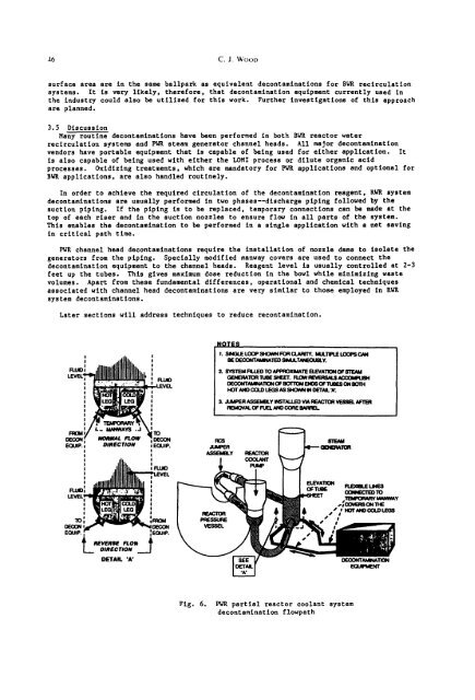
PWR channel head decontaminations require the installation of nozzle dams to isolate the<br />
generators from the piping. Specially modified manway covers are used to connect the<br />
decontamination equipment to the channel heads. Reagent level is usually controlled at 2-3<br />
feet up the tubes. This gives maximum dose reduction in the bowl while minimizing waste<br />
volumes. Apart from these fundamental differences, operational and chemical techniques<br />
associated with channel head decontaminations are very similar to those employed in RWR<br />
system decontaminations.<br />
Later sections will address techniques to reduce recontamlnetion.<br />
~ LEVEL<br />
FttMO<br />
DE(X~N r, ~mWAL FLOW :<br />
sou: : ms~c.oN : E(~,P<br />
: ! LEVEL<br />
! I I<br />
lo fq~)M<br />
E~.~. ,'2" :~,P.<br />
L_ ols~c.o..__j<br />
NOTE~<br />
,. S~,CE CCX~ SHOVM r-c~ cu~nY. ~CT~UEb.X~C~<br />
BE OECONTAMINATED SIM~TANEOUELY.<br />
2. SYSTEM FILLED TO APPI:IOXIMATE BLEVATION OF STEAM<br />
~d~IERATOR 1UBE SHEE'I'. FLOW FEVERSN.S .~OOOla~JSH<br />
DECONTAMNAllON OF BOTTOtl ENDS OF ~SES ON BOTH<br />
HOT AND COLID LEGS AS SHOWN IN DETAIL "A'.<br />
& JU~ ASSEMBLY I~STALLEO V~ REAGiOH ~.~ @ ll=M<br />
REkW~VAL OF FUEL ANO CORE 8NqflEL<br />
QF'IIIeE<br />
,#~<br />
DETAIL 'A' ~~__/TIGN<br />
Fig. 6. ~ partial reactor coolant system<br />
decontamination flowpath


