Installation and Operating Instruction
Installation and Operating Instruction
Installation and Operating Instruction

You also want an ePaper? Increase the reach of your titles
YUMPU automatically turns print PDFs into web optimized ePapers that Google loves.
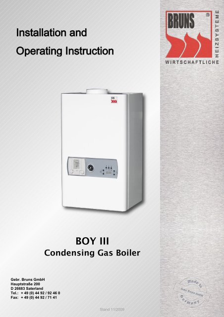
<strong>Installation</strong> <strong>and</strong><br />
<strong>Operating</strong> <strong>Instruction</strong><br />
Gebr. Bruns GmbH<br />
Hauptstraße 200<br />
D 26683 Saterl<strong>and</strong><br />
Tel.: + 49 (0) 44 92 / 92 46 0<br />
Fax: + 49 (0) 44 92 / 71 41<br />
BOY III<br />
Condensing Gas Boiler<br />
St<strong>and</strong> 11/2009
Table of contents<br />
1 Introduction 4<br />
1.1 Symbols used in this manual 4<br />
1.2 Liability 4<br />
1.3 Factory Warranty 4<br />
2 Product Description 5<br />
2.1 Product Description 5<br />
2.2 Intended use 5<br />
2.3 Equipment configuration BOY III Solo 6<br />
2.4 Equipment configuration BOY III Combi 7<br />
3 Regulations, Guidelines, Safety 8<br />
3.1 Regulations <strong>and</strong> Guidelines 8<br />
3.2 Safety Warning 9<br />
3.2.1 What to Do if You Smell Gas 9<br />
3.2.2 Risk of Poisoning 9<br />
3.2.3 Risk of Freezing 10<br />
3.2.4 Relief Valve 10<br />
3.2.5 Aspirator 10<br />
3.2.6 Pressure Compensating Tank for Drinking Water 11<br />
3.2.7 Pressure Compensating Tank for the Heating System 11<br />
3.2.8 Water Deficiency Safety Fuse 11<br />
3.2.9 High Temperature cut out 11<br />
3.2.10 Corrosion Protection 12<br />
3.2.11 <strong>Installation</strong> Location Requirements 12<br />
3.2.12 Minimum Safety Distances 12<br />
4 Mounting/<strong>Installation</strong> 13<br />
4.1 Shipment Contents 13<br />
4.2 Mounting the Unit 14<br />
4.2.1 General <strong>Instruction</strong>s for Connection the Heating Unit 15<br />
4.2.2 Connecting the Heating Unit (Supply <strong>and</strong> Return Lines) 15<br />
4.2.3 Connecting for Drinking Water (BOY III Combi) 16<br />
4.2.4 Connecting for Use with an External Reservoir 16<br />
4.2.5 General <strong>Instruction</strong>s for the Gas Connection 17<br />
4.2.6 Connecting the Gas Main 17<br />
4.2.7 General <strong>Instruction</strong>s for Connecting the Gas Flue 18<br />
4.2.8 Chimney Compatibility 18<br />
4.2.9 Heating Duct Requirements 18<br />
4.2.10 Maximum Length of Flue Ducts <strong>and</strong> Number of Directional Changes 18<br />
4.2.11 Reducing the Maximum Delivery Height 18<br />
4.2.12 Lighting Protection 18<br />
4.2.13 Connecting the Unit to the Chimney 19<br />
4.2.14 Installing the Emissions Connection to Central Roof Heating 21<br />
4.2.15 Connecting the Condensed Water Drain 21<br />
4.2.16 Neutralisation 21<br />
4.2.17 General <strong>Instruction</strong>s for the Electrical Connection 22<br />
4.2.18 Electrical Connection 22<br />
4.2.19 Pin Assignment on the Terminal Strip 23<br />
Gebr. Bruns GmbH is not responsible for typographical errors or technical inaccuracies <strong>and</strong> reserves the right to make adjustments.<br />
Gebr. Bruns GmbH • Hauptstraße 200 • 26683 Saterl<strong>and</strong> •Tel.: + 49 (0) 44 92 / 92 46-0 • Fax: + 49 (0) 44 92 / 71 41<br />
www.bruns-heiztechnik.de • info@bruns-heiztechnik.de
Table of contents<br />
5 Start up 24<br />
5.1 Filling <strong>and</strong> Ventilating the Heating System 24<br />
5.2 Ventilating the Unit 24<br />
5.3 Ventilating the Lower/St<strong>and</strong>ing Reservoir (optional) 25<br />
5.4 Start up 26<br />
5.4.1 Performance of the Unit Test Routine upon Start up 26<br />
5.5 (Pre) Setting the Boiler 26<br />
5.5.1 CO2 Boiler Settings 26<br />
5.5.2 Gas Throughput Table / Connection Pressure 27<br />
5.5.3 Changing Gas Types 27<br />
6 <strong>Operating</strong> the Controls 28<br />
6.1 Description of the Control Panel 28<br />
6.2 LED Display Symbols 28<br />
6.3 Controller Functions <strong>and</strong> <strong>Operating</strong> Status 29<br />
6.3.1 Start up 29<br />
6.3.2 St<strong>and</strong>by Mode 29<br />
6.3.3 Flame Detector 29<br />
6.3.4 Central Heating Mode 30<br />
6.3.4.1 <strong>Operating</strong> the Central Heater 30<br />
6.3.4.2 Anti-Cycling Central Heating 30<br />
6.3.5 Drinking Water Mode 30<br />
6.3.5.1 <strong>Operating</strong> the Drinking-Water Heater 30<br />
6.3.5.2 Anti-Cycling Drinking-Water Heater 31<br />
6.3.6 Changing the Set-point 31<br />
6.3.6.1 Changing the Set-point for Central Heating 31<br />
6.3.6.2 Changing the Set-point for the Drinking-Water Heater 31<br />
6.3.7 Summer Mode 32<br />
6.3.8 Chimney Sweep Mode 32<br />
6.3.9 Installer Mode 32<br />
6.3.10 Installer (+) Mode 33<br />
6.3.10.1 Installer (+) Parameter List 34<br />
7 Malfunctions <strong>and</strong> Errors 36<br />
7.1 Error Mode 36<br />
7.2 Error Code List 36<br />
7.2.1 Shutdown Codes 36<br />
7.2.2 Locking Codes 37<br />
7.3 Error history Mode 39<br />
7.4 Log Resistance Values for the Boiler <strong>and</strong> Reservoir Sensors 39<br />
8 Maintenance 40<br />
8.1 General <strong>Instruction</strong>s for Maintenance 40<br />
8.2 Cleaning the Condensed Water Siphon 40<br />
8.3 Cleaning the Combustion Chamber 40<br />
9 Technical Data 43<br />
9.1 Circuit Diagram 43<br />
9.2 Technical Data 44<br />
10 Declaration of Conformity 46<br />
Gebr. Bruns GmbH is not responsible for typographical errors or technical inaccuracies <strong>and</strong> reserves the right to make adjustments.<br />
Gebr. Bruns GmbH • Hauptstraße 200 • 26683 Saterl<strong>and</strong> •Tel.: + 49 (0) 44 92 / 92 46-0 • Fax: + 49 (0) 44 92 / 71 41<br />
www.bruns-heiztechnik.de • info@bruns-heiztechnik.de
Introduction<br />
1 Introduction<br />
Dear customer,<br />
We congratulate you on your decision to use the BOY III Condensing Gas Boiler. By<br />
purchasing the BOY III, you have secured the most current level of innovation in boiler<br />
technology.<br />
We will gladly answer any questions or provide any information you may need.<br />
We thank you for your trust <strong>and</strong> hope you enjoy you BOY III Condensing Gas Boiler.<br />
Gebr. BRUNS GmbH,<br />
Your partner for heating technology<br />
1.1 Symbols used in this manual<br />
Failure to follow instructions marked with this symbol risks life <strong>and</strong> limb; a defect<br />
in the unit is possible.<br />
This Symbol denotes important <strong>Instruction</strong>s <strong>and</strong> Information.<br />
This symbol marks tasks to be fulfilled.<br />
1.2 Liability<br />
Gebr. Bruns GmbH is not liable for damages caused by not observing this installation<br />
<strong>and</strong> operating instruction.<br />
1.3 Factory Warranty<br />
We provide a factory warranty for the owner in accordance with the current conditions<br />
<strong>and</strong> deadlines in the Gebr. Bruns GmbH’s general terms <strong>and</strong> conditions. The<br />
warranty does not cover damages caused by normal wear <strong>and</strong> tear, insufficient water<br />
quality, aggressive fumes or strong dust. Warranty work is performed exclusively by<br />
the factory. We can, therefore, only reimburse you for expenses incurred for repairs<br />
done during the warranty period if we have received a proper order <strong>and</strong> have<br />
deemed it to be covered by the warranty.<br />
- 4 -<br />
Gebr. Bruns GmbH is not responsible for typographical errors or technical inaccuracies <strong>and</strong> reserves the right to make adjustments.<br />
Gebr. Bruns GmbH • Hauptstraße 200 • 26683 Saterl<strong>and</strong> •Tel.: + 49 (0) 44 92 / 92 46-0 • Fax: + 49 (0) 44 92 / 71 41<br />
www.bruns-heiztechnik.de • info@bruns-heiztechnik.de
Product Description<br />
2 Product Description<br />
2.1 Product Description<br />
The BOY III is a compact, wall-hanging condensing gas boiler that weighs very little.<br />
The BOY III can be operated dependent or independent of compartment air. All of<br />
the basic parts are inside the powder-coated steel-plated casing. The stainless steel<br />
heat exchanger is designed for exhaust condensation operation <strong>and</strong> is very selfcleaning.<br />
With its 1:5 modulation ratio, the force draught fan supported burner, designed<br />
especially for gas boilers, is very efficient in its energy use <strong>and</strong> emissions.<br />
The connections can be placed from below the unit. An atmospheric or temperature<br />
sensor can be attached to the boiler controller. These sensors can, depending on<br />
how they are set up, regulate up to two mixing valve circuit.<br />
2.2 Intended use<br />
Fig. 1: Boy III<br />
The BOY III is a condensing gas boiler <strong>and</strong> is exclusively for use as a heating<br />
unit for heating systems.<br />
Any misuse is prohibited<br />
- 5 -<br />
Gebr. Bruns GmbH is not responsible for typographical errors or technical inaccuracies <strong>and</strong> reserves the right to make adjustments.<br />
Gebr. Bruns GmbH • Hauptstraße 200 • 26683 Saterl<strong>and</strong> •Tel.: + 49 (0) 44 92 / 92 46-0 • Fax: + 49 (0) 44 92 / 71 41<br />
www.bruns-heiztechnik.de • info@bruns-heiztechnik.de
Product Description<br />
2.3 Equipment configuration BOY III Solo<br />
Burner Unit<br />
Ionisation<br />
Force Draught Fan<br />
Relief Valve<br />
Flow Sensor<br />
Water Pressure Sensor<br />
Fig. 2: BOY III Solo<br />
- 6 -<br />
High Temperature<br />
Sensor<br />
Ignition Electrode<br />
Automatic Firing Device<br />
Gebr. Bruns GmbH is not responsible for typographical errors or technical inaccuracies <strong>and</strong> reserves the right to make adjustments.<br />
Gas Valve<br />
Return Sensor<br />
Circulation Pump<br />
Gebr. Bruns GmbH • Hauptstraße 200 • 26683 Saterl<strong>and</strong> •Tel.: + 49 (0) 44 92 / 92 46-0 • Fax: + 49 (0) 44 92 / 71 41<br />
www.bruns-heiztechnik.de • info@bruns-heiztechnik.de
Product Description<br />
2.4 Equipment configuration BOY III Combi<br />
Burner Unit High Temperature<br />
cut out<br />
Ionisation<br />
Force Draught Fan<br />
Plate Heat<br />
Exchanger<br />
Relief Valve<br />
Flow Sensor<br />
Water Pressure Sensor<br />
Fig. 3: BOY III Combi<br />
Warm Water Sensor Circulation Sensor<br />
- 7 -<br />
Ignition Electrode<br />
Automatic Firing Device<br />
Gebr. Bruns GmbH is not responsible for typographical errors or technical inaccuracies <strong>and</strong> reserves the right to make adjustments.<br />
Gas Valve<br />
Return Sensor<br />
Circulation Pump<br />
Gebr. Bruns GmbH • Hauptstraße 200 • 26683 Saterl<strong>and</strong> •Tel.: + 49 (0) 44 92 / 92 46-0 • Fax: + 49 (0) 44 92 / 71 41<br />
www.bruns-heiztechnik.de • info@bruns-heiztechnik.de
Regulations, Guidelines, Safety<br />
3 Regulations, Guidelines, Safety<br />
3.1 Regulations <strong>and</strong> Guidelines<br />
Regarding mounting, installation, <strong>and</strong> operation of the BOY III, the following laws, ordinances,<br />
regulations, norms <strong>and</strong> rules apply according to the current versions.<br />
In other countries, the respective national regulations apply.<br />
BImSchV Federal Emissions Protection Regulation<br />
DIN 18160 Emissions Systems – Design <strong>and</strong> Operation<br />
DIN 18380 Heating Systems <strong>and</strong> Central Water Heating Systems<br />
DIN 1988 Teil 1 – 8 Technical Regulations for Drinking Water <strong>Installation</strong><br />
DIN 4753 Water heater <strong>and</strong> Water heating Systems for Drinking Water<br />
<strong>and</strong> Domestic Use<br />
DIN EN 12828 Water heating System Design<br />
DIN EN 12831 Procedure for Calculating the Heating Load Norm<br />
DIN EN 13384 Procedure for Calculating Emissions Systems – Heat <strong>and</strong><br />
Supply<br />
DIN EN 267 Automatic Burner with Force Draught Fan for Liquid Fuels<br />
DVGW G 631 <strong>Installation</strong> of Commercial Gas Consuming Appliances<br />
DVGW G 634 <strong>Installation</strong> of Gas Units in Commercial Kitchens in Buildings<br />
DVGW G 670 Gas Fire Locations <strong>and</strong> Mechanical Ventilation Systems<br />
DVGW TRGI 86 Technical Regulations for Gas <strong>Installation</strong><br />
EnEG Energy Conservation Law<br />
EnEV Energy Conservation Regulation<br />
FeuVO Fire Regulations per State<br />
VDE Rules <strong>and</strong> Regulations for Electro-Technical, Electronics,<br />
<strong>and</strong> Information Technology<br />
VDI 2035 Prevention of Damages in Water Heating Systems – Accumulation<br />
of Stone in Drinking Water <strong>and</strong> Water Heating systems<br />
– Corrosive Water – Corrosive Emissions<br />
This list may not be complete!<br />
Before installing the condensing gas boiler BOY III, it is necessary to attain<br />
approval from the Gas Supply Ordinance Board <strong>and</strong> the District Chimney<br />
Sweep Foreman.<br />
- 8 -<br />
Gebr. Bruns GmbH is not responsible for typographical errors or technical inaccuracies <strong>and</strong> reserves the right to make adjustments.<br />
Gebr. Bruns GmbH • Hauptstraße 200 • 26683 Saterl<strong>and</strong> •Tel.: + 49 (0) 44 92 / 92 46-0 • Fax: + 49 (0) 44 92 / 71 41<br />
www.bruns-heiztechnik.de • info@bruns-heiztechnik.de
Regulations, Guidelines, Safety<br />
3.2 Safety Warning<br />
Attention: Electrical installation <strong>and</strong> initial operation may only be performed by<br />
a licensed professional! This also pertains to maintenance, cleaning, <strong>and</strong> repair.<br />
● Do not use if system is damaged.<br />
● Only original parts may be used.<br />
● Changes <strong>and</strong> repairs made on one’s own authority are not allowed, as<br />
such may result in damages to the unit or injury or death.<br />
● When operated in a compartment air-dependent area, ventilation (in<br />
<strong>and</strong> out) must not be obstructed. The intake of combustion air on the<br />
top of the BOY III must be kept free of obstructions.<br />
3.2.1 What to Do if You Smell Gas<br />
Avoid open fire, smoking, turning on lights, or unplugging anything in rooms<br />
that smell like gas. Under no circumstances should you use the telephone.<br />
Close the gas meter valve! Have your installation technician show you where<br />
the gas valve is <strong>and</strong> how to close it.<br />
Do not use doorbells or light switches in other rooms.<br />
If you smell gas, use a telephone in a neighbouring building or use a phone<br />
booth. Mobile phones should also be used outside of the building.<br />
Call the service department, even if you smell gas somewhere else.<br />
Do not forget to warn housemates <strong>and</strong> neighbours <strong>and</strong> vacate the premises.<br />
Secure the building against unauthorized entry.<br />
Even if you aren’t sure if it is a gas smell, you should contact your energy provider<br />
as a precaution.<br />
3.2.2 Risk of Poisoning<br />
Never use water from the heating system as drinking water! It is contaminated with<br />
deposits.<br />
- 9 -<br />
Gebr. Bruns GmbH is not responsible for typographical errors or technical inaccuracies <strong>and</strong> reserves the right to make adjustments.<br />
Gebr. Bruns GmbH • Hauptstraße 200 • 26683 Saterl<strong>and</strong> •Tel.: + 49 (0) 44 92 / 92 46-0 • Fax: + 49 (0) 44 92 / 71 41<br />
www.bruns-heiztechnik.de • info@bruns-heiztechnik.de
Regulations, Guidelines, Safety<br />
3.2.3 Risk of Freezing<br />
If the unit is at risk of freezing, it is necessary to be kept operational in conservation<br />
mode (at minimum) <strong>and</strong> all radiator valves should be kept open. If you cannot heat<br />
during freezing periods, turn off the system <strong>and</strong> empty the boiler, the warm water<br />
storage tank <strong>and</strong> the radiators. The boiler must be secured against accidental activation<br />
when empty.<br />
3.2.4 Relief Valve<br />
The condensing gas boiler comes with a 2.5 bar relief<br />
valve. The opening of the spring-loaded membranous<br />
relief valve must be in a frost free area <strong>and</strong> must be easily<br />
accessible. The blow off pipe on the relief valve must<br />
be implemented without the possibility of increasing<br />
pressure while responding to the relief valve. Leaking<br />
heater water should be safely siphoned off.<br />
Operational readiness of the relief valve should be<br />
checked from time to time.<br />
3.2.5 Aspirator<br />
To ventilate the boiler with water in it, the<br />
aspirator cap on the top of the unit must be<br />
open by turning it two rotations to the left.<br />
An additional automatic aspirator can be<br />
found under the pump casing. This may<br />
only be set by a licensed professional.<br />
- 10 -<br />
Fig. 4 Relief Valve<br />
Fig. 5 Manual Quick-Aspirator<br />
Fig. 6 Automatic Quick-Aspirator<br />
Gebr. Bruns GmbH is not responsible for typographical errors or technical inaccuracies <strong>and</strong> reserves the right to make adjustments.<br />
Gebr. Bruns GmbH • Hauptstraße 200 • 26683 Saterl<strong>and</strong> •Tel.: + 49 (0) 44 92 / 92 46-0 • Fax: + 49 (0) 44 92 / 71 41<br />
www.bruns-heiztechnik.de • info@bruns-heiztechnik.de
Regulations, Guidelines, Safety<br />
3.2.6 Pressure Compensating Tank for Drinking Water<br />
In combination with a drinking water reservoir,<br />
a membranous pressure compensating<br />
tank that has been approved for filtering<br />
domestic-use water to drinking water is required.<br />
This tank should have ample space<br />
<strong>and</strong> must be installed externally in accordance<br />
with TRWI regulations. The size of the<br />
tank is dependent upon the volume of domestic-use<br />
water reservoir.<br />
3.2.7 Pressure Compensating Tank for the Heating System<br />
On the heater side, a membranous pressure<br />
compensating tank is required. This<br />
tank should have ample space <strong>and</strong> is to be<br />
installed externally. The size of the tank is<br />
dependent upon the volume of heating system’s<br />
water reservoir as well as the temperature<br />
requirements.<br />
Fig. 7 Pressure Compensating Tank for<br />
Drinking Water<br />
Fig. 8 Pressure Compensating Tank for the<br />
Heating System<br />
Setting the primary pressure of the pressure compensating tanks to the<br />
respective static levels is required <strong>and</strong> may only be performed by a licensed<br />
professional.<br />
3.2.8 Water Deficiency Safety Fuse<br />
A minimum circulation rate of 360 l/h is required. Furthermore, a water pressure<br />
sensor makes sure that at a system pressure of 0.6 bar, the system automatically<br />
shuts down. As soon as the water pressure returns to above 0.6 bar, the unit<br />
will turn itself back on automatically.<br />
3.2.9 High Temperature cut out<br />
The unit has a temperatur cut out with a melting fuse. This safety guard is only a protection<br />
against burning out of the heat exchanger. If this fuse is blown out, the complete<br />
heat exchanger has to be changed, because the baffle plate within, is most<br />
probably damaged.<br />
- 11 -<br />
Gebr. Bruns GmbH is not responsible for typographical errors or technical inaccuracies <strong>and</strong> reserves the right to make adjustments.<br />
Gebr. Bruns GmbH • Hauptstraße 200 • 26683 Saterl<strong>and</strong> •Tel.: + 49 (0) 44 92 / 92 46-0 • Fax: + 49 (0) 44 92 / 71 41<br />
www.bruns-heiztechnik.de • info@bruns-heiztechnik.de
Regulations, Guidelines, Safety<br />
3.2.10 Corrosion Protection<br />
The combustion air must be free of all corrosive elements – especially those containing<br />
fluoride <strong>and</strong> chloride such as those found in solvents <strong>and</strong> cleaning solutions, propellants<br />
an so on.<br />
When connecting a water heater to a floor heater with non-airtight plastic tubing (in<br />
accordance with DIN 4726), a heat exchanger must be used to separate the systems.<br />
To avoid corrosion damage in the heating system, heating water that fulfils the drinking<br />
water quality requirements in VDI guideline 2035 (Prevention of Damages in Water<br />
Heating Systems) must be used. Chemical additives are not to be used.<br />
3.2.11 <strong>Installation</strong> Location Requirements<br />
● When operated in a compartment air-dependent area, the unit must be housed<br />
in a room with clean combustion air. Under no circumstances should foreign<br />
substances such as pollen get inside the unit via the intake duct!<br />
● The installation location must be dry <strong>and</strong> frost free (0°C to 45°C).<br />
● The boiler room must be protected against small animals, vermin <strong>and</strong> pests.<br />
● When operated in a compartment air-dependent area, the boiler room must<br />
have a functioning ventilation <strong>and</strong> emission system.<br />
● Flammable material or liquids must not be stored or used near the boiler. Follow<br />
fire prevention guidelines!<br />
3.2.12 Minimum Safety Distances<br />
For optimal installation of the boiler,<br />
we recommend a lateral distance of<br />
200 mm from the walls <strong>and</strong> a vertical<br />
distance of 500 mm from the ceiling.<br />
Reducing these distances is allowed<br />
according to legal guidelines.<br />
The lateral distances should not fall<br />
below 100 mm.<br />
- 12 -<br />
200<br />
4 0 0<br />
Fig. 9 Minimum Safety Distances (mm)<br />
Gebr. Bruns GmbH is not responsible for typographical errors or technical inaccuracies <strong>and</strong> reserves the right to make adjustments.<br />
Gebr. Bruns GmbH • Hauptstraße 200 • 26683 Saterl<strong>and</strong> •Tel.: + 49 (0) 44 92 / 92 46-0 • Fax: + 49 (0) 44 92 / 71 41<br />
www.bruns-heiztechnik.de • info@bruns-heiztechnik.de
Mounting / <strong>Installation</strong><br />
4 Mounting/<strong>Installation</strong><br />
4.1 Shipment Contents<br />
Please make sure the shipment is complete <strong>and</strong> undamaged before you begin<br />
with the installation!<br />
The delivery comes in a cardboard box.<br />
1<br />
Fig. 10 Shipment Contents<br />
Pos. Anzahl Bezeichnung<br />
1 1 Condensing Gas Boiler BOY III<br />
2 1 Atmospheric or Temperature Sensor (Optional)<br />
3 1 Pressure Gauge<br />
4 1 Control Keypad with Illuminated Display<br />
5 1 Wall Mounting Track<br />
6 2 Mounting Screws incl. Washers<br />
7 2 Plastic Expansion Studs<br />
8 1 <strong>Installation</strong> <strong>and</strong> Operation Manual<br />
- 13 -<br />
Gebr. Bruns GmbH is not responsible for typographical errors or technical inaccuracies <strong>and</strong> reserves the right to make adjustments.<br />
Gebr. Bruns GmbH • Hauptstraße 200 • 26683 Saterl<strong>and</strong> •Tel.: + 49 (0) 44 92 / 92 46-0 • Fax: + 49 (0) 44 92 / 71 41<br />
www.bruns-heiztechnik.de • info@bruns-heiztechnik.de<br />
2<br />
3<br />
4<br />
5<br />
6<br />
7
Mounting / <strong>Installation</strong><br />
4.2 Mounting the Unit<br />
The unit comes with a track for easy wall mounting. Before mounting the<br />
unit, please read the following requirements:<br />
• The wall must be stable enough to hold the unit.<br />
• An outlet with contact protection for electricity <strong>and</strong> a water drainage<br />
connection should both be in close proximity.<br />
• Make sure to check the wall for electrical wiring <strong>and</strong> water <strong>and</strong> gas pipes<br />
before drilling as they may get damaged.<br />
• To protect the boiler from contamination, place protective covers over<br />
all connections. Please remove these only at the appropriate installation<br />
stage.<br />
Next, measure the wall intended as the location<br />
of the unit. Follow the measurements of<br />
the unit <strong>and</strong> the minimum safety distances. If<br />
the unit is to be attached to an existing chimney,<br />
use the emissions connection, including<br />
the elbow as the point of reference.<br />
Mark the drilling positions for the mounting<br />
track <strong>and</strong> drill using an 8 mm bit.<br />
Place the plastic expansion studs in the wall<br />
<strong>and</strong> fasten the track to the wall with the<br />
screws. Use a level to make sure the track is<br />
straight <strong>and</strong> then screw it tightly to the wall.<br />
Hang the unit to the mounted track <strong>and</strong> make<br />
sure it is mounted firmly.<br />
Use the setting screws at the bottom of the<br />
back of the boiler to align it parallel to the wall.<br />
Check one more time with the level to make<br />
sure the boiler is straight.<br />
- 14 -<br />
3 2 0<br />
Fig. 11 Wall Track<br />
8 5<br />
Fig. 12 Wall Mount (mm)<br />
Gebr. Bruns GmbH is not responsible for typographical errors or technical inaccuracies <strong>and</strong> reserves the right to make adjustments.<br />
Gebr. Bruns GmbH • Hauptstraße 200 • 26683 Saterl<strong>and</strong> •Tel.: + 49 (0) 44 92 / 92 46-0 • Fax: + 49 (0) 44 92 / 71 41<br />
www.bruns-heiztechnik.de • info@bruns-heiztechnik.de
Mounting / <strong>Installation</strong><br />
4.2.1 General <strong>Instruction</strong>s for Connection the Heating Unit<br />
● Before connecting the boiler to the heating system, the heating system<br />
must be rinsed at a minimum of 3 times the flow capacity. The drinking<br />
water pipes must be rinsed at a minimum of 20 times its flow capacity.<br />
● In older systems, a filter must be placed in the heating circuit in the return<br />
supply line before the opening to the boiler.<br />
● Use only untreated tap water to fill <strong>and</strong> refill the heating system.<br />
● The pH value must be between 6 <strong>and</strong> 9.<br />
● Do not add any chemicals to the heating system’s water (e.g. anti-freeze,<br />
water softener, solutions to raise or lower the pH value, chemical<br />
additives <strong>and</strong>/or inhibitors). These can damage the boiler.<br />
● When using plastic pipes (e.g. in floor heaters), the pipes must be air<br />
<strong>and</strong> diffusion tight in accordance with DIN 4726/ 4729.<br />
● If the system’s plastic pipes are not in accordance with the norms, we<br />
recommend separating the boiler circulation system from the heating<br />
system with a (plate) heat exchanger or a filter mounted hydraulically<br />
in front of the boiler connection.<br />
● The temperature of the heating ducts <strong>and</strong> radiators can go up to 95 °C.<br />
4.2.2 Connecting the Heating Unit (Supply <strong>and</strong> Return Lines)<br />
There are flue cut-off devices that must be<br />
mounted directly under the boiler. These<br />
should have the respective diameters of the<br />
connections to which they belong. Permanently<br />
soldered or welded connections are not<br />
allowed.<br />
A separate line for filling <strong>and</strong> draining must be<br />
installed <strong>and</strong> easily accessible. If the line for<br />
filling <strong>and</strong> draining is not at the lowest point of<br />
the unit, an additional device must be installed<br />
so the system can be completely drained.<br />
Older systems <strong>and</strong> floor heating systems require<br />
a filter in the return line directly on the<br />
boiler.<br />
S R A K<br />
V L S V<br />
R L<br />
G<br />
Fig. 13 Connections: BOY III Solo<br />
S R A K<br />
V L W W S V<br />
K W R L<br />
G<br />
Fig. 14 Connections: BOY III Combi<br />
SR Siphon-Cleaning VL Supply WW Warm Water SV Drainage Safety Valve<br />
AK Condensation Drainage RL Return Flow KW Cold Water G Gas Connection<br />
- 15 -<br />
Gebr. Bruns GmbH is not responsible for typographical errors or technical inaccuracies <strong>and</strong> reserves the right to make adjustments.<br />
Gebr. Bruns GmbH • Hauptstraße 200 • 26683 Saterl<strong>and</strong> •Tel.: + 49 (0) 44 92 / 92 46-0 • Fax: + 49 (0) 44 92 / 71 41<br />
www.bruns-heiztechnik.de • info@bruns-heiztechnik.de
Mounting / <strong>Installation</strong><br />
4.2.3 Connecting for Drinking Water (BOY III Combi)<br />
The drinking water access must be<br />
equipped in accordance with DIN 1988<br />
<strong>and</strong> DIN 4753 to avoid dirt or germs that<br />
can contaminate the cold water network.<br />
The necessary parts <strong>and</strong> their configuration<br />
are shown in the diagram to the right.<br />
T W<br />
4.2.4 Connecting for Use with an External Reservoir<br />
1 2 3 4 5 6<br />
1 . C u t - o f f v a l v e<br />
2 . F i l t e r<br />
3 . P r e s s u r e r e g u l a t o r<br />
4 . C h e c k v a l v e<br />
5 . N o n e - r e t u r n e v a l v e<br />
6 . M a n o m e t e r c o n n e c t i o n<br />
T W . M a i n s d r i n k i n g w a t e r<br />
Fig. 15 Connection Schematic:<br />
Drinking Water Access<br />
If the unit is connected to an external reservoir, an expansion tank <strong>and</strong> a 10 bar relief<br />
valve must be installed to protect the heating system. The BOY III Solo requires an<br />
additional three-way redirecting valve installed in the return flow line directly on the<br />
boiler.<br />
Fig. 16 Three-way Redirecting Valve<br />
The connections on the three-way redirection<br />
valve are as follows:<br />
AB = Return Flow Line BOY III<br />
A = Reservoir Connection<br />
B = Heating Circuit Connection<br />
- 16 -<br />
These connections should never, under<br />
any circumstances, be interchanged!<br />
The three-way redirecting valve is<br />
already integrated in to the BOY III.<br />
Gebr. Bruns GmbH is not responsible for typographical errors or technical inaccuracies <strong>and</strong> reserves the right to make adjustments.<br />
Gebr. Bruns GmbH • Hauptstraße 200 • 26683 Saterl<strong>and</strong> •Tel.: + 49 (0) 44 92 / 92 46-0 • Fax: + 49 (0) 44 92 / 71 41<br />
www.bruns-heiztechnik.de • info@bruns-heiztechnik.de<br />
1
Mounting / <strong>Installation</strong><br />
4.2.5 General <strong>Instruction</strong>s for the Gas Connection<br />
• The gas connection must be connected in accordance with the current<br />
regulations. <strong>Installation</strong> may only be performed by a licensed professional!<br />
• Make sure there is no open fire, flammable materials or the like in close<br />
proximity to the installation location. LIFE THREATENING DANGER!<br />
• Before installation, check to make sure the gas meter has adequate<br />
capacity. Take the usage of all household appliances into account.<br />
Let your energy provider know if your line does not have a high<br />
enough capacity.<br />
• Make sure the gas lines are clean. Clean the gas lines with high pressure<br />
or by knocking them clean before installation.<br />
• An approved shut-off valve with a fire protective faucet must be installed<br />
in front of the boiler.<br />
• Preferably, you can also install a gas filter to keep the gas control<br />
valve from getting dirty.<br />
4.2.6 Connecting the Gas Main<br />
Please follow these instructions during installation:<br />
• The main gas spigot must be shut off before the work begins. If the<br />
connection is older, make sure the spigot still closes to avoid uncontrolled<br />
gas leaking out.<br />
• Secure the line against accidental start up while you are working on<br />
the lines.<br />
• Make sure the fire protective faucet is mounted properly.<br />
• Before start up, make sure the entire gas line is sealed, especially at<br />
connection points. The gas faucet <strong>and</strong> the gas line may not exceed a<br />
maximum pressure of 150 mbar.<br />
• Ventilate the gas line after attaching to avoid malfunctions!<br />
• Ventilate the room well after installation to disperse any gas that may<br />
have escaped.<br />
- 17 -<br />
Gebr. Bruns GmbH is not responsible for typographical errors or technical inaccuracies <strong>and</strong> reserves the right to make adjustments.<br />
Gebr. Bruns GmbH • Hauptstraße 200 • 26683 Saterl<strong>and</strong> •Tel.: + 49 (0) 44 92 / 92 46-0 • Fax: + 49 (0) 44 92 / 71 41<br />
www.bruns-heiztechnik.de • info@bruns-heiztechnik.de
Mounting / <strong>Installation</strong><br />
4.2.7 General <strong>Instruction</strong>s for Connecting the Gas Flue<br />
Discuss regional guidelines for gas flue lines, cleaning openings <strong>and</strong> similar<br />
with the appropriate chimney sweep.<br />
4.2.8 Chimney Compatibility<br />
Heavily used <strong>and</strong> dirty chimneys are unsuitable for conducting combustion air (air<br />
supply through the chimney) <strong>and</strong> must be cleaned by a chimney sweep before use.<br />
If there are structural damages, such as brittle chimneys, soot build-up or the like, the<br />
chimney should be checked by a chimney sweep foreman to determine its stability. If<br />
cleaning the chimney isn’t possible, the unit can also be run through a concentric<br />
emissions pipe without being dependent upon compartment air. A compartment airdependent<br />
operating method is a possible alternative.<br />
Hooking up more than one or different types of boilers to one chimney should be approved<br />
by a chimney sweep foreman.<br />
4.2.9 Heating Duct Requirements<br />
Emission lines within buildings must be housed within their own ventilated ducts.<br />
The ducts must be made of non-flammable, form-holding materials. The duct’s fire<br />
resistance duration must be 90 minutes, in lower buildings, 30 minutes.<br />
4.2.10 Maximum Length of Flue Ducts <strong>and</strong> Number of Directional Changes<br />
Maximum length of<br />
Flue Duct<br />
Maximum Number of<br />
Directional Changes<br />
4.2.11 Reducing the Maximum Delivery Height<br />
Compartment air-dependent /Compartment air-independent<br />
Duct Layout Central Roof Heating<br />
21 m 4 m<br />
2 4<br />
When lengthening the connection lines by 1 m, the headroom of the emission lines is<br />
lowered by 1.5 m. Since the central roof heating system is limited to a total of 4.0 m,<br />
up to 4 directional changes can be installed. At an angle of 45°, the headroom is<br />
lowered by 0.5 m, at a 90° angle, by 1 m.<br />
4.2.12 Lighting Protection<br />
The chimney head cover must be into an existing lightning protection system <strong>and</strong> into<br />
a potential equalisation on the house. This should only be done by a licensed professional.<br />
- 18 -<br />
Gebr. Bruns GmbH is not responsible for typographical errors or technical inaccuracies <strong>and</strong> reserves the right to make adjustments.<br />
Gebr. Bruns GmbH • Hauptstraße 200 • 26683 Saterl<strong>and</strong> •Tel.: + 49 (0) 44 92 / 92 46-0 • Fax: + 49 (0) 44 92 / 71 41<br />
www.bruns-heiztechnik.de • info@bruns-heiztechnik.de
Mounting / <strong>Installation</strong><br />
4.2.13 Connecting the Unit to the Chimney<br />
Calculate the height of the opening for<br />
the emission pipe. Make sure to take<br />
headroom for the test connection <strong>and</strong> the<br />
revision T-piece (T-fitting) into account.<br />
m a x . 1 6 0 m m<br />
Ø 1 0 m m<br />
Fig. 18 Cross Section of the Duct<br />
Position the support bar according to the<br />
diagram to the right. The support bar<br />
must be level.<br />
- 19 -<br />
2 1 0 m m<br />
Fig. 17 BOY III with Emission Connection<br />
The opening for mounting the support bar<br />
should be made according to the diagram.<br />
Make sure the opening is no larger<br />
than160 mm x 160 mm; otherwise<br />
the cover will not be large enough.<br />
Drill the hole for the support bar with a 10<br />
mm bit. The support bar must be level.<br />
Fig. 19 Installing the Support Bar<br />
Gebr. Bruns GmbH is not responsible for typographical errors or technical inaccuracies <strong>and</strong> reserves the right to make adjustments.<br />
Gebr. Bruns GmbH • Hauptstraße 200 • 26683 Saterl<strong>and</strong> •Tel.: + 49 (0) 44 92 / 92 46-0 • Fax: + 49 (0) 44 92 / 71 41<br />
www.bruns-heiztechnik.de • info@bruns-heiztechnik.de
Mounting / <strong>Installation</strong><br />
Fig. 20 Insert the Emission Pipe into the Duct<br />
Mount the emission pipe between the unit<br />
<strong>and</strong> the support bar. The emission line to<br />
the unit must be placed at a slight downward<br />
slope, so condensation can flow<br />
back unhindered.<br />
Insert the pipe into the duct with a rope<br />
from above. The rope should stay taught<br />
at all times. Spacers should be placed<br />
every two meters after the collars.<br />
Place the support arc into the support<br />
bar.<br />
Fig. 21 Emission Connection - BOY III<br />
Follow the installation instructions for the respective emissions system!<br />
- 20 -<br />
Gebr. Bruns GmbH is not responsible for typographical errors or technical inaccuracies <strong>and</strong> reserves the right to make adjustments.<br />
Gebr. Bruns GmbH • Hauptstraße 200 • 26683 Saterl<strong>and</strong> •Tel.: + 49 (0) 44 92 / 92 46-0 • Fax: + 49 (0) 44 92 / 71 41<br />
www.bruns-heiztechnik.de • info@bruns-heiztechnik.de
Mounting / <strong>Installation</strong><br />
4.2.14 Installing the Emissions Connection to Central Roof Heating<br />
Measure the point where the emission<br />
pipe opening will be based on the position<br />
of the unit. Install the special feed<br />
through socket as appropriate for the<br />
space provided. Lead the emission pipe<br />
through the socket <strong>and</strong> connect it to the<br />
unit. Use the sleeves specially designed<br />
for the opening of the roofing paper in order<br />
to insure it is airtight. The emission<br />
line must be level.<br />
Fig. 22 Emissions Connection to Central<br />
Roof Heating<br />
Follow the installation instructions for the respective emissions system!<br />
4.2.15 Connecting the Condensed Water Drain<br />
Lay plastic piping (min. Ø 32 mm or larger that leads to the drain) app. 2 cm under<br />
the condensed water drain connection. Do not place a permanent connection on the<br />
siphon in the boiler as this hinders maintenance.<br />
4.2.16 Neutralisation<br />
• Fill the boiler siphon to avoid flue gases from escaping into the room.<br />
• The condensed water drain must not be sealed.<br />
• The emission pipe should have a minimum slope of 3 cm per meter<br />
<strong>and</strong> a maximum horizontal length of 5 meters.<br />
• Disposing of condensed water via rain gutters is not permitted.<br />
• Condensed water lines must be installed according to regulation.<br />
ATV Bulletin M 251 regulations <strong>and</strong> state provisions apply! A pH balancing system<br />
can be installed retroactively for the Bruns wall boiler. A neutralization system is required<br />
for boiler capacities exceeding 25 kW. Regional regulations for running condensed<br />
water into the canalisation system are a deciding factor. Neutralisation granulates<br />
must be checked yearly by the operator <strong>and</strong> if necessary, renewed.<br />
- 21 -<br />
Gebr. Bruns GmbH is not responsible for typographical errors or technical inaccuracies <strong>and</strong> reserves the right to make adjustments.<br />
Gebr. Bruns GmbH • Hauptstraße 200 • 26683 Saterl<strong>and</strong> •Tel.: + 49 (0) 44 92 / 92 46-0 • Fax: + 49 (0) 44 92 / 71 41<br />
www.bruns-heiztechnik.de • info@bruns-heiztechnik.de
Mounting / <strong>Installation</strong><br />
4.2.17 General <strong>Instruction</strong>s for the Electrical Connection<br />
• This should only be performed by a licensed professional!<br />
• Make sure the unit is disconnected from electricity before beginning!<br />
Life threatening danger!<br />
• In Germany, the VDE <strong>and</strong> local regulations must be followed when installing.<br />
• The condensing gas boiler must be connected to an emergency shut<br />
down switch.<br />
• All components must follow VDE regulations.<br />
• Attention! Life threatening danger! Connection to the main power supply<br />
(230V) should not be made until all remaining control components<br />
have been fully wired!<br />
4.2.18 Electrical Connection<br />
Remove the front cover from unit. To do<br />
this, remove the two screws at the bottom<br />
on the front of the unit. Hold the bottom<br />
of the cover <strong>and</strong> pull toward you.<br />
The front cover can then be pulled up<br />
<strong>and</strong> out.<br />
Remove the screws, 2 on top <strong>and</strong> 2 on<br />
the bottom of the terminal strip cover <strong>and</strong><br />
slide the cover out.<br />
- 22 -<br />
Remove the cover from the built-in slot in<br />
the controller.<br />
Screws<br />
Screws<br />
Gebr. Bruns GmbH is not responsible for typographical errors or technical inaccuracies <strong>and</strong> reserves the right to make adjustments.<br />
Gebr. Bruns GmbH • Hauptstraße 200 • 26683 Saterl<strong>and</strong> •Tel.: + 49 (0) 44 92 / 92 46-0 • Fax: + 49 (0) 44 92 / 71 41<br />
www.bruns-heiztechnik.de • info@bruns-heiztechnik.de<br />
1<br />
2
Mounting / <strong>Installation</strong><br />
1<br />
Screw<br />
Screw<br />
2<br />
You can lead additionally required cables<br />
into the unit through the cable opening on<br />
the bottom of the unit.<br />
Lay the cables as follows:<br />
• Lay current-carrying wires <strong>and</strong><br />
sensor leads separately. Use the<br />
lower clamp for the 230 V wire <strong>and</strong><br />
the upper clamp for the sensor<br />
lead <strong>and</strong> the bus line.<br />
• The clamps serve as stress relief.<br />
Make sure that the cables are long<br />
enough to be mounted without placing<br />
strain on them.<br />
4.2.19 Pin Assignment on the Terminal Strip<br />
Remove the two screws on the left of the<br />
operation panel. To open the panel, lift<br />
up lightly on the left side. You can then<br />
clap it open it to the right.<br />
Sensor Lead<br />
230 V Wires<br />
Make sure the electricity is disconnected before you begin!<br />
BOY III Combi comes with an integrated <strong>and</strong> preinstalled three-way valve<br />
- 23 -<br />
o r g o r w ew eo r w eg b l g r / gG e<br />
B W A F B U S 3 - W e Ng e t z<br />
V e n t i l<br />
N<br />
N<br />
B W<br />
= D H W S e n s o r<br />
A F<br />
= O u t d o o r T e m p . S e n<br />
B U S<br />
= H e a t i n g C o n t r o l l e r<br />
3 - W e g = e 3v -e W n t a i l y - V a l v e<br />
N e t z<br />
= G r i d c o n n e c t i o n ~ 2<br />
Gebr. Bruns GmbH is not responsible for typographical errors or technical inaccuracies <strong>and</strong> reserves the right to make adjustments.<br />
Gebr. Bruns GmbH • Hauptstraße 200 • 26683 Saterl<strong>and</strong> •Tel.: + 49 (0) 44 92 / 92 46-0 • Fax: + 49 (0) 44 92 / 71 41<br />
www.bruns-heiztechnik.de • info@bruns-heiztechnik.de<br />
L
Mounting / <strong>Installation</strong><br />
5 Start up<br />
5.1 Filling <strong>and</strong> Ventilating the Heating System<br />
The condensing gas boiler is not yet ready for operation!<br />
Fill the heating system to a maximum water pressure of1.5 bar!<br />
Ventilate the entire heating system via the installed ventilation valves on the<br />
radiators, floor heaters <strong>and</strong> so on. Keep the pressure at 1.5 bar while ventilating.<br />
5.2 Ventilating the Unit<br />
The gas line must be connected prior to<br />
ventilating the unit!<br />
Open the quick-aspirator on the pump<br />
app. two rotations. Wait until the air is<br />
gone from the quick-aspirator. Leave the<br />
aspirator open!<br />
- 24 -<br />
Activate the electrical supply by turning<br />
on the heater’s emergency switch. The<br />
unit’s circulating pump will then start up.<br />
Let the unit run with the gas main closed!<br />
Do not open the gas main! The unit will<br />
display an error code while the gas main<br />
is closed. Do not dejam!<br />
Open the manual aspirator on the top of<br />
the unit. Close this one as soon <strong>and</strong> the<br />
air is gone <strong>and</strong> water comes out.<br />
Gebr. Bruns GmbH is not responsible for typographical errors or technical inaccuracies <strong>and</strong> reserves the right to make adjustments.<br />
Gebr. Bruns GmbH • Hauptstraße 200 • 26683 Saterl<strong>and</strong> •Tel.: + 49 (0) 44 92 / 92 46-0 • Fax: + 49 (0) 44 92 / 71 41<br />
www.bruns-heiztechnik.de • info@bruns-heiztechnik.de
Mounting / <strong>Installation</strong><br />
5.3 Ventilating the Lower/St<strong>and</strong>ing Reservoir (optional)<br />
To ventilate the heat exchanger’s heating<br />
coil in the lower/st<strong>and</strong>ing reservoir, you<br />
must operate the three-way valve manually.<br />
To do this, remove the safety splint<br />
from the three-way valve ...<br />
Press the valve pin into the valve with a<br />
pair of pliers. The valve is now set to<br />
drinking water mode. The air in the drinking<br />
water heating coil can thus dispel<br />
from the unit via the aspirator.<br />
Re-establish the gas supply by opening<br />
the gas main.<br />
- 25 -<br />
<strong>and</strong> pull the motor off the valve.<br />
After successfully ventilating the unit, replace<br />
the motor onto the valve.<br />
Dejam the condensing gas boiler by holding<br />
down the III button.<br />
Gebr. Bruns GmbH is not responsible for typographical errors or technical inaccuracies <strong>and</strong> reserves the right to make adjustments.<br />
Gebr. Bruns GmbH • Hauptstraße 200 • 26683 Saterl<strong>and</strong> •Tel.: + 49 (0) 44 92 / 92 46-0 • Fax: + 49 (0) 44 92 / 71 41<br />
www.bruns-heiztechnik.de • info@bruns-heiztechnik.de
Mounting / <strong>Installation</strong><br />
5.4 Start up<br />
After successfully ventilating <strong>and</strong> dejamming the unit, it will start in drinking water<br />
mode (if available); otherwise it will start in hot water mode. To start in hot water<br />
mode or in drinking water mode, the unit requires a certain level of heat. This can be<br />
done by opening the thermostats on the radiators. If an error occurs during the start<br />
up phase, it will be shown on the display (see error code list).<br />
5.4.1 Performance of the Unit Test Routine upon Start up<br />
After turning on the unit, a manual reset of every 12/24 hours, the control unit will<br />
perform a start up test routine. The 12/24 hour reset is dependent upon whether or<br />
not the heating dem<strong>and</strong>s require it.<br />
No heating dem<strong>and</strong>s: The control unit will reset every 12 hours<br />
Heating dem<strong>and</strong>s: The control unit will reset every 24 hours<br />
During the start up test routine, the three-way valve, if there is one, is switched to<br />
drinking water heating mode <strong>and</strong> directly after back to central heating mode, regardless<br />
of the previous position of the valve. This way, one complete pass is made by<br />
the valve, which keeps the valve from seizing. The circulation pump is also turned on<br />
during the test routine.<br />
5.5 (Pre) Setting the Boiler<br />
5.5.1 CO2 Boiler Settings<br />
The unit must be in chimney sweep<br />
mode (Ch. 6.3.8) when setting the CO2-<br />
levels.<br />
The amount of CO2 in the unit can be set<br />
with the adjusting screw on the gas<br />
valve.<br />
With liquid gas, the starting load must be<br />
change from 50% up to 60%.<br />
The CO2 – content must lie between the following levels, regardless of load:<br />
Gas Type CO2-Wert<br />
Natural Gas 8,5 – 9,0 %<br />
Liquid Gas 10 – 10,5 %<br />
- 26 -<br />
Gebr. Bruns GmbH is not responsible for typographical errors or technical inaccuracies <strong>and</strong> reserves the right to make adjustments.<br />
Gebr. Bruns GmbH • Hauptstraße 200 • 26683 Saterl<strong>and</strong> •Tel.: + 49 (0) 44 92 / 92 46-0 • Fax: + 49 (0) 44 92 / 71 41<br />
www.bruns-heiztechnik.de • info@bruns-heiztechnik.de
Mounting / <strong>Installation</strong><br />
5.5.2 Gas Throughput Table / Connection Pressure<br />
Gas Type Load Area<br />
Gas Flow rate<br />
(l/min) Connection<br />
Pressure<br />
Min. Max.<br />
LL(L)-Gas 5,1 – 22,8 kW 11,6 50,1 20 mbar<br />
E(H)-Gas 5,1 – 22,8 kW 10,0 43,3 20 mbar<br />
Liquid Gas 5,1 – 22,8 kW 8,0 34,6 50 mbar<br />
Heating value: Natural Gas LL(L) = 8,83kWh/m³; Natural Gas E(H) = 10,22 kWh/m³; Liquid Gas = 12,78 kWh/m³<br />
The above gas type values may vary regionally. Please ask your energy provider for<br />
the heating values as necessary.<br />
5.5.3 Changing Gas Types<br />
Changing gas types does not require any adaptations to the unit. Simply adjust the<br />
CO2 Level (Ch. 5.5.1) to the respective gas type.<br />
- 27 -<br />
Gebr. Bruns GmbH is not responsible for typographical errors or technical inaccuracies <strong>and</strong> reserves the right to make adjustments.<br />
Gebr. Bruns GmbH • Hauptstraße 200 • 26683 Saterl<strong>and</strong> •Tel.: + 49 (0) 44 92 / 92 46-0 • Fax: + 49 (0) 44 92 / 71 41<br />
www.bruns-heiztechnik.de • info@bruns-heiztechnik.de
<strong>Operating</strong> the Controls<br />
6 <strong>Operating</strong> the Controls<br />
6.1 Description of the Control Panel<br />
T a s t4 e<br />
T a s t 5 e<br />
L E D 1 L E D 2 L E D 3<br />
T a s t e1 2 3<br />
I II III<br />
8.8.8.<br />
S e g m e Cn t B D<br />
T a s t 6e<br />
L E D 4 L E D 5<br />
P u n k t C B<br />
D<br />
6.2 LED Display Symbols<br />
T a s t 7e<br />
Taste 1<br />
Function Description<br />
Switch to summer mode/ Chimney sweep<br />
mode<br />
Taste 2 <strong>Installation</strong> Mode / <strong>Installation</strong> (+) Mode<br />
Taste 3 Dejamming/ End Mode/ Error Log<br />
Taste 4 Positive Set-point changes heating water<br />
Taste 5 Negative Set-point changes heating water<br />
Taste 6 Positive Set-point Changes Drinking Water<br />
Taste 7 Negative Set-point Changes Drinking Water<br />
LED 1 Summer Mode on / off<br />
LED 2 Display Installer / Installer (+) Mode<br />
LED 3 Display Error<br />
LED 4<br />
LED 5<br />
Segment<br />
B / C / D<br />
Heating Water Requirements on / off<br />
Anti-Cycling on / off<br />
Drinking Water Heating Dem<strong>and</strong>s on / off<br />
Anti-Cycling on / off<br />
Display Temperature, Parameters, Error<br />
Codes<br />
Punkt D Display Flame detector (Flame on / off)<br />
Symbol Meaning Symbol’s Reference Name<br />
Central Heating Central Heating-Symbol<br />
Drinking Water<br />
Domestic Hot Water<br />
DHW-Symbol<br />
Test Mode TM-Symbol<br />
Degrees Celsius Celsius-Symbol<br />
Index Index-Symbol<br />
Error E-Symbol<br />
Parameter Parameter-Symbol<br />
50 Normal Display for the Value 50<br />
150 Point Display for the Value 100<br />
25 Point Display for the Value 200<br />
Flame Last point shows that there is a flame<br />
- 28 -<br />
Gebr. Bruns GmbH is not responsible for typographical errors or technical inaccuracies <strong>and</strong> reserves the right to make adjustments.<br />
Gebr. Bruns GmbH • Hauptstraße 200 • 26683 Saterl<strong>and</strong> •Tel.: + 49 (0) 44 92 / 92 46-0 • Fax: + 49 (0) 44 92 / 71 41<br />
www.bruns-heiztechnik.de • info@bruns-heiztechnik.de
<strong>Operating</strong> the Controls<br />
6.3 Controller Functions <strong>and</strong> <strong>Operating</strong> Status<br />
In the followings sections, the control functions as well as the displays for the different<br />
operating modes will be described.<br />
6.3.1 Start up<br />
� If an external Open Therm controller or set-point calculator is installed,<br />
various settings can be made via the room controller/ set-point calculator.<br />
Follow the unit’s description<br />
● The symbols used here such as , are examples; they may differ<br />
from your display!<br />
After switching on the electrical supply, the software versions for the different components<br />
are shown in the following order during start up:<br />
Display Time<br />
Software Version MMI Display 2 Seconds<br />
Software Version CVBC (HuP) Display 2 Seconds<br />
Software Version CVBC (LuP) Display 2 Seconds<br />
Software Version CVBC (EEPROM) Display 2 Seconds<br />
6.3.2 St<strong>and</strong>by Mode<br />
In st<strong>and</strong>by mode, the ignition mechanism is turned off, the gas valve is closed <strong>and</strong><br />
the pump turns off when the cool-down is complete. If there is no active heating dem<strong>and</strong><br />
<strong>and</strong> no error code is displayed, the following information will be on the display.<br />
Display Display Element<br />
Central Heating Warm-up<br />
Temperature<br />
6.3.3 Flame Detector<br />
Segment B <strong>and</strong> C<br />
Celsius-Symbol Segment D<br />
When there is a flame, this is shown by a point display.<br />
Display Display Element<br />
Flame On Point Display D<br />
- 29 -<br />
Gebr. Bruns GmbH is not responsible for typographical errors or technical inaccuracies <strong>and</strong> reserves the right to make adjustments.<br />
Gebr. Bruns GmbH • Hauptstraße 200 • 26683 Saterl<strong>and</strong> •Tel.: + 49 (0) 44 92 / 92 46-0 • Fax: + 49 (0) 44 92 / 71 41<br />
www.bruns-heiztechnik.de • info@bruns-heiztechnik.de
<strong>Operating</strong> the Controls<br />
6.3.4 Central Heating Mode<br />
6.3.4.1 <strong>Operating</strong> the Central Heater<br />
If the thermostat closes or the optional Open Therm unit registers a heating dem<strong>and</strong>,<br />
the following information will be displayed.<br />
Display Display Element<br />
Central Heating Warm-up Temperature Segment B <strong>and</strong> C<br />
Celsius-Symbol Segment D<br />
Central Heating Dem<strong>and</strong> On LED 4 = On<br />
Central Heating Dem<strong>and</strong> Off LED 4 = Off<br />
6.3.4.2 Anti-Cycling Central Heating<br />
on / off<br />
When the central heating dem<strong>and</strong> is no longer present, the anti-cycling function is activated.<br />
When in this mode, the following information will be displayed.<br />
Display Display Element<br />
Central Heating Warm-up Temperature<br />
Segment B <strong>and</strong> C<br />
Celsius-Symbol Segment D<br />
Central Heating Anti-Cycling LED 4 = Blinking<br />
blinking<br />
When the heating dem<strong>and</strong> is over, no new heating dem<strong>and</strong>s will go through the unit<br />
for 90 seconds. This function lengthens the boiler’s life-span.<br />
6.3.5 Drinking Water Mode<br />
6.3.5.1 <strong>Operating</strong> the Drinking-Water Heater<br />
When there is a dem<strong>and</strong> on the drinking-water heater, the following information will<br />
be displayed.<br />
Display Display Element<br />
Drinking-water Temperature Segment B <strong>and</strong> C<br />
Celsius-Symbol Segment D<br />
Drinking-water Dem<strong>and</strong> On LED 5 = On<br />
Drinking water Dem<strong>and</strong> LED 5 = Off<br />
- 30 -<br />
on / off<br />
Gebr. Bruns GmbH is not responsible for typographical errors or technical inaccuracies <strong>and</strong> reserves the right to make adjustments.<br />
Gebr. Bruns GmbH • Hauptstraße 200 • 26683 Saterl<strong>and</strong> •Tel.: + 49 (0) 44 92 / 92 46-0 • Fax: + 49 (0) 44 92 / 71 41<br />
www.bruns-heiztechnik.de • info@bruns-heiztechnik.de
<strong>Operating</strong> the Controls<br />
6.3.5.2 Anti-Cycling Drinking-Water Heater<br />
When the dem<strong>and</strong> for drinking-water is over, the anti-cycling function is activated.<br />
When in this mode, the following information will be displayed<br />
Display Display Element<br />
Drinking-Water Temperature Segment B <strong>and</strong> C<br />
Celsius-Symbol Segment D<br />
Drinking-Water Heater Anti-Cycling LED 5 = Blinking<br />
blinking<br />
When the heating dem<strong>and</strong> is over, no new heating dem<strong>and</strong>s will go through the unit<br />
for 90 seconds. This function lengthens the boiler’s life-span.<br />
6.3.6 Changing the Set-point<br />
6.3.6.1 Changing the Set-point for Central Heating<br />
The set-point for heater water can be changed with<br />
the 4 <strong>and</strong> 5 buttons. When the heating water setpoint<br />
is changed, the following information will be<br />
displayed.<br />
Display Display Element<br />
Set-point, Central Heating Segment B <strong>and</strong> C<br />
Celsius-Symbol Segment D<br />
T a s t4 e<br />
L E D 4<br />
T a s t5 e<br />
blinking<br />
If the value is not changed within 5 Seconds, the display returns to the previous<br />
mode <strong>and</strong> the new set-point will be saved.<br />
6.3.6.2 Changing the Set-point for the Drinking-Water Heater<br />
The set-point for the drinking-water heater can be<br />
changed with the 6 <strong>and</strong> 7 buttons. When the drinking-water<br />
set-point is changed, the following information<br />
will be displayed.<br />
Display Display Element<br />
Set-point, Central Heating Segment B <strong>and</strong> C<br />
Celsius-Symbol Segment D<br />
T a s t 6e<br />
L E D 5<br />
T a s t 7e<br />
blinking<br />
If the value is not changed within 5 Seconds, the display returns to the previous<br />
mode <strong>and</strong> the new set-point will be saved.<br />
- 31 -<br />
Gebr. Bruns GmbH is not responsible for typographical errors or technical inaccuracies <strong>and</strong> reserves the right to make adjustments.<br />
Gebr. Bruns GmbH • Hauptstraße 200 • 26683 Saterl<strong>and</strong> •Tel.: + 49 (0) 44 92 / 92 46-0 • Fax: + 49 (0) 44 92 / 71 41<br />
www.bruns-heiztechnik.de • info@bruns-heiztechnik.de
<strong>Operating</strong> the Controls<br />
6.3.7 Summer Mode<br />
Summer mode can be activated by quickly pressing<br />
the 1 button (less than 1 second). In the table below,<br />
the information for summer mode status is<br />
shown.<br />
Display Display Element<br />
Summer mode On LED 1 = On<br />
Summer mode Off LED 1 = Off<br />
6.3.8 Chimney Sweep Mode<br />
Pressing the 1 button for 3-5 seconds until the display<br />
(E99) starts blinking. The unit will then run at<br />
max. capacity (100%). The capacity can be reduced<br />
to 0% with the 4 <strong>and</strong> 5 buttons.<br />
Display Display Element<br />
E-Symbol Segment B<br />
Display Code 99 Segment C <strong>and</strong> D<br />
T a s t e1<br />
L E D 1<br />
I<br />
T a s t e1<br />
L E D 1<br />
I<br />
on / off<br />
blinking<br />
T a s t4 e<br />
L E D 4<br />
T a s t5 e<br />
The chimney sweep function can be turned off by pressing the 3 button, or after 30<br />
min. the unit switches back to the normal heating mode automatically.<br />
6.3.9 Installer Mode<br />
The installer mode can be activated by quickly<br />
pressing the 2 (less than 1 second). In the table below,<br />
the respective information is shown.<br />
Display Display Element<br />
Index symbol alternates with the setpoint.<br />
After changing the set-point, it<br />
will appear after 2 seconds<br />
Segment B <strong>and</strong> C<br />
Value of the chosen index Segment B, C <strong>and</strong> D<br />
Installer Mode LED 2 = On<br />
In the following table (next page), the available information is shown.<br />
- 32 -<br />
T a s t e2<br />
L E D 2<br />
II<br />
alternating<br />
Gebr. Bruns GmbH is not responsible for typographical errors or technical inaccuracies <strong>and</strong> reserves the right to make adjustments.<br />
Gebr. Bruns GmbH • Hauptstraße 200 • 26683 Saterl<strong>and</strong> •Tel.: + 49 (0) 44 92 / 92 46-0 • Fax: + 49 (0) 44 92 / 71 41<br />
www.bruns-heiztechnik.de • info@bruns-heiztechnik.de<br />
on
<strong>Operating</strong> the Controls<br />
Set-point Information<br />
1 Actual flame current<br />
2 Actual supply temperature of the central heater<br />
3 Actual return flow of the central heater<br />
4 Actual temperature of the drinking-water<br />
5 Water pressure<br />
6 Type of use<br />
7 Actual temperature of the flame pipe or TTB<br />
8 Throughput speed of the drinking-water (Hz)<br />
9 Current control-set-point<br />
10 Current outside temperature (OTC-Temperature)<br />
The set-point can be raised by 1 by quickly pressing<br />
the 1 button (less than 1 second). When the<br />
counter has reached its highest value, it will drop<br />
T a s t e2<br />
down to 0. II<br />
Installer-mode is exited by quickly pressing the 3<br />
button (less than 1 second). The installer mode also<br />
has a time out function that exits the installer mode<br />
after one minute of inactivity. This function is also<br />
turned off if the electrical supply is interrupted.<br />
6.3.10 Installer (+) Mode<br />
T a s t e3<br />
The installer (+) mode can be activated by holding<br />
the 2 button for longer than 3 seconds. The displayed<br />
information’s format is shown in the following<br />
T a s t e2<br />
display. II<br />
Display Display Element<br />
Parameter symbol alternates with the<br />
index symbol. After changing the setpoint,<br />
it will appear after 2 seconds<br />
Segment B<br />
Parameter value for the chosen index Segment B, C <strong>and</strong> D<br />
Installer (+) Mode LED 2 = Blinking<br />
- 33 -<br />
L E D 2<br />
L E D 3<br />
III<br />
L E D 2<br />
alternating<br />
blinking<br />
Gebr. Bruns GmbH is not responsible for typographical errors or technical inaccuracies <strong>and</strong> reserves the right to make adjustments.<br />
Gebr. Bruns GmbH • Hauptstraße 200 • 26683 Saterl<strong>and</strong> •Tel.: + 49 (0) 44 92 / 92 46-0 • Fax: + 49 (0) 44 92 / 71 41<br />
www.bruns-heiztechnik.de • info@bruns-heiztechnik.de
<strong>Operating</strong> the Controls<br />
6.3.10.1 Installer (+) Parameter List<br />
The following values will be displayed <strong>and</strong> can be changed. Values with the symbol<br />
cannot be changed!<br />
Index Parameter Description Area<br />
1 CH Slope<br />
2<br />
CH Anticycle<br />
Time<br />
3 CH Kp<br />
4 CH Ki<br />
5 DHW Kp<br />
6 DHW Ki<br />
7<br />
Ignition<br />
Level<br />
8 Fan Kp<br />
9 Fan Ki<br />
11 CH set-point<br />
12<br />
13<br />
14<br />
CH Pump<br />
Overrun<br />
DHW setpoint<br />
CH max. capacity<br />
Central factor for the ascent/descent<br />
of the edge; defines the temperature<br />
rise in the warm-up<br />
cycle of the central heating dem<strong>and</strong><br />
Central heater anti-cycling time.<br />
During this period the CVBC will<br />
not accept any further central<br />
heating dem<strong>and</strong>s.<br />
Proportional control factor central<br />
heater<br />
Integral control factor central<br />
heater<br />
Proportional control factor for the<br />
drinking-water heater<br />
Integral control factor for the<br />
drinking-water heater<br />
Ignition level with which the boiler<br />
is ignited<br />
Proportional control factor for the<br />
fan controller<br />
Integral control factor for the fan<br />
controller<br />
The actual set-point of the<br />
central heater<br />
Pump overrun time for the central<br />
heater<br />
The actual set-point of the drinking-water<br />
heater<br />
The maximum capacity of the<br />
central heater<br />
- 34 -<br />
Default<br />
V1042 Esys2042<br />
0-60 °C/Min. 5 °C/Min 5 °C/Min<br />
0-900 sec. 90 Sec. 2 min.<br />
0-255 3 3<br />
0-255 95 95<br />
0-255 5 5<br />
0-255 95 95<br />
30-100 % 50% 33%<br />
0-255 13 13<br />
0-255 150 150<br />
30-80 °C 80 °C 70 °C<br />
1-20 Min. 7 Min. 7 Min.<br />
35-65 °C 60 °C 55 °C<br />
60-100% 90% 87%<br />
Gebr. Bruns GmbH is not responsible for typographical errors or technical inaccuracies <strong>and</strong> reserves the right to make adjustments.<br />
Gebr. Bruns GmbH • Hauptstraße 200 • 26683 Saterl<strong>and</strong> •Tel.: + 49 (0) 44 92 / 92 46-0 • Fax: + 49 (0) 44 92 / 71 41<br />
www.bruns-heiztechnik.de • info@bruns-heiztechnik.de
<strong>Operating</strong> the Controls<br />
Index Parameter Description Area<br />
15<br />
16<br />
17<br />
18<br />
19<br />
DHW Pump<br />
Overrun<br />
CH Hysteresis<br />
DHW Hysteresis<br />
CH Max.<br />
Set-point<br />
Pump overrun time for the drinking-water<br />
heater<br />
Hysteresis of the central heater’s<br />
set-point during modulation<br />
Hysteresis of the drinking-water’s<br />
set-point during modulation<br />
Maximum value at which the<br />
central heater’s set-point may be<br />
set<br />
The values can be changed with the 6 <strong>and</strong> 7 buttons,<br />
respectively.<br />
When changing the value, the LED 3 will blink,<br />
which shows that the value can be confirmed by<br />
pressing the 3 button. If the value has not been<br />
confirmed within 5 seconds, the original value is restored<br />
<strong>and</strong> no new value will be saved.<br />
1-10 4-5<br />
Default<br />
V1042 Esys2042<br />
30-180 Sec. 30 Sec. 30 Sek.<br />
2-10 °C 3 °C 7 °C<br />
2-10 °C 7 °C 7 °C<br />
30-85 °C 85 °C 80 °C<br />
T a s t 6e<br />
L E D 5<br />
T a s t 7e<br />
T a s t e3<br />
L E D 3<br />
III<br />
LED blinkt<br />
Installer (+) mode will be exited after one 1 min. of inactivity. If LED 3 is off, installer<br />
(+) Mode can also be exited by quickly pressing the 3 button (less than 1 second).<br />
- 35 -<br />
Gebr. Bruns GmbH is not responsible for typographical errors or technical inaccuracies <strong>and</strong> reserves the right to make adjustments.<br />
Gebr. Bruns GmbH • Hauptstraße 200 • 26683 Saterl<strong>and</strong> •Tel.: + 49 (0) 44 92 / 92 46-0 • Fax: + 49 (0) 44 92 / 71 41<br />
www.bruns-heiztechnik.de • info@bruns-heiztechnik.de
Malfunctions <strong>and</strong> Errors<br />
7 Malfunctions <strong>and</strong> Errors<br />
7.1 Error Mode<br />
If there is an error the following information are displayed<br />
Display Display Element<br />
Error code Segment C <strong>and</strong> D<br />
E-Symbol Segment B<br />
Errors can be reset LED 3 = Blinking<br />
Errors that can correct themselves LED 3 = Off<br />
If the error can be reset, press the 3 button <strong>and</strong> it will reset.<br />
7.2 Error Code List<br />
T a s t e3<br />
L E D 3<br />
III<br />
blinking / off<br />
The error codes are split into two groups; shut down codes <strong>and</strong> blocking codes.<br />
7.2.1 Shutdown Codes<br />
Code Description Solution<br />
1<br />
2<br />
3<br />
5<br />
11<br />
26<br />
Shut off signal after the flame is out <strong>and</strong> all<br />
ignition attempts have failed.<br />
False flame signal. A flame signal is recognised<br />
without the gas valve being open.<br />
Excess temperature signal from the excess<br />
temperature thermostat. If the thermostat<br />
is open, it will cause an error to occur.<br />
Speedometer error. The controller requires<br />
a certain fan rotation, but is not receiving a<br />
(correct) speedometer signal.<br />
Check the gas supply <strong>and</strong> open any closed<br />
valves.<br />
Check the gas valve. If there is a flame, replace<br />
the gas valve. Check the ionization <strong>and</strong> replace<br />
as needed.<br />
Check the boiler settings (draft curve, max. Temperature,<br />
differential gap). Check the supply <strong>and</strong><br />
return flow sensors.<br />
Check the connection between the fan <strong>and</strong> the<br />
automatic firing device. Check the fan <strong>and</strong> replace<br />
as needed.<br />
Errors during the first temperature check.<br />
Initially, the pump’s controller will turn on to<br />
equalize the supply <strong>and</strong> return flows to with Check the supply <strong>and</strong> return flow temperatures.<br />
in 5 °C of each other. The sensors have Check the sensors <strong>and</strong> replace as needed.<br />
not reached the same values within app. 4<br />
minutes.<br />
The controller has lost the flame signal 4<br />
times within 240 sec. There is something<br />
wrong with the flame recognition’s reliability.<br />
- 36 -<br />
Check the ionisation <strong>and</strong> clean or replace as<br />
needed.<br />
Gebr. Bruns GmbH is not responsible for typographical errors or technical inaccuracies <strong>and</strong> reserves the right to make adjustments.<br />
Gebr. Bruns GmbH • Hauptstraße 200 • 26683 Saterl<strong>and</strong> •Tel.: + 49 (0) 44 92 / 92 46-0 • Fax: + 49 (0) 44 92 / 71 41<br />
www.bruns-heiztechnik.de • info@bruns-heiztechnik.de
Malfunctions <strong>and</strong> Errors<br />
7.2.2 Locking Codes<br />
The boiler controller also recognises errors that may lead to the heating dem<strong>and</strong><br />
lockup, but does not recognise errors that may lead to a shutdown. If the error is resolved,<br />
it disappears, but will be recorded in the error log. The descriptions of these<br />
codes are as following:<br />
Code Description Solution<br />
30<br />
31<br />
32<br />
33<br />
34<br />
35<br />
Central heating sensor is not within normal<br />
parameters (short circuit). If the NTCsensor<br />
is not within normal parameters <strong>and</strong><br />
remains in this state for longer than 10 sec.,<br />
Check the supply sensor <strong>and</strong> replace the univer<br />
a warning will be displayed. If the sensor<br />
sal sensor as needed.<br />
returns to normal parameters, the warning<br />
disappears. The warning causes the system<br />
to shut down. Heating dem<strong>and</strong>s are<br />
deactivated.<br />
Central heating sensor is not within normal<br />
parameters (line error). If the NTC-sensor is<br />
not within normal parameters <strong>and</strong> remains<br />
in this state for longer than 10 sec., a warn<br />
Check the supply sensor <strong>and</strong> replace the univering<br />
will be displayed. If the sensor returns<br />
sal sensor as needed.<br />
to normal parameters, the warning disappears.<br />
The warning causes the system to<br />
shut down. Heating dem<strong>and</strong>s are deactivated.<br />
Domestic warm water sensor is not within<br />
normal parameters (short circuit). If the<br />
NTC-sensor is not within normal parameters<br />
<strong>and</strong> remains in this state for longer than Check the reservoir sensor. If no reservoir<br />
10 sec., a warning will be displayed. If the sensor is connected, check the resistance on the<br />
sensor returns to normal parameters, the end plate <strong>and</strong> replace as needed.<br />
warning disappears. The warning causes<br />
the system to shut down. Heating dem<strong>and</strong>s<br />
are deactivated.<br />
Domestic warm water sensor is not within<br />
normal parameters (line error). If the NTCsensor<br />
is not within normal parameters <strong>and</strong><br />
remains in this state for longer than 10 sec., Check the reservoir sensor. If no reservoir<br />
a warning will be displayed. If the sensor sensor is connected, check the resistance on the<br />
returns to normal parameters, the warning end plate <strong>and</strong> replace as needed.<br />
disappears. The warning causes the system<br />
to shut down. Heating dem<strong>and</strong>s are<br />
deactivated.<br />
This error is caused by the electrical supply<br />
being too low (less than 185 V alternating<br />
current).<br />
The power frequency shows a deviation of<br />
more than +/- 5 %.<br />
- 37 -<br />
Check the electrical current. If the electrical supply<br />
returns to normal, the error will disappear<br />
within 10 sec.<br />
Check the power frequency. If the power frequency<br />
returns to normal, the error will disappear.<br />
Gebr. Bruns GmbH is not responsible for typographical errors or technical inaccuracies <strong>and</strong> reserves the right to make adjustments.<br />
Gebr. Bruns GmbH • Hauptstraße 200 • 26683 Saterl<strong>and</strong> •Tel.: + 49 (0) 44 92 / 92 46-0 • Fax: + 49 (0) 44 92 / 71 41<br />
www.bruns-heiztechnik.de • info@bruns-heiztechnik.de
Malfunctions <strong>and</strong> Errors<br />
Code Description Solution<br />
37 Water pressure is too low.<br />
41<br />
43<br />
44<br />
47<br />
Water pressure signal time out. The water<br />
pressure value is not being refreshed often<br />
enough.<br />
Central heating- return flow sensor is not<br />
within normal parameters (short circuit). If<br />
the NTC-sensor is not within normal parameters<br />
<strong>and</strong> remains in this state for longer<br />
than 10 sec., a warning will be displayed. If<br />
the sensor returns to normal parameters,<br />
the warning disappears. The warning<br />
causes the system to shut down. Heating<br />
dem<strong>and</strong>s are deactivated.<br />
Refill water (1.6 bar). Check the water pressure<br />
on the display <strong>and</strong> match it with the pressure<br />
gauge. If the difference is larger than 0.6 bar, replace<br />
the water pressure sensor.<br />
Remove the water pressure sensor <strong>and</strong> make<br />
sure the opening for the sensor is clear of obstructions.<br />
Clean as needed <strong>and</strong> install a filter in<br />
the heating circuit beneath the boiler.<br />
Check the water pressure sensor connection <strong>and</strong><br />
replace the universal sensor as needed.<br />
Check the return flow sensor <strong>and</strong> replace as<br />
needed.<br />
Central heating- return flow sensor is not<br />
within normal parameters (line error). If the<br />
NTC-sensor is not within normal parameters<br />
<strong>and</strong> remains in this state for longer than<br />
Check the return flow sensor <strong>and</strong> replace as<br />
10 sec., a warning will be displayed. If the<br />
needed.<br />
sensor returns to normal parameters, the<br />
warning disappears. The warning causes<br />
the system to shut down. Heating dem<strong>and</strong>s<br />
are deactivated.<br />
Combination error. Either the water pressure<br />
sensor or the supply sensor is defective<br />
or the cable has been interrupted.<br />
Check the universal sensor (water pressure <strong>and</strong><br />
supply sensors against the automatic firing<br />
device.<br />
All errors are recorded in the error log <strong>and</strong> organised in relation to the number of operation<br />
modes. The error codes 10-22 are not visible (they are part of the safety<br />
core).<br />
- 38 -<br />
Gebr. Bruns GmbH is not responsible for typographical errors or technical inaccuracies <strong>and</strong> reserves the right to make adjustments.<br />
Gebr. Bruns GmbH • Hauptstraße 200 • 26683 Saterl<strong>and</strong> •Tel.: + 49 (0) 44 92 / 92 46-0 • Fax: + 49 (0) 44 92 / 71 41<br />
www.bruns-heiztechnik.de • info@bruns-heiztechnik.de
Malfunctions <strong>and</strong> Errors<br />
7.3 Error history Mode<br />
The Error history mode can be activated by holding<br />
the 3 button longer than 3 seconds. The information’s<br />
displayed format is shown in the following<br />
T a s t e3<br />
table III<br />
Display Display Element<br />
E-Symbol alternating with the<br />
Index-Symbol<br />
Segment B<br />
Error code for the chosen index Segment C <strong>and</strong> D<br />
Error Log Mode LED 3 = Blinking<br />
L E D 3<br />
alternating<br />
blinking<br />
Error log mode can be exited by quickly pressing the 3 button (less than 1 second).<br />
Error log mode also has a time out function that exits the installer mode after 30<br />
minutes of inactivity. This function is also turned off if the electrical supply is interrupted.<br />
7.4 Log Resistance Values for the Boiler <strong>and</strong> Reservoir Sensors<br />
If there is an error in the boiler or reservoir sensors’ transmittal, it can be determined<br />
via the sensors’ resistance values.<br />
Temperature °C<br />
Nominal Value k<br />
RT 2333 640 6123<br />
Temperature °C<br />
Nominal Value k<br />
RT 2333 640 6123<br />
-40 309,5 35 8,055<br />
-35 229,4 40 6,653<br />
-30 171,7 45 5,524<br />
-25 129,7 50 4,609<br />
-20 98,82 55 3,863<br />
-15 75,94 60 3,253<br />
-10 58,82 65 2,752<br />
- 5 45,91 70 2,337<br />
0 36,10 75 1,994<br />
5 28,59 80 1,707<br />
10 22,97 85 1,467<br />
15 18,29 90 1,266<br />
20 14,72 95 1,096<br />
25 12,00 100 0,9522<br />
30 9,805<br />
- 39 -<br />
Gebr. Bruns GmbH is not responsible for typographical errors or technical inaccuracies <strong>and</strong> reserves the right to make adjustments.<br />
Gebr. Bruns GmbH • Hauptstraße 200 • 26683 Saterl<strong>and</strong> •Tel.: + 49 (0) 44 92 / 92 46-0 • Fax: + 49 (0) 44 92 / 71 41<br />
www.bruns-heiztechnik.de • info@bruns-heiztechnik.de
Maintenance<br />
8 Maintenance<br />
8.1 General <strong>Instruction</strong>s for Maintenance<br />
• Cleaning <strong>and</strong> maintenance should only be performed by a licensed<br />
professional.<br />
• Close all gas <strong>and</strong> heating <strong>and</strong> drinking water valves before beginning!<br />
• Make sure the unit is disconnected from electricity before beginning!<br />
8.2 Cleaning the Condensed Water Siphon<br />
The condensed water siphon should be cleaned in the following intervals:<br />
Yearly: the siphon connection on the bottom<br />
of the boiler. Make sure to have a<br />
collection container ready to collect the<br />
runoff condensed water. Clear obstructions<br />
<strong>and</strong> dirt from the siphon, replace<br />
the cover <strong>and</strong> test the water tightness of<br />
the connection.<br />
Every two years: completely remove <strong>and</strong><br />
clean the siphon. Remove the upper<br />
connection to the siphon <strong>and</strong> pull down<br />
on the siphon. Remove the siphon, with<br />
hose, from the boiler, disconnect it <strong>and</strong><br />
rinse thoroughly with clear water. Install<br />
the siphon by reversing this process.<br />
8.3 Cleaning the Combustion Chamber<br />
Clean the combustion chamber yearly.<br />
Remove the fan’s intake hose<br />
- 40 -<br />
Gebr. Bruns GmbH is not responsible for typographical errors or technical inaccuracies <strong>and</strong> reserves the right to make adjustments.<br />
Gebr. Bruns GmbH • Hauptstraße 200 • 26683 Saterl<strong>and</strong> •Tel.: + 49 (0) 44 92 / 92 46-0 • Fax: + 49 (0) 44 92 / 71 41<br />
www.bruns-heiztechnik.de • info@bruns-heiztechnik.de
Maintenance<br />
Use a flat spanner (SW 27) to remove<br />
the gas valve connection. Make sure the<br />
washer does not fall out of the connection.<br />
- 41 -<br />
Disconnect the ignition plug, ionisation<br />
<strong>and</strong> PE cable (ground) from the boiler.<br />
Use a flat spanner (SW 13) to remove<br />
the control unit’s securing screw.<br />
Gebr. Bruns GmbH is not responsible for typographical errors or technical inaccuracies <strong>and</strong> reserves the right to make adjustments.<br />
Gebr. Bruns GmbH • Hauptstraße 200 • 26683 Saterl<strong>and</strong> •Tel.: + 49 (0) 44 92 / 92 46-0 • Fax: + 49 (0) 44 92 / 71 41<br />
www.bruns-heiztechnik.de • info@bruns-heiztechnik.de
Maintenance<br />
Remove the control unit by pulling to the<br />
right.<br />
Carefully remove the burner. Carefully<br />
clean the heat exchange surfaces in the<br />
combustion chamber as well as the burner<br />
head with a nylon brush. Do not use a<br />
wire brush, sharp objects <strong>and</strong> so on!<br />
Remove the burner screws.<br />
nstall the components in reverse order. Make sure that all connections are screwed<br />
tight <strong>and</strong> well connected. Check to make sure the gas valve connection is airtight.<br />
The washer may need to be replaced.<br />
After successful maintenance, restart the unit. Make sure the unit is running<br />
free of errors after maintenance.<br />
- 42 -<br />
Gebr. Bruns GmbH is not responsible for typographical errors or technical inaccuracies <strong>and</strong> reserves the right to make adjustments.<br />
Gebr. Bruns GmbH • Hauptstraße 200 • 26683 Saterl<strong>and</strong> •Tel.: + 49 (0) 44 92 / 92 46-0 • Fax: + 49 (0) 44 92 / 71 41<br />
www.bruns-heiztechnik.de • info@bruns-heiztechnik.de
Technical Data<br />
9 Technical Data<br />
9.1 Circuit Diagram<br />
A u t o m a t i c F i r i n g D e v i c e S 4 9 6 5 C V B C C o n t r o l B o a r d M M I<br />
X 1 X 2 X 3 X 4 X 5<br />
X 1 X 1 2<br />
X 1 1<br />
G a s V a l v e<br />
2 3 4 5 6<br />
1<br />
1 2 3 4 5 6 7 8<br />
2 3<br />
2 3 4 5 6 1<br />
I g n i t i o n<br />
I o n i s a t i o n<br />
1<br />
1 2 3 4 5 6 7 8 9 1 0 1 2 3 4 5 6 7 8 9 1 0 1 1 1 2 1 3 1 4 1 5 1 6<br />
s w<br />
r o<br />
w e<br />
b l<br />
b l<br />
s w<br />
b l<br />
b r<br />
r o<br />
b l<br />
s w<br />
s w<br />
r o<br />
s w<br />
b r<br />
b l<br />
b l<br />
w e<br />
w e<br />
b r<br />
s w<br />
r o<br />
w e<br />
s w<br />
l i<br />
b r<br />
s w<br />
r o<br />
w e<br />
w e<br />
r o<br />
b l<br />
b l<br />
b r<br />
l i<br />
w e<br />
s w<br />
g r / g e<br />
Z 1<br />
Z 2<br />
s w<br />
w e<br />
F 1<br />
r o<br />
w e<br />
b l<br />
s w<br />
F 2<br />
F 3<br />
r o<br />
s w<br />
b l<br />
F 4<br />
b r<br />
s w<br />
- 43 -<br />
Gebr. Bruns GmbH is not responsible for typographical errors or technical inaccuracies <strong>and</strong> reserves the right to make adjustments.<br />
Gebr. Bruns GmbH • Hauptstraße 200 • 26683 Saterl<strong>and</strong> •Tel.: + 49 (0) 44 92 / 92 46-0 • Fax: + 49 (0) 44 92 / 71 41<br />
www.bruns-heiztechnik.de • info@bruns-heiztechnik.de<br />
M 2<br />
s w<br />
b l<br />
g r / g e<br />
M 1<br />
r o<br />
s w<br />
b r<br />
b r<br />
g r / g e<br />
b l<br />
g r / g e<br />
b r<br />
b r<br />
b l<br />
b l<br />
w e<br />
s w<br />
b r<br />
w e<br />
w e<br />
r o<br />
b r<br />
s w<br />
F 5 M 3<br />
Z 1 I g n i t i o n E l e c t r o d e<br />
Z 2 I o n i s a t i o n E l e c t r o d e<br />
F 5 D H W S e n s o r<br />
M 1 B l o w e r<br />
M 2 C i r c u l a t i n g P u m p<br />
M 3 T h r e e - W a y - V a l v e<br />
F 1 C o m b i S e n s o r ( w a t e r p r e s s u r e & t e m p e r a t u r e )<br />
F 2 E x h a u s t T C O<br />
F 3 F l o w M e t e r D H W<br />
F 4 T e m p e r a t u r S e n s o r ( r e t u r n )
Technical Data<br />
9.2 Technical Data<br />
2 1 0<br />
4 3<br />
1 0 8<br />
1 5 4<br />
2 0 5<br />
2 4 3<br />
1 6 5<br />
3 0 5<br />
3 9 5<br />
3 9 5<br />
8 5<br />
1 2 5<br />
850<br />
150<br />
20<br />
295<br />
- 44 -<br />
S R A K<br />
V L S V R L<br />
Gebr. Bruns GmbH is not responsible for typographical errors or technical inaccuracies <strong>and</strong> reserves the right to make adjustments.<br />
Gebr. Bruns GmbH • Hauptstraße 200 • 26683 Saterl<strong>and</strong> •Tel.: + 49 (0) 44 92 / 92 46-0 • Fax: + 49 (0) 44 92 / 71 41<br />
www.bruns-heiztechnik.de • info@bruns-heiztechnik.de<br />
G<br />
S R A K<br />
V L W WS V K W<br />
R L<br />
G
Technical Data<br />
BOY III Solo / Combi<br />
Width / Height / Depth mm 395 / 650 / 295<br />
Weight kg 35<br />
CE- number CE- 0045BRKD 1002<br />
Type of unit (licensed for...) B 23 & C 63x<br />
Preset gas type natural gas type LL<br />
Rated heating range of performance 50/30°C kW 5,1- 22,8<br />
Rated heating range of performance 80/60°C kW 4,6 - 20,1<br />
Rated heating load kW 4,8 - 21,8<br />
Degree of efficiency 50°/30°C % 106,3<br />
Max. capacity in warm water mode kW 24<br />
Continuous output of warm water L/ min 9,8<br />
Adjustment range for warm-up temperature °C 30<br />
Permitted operational temperature °C 90<br />
Permitted operational pressure bar 3<br />
Residual supply pressure Pa 100<br />
Unit water capacity L 3,5<br />
Emissions connection mm 80/125<br />
Emissions material PPs bis 120°C<br />
Emissions output oben<br />
HV / HR connection AG ¾“ flat sealing<br />
Gas connection IG ½“ flat sealing<br />
Natural gas connection pressure mbar 20<br />
Liquid gas connection pressure mbar 50<br />
Electrical connection V/Hz 230/50<br />
Emission Values Partial Load Full Load<br />
Emissions mass flow rate 80/60 °C g/s 1,87 7,98<br />
Emissions temperature 80/60 °C °C 68 76<br />
Residual headroom for air <strong>and</strong><br />
emissions system<br />
80/60 °C Pa 100 100<br />
Emissions mass flow rate 50/30 °C g/s 1,87 7,98<br />
Emissions temperature 50/30 °C °C 68 76<br />
Residual headroom for air <strong>and</strong><br />
emissions system<br />
50/30 °C Pa 100 100<br />
Natural gas CO2-content Vol.% 9,5 9,5<br />
Liquid propane CO2-content Vol. % 10,0 10,3<br />
- 45 -<br />
Gebr. Bruns GmbH is not responsible for typographical errors or technical inaccuracies <strong>and</strong> reserves the right to make adjustments.<br />
Gebr. Bruns GmbH • Hauptstraße 200 • 26683 Saterl<strong>and</strong> •Tel.: + 49 (0) 44 92 / 92 46-0 • Fax: + 49 (0) 44 92 / 71 41<br />
www.bruns-heiztechnik.de • info@bruns-heiztechnik.de
Technical Data<br />
10 Declaration of Conformity<br />
- 46 -<br />
Gebr. Bruns GmbH is not responsible for typographical errors or technical inaccuracies <strong>and</strong> reserves the right to make adjustments.<br />
Gebr. Bruns GmbH • Hauptstraße 200 • 26683 Saterl<strong>and</strong> •Tel.: + 49 (0) 44 92 / 92 46-0 • Fax: + 49 (0) 44 92 / 71 41<br />
www.bruns-heiztechnik.de • info@bruns-heiztechnik.de
Notes<br />
- 47 -<br />
Gebr. Bruns GmbH is not responsible for typographical errors or technical inaccuracies <strong>and</strong> reserves the right to make adjustments.<br />
Gebr. Bruns GmbH • Hauptstraße 200 • 26683 Saterl<strong>and</strong> •Tel.: + 49 (0) 44 92 / 92 46-0 • Fax: + 49 (0) 44 92 / 71 41<br />
www.bruns-heiztechnik.de • info@bruns-heiztechnik.de
Notes<br />
- 48 -<br />
Gebr. Bruns GmbH is not responsible for typographical errors or technical inaccuracies <strong>and</strong> reserves the right to make adjustments.<br />
Gebr. Bruns GmbH • Hauptstraße 200 • 26683 Saterl<strong>and</strong> •Tel.: + 49 (0) 44 92 / 92 46-0 • Fax: + 49 (0) 44 92 / 71 41<br />
www.bruns-heiztechnik.de • info@bruns-heiztechnik.de
Gebr. Bruns GmbH • Hauptstraße 200 • 26683 Saterl<strong>and</strong> •Tel.: + 49 (0) 44 92 / 92 46-0 • Fax: + 49 (0) 44 92 / 71 41<br />
www.bruns-heiztechnik.de • info@bruns-heiztechnik.de