Pump BM-B - Bijur Delimon
Pump BM-B - Bijur Delimon
Pump BM-B - Bijur Delimon

You also want an ePaper? Increase the reach of your titles
YUMPU automatically turns print PDFs into web optimized ePapers that Google loves.
INDEX<br />
Page<br />
1. General ................................................................................. 2<br />
2. Safety .............................................................................. 2 – 4<br />
A. <strong>Pump</strong> type ............................................................................ 4<br />
B. Number of outlets ................................................................ 4<br />
C. Revision ................................................................................ 5<br />
D. Kinds of drive ....................................................................... 5<br />
E. Position of drive .................................................................. 6<br />
F. Reservoir .............................................................................. 6<br />
G. Accessories ......................................................................... 6<br />
3. Application ........................................................................... 7<br />
4. Design ................................................................................... 7<br />
5. Principle of operation .......................................................... 8<br />
6. Specifications ...................................................................... 8<br />
7. Start-up ................................................................................. 9<br />
8. Maintenance ................................................................. 9 – 10<br />
9. Plates .................................................................................. 10<br />
Operating instructions<br />
<strong>Pump</strong> <strong>BM</strong>-B<br />
Page 1 of 10 BA_2005_2_GB_<strong>BM</strong>B
1. General<br />
Prior to start up, we recommend to read these operating instructions carefully as we do not assume any<br />
liability for damages and operating troubles which result from the nonobservance of these operating<br />
instructions!<br />
Any use beyond the applications described in these operating instructions is considered to be not in<br />
accordance with the product’s intended purposes. The manufacturer is not to be held responsilbe for any<br />
damages resulting from this: the user alone bears the corresponding risk.<br />
As to figures and indications in these operating instructions we reserve the right to make technical changes<br />
which might become necessary for improvements.<br />
The copyright on these operating instructions is kept reserved to the company DELIMON. These operating<br />
instructions are intended for the erecting, the operating and supervising personnel. They contain<br />
regulations and drawings a technical nature which must not – completely or partially - be distributed nor<br />
used nor communicated to others without authorization for competition purposes.<br />
Company address, spare parts and service address<br />
DELIMON Branch office<br />
Arminstraße 15 Am Bockwald 4<br />
D-40277 Düsseldorf D-08344 Grünhain-Beierfeld<br />
Phone : +49 211 77 74-0 E-mail : kontakt@bijurdelimon.com<br />
Fax : +49 211 77 74-210 www.bijurdelimon.com<br />
2. Safety<br />
These operating instructions contain fundamental instructions which are to be observed during erection,<br />
operation and maintenance. Therefore it is absolutely necessary for the fitter and the competent qualified<br />
staff/user to read these operating instructions before installation and start-up. The operating instructions<br />
must be available at all times at the place of use of the machine/system.<br />
Not only the general safety instructions stated under this main point “safety“ are to be observed, but also<br />
the other specific safety instructions stated under the other main points.<br />
2.1 Identification of safety warnings in the operating instructions<br />
The safety warnings contained in these operating instructions which, if not observed, may cause dangers<br />
to people, are specially marked with general danger symbols<br />
safety sign according to DIN 4844, warning about a danger spot ,<br />
in case of warning about electric voltage with<br />
safety sign according to DIN 4844, warning about dangerous electric voltage.<br />
In case of safety instructions which, if not observed, may cause damage to the machine and its function,<br />
the word<br />
ATTENTION<br />
is inserted.<br />
Instructions that are directly attached to the machine, as for example<br />
• rotational direction arrow<br />
• identifications for fluid connections<br />
must be observed at all events and maintained in a fully legible condition.<br />
• Note: There is an increased skid risk in case of spilled/leaked out lubricants. They are to be removed<br />
at once properly.<br />
Safety sign according to DIN 4844, warning about skid risk.<br />
Page 2 of 10 BA_2005_2_GB_<strong>BM</strong>B
2. Safety (continuation)<br />
2.2 Personnel qualification and training<br />
The operating, maintaining, inspecting and erecting personnel must have the appropriate qualification for<br />
such work. Area of responsibility, competence and supervision of the personnel have to be regulated by<br />
the user. If the personnel do not have the necessary knowledge, they have to be trained and given<br />
instructions. This can be effected, if necessary, by the manufacturer/supplier on behalf of the user of the<br />
machine. Furthermore, the user has to make sure that the contents of the operating instructions are fully<br />
understood by the personnel.<br />
2.3 Dangers in case of nonobservance of the safety instructions<br />
The nonobservance of the safety instructions may result in hazards to persons, to the environment and to<br />
the machine. The nonobservance of the safety instructions may lead to the loss of any claims for<br />
damages.<br />
In detail, the nonobservance may for instance lead to the following hazards:<br />
• Failure of important functions of the machine/system<br />
• Failure of prescribed methods for maintenance and repair<br />
• Harzard to persons by electrical, mechanical and chemical influences<br />
• Hazard to the environment by the leakage of dangerous substances<br />
2.4 Safety conscious working<br />
The safety instructions stated in these operating instructions, the existing national regulations as to the<br />
accident preventation as well as possible internal working, operating and safety rules of the user are to<br />
be observed.<br />
2.5 Safety instructions for the user/operator<br />
• If hot or cold machine parts lead to dangers, these parts have to be protected against touch.<br />
• Protection against touch for moving parts (e. g. coupling) must not be removed when the machine is<br />
in operation.<br />
• Leakages (e. g. from the shaft seal) of hazardous goods to be delivered (e. g. explosive, toxic, hot)<br />
are to be removed in such a way that there is no danger to persons and environment. Legal rules<br />
are to be ovserved. .<br />
• Hazards caused by electrial power are to be excluded (for details please refer for instance to the<br />
rules of the VDE and the local power supply companies).<br />
2.6 Safety instructions for maintenance, inspection and installation work<br />
The user has to take care that all the maintenance, inspection and installation work is executed by<br />
authorized and qualified skilled personnel who have informed themselves adequately by thoroughly<br />
studying the operating instructions.<br />
Basically, work on the machine is only to be carried out during shut-down. It is obligatory to observe the<br />
shut-down procedure described in the operating instructions .<br />
<strong>Pump</strong>s or pump aggregates that deliver media being hazardous to health have to be decontaminated.<br />
Immediately after completion of the work, all safety and protective equipments have to be reinstalled<br />
and/or reactivated.<br />
• Advice: When working with compressed air, do wear glasses.<br />
(DIN 4844 – Use breathing mask)<br />
• Advice: Observe EC-Safety Data Sheet for materials of consumption and additives used and use<br />
personal protective equipment.<br />
(DIN 4844 – Use breathing mask)<br />
Before recommissioning, observe the points stated in section “initial start-up“.<br />
2.7 Unauthorized conversion and manufacture of spare parts<br />
Conversion or modifications to the machine are only permitted when agreed with the manufacturer.<br />
Original spare parts and accessories authorized by the manufacturer serve to ensure safety. The use of<br />
other parts may render the liability for consequencial losses null and void.<br />
Page 3 of 10 BA_2005_2_GB_<strong>BM</strong>B
2. Safety (continuation)<br />
2.8 Unacceptable modes of operation<br />
The operational reliability of the machine supplied is only guaranteed if the machine is used in<br />
accordance with its intended purposes as per section 1 - General - of the operating instructions. The<br />
limiting values specified in the data sheet must on no account be exceeded.<br />
2.9 Guidelines & standards<br />
1., 2. and 3. guideline (see data sheet: R&N_2009_1_GB)<br />
3.0 Notes on environmental protection and waste disposal<br />
In correct operation with lubricants, the components are subject to the special requirements set by<br />
environmental legislation.<br />
The general requirements for lubricants are specified in the respective safety data sheets.<br />
Used lubricants are hazardous forms of waste and therefore require special supervision in the sense of §<br />
41 paragraph 1 sentence 1 and paragraph 3 no. 1 of KrW-/AbfG (Closed-Loop Waste Management Act).<br />
Used oils must be handled in compliance with AltölV (Waste Oil Ordinance).<br />
The devices or components contaminated with lubricant must be disposed of by a certified waste<br />
management company.<br />
Records of proper waste management must be filed in conformance to NachwV (Ordinance on Waste<br />
Recovery and Disposal Records).<br />
GENERAL PRODUCT CHARACTERISTICS<br />
• Discharge pressure up to max. 400 bar<br />
• High reliability due to forced control<br />
• Compact and rugged design<br />
• Lubricant: oil, grease, liquid grease<br />
• Geared motors<br />
• Surface signal grey RAL 7004<br />
• Discharge: 2 and 4 litres/h, depends on driving speed<br />
A. PUMP TYPE <strong>BM</strong>B<br />
B. NUMBER OF OUTLETS<br />
1 outlet<br />
Page 4 of 10 BA_2005_2_GB_<strong>BM</strong>B
C. REVISION<br />
Status A<br />
D. KINDS OF DRIVE<br />
Flange-mounted geared motor 220 - 240 / 380 - 415 / 50 Hz, 0.18 kw, 63 min -1<br />
Flange-mounted geared motor 220 - 240 / 380 - 415 / 50 Hz, 0.37 kw, 63 min -1<br />
Flange-mounted geared motor 220 - 240 / 380 - 415 / 50 Hz, 0.37 kw, 125 min -1<br />
Flange-mounted geared motor 500 - 525 / 50 Hz, 0,37 kw, 63 min -1<br />
Flange-mounted geared motor 500 - 525 / 50 Hz, 0,37 kw, 125 min -1<br />
Flange-mounted geared motor UL / 3/PE 115 V, / 60 Hz, 0,21 kw, 63 min -1<br />
Flange-mounted geared motor UL / 3/PE 115 V, / 60 Hz, 0,37 kw, 63 min -1<br />
Flange-mounted geared motor UL / 3/PE 115 V, / 60 Hz, 0,37 kw, 125 min -1<br />
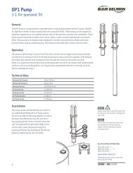
Design Dimensions in mm<br />
Reservoir<br />
Motor power<br />
A B C D<br />
8 litre Ø 190 595 785<br />
15 litre Ø 240 630 870<br />
30 litre Ø 310 700 1010<br />
0.18 kw, 63 min -1 406<br />
0.37 kw, 63 min -1 432<br />
0.37 kw, 125 min -1 424<br />
Page 5 of 10 BA_2005_2_GB_<strong>BM</strong>B
E. POSITION OF DRIVE<br />
without<br />
F. RESERVOIR<br />
8, 15 and 30 litres<br />
G. ACCESSORIES<br />
Level switch<br />
A level switch is available for the indication of the filling level in the reservoir. As sensor serves an<br />
ultrasonic sensor. As soon as the min. or max. level allowed has been obtained, a signal is released. With<br />
the help of a signal lamp at the reservoir, this signal can be used for the visual warning or for the control of<br />
an automatic filling facility. In case of receiving the order, we will attach particular operating instructions to<br />
the level switch with the following code: BA_2005_1_GB_76951_6011<br />
Pressure gauge<br />
Page 6 of 10 BA_2005_2_GB_<strong>BM</strong>B
3. Application<br />
The pump <strong>BM</strong>-B, because of the constructional characteristics, may be used in single line-, dual line-<br />
progressive- and spray lubricating systems.<br />
Regardless of the number of lubrication points, the pump <strong>BM</strong>-B can be effectively adapted to meet any<br />
requirements. It can also be used for refilling and mobile greasing systems.<br />
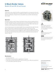
4. Design<br />
The pump consists of a housing together with the pump insert and the lubricant reservoir mounted on top.<br />
The pump insert has an integral pressure relief valve.<br />
The delivery and control plungers of the pump element are driven by eccentric cams to which they are<br />
rigidly connected. As a result there of, they are positively controlled.<br />
The required delivery pressure can be adjusted by means of an integrated pressure relief valve. It prevents<br />
damages to the pump in the event of an inadmissibly high counter-pressure situations. The pump <strong>BM</strong>-B<br />
need not be vented.<br />
* Pos. 42 Anziehdrehmoment 65 + 5 Nm<br />
* pos. 42 torque 65 + 5 Nm<br />
Page 7 of 10 BA_2005_2_GB_<strong>BM</strong>B<br />
*
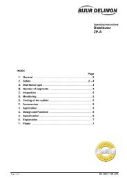
5. Principle of operation<br />
Reservoir with wedge plate assy. and scraper<br />
The wedge plate assy (17) is driven by the worm wheel (7, 25) and drive shaft. The grease is thus scraped<br />
off the wall of the reservoir and squeezed into the housing (4).<br />
<strong>Pump</strong> insert<br />
The pump insert is secured in the housing (4) by 5 screws (14, 22). It basically comprises a flange (44) with<br />
drive shaft (25) and the pump element with is fastened on top of the flange. Both control- (29) and feed<br />
plunger (31) of pump element are driven via an eccentric (28, 50, 51 and 47, 48, 49) running in ball<br />
bearings. The plungers are positively controlled in the eccentrics thus seizing (as usually occuring with<br />
spring-loaded plungers or with hydraulic pressure load) is prevented.<br />
Suction stroke<br />
At the start of the suction stroke, both control- and feed plunger are moved to the left whereby the feed<br />
plunger uncovers the suction port. The vacuum in conjunction with the slight overpressure of lubricant<br />
occuring inside the housing (4), causes the lubricant to be sucked via the control plunger bore and the<br />
suction port.<br />
Pressure stroke<br />
Now both the control- and feed plunger are moved to the right. This uncovers a connection via the annular<br />
groove of the control plunger between suction port and pressure channel so that the lubricant is forced by<br />
the feed plunger into the pressure channel.<br />
6. Specifications<br />
Discharge pressure adjustable, max. : ............................................................................................... 400 bar<br />
Discharge rate at : .............................. 63 min -1 : ........................................................ 34 cm 3 /min ( 2,0 l/h )<br />
125 min -1 : ........................................................ 67 cm 3 /min ( 4,0 l/h )<br />
Max. rpm : with motor : ........................................................................ 125 min -1<br />
Rotational direction of drive : ....................................................................................................................... left<br />
Reservoir capacity : ...................................................................................................................... 8, 15 or 30 l<br />
Operating temperature according to design : ...................................................................... - 20 o C to + 80 o C<br />
Compatible lubricants : ................................................................................... up to NLGI class 3, DIN 51818<br />
Mineral oils .................................................................................................... ISO VG 68 to 1500, DIN 51519<br />
Integral strainer : ................................................. strainer area 19 cm 2 , wire mesh size 0.4 x 0.18 DIN 4189<br />
Íntegral pressure relief valve : ........................................... adjustable from 0 to 450 bar, adjusted to 400 bar<br />
When using the hydraulic 4/2-way valve SAK, the set pressure may not exceed 350 bar.<br />
Page 8 of 10 BA_2005_2_GB_<strong>BM</strong>B
7. Start-up<br />
<strong>Pump</strong> installation<br />
Install the pump vertically. Then connect the motor to the control panel (refer to wiring diagram). Wire motor<br />
so as to ensure that fan runs anti-clockwise.<br />
Filling the reservoir and pipe lines<br />
Efficient operation demands the use of only clean lubricant! Contamination of the lubricant can lead to<br />
operation trouble and damage. The reservoir should only be re-charged via the filler plug provided,<br />
preferably use of a filling pump or grease gun, or from the works bulk supply system. The container must<br />
always be kept closed and care taken in ensuring that the lubricant is kept free from dirt and other<br />
contamination. Recharging of the container at the correct time most important, otherwise there is a risk of<br />
air finding its ways into the pump and main lines.To ensure trouble-free functioning the pump itself should<br />
be bled by operating it for a period without back pressure. As soon as the lubricant is discharged free of air<br />
bubbles from pressure connection (P), the feed lines can be connected. Run the pump then and continue to<br />
bleed all main lines, then connect pre-filled pipework to the metering elements.<br />
Connecting the pressure and relief lines<br />
The pressure outlet port at the flange (44) has a pipe connection of 3/8“ BSP female thread. When using<br />
the pump in a dual-line system, this branch is used to connect the 4/2-way reversing valve (and/or 3/2-way<br />
valves). On the housing (4) there is the pressure relief port of 3/“ BSP to connect the 4/2-way valve. In filling<br />
or greasing systems without a change-over valve, this port should be shut by a plug.<br />
8. Maintenance<br />
Strainer<br />
The strainer (35) should retain any contamination, which, by carelessness, has been allowed to get into the<br />
lubricant. Therefore check and clean with petrol or spirit the strainer at regular intervals. Any dirt therefore<br />
is retained inside the strainer (35) and will be removed when disassembling.<br />
ATTENTION<br />
A blinding filter due to pollution is leading to the bursting of the strainer.<br />
Pressure relief valve<br />
The integral pressure relief valve (56 to 65) protects the pumping element from damage. The pressure can<br />
be set according to system requirements from 0 to 400 bar. Turning the square spindle (56) clockwise the<br />
pressure is increased, and turning it anti-clockwise it is decreased. The relief valve is set by manufacturer’s<br />
to a pressure of 400 bar.<br />
ATTENTION<br />
The pressure rating adjusted at relief valve must not be higher than the max. admissible operating pressure<br />
of the elements installed downflow.<br />
Burst discs<br />
The respond of the burst plates protects the components of the system (e. g. pipes, fittings etc.) for<br />
overpressure.<br />
Two burst discs (24) are located in the stud (37) below the bush (41) which will rupture in the event of<br />
failure, or excessive pressure beyond 500 bar building up in the pressure channel in flange (44), e.g. if the<br />
relief valve (56 to 65) is clogged. When these discs burst, the lubricant issues out of the tube (43). In this<br />
case, first remedy the cause of failure and replace two new burst discs. Under the plug (23) in the flange<br />
(44) there are ten spare discs. When replacing new bursting discs take care that the curved face shows<br />
towards the bushing (41). If incorrectly fitted, the burst pressure is apt to be increased to such an extent<br />
causing in pump drive to be damaged.<br />
Page 9 of 10 BA_2005_2_GB_<strong>BM</strong>B
8. Maintenance (continuation)<br />
Geared motor or gear<br />
When being delivered, the geared motor or the gear is ready for operation and filled with oil ARAL Degol<br />
MB 680, which is suitable for an ambient temperature range from - 10 o C to - 20 o C. Refilling is not<br />
necessary, filling in excess is apt to heat the pump which is inadmissible. First oil change is recommended<br />
to take place at the end of 10,000 service hours. For a temperature range of -10 o C, we recommend -<br />
among other things - the oil type Degol <strong>BM</strong>B 220 of Aral. If the oil type recommended by us is not available,<br />
the following oil types can be used for a temperature range of up to -20 o C:<br />
Aral : Degol BG 220<br />
BP : Energol GR-xP 220<br />
Calypsol : Biesen Öl MSR 114<br />
Esso : Spartan EP 220<br />
Mobil : Mobilgear 630<br />
Shell : Omala 220<br />
Texaco : Meropa 220<br />
For temperatures below - 20 o C ARAL Degol <strong>BM</strong>B 46 (suitable down to - 45 o C) is recommended.<br />
The quantity to be recharged is 0.1 litre.<br />
9. Plates<br />
Do not mix lubricants with others; Clean gear thoroughtly with petrol or spirit before recharging<br />
with oil.<br />
Name plate Type plate<br />
Page 10 of 10 BA_2005_2_GB_<strong>BM</strong>B