Distributor PAG - Bijur Delimon
Distributor PAG - Bijur Delimon
Distributor PAG - Bijur Delimon

Create successful ePaper yourself
Turn your PDF publications into a flip-book with our unique Google optimized e-Paper software.
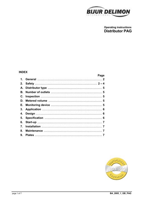
INDEX<br />
Page<br />
1. General ................................................................................. 2<br />
2. Safety .............................................................................. 2 – 4<br />
A. <strong>Distributor</strong> type .................................................................... 5<br />
B. Number of outlets ................................................................ 5<br />
C. Inspection ............................................................................. 5<br />
D. Metered volume ................................................................... 5<br />
E. Monitoring device ................................................................ 5<br />
3. Application ........................................................................... 6<br />
4. Design ................................................................................... 6<br />
5. Specification ........................................................................ 6<br />
6. Start-up ................................................................................. 7<br />
7. Installation ............................................................................ 7<br />
8. Maintenance ......................................................................... 7<br />
9. Plates .................................................................................... 7<br />
Operating instructions<br />
<strong>Distributor</strong> <strong>PAG</strong><br />
page 1 of 7 BA_2005_1_GB_<strong>PAG</strong>
1. General<br />
Prior to start up, we recommend to read these operating instructions carefully as we do not assume any<br />
liability for damages and operating troubles which result from the nonobservance of these operating<br />
instructions!<br />
Any use beyond the applications described in these operating instructions is considered to be not in<br />
accordance with the product’s intended purposes. The manufacturer is not to be held responsilbe for any<br />
damages resulting from this: the user alone bears the corresponding risk.<br />
As to figures and indications in these operating instructions we reserve the right to make technical changes<br />
which might become necessary for improvements.<br />
The copyright on these operating instructions is kept reserved to the company DELIMON. These operating<br />
instructions are intended for the erecting, the operating and supervising personnel. They contain<br />
regulations and drawings of technical nature which must not – completely or partially - be distributed nor<br />
used nor communicated to others without authorization for competition purposes.<br />
Company address, spare parts and service address<br />
DELIMON Branch office<br />
Arminstraße 15 Am Bockwald 4<br />
D-40277 Düsseldorf D-08344 Grünhain-Beierfeld<br />
Phone : +49 211 77 74-0 E-mail : kontakt@bijurdelimon.com<br />
Fax : +49 211 77 74-210 www.bijurdelimon.com<br />
2. Safety<br />
These operating instructions contain fundamental instructions which are to be observed during erection,<br />
operation and maintenance. Therefore it is absolutely necessary for the fitter and the competent qualified<br />
staff/user to read these operating instructions before installation and start-up. The operating instructions<br />
must be available at all times at the place of use of the machine/system.<br />
Not only the general safety instructions stated under this main point “safety“ are to be observed, but also<br />
the other specific safety instructions stated under the other main points.<br />
2.1 Identification of safety warnings in the operating instructions<br />
The safety warnings contained in these operating instructions which, if not observed, may cause dangers<br />
to people, are specially marked with general danger symbols<br />
safety sign according to DIN 4844, warning about a danger spot ,<br />
in case of warning about electric voltage with<br />
safety sign according to DIN 4844, warning about dangerous electric voltage.<br />
In case of safety instructions which, if not observed, may cause damage to the machine and its function,<br />
the word<br />
ATTENTION<br />
is inserted.<br />
Instructions that are directly attached to the machine, as for example<br />
• rotational direction arrow<br />
• identifications for fluid connections<br />
must be observed at all events and maintained in a fully legible condition.<br />
• Note: There is an increased skid risk in case of spilled/leaked out lubricants. They are to be removed<br />
at once properly.<br />
Safety sign according to DIN 4844, warning about skid risk.<br />
page 2 of 7 BA_2005_1_GB_<strong>PAG</strong>
2. Safety (continuation)<br />
2.2 Personnel qualification and training<br />
The operating, maintaining, inspecting and erecting personnel must have the appropriate qualification for<br />
such work. Area of responsibility, competence and supervision of the personnel have to be regulated by<br />
the user. If the personnel do not have the necessary knowledge, they have to be trained and given<br />
instructions. This can be effected, if necessary, by the manufacturer/supplier on behalf of the user of the<br />
machine. Furthermore, the user has to make sure that the contents of the operating instructions are fully<br />
understood by the personnel.<br />
2.3 Dangers in case of nonobservance of the safety instructions<br />
The nonobservance of the safety instructions may result in hazards to persons, to the environment and to<br />
the machine. The nonobservance of the safety instructions may lead to the loss of any claims for<br />
damages.<br />
In detail, the nonobservance may for instance lead to the following hazards:<br />
• Failure of important functions of the machine/system<br />
• Failure of prescribed methods for maintenance and repair<br />
• Harzard to persons by electrical, mechanical and chemical influences<br />
• Hazard to the environment by the leakage of dangerous substances<br />
2.4 Safety conscious working<br />
The safety instructions stated in these operating instructions, the existing national regulations as to the<br />
accident preventation as well as possible internal working, operating and safety rules of the user are to<br />
be observed.<br />
2.5 Safety instructions for the user/operator<br />
• If hot or cold machine parts lead to dangers, these parts have to be protected against touch.<br />
• Protection against touch for moving parts (e. g. coupling) must not be removed when the machine is<br />
in operation.<br />
• Leakages (e. g. from the shaft seal) of hazardous goods to be delivered (e. g. explosive, toxic, hot)<br />
are to be removed in such a way that there is no danger to persons and environment. Legal rules<br />
are to be ovserved. .<br />
• Hazards caused by electrial power are to be excluded (for details please refer for instance to the<br />
rules of the VDE and the local power supply companies).<br />
2.6 Safety instructions for maintenance, inspection and installation work<br />
The user has to take care that all the maintenance, inspection and installation work is executed by<br />
authorized and qualified skilled personnel who have informed themselves adequately by thoroughly<br />
studying the operating instructions.<br />
Basically, work on the machine is only to be carried out during shut-down. It is obligatory to observe the<br />
shut-down procedure described in the operating instructions .<br />
Pumps or pump aggregates that deliver media being hazardous to health have to be decontaminated.<br />
Immediately after completion of the work, all safety and protective equipments have to be reinstalled<br />
and/or reactivated.<br />
• Advice: When working with compressed air, do wear glasses.<br />
(DIN 4844 – Use breathing mask)<br />
• Advice: Observe EC-Safety Data Sheet for materials of consumption and additives used and use<br />
personal protective equipment.<br />
(DIN 4844 – Use breathing mask)<br />
Before recommissioning, observe the points stated in section “initial start-up“.<br />
2.7 Unauthorized conversion and manufacture of spare parts<br />
Conversion or modifications to the machine are only permitted when agreed with the manufacturer.<br />
Original spare parts and accessories authorized by the manufacturer serve to ensure safety. The use of<br />
other parts may render the liability for consequencial losses null and void.<br />
page 3 of 7 BA_2005_1_GB_<strong>PAG</strong>
2. Safety (continuation)<br />
2.8 Unacceptable modes of operation<br />
The operational reliability of the machine supplied is only guaranteed if the machine is used in<br />
accordance with its intended purposes as per section 1 - General - of the operating instructions. The<br />
limiting values specified in the data sheet must on no account be exceeded.<br />
2.9 Guidelines & standards<br />
1., 2. and 3. guideline (see data sheet: R&N_2009_1_GB)<br />
3.0 Notes on environmental protection and waste disposal<br />
In correct operation with lubricants, the components are subject to the special requirements set by<br />
environmental legislation.<br />
The general requirements for lubricants are specified in the respective safety data sheets.<br />
Used lubricants are hazardous forms of waste and therefore require special supervision in the sense of §<br />
41 paragraph 1 sentence 1 and paragraph 3 no. 1 of KrW-/AbfG (Closed-Loop Waste Management Act).<br />
Used oils must be handled in compliance with AltölV (Waste Oil Ordinance).<br />
The devices or components contaminated with lubricant must be disposed of by a certified waste<br />
management company.<br />
Records of proper waste management must be filed in conformance to NachwV (Ordinance on Waste<br />
Recovery and Disposal Records).<br />
page 4 of 7 BA_2005_1_GB_<strong>PAG</strong>
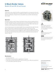
GENERAL PRODUCT CHARACTERISTICS<br />
• Dual-line manifold block<br />
• Grease and oil<br />
• up to 4 outlets<br />
• Metered volume continuously adjustable from 0.4 to 2.0 cm 3 per half cycle<br />
A. DISTRIBUTOR TYPE <strong>PAG</strong><br />
B. NUMBER OF OUTLETS<br />
1 – 4 outlets are possible.<br />
Outlets<br />
1 2 3 4<br />
Length I 48 80 112 144<br />
a 28 60 92 124<br />
C. INSPECTION<br />
Stage A<br />
D. METERED VOLUME<br />
Metered volume: 2.0 cm 3<br />
E. MONITORING DEVICE<br />
The metering valves are equipped with optical control unit which can be replaced by electric cintrol unit.<br />
page 5 of 7 BA_2005_1_GB_<strong>PAG</strong>
3. Application<br />
The distributors type <strong>PAG</strong> are used as lubricant manifolds in dual-line central systems. Due to their sturdy<br />
contruction and long service life, they are predominantly applied upon servicing and extending already<br />
existing systems with "<strong>PAG</strong> distributors“. The task of the distributors <strong>PAG</strong> consists in proportioning metered<br />
quantities of lubricant to the lubrication points.<br />
The distributors are conceived in building-block design. One control and metering piston each is allocated<br />
to every lubricating point (4 maximum). The housing block also accommodates the connections for main<br />
lines and lubricating points and has fastening holes. Actuation is effected by alternate pressurization of<br />
main lines I and II. Complete metering of all metering points of valve is finished after pressurizing main lines<br />
I and II.<br />
4. Design<br />
Pressure pulse in main line I (HL I)<br />
If main line I (HL I) is being pressurized, the lubricant will move the control piston (1) towards closure end<br />
plug (2). The lubricant is then led through channel (a) into chamber (c) pressing the metering piston (3)<br />
towards closure end plug (4). Lubricant provided in chamber (d) is delivered through channels (b) and (f) to<br />
the connection of lubricating point (e).<br />
Pressure pulse in main line II (HL II)<br />
If main line II (HL II) is being pressurized, the lubricant will move the control piston towards closure end<br />
plug (5). The lubricant is then led through channel (b) into chamber (d) pressing the metering piston against<br />
the stop (6). Lubricant provided in chamber (a) is delivered through channels (a) and (f) to the connection of<br />
lubricating point (e).<br />
A piston rod is fastened for optical control of functionality to the metering piston signalling the piston motios<br />
of control unit (7) due to alternate moving-in and moving-out motions. The optical control unit included in<br />
standard outfit simultaneously serves for infinite variation of metered quantity via threaded pins (8). Thus,<br />
the stroke of metering piston is restricted.<br />
Upon dispatch of metering valves, the metered quantity is set to maximum. Fastening of metering valves is<br />
ensured via welded plates.<br />
5. Specification<br />
Rated pressure: ................................................................................................................................... 400 bar<br />
Operation pressure max.: .................................................................................................................... 500 bar<br />
Pickup pressure: .................................................................................................................................... 40 bar<br />
Metered volume / lubricating-point connection: .................................... 0,4 ... 2 cm 3 continuously adjustable<br />
Installation position: ............................................................................................................................. optional<br />
Number of outlets: .................................................................................................................................. 1 to 4<br />
Temperature range: ............................................................................................................. - 30° C to + 80° C<br />
Consistency index: ....................................................................................... NLGI class 000 to 3, DIN 51818<br />
page 6 of 7 BA_2005_1_GB_<strong>PAG</strong>
6. Start-up<br />
Continuous adjustment of metered volume<br />
The reduction of the metered volume should preferably be made prior to the installation of the distributors.<br />
The following working processes are necessary:<br />
• Removal of headless pin (8) from the visual control facility<br />
• Adjustment of the stroke of the piston rod to the desired value by means of the second ring follower.<br />
(The stroke of the piston rod up the turned groove corresponds to a metered volume of 1 cm³).<br />
• Locking of this adjustment by means of the headless pin, which has been removed before.<br />
If it is necessary to change the metered volume at the installed distributor, perform the above described<br />
working processes after having switched off the centralized lubrication pump and take care that the piston<br />
rod is fully retracted.<br />
For the installation of the electric control facility, please refer to the particular installation instructions.<br />
At the version with electric control facility it is not possible to regulate the metered volume.<br />
7. Installation<br />
Install distributors in such a way that the distances between lubrication point and distributor are as short as<br />
possible, that the control of the indicator pin is possible and that the distributors are not twisted during<br />
installation (sticking of the metering and pilot pistons).<br />
It is possible to connect several distributors at the connection point of the main lines with the help of short<br />
pipe pieces. In this case, one can possibly do without individual fixing screws. For screwing down the<br />
distributors, it is essential for the realization of the wall distance being required for the screw fitting to use<br />
shim rings and/or weld plates.<br />
For the sealing of the screw fittings, which are required for the connection of the lubrication point lines, the<br />
use of distance rings is necessary.<br />
ATTENTION!<br />
Fastening torque for inlet fittings (M 16 x 1,5): max. 70 Nm<br />
Fastening torque for outlet fittings (M 14 x 1,5): max. 35 Nm<br />
8. Wartung<br />
The distributors are maintenance-free. It is not possible to exchange the metering or pilot pistons. In case<br />
of leakages at the external seal points, replace sealing elements. When the control facility is defective,<br />
replace the same as assembly group. Such a replacement is made as follows:<br />
• Switch off grease pump when indicator pin is fully extended.<br />
• Pressure relief of centralized lubrication system.<br />
• Dismount control facility from distributor and take it off together with the metering piston.<br />
• Separate control facility from metering piston by removing connecting element between indicator pin<br />
and metering piston.<br />
• Connect new control facility with the dismounted metering piston and refix control facility with metering<br />
piston to the distributor.<br />
Cleanliness is a very important factor for the above mentioned works.<br />
9. Plates<br />
Type plate 26 x 52mm (75511-1311)<br />
page 7 of 7 BA_2005_1_GB_<strong>PAG</strong>