High Availability Theoretical Basics - Schneider Electric
High Availability Theoretical Basics - Schneider Electric
High Availability Theoretical Basics - Schneider Electric

You also want an ePaper? Increase the reach of your titles
YUMPU automatically turns print PDFs into web optimized ePapers that Google loves.
Reliability Block Diagrams (RBD)<br />
Series-Parallel Systems<br />
<strong>High</strong> <strong>Availability</strong> <strong>Theoretical</strong> <strong>Basics</strong><br />
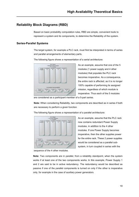
Based on basic probability computation rules, RBD are simple, convenient tools to<br />
represent a system and its components, to determine the Reliability of the system.<br />
The target system, for example a PLC rack, must first be interpreted in terms of series<br />
and parallel arrangements of elementary parts.<br />
The following figure shows a representation of a serial architecture:<br />
are considered as a participant member of a 5-part series.<br />
As an example, assume that one of the 5<br />
modules (1 power supply and 4 other<br />
modules) that populate the PLC rack<br />
becomes inoperative. As a consequence,<br />
the entire rack is affected, as it is no longer<br />
100% capable of performing its assigned<br />
mission, regardless of which module is<br />
inoperative. Thus each of the 5 modules<br />
Note: When considering Reliability, two components are described as in series if both<br />
are necessary to perform a given function.<br />
The following figure shows a representation of a parallel architecture:<br />
sequence of the 4 other modules.<br />
As an example, assume that the PLC rack<br />
now contains redundant Power Supply<br />
modules, in addition to the 4 other<br />
modules. If one Power Supply becomes<br />
inoperative, then the other supplies power<br />
for the entire rack. These 2 power supplies<br />
would be considered as a parallel sub-<br />
system, in turn coupled in series with the<br />
Note: Two components are in parallel, from a reliability standpoint, when the system<br />
works if at least one of the two components works. In this example, Power Supply 1<br />
and 2 are said to be in active redundancy. The redundancy would be described as<br />
passive if one of the parallel components is turned on only if the other is inoperative<br />
only, for example in the case of auxiliary power generators.<br />
19