- Page 1 and 2: Reference Manual CSI 2130 Machinery
- Page 3 and 4: Patents The product(s) described in
- Page 5: Software Technical Help Software Te
- Page 8 and 9: Chapter 3 • Data Transfer 8 Memor
- Page 10 and 11: 10 Input Setup . . . . . . . . . .
- Page 12 and 13: Precautions Any product damage due
- Page 14 and 15: Single- and Dual-Channel Versions o
- Page 16 and 17: 2130 2-channel volts adapter 1-chan
- Page 18 and 19: Unpacking the CSI 2130 Unpack the C
- Page 20 and 21: 4. Pull the plain end completely th
- Page 22 and 23: Panels In addition to the battery c
- Page 24 and 25: Charger Input Reset Switch This sma
- Page 26 and 27: Front Panel: Buttons, Indicators, a
- Page 28 and 29: Battery Use and Care A rechargeable
- Page 30 and 31: Screen for CSI 2130 with Ethernet P
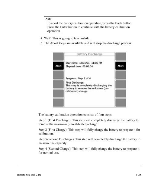
- Page 32 and 33: Note It is not necessary to press t
- Page 36 and 37: If the external power supply/charge
- Page 38 and 39: Changing the Battery To change the
- Page 40 and 41: 1-30 Introduction to the CSI 2130
- Page 42 and 43: Analyze and Advanced Analyze “Ana
- Page 44 and 45: 2. . .Press File Up and File Down t
- Page 46 and 47: Note Transferring files to and from
- Page 48 and 49: Select All Files: Selects all the f
- Page 50 and 51: Set Display Units Display Units def
- Page 52 and 53: Set dB Ref: Configure Acceleration,
- Page 54 and 55: USB Port Connection To begin using
- Page 56 and 57: Ethernet Card Connection Communicat
- Page 58 and 59: Disable DHCP to activate Set IP Add
- Page 60 and 61: Set Host Info: Enter the Host Name,
- Page 62 and 63: Note Do not change the Host Port ID
- Page 64 and 65: Select All Programs: Press to selec
- Page 66 and 67: Possible Base Firmware Error Messag
- Page 68 and 69: The screen below shows that the “
- Page 70 and 71: 3. . .With the CSI 2130 off, press
- Page 72 and 73: How do I .. Delete a Program? Cauti
- Page 74 and 75: From the Folders view, verify the c
- Page 76 and 77: ALT: Alternate Screens ALT Screen P
- Page 78 and 79: General Setup Use General Setup to
- Page 80 and 81: Set Backlight Time: Automatically d
- Page 82 and 83: Set Hold Time: determines the lengt
- Page 84 and 85:
Set Time Zone: Scroll through pages
- Page 86 and 87:
Erase PReg: clears the internal set
- Page 88 and 89:
Connect For Printing Connect For Pr
- Page 90 and 91:
Remote users of the CSI 2130 analyz
- Page 92 and 93:
The user may clear old information
- Page 94 and 95:
The CSI 2130 setup must match the "
- Page 96 and 97:
Install from a specific location 5.
- Page 98 and 99:
Note The exact format and content o
- Page 100 and 101:
Save data flagged bad reading: When
- Page 102 and 103:
Route Overrides The Route Overrides
- Page 104 and 105:
Change Point Definition For Firmwar
- Page 106 and 107:
Upon a successful connection, a new
- Page 108 and 109:
When the user has completed the dat
- Page 110 and 111:
If the auto-analyze option is enabl
- Page 112 and 113:
More than one report or plot may be
- Page 114 and 115:
The cover page is saved as part of
- Page 116 and 117:
Standalone Data Transfer Applicatio
- Page 118 and 119:
Model # Description Comments A06280
- Page 120 and 121:
Note Connect the D24860 triax cable
- Page 122 and 123:
Using a Route The simplest way to s
- Page 124 and 125:
Selecting Measurement Points There
- Page 126 and 127:
Route Data Collection The Route Dat
- Page 128 and 129:
Route Data Collection: Measurement
- Page 130 and 131:
• High Signal - When using DL-A t
- Page 132 and 133:
Previous Equipment takes you to the
- Page 134 and 135:
Field Alert places a field alert wa
- Page 136 and 137:
Fault Frequenciese Note The ID and
- Page 138 and 139:
Note If multiple data sets are stor
- Page 140 and 141:
User Setup User Setup allows you to
- Page 142 and 143:
Set HFD Averages: Opens a box where
- Page 144 and 145:
True Peak: Is obtained from the wav
- Page 146 and 147:
Group Status Timer: Control the aut
- Page 148 and 149:
New Sensor Power: If sensor power o
- Page 150 and 151:
Note Automatic display occurs only
- Page 152 and 153:
Unselect All Routes: Deselects all
- Page 154 and 155:
Print Route Report Printing a Route
- Page 156 and 157:
5-36 Route
- Page 158 and 159:
Notes Add Notes 4 To attach a note
- Page 160 and 161:
Up/Down Arrows: Allow you to scroll
- Page 162 and 163:
Downloading Routes and Uploading Da
- Page 164 and 165:
Once you have chosen a storage loca
- Page 166 and 167:
Multiple Route Load (MRL) allows Ro
- Page 168 and 169:
Time Discrepancy The time set on yo
- Page 170 and 171:
Analysis Experts Analysis Experts o
- Page 172 and 173:
• If data has already been collec
- Page 174 and 175:
Press the More Experts function key
- Page 176 and 177:
If the running speed is at a resona
- Page 178 and 179:
Order Tracking The Order Tracking e
- Page 180 and 181:
If Average Mode is set to “Synchr
- Page 182 and 183:
Using Analysis Experts Let this cha
- Page 184 and 185:
In Manual Analyze, you can set your
- Page 186 and 187:
You can set sensor parameters for b
- Page 188 and 189:
Change Sensor Type: Press this key
- Page 190 and 191:
Press Connect for Transfer to dump
- Page 192 and 193:
Press the Manual Analyze key on the
- Page 194 and 195:
Show RPM: Press Show RPM to display
- Page 196 and 197:
PeakVue passes the input signal thr
- Page 198 and 199:
Select Input: Use this dropdown men
- Page 200 and 201:
Set Spectra Params: Allows you to s
- Page 202 and 203:
Set Averaging: When vibration is me
- Page 204 and 205:
Waveform A vibration waveform is a
- Page 206 and 207:
Overall Setting the Analyze mode to
- Page 208 and 209:
DC Volts and Temperature. When meas
- Page 210 and 211:
For information about Tach Setup, S
- Page 212 and 213:
Set Center Frequency: This is the f
- Page 214 and 215:
Set Cascade Params: Use this menu t
- Page 216 and 217:
A minimum delay exists because of t
- Page 218 and 219:
Set Tach Start: This is only availa
- Page 220 and 221:
Set Average Enable: Select this fun
- Page 222 and 223:
The Analyze Setup Screen in Bandpas
- Page 224 and 225:
Cross Channel Phase Setting the Ana
- Page 226 and 227:
Plot Functions Use plotting tools t
- Page 228 and 229:
You can view up to four plots at on
- Page 230 and 231:
Store Data: Stores your data to a r
- Page 232 and 233:
Harmonic Family Cursors When this c
- Page 234 and 235:
Compress X Axis: Compresses the dis
- Page 236 and 237:
Cascade Plots Cascade acquisitions
- Page 238 and 239:
Auto Correlation Waveform plots hav
- Page 240 and 241:
When selected, the lines showing th
- Page 242 and 243:
Edit Job Setup Route Equipment: Job
- Page 244 and 245:
Delete Meas: Delete a measurement p
- Page 246 and 247:
If using USB or Serial connections,
- Page 248 and 249:
Analyze Mode Press Manual Analyze f
- Page 250 and 251:
Analyze Setup for Impact Mode Set S
- Page 252 and 253:
Note By default, the force hammer i
- Page 254 and 255:
Sensor Setup Sensor Setup screen wi
- Page 256 and 257:
Impact Acquisition Process Place th
- Page 258 and 259:
Clear Window Overlay: Removes the w
- Page 260 and 261:
Analyze Setup Setting up an Advance
- Page 262 and 263:
Two Channel Plot Setup Press Plot S
- Page 264 and 265:
Set Plot Options Explained Waveform
- Page 266 and 267:
The stacked plot option displays pl
- Page 268 and 269:
Applications and Insights Related t
- Page 270 and 271:
Resonance Explained Resonance is a
- Page 272 and 273:
The harder tips should be used when
- Page 274 and 275:
The phase measurement provides the
- Page 276 and 277:
Testing performed only to identify
- Page 278 and 279:
For the exploratory impacts try usi
- Page 280 and 281:
Summary Once a resonant frequency h
- Page 282 and 283:
CSI 2130 Advanced Transient Applica
- Page 284 and 285:
If data has been acquired on a poin
- Page 286 and 287:
Note The job manager mode is explai
- Page 288 and 289:
F7: This key will end the “Transi
- Page 290 and 291:
Changing Fmax adjusts the Sample Ra
- Page 292 and 293:
During data collection, the 2130 sc
- Page 294 and 295:
The Data Display Settings that can
- Page 296 and 297:
plot. Pressing the Scroll Left and
- Page 298 and 299:
F6: This key sets the format for ho
- Page 300 and 301:
ALT 2: F1: This key does not set RP
- Page 302 and 303:
F12: Pressing this key will compres
- Page 304 and 305:
Full Transient - Input: A Full Tran
- Page 306 and 307:
Orbit This overview is only a limit
- Page 308 and 309:
This is the Full transient Input B
- Page 310 and 311:
This is the Full transient Input B
- Page 312 and 313:
This is the Full transient Input B
- Page 314 and 315:
This is the Full transient Input B
- Page 316 and 317:
Order based colored Waterfall plot.
- Page 318 and 319:
Full Transient Input A + RPM plot +
- Page 320 and 321:
Hereinafter the term “structure
- Page 322 and 323:
All other functionalities are greye
- Page 324 and 325:
F4: Press this key to select the nu
- Page 326 and 327:
F6: Press this key to change the me
- Page 328 and 329:
Typical screen for an ODS job: 10-1
- Page 330 and 331:
Typical screen for an ODS/MODAL job
- Page 332 and 333:
F10: Press this key to switch betwe
- Page 334 and 335:
F3: Press this key to change the po
- Page 336 and 337:
10-18 ODS Modal
- Page 338 and 339:
Input Specifications Input Signals
- Page 340 and 341:
Prefilters The following filters ar
- Page 342 and 343:
CSI 2130 with Ethernet port and SD
- Page 344 and 345:
A-8 -
- Page 346 and 347:
G-2 Amplitude the magnitude (RMS, p
- Page 348 and 349:
G-4 If a quantity X is in RMS ampli
- Page 350 and 351:
G-6 ICM Influence Coefficient Metho
- Page 352 and 353:
G-8 Phase 1xRPM phase represents th
- Page 354 and 355:
G-10 Trigger causes the machinery a
- Page 356 and 357:
Coast Down Peak and Phase 6-8 Coast
- Page 358 and 359:
Cursor Type 7-49 Expand X 7-48, 7-5
- Page 360:
I-6