
Create successful ePaper yourself
Turn your PDF publications into a flip-book with our unique Google optimized e-Paper software.
<strong>GA</strong>-<strong>G41M</strong>-<strong>Combo</strong><br />
L<strong>GA</strong>775 socket motherboard for Intel ® Core processor family/<br />
Intel ® Pentium ® processor family/Intel ® Celeron ® processor family<br />
User's Manual<br />
Rev. 1302<br />
12ME-<strong>G41M</strong>C-1302R
May 24, 2010<br />
May 24, 2010<br />
Motherboard<br />
<strong>GA</strong>-<strong>G41M</strong>-<strong>Combo</strong><br />
Motherboard<br />
<strong>GA</strong>-<strong>G41M</strong>-<strong>Combo</strong>
Copyright<br />
© 2010 GI<strong>GA</strong>-BYTE TECHNOLOGY CO., LTD. All rights reserved.<br />
The trademarks mentioned in this manual are legally registered to their respective owners.<br />
Disclaimer<br />
Information in this manual is protected by copyright laws and is the property of GI<strong>GA</strong>BYTE.<br />
Changes to the specifications and features in this manual may be made by GI<strong>GA</strong>BYTE with-<br />
out prior notice. No part of this manual may be reproduced, copied, translated, transmitted, or<br />
published in any form or by any means without GI<strong>GA</strong>BYTE's prior written permission.<br />
Documentation Classifications<br />
In order to assist in the use of this product, GI<strong>GA</strong>BYTE provides the following types of documentations:<br />
� For detailed product information, carefully read the User's Manual.<br />
� For instructions on how to use GI<strong>GA</strong>BYTE's unique features, read or download the information<br />
on/from the Support&Downloads\Motherboard\Technology Guide page on our website.<br />
For product-related information, check on our website at:<br />
http://www.gigabyte.com<br />
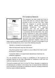
Identifying Your Motherboard Revision<br />
The revision number on your motherboard looks like this: "REV: X.X." For example, "REV: 1.0"<br />
means the revision of the motherboard is 1.0. Check your motherboard revision before updating<br />
motherboard BIOS, drivers, or when looking for technical information.<br />
Example:
Table of Contents<br />
<strong>GA</strong>-<strong>G41M</strong>-<strong>Combo</strong> Motherboard Layout ..........................................................................5<br />
Chapter 1 Hardware Installation .....................................................................................6<br />
1-1 Installation Precautions .................................................................................... 6<br />
1-2 Product Specifications ...................................................................................... 7<br />
1-3 Installing the CPU and CPU Cooler ................................................................. 9<br />
1-3-1 Installing the CPU .....................................................................................................9<br />
1-4 Installing the Memory ..................................................................................... 10<br />
1-4-1 Dual Channel Memory Configuration .....................................................................10<br />
1-5 Installing an Expansion Card ......................................................................... 10<br />
1-6 Back Panel Connectors .................................................................................. 11<br />
1-7 Internal Connectors ........................................................................................ 12<br />
Chapter 2 BIOS Setup ..................................................................................................21<br />
2-1 Startup Screen ............................................................................................... 21<br />
2-2 The Main Menu .............................................................................................. 21<br />
2-3 MB Intelligent Tweaker(M.I.T.) ........................................................................ 22<br />
2-4 Standard CMOS Features .............................................................................. 28<br />
2-5 Advanced BIOS Features .............................................................................. 29<br />
2-6 Advanced Chipset Features ........................................................................... 31<br />
2-7 Integrated Peripherals .................................................................................... 32<br />
2-8 Power Management Setup ............................................................................. 34<br />
2-9 PnP/PCI Configurations ................................................................................. 36<br />
2-10 PC Health Status ............................................................................................ 36<br />
2-11 Load Fail-Safe Defaults .................................................................................. 37<br />
2-12 Load Optimized Defaults ................................................................................ 38<br />
2-13 Set Supervisor/User Password ...................................................................... 38<br />
2-14 Save & Exit Setup .......................................................................................... 39<br />
2-15 Exit Without Saving ........................................................................................ 39<br />
Chapter 3 Drivers Installation ........................................................................................40<br />
3-1 Installing Chipset Drivers ............................................................................... 40<br />
Regulatory Statements ..................................................................................................41<br />
- 4 -
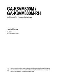
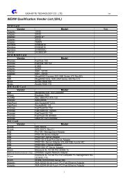
<strong>GA</strong>-<strong>G41M</strong>-<strong>Combo</strong> Motherboard Layout<br />
COMA<br />
V<strong>GA</strong><br />
KB_MS<br />
LPT<br />
R_USB<br />
USB_LAN<br />
AUDIO<br />
F_AUDIO<br />
Atheros<br />
AR8151<br />
iTE<br />
IT8718F<br />
CODEC<br />
CD_IN<br />
COMB<br />
SPDIF_O<br />
Box Contents<br />
ATX_12V<br />
PCI1<br />
PCI2<br />
FDD<br />
PCIEX1<br />
PCIEX16<br />
L<strong>GA</strong>775<br />
BAT<br />
Intel ® G41<br />
CLR_CMOS<br />
SYS_FAN<br />
CPU_FAN<br />
F_USB1<br />
B_BIOS<br />
- 5 -<br />
F_USB2<br />
<strong>GA</strong>-<strong>G41M</strong>-<strong>Combo</strong><br />
M_BIOS<br />
<strong>GA</strong>-<strong>G41M</strong>-<strong>Combo</strong> motherboard One IDE cable<br />
DDR3_1<br />
Intel ® ICH7<br />
Motherboard driver disk Two SATA cables<br />
DDR2_1<br />
User's Manual I/O Shield<br />
DDR2_2<br />
DDR3_2<br />
IDE<br />
SATA2_3<br />
SATA2_2<br />
SATA2_1<br />
SATA2_0<br />
The box contents above are for reference only and the actual items shall depend on the product package you obtain.<br />
The box contents are subject to change without notice.<br />
ATX<br />
F_PANEL
Chapter 1 Hardware Installation<br />
1-1 Installation Precautions<br />
The motherboard contains numerous delicate electronic circuits and components which can<br />
become damaged as a result of electrostatic discharge (ESD). Prior to installation, carefully read<br />
the user's manual and follow these procedures:<br />
• Prior to installation, do not remove or break motherboard S/N (Serial Number) sticker or<br />
warranty sticker provided by your dealer. These stickers are required for warranty validation.<br />
• Always remove the AC power by unplugging the power cord from the power outlet before<br />
installing or removing the motherboard or other hardware components.<br />
• When connecting hardware components to the internal connectors on the motherboard,<br />
make sure they are connected tightly and securely.<br />
• When handling the motherboard, avoid touching any metal leads or connectors.<br />
• It is best to wear an electrostatic discharge (ESD) wrist strap when handling electronic com-<br />
ponents such as a motherboard, CPU or memory. If you do not have an ESD wrist strap,<br />
keep your hands dry and first touch a metal object to eliminate static electricity.<br />
• Prior to installing the motherboard, please have it on top of an antistatic pad or within an<br />
electrostatic shielding container.<br />
• Before unplugging the power supply cable from the motherboard, make sure the power sup-<br />
ply has been turned off.<br />
• Before turning on the power, make sure the power supply voltage has been set according to<br />
the local voltage standard.<br />
• Before using the product, please verify that all cables and power connectors of your hard-<br />
ware components are connected.<br />
• To prevent damage to the motherboard, do not allow screws to come in contact with the<br />
motherboard circuit or its components.<br />
• Make sure there are no leftover screws or metal components placed on the motherboard or<br />
within the computer casing.<br />
• Do not place the computer system on an uneven surface.<br />
• Do not place the computer system in a high-temperature environment.<br />
• Turning on the computer power during the installation process can lead to damage to sys-<br />
tem components as well as physical harm to the user.<br />
• If you are uncertain about any installation steps or have a problem related to the use of the<br />
product, please consult a certified computer technician.<br />
Hardware Installation - 6 -
1-2 Product Specifications<br />
CPU w Support for an Intel ® Core 2 Extreme processor/<br />
Intel ® Core 2 Quad processor/Intel ® Core 2 Duo processor/<br />
Intel ® Pentium ® processor/Intel ® Celeron ® processor in the L<strong>GA</strong>775 package<br />
(Go to GI<strong>GA</strong>BYTE's website for the latest CPU support list.)<br />
w L2 cache varies with CPU<br />
Front Side Bus w 1333/1066/800 MHz FSB<br />
Chipset w North Bridge: Intel ® G41 Express Chipset<br />
w South Bridge: Intel ® ICH7<br />
Memory w DDR3:<br />
- 2 x 1.5V DDR3 DIMM sockets supporting up to 4 GB of system memory<br />
- Dual channel memory architecture<br />
- Support for DDR3 1333(O.C.)/1066/800 MHz memory modules<br />
w DDR2:<br />
- (Note 1)<br />
2 x 1.8V DDR2 DIMM sockets supporting up to 8 GB of system memory<br />
- Dual channel memory architecture<br />
- Support for DDR2 1066(O.C.)/800/667 MHz memory modules<br />
Onboard Graphics w<br />
(Note: Mixed mode, populating DDR2 and DDR3 memory modules simultaneously<br />
is not supported. Go to GI<strong>GA</strong>BYTE's website for the latest supported<br />
memory speeds and memory modules.)<br />
North Bridge:<br />
- 1 x D-Sub port<br />
Audio w VIA VT1708S codec<br />
w High Definition Audio<br />
w 2/4/5.1-channel<br />
w Support for S/PDIF Out<br />
w Support for CD In<br />
LAN w 1 x Atheros AR8151 chip (10/100/1000 Mbit)<br />
Expansion Slots w 1 x PCI Express x16 slot, running at x16<br />
w 1 x PCI Express x1 slot<br />
w 2 x PCI slots<br />
Storage Interface w South Bridge:<br />
- 1 x IDE connector supporting ATA-100/66/33 and up to 2 IDE devices<br />
- 4 x SATA 3Gb/s connectors supporting up to 4 SATA 3Gb/s devices<br />
w iTE IT8718F chip:<br />
- 1 x floppy disk drive connector supporting up to 1 floppy disk drive<br />
USB w South Bridge:<br />
- Up to 8 USB 2.0/1.1 ports (4 on the back panel, 4 via the USB brackets<br />
connected to the internal USB headers)<br />
Internal w 1 x 24-pin ATX main power connector<br />
Connectors w 1 x 4-pin ATX 12V power connector<br />
w 1 x floppy disk drive connector<br />
w 1 x IDE connector<br />
w 4 x SATA 3Gb/s connectors<br />
- 7 - Hardware Installation
Internal w 1 x CPU fan header<br />
Connectors w 1 x system fan header<br />
w 1 x front panel header<br />
w 1 x front panel audio header<br />
w 1 x CD In connector<br />
w 1 x S/PDIF Out header<br />
w 2 x USB 2.0/1.1 headers<br />
w 1 x serial port header<br />
w 1 x clearing CMOS jumper<br />
Back Panel w 1 x PS/2 keyboard port<br />
Connectors w 1 x PS/2 mouse port<br />
w 1 x parallel port<br />
w 1 x serial port<br />
w 1 x D-Sub port<br />
w 4 x USB 2.0/1.1 ports<br />
w 1 x RJ-45 port<br />
w 3 x audio jacks (Line In/Line Out/Microphone)<br />
I/O w iTE IT8718F<br />
Hardware Monitor w System voltage detection<br />
w CPU/System temperature detection<br />
w CPU/System fan speed detection<br />
w CPU overheating warning<br />
w CPU/System fan fail warning<br />
w (Note 2)<br />
CPU fan speed control<br />
BIOS w 2 x 8 Mbit flash<br />
w Use of licensed AWARD BIOS<br />
w Support for DualBIOS w PnP 1.0a, DMI 2.0, SM BIOS 2.4, ACPI 1.0b<br />
Unique Features w Support for @BIOS<br />
w Support for Q-Flash<br />
w Support for Xpress BIOS Rescue<br />
w Support for Download Center<br />
w Support for Xpress Install<br />
w Support for Xpress Recovery2<br />
w (Note 3)<br />
Support for EasyTune<br />
w (Note 4)<br />
Support for Easy Energy Saver<br />
w Support for SMART Recovery<br />
w Support for Auto Green<br />
w Support for ON/OFF Charge<br />
w Support for Q-Share<br />
Bundled Software w Norton Internet Security (OEM version)<br />
Operating System w Support for Microsoft ® Windows ® 7/Vista/XP<br />
Hardware Installation - 8 -
Form Factor w Micro ATX Form Factor; 24.4cm x 21.0cm<br />
(Note 1) Due to Windows 32-bit operating system limitation, when more than 4 GB of physical memory is<br />
installed, the actual memory size displayed will be less than 4 GB.<br />
(Note 2) Whether the CPU fan speed control function is supported will depend on the CPU cooler you install.<br />
(Note 3) Available functions in EasyTune may differ by motherboard model.<br />
(Note 4) Due to the hardware limitation, you must install the Intel ® Core TM 2 Extreme/Core TM 2 Quad/Core TM 2 Duo/<br />
Pentium Dual-Core/Celeron Dual-Core/Celeron 400 Series CPU to enable support for Easy Energy Saver.<br />
1-3 Installing the CPU and CPU Cooler<br />
Read the following guidelines before you begin to install the CPU:<br />
• Make sure that the motherboard supports the CPU.<br />
(Go to GI<strong>GA</strong>BYTE's website for the latest CPU support list.)<br />
• Always turn off the computer and unplug the power cord from the power outlet before installing<br />
the CPU to prevent hardware damage.<br />
• Locate the pin one of the CPU. The CPU cannot be inserted if oriented incorrectly. (Or you may<br />
locate the notches on both sides of the CPU and alignment keys on the CPU socket.)<br />
• Apply an even and thin layer of thermal grease on the surface of the CPU.<br />
• Do not turn on the computer if the CPU cooler is not installed, otherwise overheating and damage<br />
of the CPU may occur.<br />
• Set the CPU host frequency in accordance with the CPU specifications. It is not recommended<br />
that the system bus frequency be set beyond hardware specifications since it does not meet the<br />
standard requirements for the peripherals. If you wish to set the frequency beyond the standard<br />
specifications, please do so according to your hardware specifications including the CPU, graphics<br />
card, memory, hard drive, etc.<br />
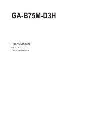
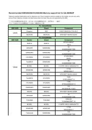
1-3-1 Installing the CPU<br />
Locate the alignment keys on the motherboard CPU socket and the notches on the CPU.<br />
L<strong>GA</strong>775 CPU Socket<br />
Alignment Key<br />
L<strong>GA</strong>775 CPU<br />
Notch Notch<br />
Alignment Key<br />
Pin One Corner of the CPU Socket<br />
Triangle Pin One Marking on the CPU<br />
- 9 - Hardware Installation
1-4 Installing the Memory<br />
Read the following guidelines before you begin to install the memory:<br />
• Make sure that the motherboard supports the memory. It is recommended that memory of the<br />
same capacity, brand, speed, and chips be used.<br />
(Go to GI<strong>GA</strong>BYTE's website for the latest supported memory speeds and memory modules.)<br />
• Always turn off the computer and unplug the power cord from the power outlet before installing<br />
the memory to prevent hardware damage.<br />
• Memory modules have a foolproof design. A memory module can be installed in only one direction.<br />
If you are unable to insert the memory, switch the direction.<br />
• Populating DDR2 and DDR3 memory modules simultaneously is not supported. To ensure memory<br />
compatibility, be sure to use the memory modules on the memory support list at GI<strong>GA</strong>BYTE's website.<br />
1-4-1 Dual Channel Memory Configuration<br />
This motherboard provides two DDR2 and two DDR3 memory sockets and supports Dual Channel Technology.<br />
The two DDR3 memory sockets (DDR3_1, DDR3_2) are divided into two channels and each channel has one<br />
memory socket as following:<br />
Channel 0: DDR3_1<br />
Channel 1: DDR3_2<br />
The two DDR2 memory sockets (DDR2_1, DDR2_2) are divided into two channels and each channel has one<br />
memory socket as following:<br />
Channel 0: DDR2_1<br />
Channel 1: DDR2_2<br />
DDR2_1<br />
DDR3_1<br />
DDR2_2<br />
DDR3_2<br />
DDR3/DDR2 Dual Channel Memory Configuration:<br />
Due to chipset limitations, read the following guidelines before installing the memory in Dual Channel mode.<br />
1. Dual Channel mode cannot be enabled if only one DDR3/DDR2 memory module is installed.<br />
2. When enabling Dual Channel mode with two memory modules, it is recommended that memory of<br />
the same capacity, brand, speed, and chips be used.<br />
1-5 Installing an Expansion Card<br />
Read the following guidelines before you begin to install an expansion card:<br />
• Make sure the motherboard supports the expansion card. Carefully read the manual that came<br />
with your expansion card.<br />
• Always turn off the computer and unplug the power cord from the power outlet before installing<br />
an expansion card to prevent hardware damage.<br />
Hardware Installation - 10 -
1-6 Back Panel Connectors<br />
PS/2 Keyboard and PS/2 Mouse Port<br />
Use the upper port (green) to connect a PS/2 mouse and the lower port (purple) to connect a PS/2 keyboard.<br />
Parallel Port<br />
Use the parallel port to connect devices such as a printer, scanner and etc. The parallel port is also<br />
called a printer port.<br />
Serial Port<br />
Use the serial port to connect devices such as a mouse, modem or other peripherals.<br />
D-Sub Port<br />
The D-Sub port supports a 15-pin D-Sub connector. Connect a monitor that supports D-Sub connection to this port.<br />
USB 2.0/1.1 Port<br />
The USB port supports the USB 2.0/1.1 specification. Use this port for USB devices such as a USB keyboard/mouse,<br />
USB printer, USB flash drive and etc.<br />
RJ-45 LAN Port<br />
The Gigabit Ethernet LAN port provides Internet connection at up to 1 Gbps data rate. The following describes<br />
the states of the LAN port LEDs.<br />
Connection/<br />
Speed LED<br />
LAN Port<br />
Activity LED<br />
Line In Jack (Blue)<br />
Connection/Speed LED:<br />
State Description<br />
Orange 1 Gbps data rate<br />
Green 100 Mbps data rate<br />
Off 10 Mbps data rate<br />
Activity LED:<br />
State Description<br />
Blinking Data transmission or receiving is occurring<br />
Off No data transmission or receiving is occurring<br />
The default line in jack. Use this audio jack for line in devices such as an optical drive, walkman, etc.<br />
Line Out Jack (Green)<br />
The default line out jack. Use this audio jack for a headphone or 2-channel speaker. This jack can be<br />
used to connect front speakers in a 4/5.1-channel audio configuration.<br />
Mic In Jack (Pink)<br />
The default Mic in jack. Microphones must be connected to this jack.<br />
• When removing the cable connected to a back panel connector, first remove the cable from your<br />
device and then remove it from the motherboard.<br />
• When removing the cable, pull it straight out from the connector. Do not rock it side to side to<br />
prevent an electrical short inside the cable connector.<br />
- 11 - Hardware Installation
1-7 Internal Connectors<br />
1) ATX_12V<br />
2) ATX<br />
3) CPU_FAN<br />
4) SYS_FAN<br />
5) FDD<br />
6) IDE<br />
7) SATA2_0/1/2/3<br />
8) F_PANEL<br />
13<br />
9<br />
15<br />
14<br />
Read the following guidelines before connecting external devices:<br />
• First make sure your devices are compliant with the connectors you wish to connect.<br />
• Before installing the devices, be sure to turn off the devices and your computer. Unplug the<br />
power cord from the power outlet to prevent damage to the devices.<br />
• After installing the device and before turning on the computer, make sure the device cable has<br />
been securely attached to the connector on the motherboard.<br />
Hardware Installation - 12 -<br />
1<br />
10 11<br />
5<br />
4<br />
3<br />
12<br />
7<br />
9) F_AUDIO<br />
10) CD_IN<br />
11) SPDIF_O<br />
12) F_USB1/F_USB2<br />
13) COMB<br />
14) CLR_CMOS<br />
15) BAT<br />
6<br />
2<br />
8
1/2) ATX_12V/ATX (2x2 12V Power Connector and 2x12 Main Power Connector)<br />
With the use of the power connector, the power supply can supply enough stable power to all the components<br />
on the motherboard. Before connecting the power connector, first make sure the power supply<br />
is turned off and all devices are properly installed. The power connector possesses a foolproof design.<br />
Connect the power supply cable to the power connector in the correct orientation. The 12V power connector<br />
mainly supplies power to the CPU. If the 12V power connector is not connected, the computer will<br />
not start.<br />
To meet expansion requirements, it is recommended that a power supply that can withstand<br />
high power consumption be used (500W or greater). If a power supply is used that does not<br />
provide the required power, the result can lead to an unstable or unbootable system.<br />
12<br />
1<br />
ATX<br />
24<br />
13<br />
ATX:<br />
Pin No. Definition<br />
3<br />
1<br />
1 3.3V<br />
2 3.3V<br />
3 GND<br />
4 +5V<br />
5 GND<br />
6 +5V<br />
7 GND<br />
8 Power Good<br />
9 5VSB (stand by +5V)<br />
10 +12V<br />
ATX_12V<br />
4<br />
11 +12V (Only for 2x12-pin ATX)<br />
12 3.3V (Only for 2x12-pin ATX)<br />
2<br />
ATX_12V:<br />
Pin No. Definition<br />
1 GND<br />
2 GND<br />
3 +12V<br />
4 +12V<br />
Pin No. Definition<br />
13 3.3V<br />
14 -12V<br />
15 GND<br />
16 PS_ON (soft On/Off)<br />
17 GND<br />
18 GND<br />
19 GND<br />
20 -5V<br />
21 +5V<br />
22 +5V<br />
23 +5V (Only for 2x12-pin ATX)<br />
24 GND (Only for 2x12-pin ATX)<br />
- 13 - Hardware Installation
3/4) CPU_FAN/SYS_FAN (Fan Headers)<br />
The motherboard has a 4-pin CPU fan header (CPU_FAN) and a 3-pin (SYS_FAN) system fan header.<br />
Most fan headers possess a foolproof insertion design. When connecting a fan cable, be sure to connect<br />
it in the correct orientation (the black connector wire is the ground wire). The motherboard supports CPU<br />
fan speed control, which requires the use of a CPU fan with fan speed control design. For optimum heat<br />
dissipation, it is recommended that a system fan be installed inside the chassis.<br />
• Be sure to connect fan cables to the fan headers to prevent your CPU and system from overheating.<br />
Overheating may result in damage to the CPU or the system may hang.<br />
• These fan headers are not configuration jumper blocks. Do not place a jumper cap on the<br />
headers.<br />
5) FDD (Floppy Disk Drive Connector)<br />
CPU_FAN<br />
Hardware Installation - 14 -<br />
1<br />
SYS_FAN<br />
CPU_FAN:<br />
Pin No. Definition<br />
1 GND<br />
2 +12V<br />
3 Sense<br />
4 Speed Control<br />
SYS_FAN:<br />
Pin No. Definition<br />
1 GND<br />
2 +12V<br />
3 Sense<br />
This connector is used to connect a floppy disk drive. The types of floppy disk drives supported are:<br />
360 KB, 720 KB, 1.2 MB, 1.44 MB, and 2.88 MB. Before connecting a floppy disk drive, be sure to locate<br />
pin 1 of the connector and the floppy disk drive cable. The pin 1 of the cable is typically designated by<br />
a stripe of different color. For purchasing the optional floppy disk drive cable, please contact the local<br />
dealer.<br />
33<br />
34<br />
1<br />
1<br />
2
6) IDE (IDE Connector)<br />
The IDE connector supports up to two IDE devices such as hard drives and optical drives. Before attaching<br />
the IDE cable, locate the foolproof groove on the connector. If you wish to connect two IDE devices,<br />
remember to set the jumpers and the cabling according to the role of the IDE devices (for example,<br />
master or slave). (For information about configuring master/slave settings for the IDE devices, read the<br />
instructions from the device manufacturers.)<br />
7) SATA2_0/1/2/3 (SATA 3Gb/s Connectors)<br />
The SATA connectors conform to SATA 3Gb/s standard and are compatible with SATA 1.5Gb/s standard.<br />
Each SATA connector supports a single SATA device.<br />
7<br />
SATA2_0<br />
SATA2_3<br />
SATA2_2 7<br />
SATA2_1 7<br />
1<br />
7<br />
40<br />
2<br />
1<br />
1<br />
1<br />
39<br />
1<br />
DEBUG<br />
PORT<br />
Pin No. Definition<br />
1 GND<br />
2 TXP<br />
3 TXN<br />
4 GND<br />
5 RXN<br />
6 RXP<br />
7 GND<br />
Please connect the L-shaped end of<br />
the SATA cable to your SATA hard<br />
drive.<br />
- 15 - Hardware Installation<br />
DEBUG<br />
PORT<br />
DEBUG<br />
PORT<br />
DEBUG<br />
PORT
8) F_PANEL (Front Panel Header)<br />
Connect the power switch, reset switch, speaker and system status indicator on the chassis front panel<br />
to this header according to the pin assignments below. Note the positive and negative pins before connecting<br />
the cables.<br />
Speaker<br />
Power<br />
Switch<br />
Message/Power/<br />
Sleep LED<br />
The front panel design may differ by chassis. A front panel module mainly consists of power<br />
switch, reset switch, power LED, hard drive activity LED, speaker and etc. When connecting your<br />
chassis front panel module to this header, make sure the wire assignments and the pin assignments<br />
are matched correctly.<br />
Hardware Installation - 16 -<br />
20 19<br />
SPEAK-<br />
SPEAK+<br />
PW-<br />
PW+<br />
MSG-<br />
MSG+<br />
�������<br />
2<br />
1<br />
PWR-<br />
PWR+<br />
CI+<br />
CI-<br />
RES+<br />
RES-<br />
HD-<br />
HD+<br />
Power LED<br />
Chassis Intrusion<br />
Header<br />
Reset<br />
Switch<br />
Hard Drive<br />
Activity LED<br />
• MSG/PWR (Message/Power/Sleep LED):<br />
System Status LED Connects to the power status indicator on the chassis front panel. The LED<br />
S0 On is on when the system is operating. The LED keeps blinking when the sys-<br />
S1 Blinking tem is in S1 sleep state. The LED is off when the system is in S3/S4 sleep<br />
S3/S4/S5 Off<br />
state or powered off (S5).<br />
• PW (Power Switch):<br />
Connects to the power switch on the chassis front panel. You may configure the way to turn off your<br />
system using the power switch (refer to Chapter 2, "BIOS Setup," "Power Management Setup," for<br />
more information).<br />
• SPEAK (Speaker):<br />
Connects to the speaker on the chassis front panel. The system reports system startup status by issuing<br />
a beep code. One single short beep will be heard if no problem is detected at system startup. If<br />
a problem is detected, the BIOS may issue beeps in different patterns to indicate the problem.<br />
• HD (Hard Drive Activity LED)<br />
Connects to the hard drive activity LED on the chassis front panel. The LED is on when the hard drive<br />
is reading or writing data.<br />
• RES (Reset Switch):<br />
Connects to the reset switch on the chassis front panel. Press the reset switch to restart the computer<br />
if the computer freezes and fails to perform a normal restart.<br />
• CI (Chassis Intrusion Header):<br />
Connects to the chassis intrusion switch/sensor on the chassis that can detect if the chassis cover<br />
has been removed. This function requires a chassis with a chassis intrusion switch/sensor.
9) F_AUDIO (Front Panel Audio Header)<br />
The front panel audio header supports Intel High Definition audio (HD) and AC'97 audio. You may connect<br />
your chassis front panel audio module to this header. Make sure the wire assignments of the module connector<br />
match the pin assignments of the motherboard header. Incorrect connection between the module<br />
connector and the motherboard header will make the device unable to work or even damage it.<br />
2 10<br />
1 9<br />
For HD Front Panel Audio: For AC'97 Front Panel Audio:<br />
Pin No. Definition<br />
Pin No. Definition<br />
1 MIC2_L<br />
2 GND<br />
3 MIC2_R<br />
4 -ACZ_DET<br />
5 LINE2_R<br />
6 GND<br />
7 FAUDIO_JD<br />
8 No Pin<br />
9 LINE2_L<br />
10 GND<br />
1 MIC<br />
2 GND<br />
3 MIC Power<br />
4 NC<br />
5 Line Out (R)<br />
6 NC<br />
7 NC<br />
8 No Pin<br />
9 Line Out (L)<br />
10 NC<br />
• The front panel audio header supports HD audio by default.<br />
• Audio signals will be present on both of the front and back panel audio connections simultaneously.<br />
• Some chassis provide a front panel audio module that has separated connectors on each wire<br />
instead of a single plug. For information about connecting the front panel audio module that<br />
has different wire assignments, please contact the chassis manufacturer.<br />
10) CD_IN (CD In Connector)<br />
You may connect the audio cable that came with your optical drive to the header.<br />
1<br />
Pin No. Definition<br />
1 CD-L<br />
2 GND<br />
3 GND<br />
4 CD-R<br />
- 17 - Hardware Installation
11) SPDIF_O (S/PDIF Out Header)<br />
This header supports digital S/PDIF Out and connects a S/PDIF digital audio cable (provided by expansion<br />
cards) for digital audio output from your motherboard to certain expansion cards like graphics cards<br />
and sound cards. For example, some graphics cards may require you to use a S/PDIF digital audio cable<br />
for digital audio output from your motherboard to your graphics card if you wish to connect an HDMI<br />
display to the graphics card and have digital audio output from the HDMI display at the same time. For<br />
information about connecting the S/PDIF digital audio cable, carefully read the manual for your expansion<br />
card.<br />
12) F_USB1/F_USB2 (USB Headers)<br />
The headers conform to USB 2.0/1.1 specification. Each USB header can provide two USB ports via an<br />
optional USB bracket. For purchasing the optional USB bracket, please contact the local dealer.<br />
Hardware Installation - 18 -<br />
9<br />
10<br />
1<br />
Pin No. Definition<br />
1 Power (5V)<br />
2 Power (5V)<br />
3 USB DX-<br />
4 USB DY-<br />
5 USB DX+<br />
6 USB DY+<br />
7 GND<br />
8 GND<br />
9 No Pin<br />
10 NC<br />
• Do not plug the IEEE 1394 bracket (2x5-pin) cable into the USB header.<br />
• Prior to installing the USB bracket, be sure to turn off your computer and unplug the power<br />
cord from the power outlet to prevent damage to the USB bracket.<br />
1<br />
2<br />
Pin No. Definition<br />
1 SPDIFO<br />
2 GND
13) COMB (Serial Port Header)<br />
The COM header can provide one serial port via an optional COM port cable. For purchasing the optional<br />
COM port cable, please contact the local dealer.<br />
14) CLR_CMOS (Clearing CMOS Jumper)<br />
1<br />
9<br />
Pin No. Definition<br />
1 NDCD-<br />
2 NSIN<br />
3 NSOUT<br />
4 NDTR-<br />
5 GND<br />
6 NDSR-<br />
7 NRTS-<br />
8 NCTS-<br />
9 NRI-<br />
10 No Pin<br />
Use this jumper to clear the CMOS values (e.g. date information and BIOS configurations) and reset<br />
the CMOS values to factory defaults. To clear the CMOS values, place a jumper cap on the two pins to<br />
temporarily short the two pins or use a metal object like a screwdriver to touch the two pins for a few<br />
seconds.<br />
2<br />
10<br />
Open: Normal<br />
Short: Clear CMOS Values<br />
• Always turn off your computer and unplug the power cord from the power outlet before clearing<br />
the CMOS values.<br />
• After clearing the CMOS values and before turning on your computer, be sure to remove the<br />
jumper cap from the jumper. Failure to do so may cause damage to the motherboard.<br />
• After system restart, go to BIOS Setup to load factory defaults (select Load Optimized<br />
Defaults) or manually configure the BIOS settings (refer to Chapter 2, "BIOS Setup," for BIOS<br />
configurations).<br />
- 19 - Hardware Installation
15) BAT(Battery)<br />
The battery provides power to keep the values (such as BIOS configurations, date, and time information)<br />
in the CMOS when the computer is turned off. Replace the battery when the battery voltage drops to a<br />
low level, or the CMOS values may not be accurate or may be lost.<br />
Hardware Installation - 20 -<br />
You may clear the CMOS values by removing the battery:<br />
1. Turn off your computer and unplug the power cord.<br />
2. Gently remove the battery from the battery holder and wait for one<br />
minute. (Or use a metal object like a screwdriver to touch the positive<br />
and negative terminals of the battery holder, making them short for 5<br />
seconds.)<br />
3. Replace the battery.<br />
4. Plug in the power cord and restart your computer.<br />
• Always turn off your computer and unplug the power cord before replacing the battery.<br />
• Replace the battery with an equivalent one. Danger of explosion if the battery is replaced with<br />
an incorrect model.<br />
• Contact the place of purchase or local dealer if you are not able to replace the battery by yourself<br />
or uncertain about the battery model.<br />
• When installing the battery, note the orientation of the positive side (+) and the negative side (-)<br />
of the battery (the positive side should face up).<br />
• Used batteries must be handled in accordance with local environmental regulations.
Chapter 2 BIOS Setup<br />
To access the BIOS Setup program, press the key during the POST when the power is turned on.<br />
To see more advanced BIOS Setup menu options, you can press + in the main menu of the<br />
BIOS Setup program.<br />
To upgrade the BIOS, use either the GI<strong>GA</strong>BYTE Q-Flash or @BIOS utility.<br />
• Q-Flash allows the user to quickly and easily upgrade or back up BIOS without entering the operating<br />
system.<br />
• @BIOS is a Windows-based utility that searches and downloads the latest version of BIOS from the<br />
Internet and updates the BIOS.<br />
• Because BIOS flashing is potentially risky, if you do not encounter problems using the current<br />
version of BIOS, it is recommended that you not flash the BIOS. To flash the BIOS, do it with<br />
caution. Inadequate BIOS flashing may result in system malfunction.<br />
• It is recommended that you not alter the default settings (unless you need to) to prevent system<br />
instability or other unexpected results. Inadequately altering the settings may result in system's<br />
failure to boot. If this occurs, try to clear the CMOS values and reset the board to default values.<br />
(Refer to the "Load Optimized Defaults" section in this chapter or introductions of the battery/<br />
clearing CMOS jumper in Chapter 1 for how to clear the CMOS values.)<br />
2-1 Startup Screen<br />
The following screens may appear when the computer boots.<br />
Motherboard Model<br />
BIOS Version<br />
Award Modular BIOS v6.00PG, An Energy Star Ally<br />
Copyright (C) 1984-2010, Award Software, Inc.<br />
<strong>G41M</strong>-<strong>Combo</strong> E20c<br />
.<br />
.<br />
.<br />
.<br />
2-2 The Main Menu<br />
: BIOS Setup : XpressRecovery2 : Boot Menu : Qflash<br />
05/07/2010-G41-ICH7-6A79PG0FC-00<br />
Function Keys<br />
Once you enter the BIOS Setup program, the Main Menu (as shown below) appears on the screen. Use arrow<br />
keys to move among the items and press to accept or enter a sub-menu.<br />
(Sample BIOS Version: E20c)<br />
� MB Intelligent Tweaker(M.I.T.)<br />
� Standard CMOS Features<br />
� Advanced BIOS Features<br />
� Advanced Chipset Features<br />
� Integrated Peripherals<br />
� Power Management Setup<br />
� PnP/PCI Configurations<br />
CMOS Setup Utility-Copyright (C) 1984-2010 Award Software<br />
Change CPU's Clock & Voltage<br />
� PC Health Status<br />
Load Fail-Safe Defaults<br />
Load Optimized Defaults<br />
Set Supervisor Password<br />
Set User Password<br />
Save & Exit Setup<br />
Exit Without Saving<br />
ESC: Quit ����: Select Item F11: Save CMOS to BIOS<br />
F8: Q-Flash F10: Save & Exit Setup F12: Load CMOS from BIOS<br />
- 21 - BIOS Setup
• If you do not find the settings you want in the Main Menu or a submenu, press + to<br />
access more advanced options.<br />
• When the system is not stable as usual, select the Load Optimized Defaults item to set your<br />
system to its defaults.<br />
• The BIOS Setup menus described in this chapter are for reference only and may differ by BIOS<br />
version.<br />
� The Functions of the and keys (For the Main Menu Only)<br />
� F11: Save CMOS to BIOS<br />
This function allows you to save the current BIOS settings to a profile. You can create up to 8 profiles<br />
(Profile 1-8) and name each profile. First enter the profile name (to erase the default profile name, use<br />
the SPACE key) and then press to complete.<br />
� F12: Load CMOS from BIOS<br />
If your system becomes unstable and you have loaded the BIOS default settings, you can use this<br />
function to load the BIOS settings from a profile created before, without the hassles of reconfiguring the<br />
BIOS settings. First select the profile you wish to load, then press to complete.<br />
2-3 MB Intelligent Tweaker(M.I.T.)<br />
CMOS Setup Utility-Copyright (C) 1984-2010 Award Software<br />
MB Intelligent Tweaker(M.I.T.)<br />
Robust Graphics Booster [Auto]<br />
CPU Clock Ratio (Note) [15X]<br />
Fine CPU Clock Ratio (Note) [+0.0]<br />
CPU Frequency 3.00GHz ( 200x15)<br />
******** Clock Chip Control ********<br />
>>>>> Standard Clock Control<br />
CPU Host Clock Control [Disabled]<br />
x CPU Host Frequency (Mhz) 200<br />
PCI Express Frequency (Mhz) [Auto]<br />
>>>>> Advanced Clock Control<br />
******** DRAM Performance Control ********<br />
Performance Enhance [Standard]<br />
(G)MCH Frequency Latch [Auto]<br />
System Memory Multiplier (SPD) [Auto]<br />
Memory Frequency (Mhz) 1333 800<br />
DRAM Timing Selectable (SPD) [Auto]<br />
>>>>> Standard Timing Control<br />
����: Move Enter: Select +/-/PU/PD: Value F10: Save ESC: Exit F1: General Help<br />
F5: Previous Values F6: Fail-Safe Defaults F7: Optimized Defaults<br />
(Note) This item appears only if you install a CPU that supports this feature.<br />
BIOS Setup - 22 -<br />
Item Help<br />
Menu Level �
CMOS Setup Utility-Copyright (C) 1984-2010 Award Software<br />
MB Intelligent Tweaker(M.I.T.)<br />
x CAS Latency Time 9 Auto<br />
x tRCD 9 Auto<br />
x tRP 9 Auto<br />
x tRAS 24 Auto<br />
>>>>> Advanced Timing Control<br />
� Advanced Timing Control [Press Enter]<br />
******** Mother Board Voltage Control ********<br />
Voltage Types Normal Current<br />
-----------------------------------------------------------------------------<br />
>>> CPU<br />
CPU Vcore 1.375V [Auto]<br />
CPU Termination 1.200V [Auto]<br />
>>> DRAM<br />
DRAM Voltage 1.500V [Auto]<br />
����: Move Enter: Select +/-/PU/PD: Value F10: Save ESC: Exit F1: General Help<br />
F5: Previous Values F6: Fail-Safe Defaults F7: Optimized Defaults<br />
Whether the system will work stably with the overclock/overvoltage settings you made is dependent<br />
on your overall system configurations. Incorrectly doing overclock/overvoltage may result in damage<br />
to CPU, chipset, or memory and reduce the useful life of these components. This page is for<br />
advanced users only and we recommend you not to alter the default settings to prevent system<br />
instability or other unexpected results. (Inadequately altering the settings may result in system's<br />
failure to boot. If this occurs, clear the CMOS values and reset the board to default values.)<br />
Robust Graphics Booster<br />
(Note) This item appears only if you install a CPU that supports this feature.<br />
Item Help<br />
Menu Level �<br />
Robust Graphics Booster (R.G.B.) helps to enhance the performance of the graphics chip and memory.<br />
Auto allows the BIOS to automatically set the R.G.B. mode based on system configurations. Options<br />
are: Auto (default), Fast, Turbo.<br />
CPU Clock Ratio (Note)<br />
Allows you to alter the clock ratio for the installed CPU.<br />
The item is present only if a CPU with unlocked clock ratio is installed.<br />
Fine CPU Clock Ratio (Note)<br />
Allows you to increase clock ratio by 0.5 for the installed CPU.<br />
The item is present only if a CPU with unlocked clock ratio is installed.<br />
CPU Frequency<br />
Displays the current operating CPU frequency.<br />
******** Clock Chip Control ********<br />
>>>>> Standard Clock Control<br />
CPU Host Clock Control<br />
Enables or disables the control of CPU host clock. Enabled will allow the CPU Host Frequency item<br />
below to be configurable. Note: If your system fails to boot after overclocking, please wait for 20 seconds<br />
to allow for automated system reboot, or clear the CMOS values to reset the board to default values.<br />
(Default: Disabled)<br />
- 23 - BIOS Setup
CPU Host Frequency (Mhz)<br />
Allows you to manually set the CPU host frequency. The adjustable range is from 100 MHz to 1200 MHz.<br />
This item is configurable only if the CPU Host Clock Control option is enabled.<br />
Important: It is highly recommended that the CPU frequency be set in accordance with the CPU<br />
specifications.<br />
PCI Express Frequency (Mhz)<br />
Allows you to manually set the PCIe clock frequency. The adjustable range is from 90 MHz to 150 MHz.<br />
Auto sets the PCIe clock frequency to standard 100 MHz. (Default: Auto)<br />
******** DRAM Performance Control ********<br />
Performance Enhance<br />
Allows the system to operate at three different performance levels.<br />
Standard Lets the system operate at its basic performance level. (Default)<br />
Turbo Lets the system operate at its good performance level.<br />
Extreme Lets the system operate at its best performance level.<br />
(G)MCH Frequency Latch<br />
Allows you to fix the chipset frequency at system bootup. Options for adjusting memory multiplier below<br />
may differ according to the fixed frequency. Options are: Auto (default), 200MHz, 266MHz, 333MHz.<br />
System Memory Multiplier (SPD)<br />
Allows you to set the system memory multiplier. Options are dependent on CPU FSB and the (G)MCH<br />
Frequency Latch settings. Auto sets memory multiplier according to memory SPD data. (Default: Auto)<br />
Memory Frequency (Mhz)<br />
The first memory frequency value is the normal operating frequency of the memory being used; the<br />
second is the memory frequency that is automatically adjusted according to the CPU Host Frequency<br />
(Mhz) and System Memory Multiplier settings.<br />
DRAM Timing Selectable (SPD)<br />
Manual allows all DRAM timing control items below to be configurable. Options are: Auto (default),<br />
Manual.<br />
>>>>> Standard Timing Control<br />
CAS Latency Time<br />
Options are: Auto (default), 4~11.<br />
tRCD<br />
Options are: Auto (default), 1~15.<br />
tRP<br />
Options are: Auto (default), 1~15.<br />
tRAS<br />
Options are: Auto (default), 1~63.<br />
>>>>> Advanced Timing Control<br />
Advanced Timing Control<br />
BIOS Setup - 24 -
tRRD<br />
Options are: Auto (default), 1~15.<br />
tWTR<br />
Options are: Auto (default), 1~31.<br />
tWR<br />
Options are: Auto (default), 1~31.<br />
tRFC<br />
Options are: Auto (default), 1~255.<br />
tRTP<br />
Options are: Auto (default), 1~15.<br />
Command Rate(CMD)<br />
Options are: Auto (default), 1~3.<br />
>>>>> Channel A/B<br />
Channel A/B Timing Settings<br />
CMOS Setup Utility-Copyright (C) 1984-2010 Award Software<br />
Advanced Timing Control<br />
x tRRD Auto<br />
x tWTR Auto<br />
x tWR Auto<br />
x tRFC Auto<br />
x tRTP Auto<br />
x Command Rate (CMD) Auto<br />
>>>>> Channel A<br />
� Channel A Timing Settings [Press Enter]<br />
� Channel A Driving Settings [Press Enter]<br />
>>>>> Channel B<br />
� Channel B Timing Settings [Press Enter]<br />
� Channel B Driving Settings [Press Enter]<br />
Item Help<br />
Menu Level ��<br />
����: Move Enter: Select +/-/PU/PD: Value F10: Save ESC: Exit F1: General Help<br />
F5: Previous Values F6: Fail-Safe Defaults F7: Optimized Defaults<br />
CMOS Setup Utility-Copyright (C) 1984-2010 Award Software<br />
Channel A/B Timing Settings<br />
x Static tRead Value Auto<br />
x tRD Phase0 Adjustment Auto<br />
x tRD Phase1 Adjustment Auto<br />
x tRD Phase2 Adjustment Auto<br />
x tRD Phase3 Adjustment Auto<br />
x Trd2rd(Different Rank) Auto<br />
x Twr2wr(Different Rank) Auto<br />
x Twr2rd(Different Rank) Auto<br />
x Trd2wr(Same/Diff Rank) Auto<br />
x DIMM1 Clock Skew Control Auto<br />
x DIMM2 Clock Skew Control Auto<br />
x DDR Write Leveling Auto<br />
x DDR Write Training Auto<br />
Item Help<br />
Menu Level ���<br />
����: Move Enter: Select +/-/PU/PD: Value F10: Save ESC: Exit F1: General Help<br />
F5: Previous Values F6: Fail-Safe Defaults F7: Optimized Defaults<br />
- 25 - BIOS Setup
Static tRead Value<br />
Options are: Auto (default), 1~15.<br />
tRD Phase0 Adjustment<br />
Options are: Auto (default), 0-Normal, 1-Advanced.<br />
tRD Phase1 Adjustment<br />
Options are: Auto (default), 0-Normal, 1-Advanced.<br />
tRD Phase2 Adjustment<br />
Options are: Auto (default), 0-Normal, 1-Advanced.<br />
tRD Phase3 Adjustment<br />
Options are: Auto (default), 0-Normal, 1-Advanced.<br />
Trd2rd(Different Rank)<br />
Options are: Auto (default), 1~15.<br />
Twr2wr(Different Rank)<br />
Options are: Auto (default), 1~15.<br />
Twr2rd(Different Rank)<br />
Options are: Auto (default), 1~15.<br />
Trd2wr(Same/Diff Rank)<br />
Options are: Auto (default), 1~15.<br />
DIMM1 Clock Skew Control<br />
Options are: Auto (default), +800ps~-700ps.<br />
DIMM2 Clock Skew Control<br />
Options are: Auto (default), +800ps~-700ps.<br />
DDR Write Leveling<br />
Allows you to determine whether to fine-tune memory parameters to enhance memory compatibility.<br />
Auto Lets the BIOS decide whether to enable this function. (Default)<br />
Enabled Enables this function to enhance memory compatibility.<br />
Disabled Disables this function.<br />
DDR Write Training<br />
Allows you to determine whether to fine-tune memory parameters to enhance memory compatibility.<br />
Auto Lets the BIOS decide whether to enable this function. (Default)<br />
Enabled Enables this function to enhance memory compatibility.<br />
Disabled Disables this function.<br />
Channel A/B Driving Settings<br />
BIOS Setup - 26 -
Driving Strength Profile<br />
Options are: Auto (default).<br />
Data Driving Pull-Up Level<br />
Options are: Auto (default), +8~-7.<br />
Cmd Driving Pull-Up Level<br />
Options are: Auto (default), +8~-7.<br />
Ctrl Driving Pull-Up Level<br />
Options are: Auto (default), +8~-7.<br />
Clk Driving Pull-Up Level<br />
Options are: Auto (default), +8~-7.<br />
Data Driving Pull-Down Level<br />
Options are: Auto (default), +8~-7.<br />
Cmd Driving Pull-Down Level<br />
Options are: Auto (default), +8~-7.<br />
Ctrl Driving Pull-Down Level<br />
Options are: Auto (default), +8~-7.<br />
Clk Driving Pull-Down Level<br />
Options are: Auto (default), +8~-7.<br />
******** Mother Board Voltage Control ********<br />
>>> CPU<br />
CPU Vcore<br />
The default is Auto.<br />
CPU Termination<br />
The default is Auto.<br />
>>> DRAM<br />
DRAM Voltage<br />
The default is Auto.<br />
CMOS Setup Utility-Copyright (C) 1984-2010 Award Software<br />
Channel A/B Driving Settings<br />
x Driving Strength Profile Auto<br />
x Data Driving Pull-Up Level Auto<br />
x Cmd Driving Pull-Up Level Auto<br />
x Ctrl Driving Pull-Up Level Auto<br />
x Clk Driving Pull-Up Level Auto<br />
x Data Driving Pull-Down Level Auto<br />
x Cmd Driving Pull-Down Level Auto<br />
x Ctrl Driving Pull-Down Level Auto<br />
x Clk Driving Pull-Down Level Auto<br />
Item Help<br />
Menu Level ���<br />
����: Move Enter: Select +/-/PU/PD: Value F10: Save ESC: Exit F1: General Help<br />
F5: Previous Values F6: Fail-Safe Defaults F7: Optimized Defaults<br />
- 27 - BIOS Setup
2-4 Standard CMOS Features<br />
Date (mm:dd:yy)<br />
Sets the system date.<br />
Time (hh:mm:ss)<br />
Sets the system time.<br />
IDE Channel 0, 2, 3 Master/Slave<br />
CMOS Setup Utility-Copyright (C) 1984-2010 Award Software<br />
Standard CMOS Features<br />
Date (mm:dd:yy) Mon, May 10 2010<br />
Time (hh:mm:ss) 22:31:24<br />
� IDE Channel 0 Master [None]<br />
� IDE Channel 0 Slave [None]<br />
� IDE Channel 2 Master [None]<br />
� IDE Channel 2 Slave [None]<br />
� IDE Channel 3 Master [None]<br />
� IDE Channel 3 Slave [None]<br />
Drive A [1.44M, 3.5"]<br />
Floppy 3 Mode Support [Disabled]<br />
Halt On [All, But Keyboard]<br />
Base Memory 640K<br />
Extended Memory 2012M<br />
Total Memory 2014M<br />
����: Move Enter: Select +/-/PU/PD: Value F10: Save ESC: Exit F1: General Help<br />
F5: Previous Values F6: Fail-Safe Defaults F7: Optimized Defaults<br />
IDE HDD Auto-Detection, IDE Auto-Detection<br />
Press to autodetect the parameters of the IDE/SATA device on this channel.<br />
IDE Channel 0 Master/Slave, Extended IDE Drive<br />
Configure your IDE/SATA devices by using one of the three methods below:<br />
• Auto Lets the BIOS automatically detect IDE/SATA devices during the POST. (Default)<br />
• None If no IDE/SATA devices are used, set this item to None so the system will skip the<br />
detection of the device during the POST for faster system startup.<br />
• Manual Allows you to manually enter the specifications of the hard drive when the hard drive<br />
access mode is set to CHS. (For IDE Channel 0 Master/Slave only.)<br />
Access Mode Sets the hard drive access mode. (Default: Auto)<br />
The following fields display your hard drive specifications. If you wish to enter the parameters manually,<br />
refer to the information on the hard drive.<br />
Capacity Approximate capacity of the currently installed hard drive.<br />
Cylinder Number of cylinders.<br />
Head Number of heads.<br />
Precomp Write precompensation cylinder.<br />
Landing Zone Landing zone.<br />
Sector Number of sectors.<br />
Drive A<br />
Allows you to select the type of floppy disk drive installed in your system. If you do not install a floppy<br />
disk drive, set this item to None. Options are: None, 360K/5.25", 1.2M/5.25", 720K/3.5", 1.44M/3.5",<br />
2.88M/3.5".<br />
BIOS Setup - 28 -<br />
Item Help<br />
Menu Level �
Floppy 3 Mode Support<br />
Allows you to specify whether the installed floppy disk drive is 3-mode floppy disk drive, a Japanese<br />
standard floppy disk drive. Options are: Disabled (default), Drive A.<br />
Halt On<br />
Allows you to determine whether the system will stop for an error during the POST.<br />
Options are: "All Errors," "No Errors," "All, But Keyboard" (default), "All, But Diskette," "All, But Disk/Key."<br />
Memory<br />
These fields are read-only and are determined by the BIOS POST.<br />
2-5 Advanced BIOS Features<br />
CMOS Setup Utility-Copyright (C) 1984-2010 Award Software<br />
Advanced BIOS Features<br />
� Hard Disk Boot Priority [Press Enter]<br />
Quick Boot [Disabled]<br />
First Boot Device [Floppy]<br />
Second Boot Device [Hard Disk]<br />
Third Boot Device [CDROM]<br />
Password Check [Setup]<br />
HDD S.M.A.R.T. Capability [Enabled]<br />
CPU Multi-Threading (Note) [Enabled]<br />
Limit CPUID Max. to 3 (Note) [Disabled]<br />
No-Execute Memory Protect (Note) [Enabled]<br />
CPU Enhanced Halt (C1E) (Note) [Enabled]<br />
C2/C2E State Support (Note) [Disabled]<br />
CPU Thermal Monitor 2(TM2) (Note) [Enabled]<br />
CPU EIST Function (Note) [Enabled]<br />
Virtualization Technology (Note) [Enabled]<br />
Delay For HDD (Secs) [0]<br />
Backup BIOS Image to HDD [Disabled]<br />
����: Move Enter: Select +/-/PU/PD: Value F10: Save ESC: Exit F1: General Help<br />
F5: Previous Values F6: Fail-Safe Defaults F7: Optimized Defaults<br />
Hard Disk Boot Priority<br />
Item Help<br />
Menu Level �<br />
Specifies the sequence of loading the operating system from the installed hard drives.<br />
Quick Boot<br />
Enables or disables the quick boot function to speed up the system boot-up process to shorten the<br />
waiting time for entering the operating system and to deliver greater efficiency for daily use. (Default:<br />
Disabled)<br />
First/Second/Third Boot Device<br />
Specifies the boot order from the available devices.<br />
Password Check<br />
Specifies whether a password is required every time the system boots, or only when you enter BIOS<br />
Setup. After configuring this item, set the password(s) under the Set Supervisor/User Password item in<br />
the BIOS Main Menu.<br />
Setup A password is only required for entering the BIOS Setup program. (Default)<br />
System A password is required for booting the system and for entering the BIOS Setup<br />
program.<br />
(Note) This item is present only if you install a CPU that supports this feature. For more information about<br />
Intel CPUs' unique features, please visit Intel's website.<br />
- 29 - BIOS Setup
HDD S.M.A.R.T. Capability<br />
Enables or disables the S.M.A.R.T. (Self Monitoring and Reporting Technology) capability of your hard<br />
drive. This feature allows your system to report read/write errors of the hard drive and to issue warnings<br />
when a third party hardware monitor utility is installed. (Default: Enabled)<br />
CPU Multi-Threading (Note)<br />
Allows you to determine whether to enable all CPU cores and multi-threading function when using an<br />
Intel CPU that supports multi-core technology. This feature only works for operating systems that support<br />
multi-processor mode.<br />
Enabled Enables all CPU cores and multi-threading capability. (Default)<br />
Disabled Enables only one CPU core.<br />
Limit CPUID Max. to 3 (Note)<br />
Allows you to determine whether to limit CPUID maximum value. Set this item to Disabled for Windows<br />
XP operating system; set this item to Enabled for legacy operating system such as Windows NT4.0.<br />
(Default: Disabled)<br />
No-Execute Memory Protect (Note)<br />
Enables or disables Intel Execute Disable Bit function. This function may enhance protection for the<br />
computer, reducing exposure to viruses and malicious buffer overflow attacks when working with its<br />
supporting software and system. (Default: Enabled)<br />
CPU Enhanced Halt (C1E) (Note)<br />
Enables or disables Intel CPU Enhanced Halt (C1E) function, a CPU power-saving function in system<br />
halt state. When enabled, the CPU core frequency and voltage will be reduced during system halt state<br />
to decrease power consumption. (Default: Enabled)<br />
C2/C2E State Support (Note)<br />
Allows you to determine whether to let the CPU enter C2/C2E mode in system halt state. When enabled,<br />
the CPU core frequency and voltage will be reduced during system halt state to descrease power consumption.<br />
(Default: Disabled)<br />
CPU Thermal Monitor 2 (TM2) (Note)<br />
Enables or disables Intel CPU Thermal Monitor (TM2) function, a CPU overheating protection function.<br />
When enabled, the CPU core frequency and voltage will be reduced when the CPU is overheated. (Default:<br />
Enabled)<br />
CPU EIST Function (Note)<br />
Enables or disables Enhanced Intel SpeedStep Technology (EIST). Depending on CPU loading, Intel<br />
EIST technology can dynamically and effectively lower the CPU voltage and core frequency to decrease<br />
average power consumption and heat production. (Default: Enabled)<br />
Virtualization Technology (Note)<br />
Enables or disables Intel Virtualization Technology. Virtualization enhanced by Intel Virtualization<br />
Technology will allow a platform to run multiple operating systems and applications in independent<br />
partitions. With virtualization, one computer system can function as multiple virtual systems. (Default:<br />
Enabled)<br />
(Note) This item is present only if you install a CPU that supports this feature. For more information about<br />
Intel CPUs' unique features, please visit Intel's website.<br />
BIOS Setup - 30 -
Delay For HDD (Secs)<br />
Allows you to set a delay time for the BIOS to initialize the hard drive as the system boots up. The<br />
adjustable range is from 0 to 15 seconds. (Default: 0)<br />
Backup BIOS Image to HDD<br />
Allows the system to copy the BIOS image file to the hard drive. If the system BIOS is corrupted, it will<br />
be recovered from this image file. (Default: Disabled)<br />
2-6 Advanced Chipset Features<br />
CMOS Setup Utility-Copyright (C) 1984-2010 Award Software<br />
Advanced Chipset Features<br />
** V<strong>GA</strong> Setting **<br />
Onboard V<strong>GA</strong> [Enable If No Ext PEG]<br />
Init Display First [PCI]<br />
PAVP Mode [PAVP Lite Mode]<br />
PAVP Lite Mode [32MB]<br />
x Paranoid PAVP Mode (32+96)128MB<br />
����: Move Enter: Select +/-/PU/PD: Value F10: Save ESC: Exit F1: General Help<br />
F5: Previous Values F6: Fail-Safe Defaults F7: Optimized Defaults<br />
Onboard V<strong>GA</strong><br />
Item Help<br />
Menu Level �<br />
Enables or disables the onboard graphics function.<br />
Enable If No Ext PEG<br />
Activates the onboard graphics only if no PCI Express graphics card is installed. (Default)<br />
Always Enable<br />
Always activates the onboard graphics, whether or not a PCI Express card is installed. If you wish to set<br />
up a dual view configuration, set this item to Always Enable.<br />
Init Display First<br />
Specifies the first initiation of the monitor display from the installed PCI graphics card, PCI Express<br />
graphics card or the onboard graphics.<br />
PCI Sets the PCI graphics card as the first display. (Default)<br />
Onboard Sets the onboard graphics as the first display.<br />
PEG Sets the PCI Express graphics card as the first display.<br />
PAVP Mode<br />
Enables or disables PAVP mode. Enable this function if you wish to playback HDCP contents. PAVP<br />
mode can support increased content protection and robustness requirements for premium content playback<br />
(e.g. Blu-ray disc).<br />
Disabled Disables this function.<br />
PAVP Lite Mode Specifies the buffer memory size for the encryption of compressed video. (Default)<br />
Paranoid PAVP Reserves 96 MB of system memory during boot. This memory is not seen by the<br />
operating system and not available to any user application. Aero (DWM) in Windows<br />
Vista will always be turned off in this mode.<br />
PAVP Lite Mode<br />
This item is configurable only if the PAVP Mode option is set to PAVP Lite Mode.<br />
Options are: 32MB (default), 48MB, 64MB, 128MB and 256MB.<br />
- 31 - BIOS Setup
Paranoid PAVP Mode<br />
This item is configurable only if the PAVP Mode option is set to Paranoid PAVP.<br />
Options are: (32+96)128MB (default), (48+96) Round to 160MB, (64+96)160MB, (128+96)224MB and<br />
(256+96)352MB.<br />
The table below shows the supported features of the PAVP Lite and Paranoid modes.<br />
Feature PAVP Lite PAVP Paranoid<br />
Compressed video buffer is encrypted Yes Yes<br />
Hardware 128-bit AES decryption Yes Yes<br />
Protected memory No Yes<br />
(96 MB reserved during boot)<br />
2-7 Integrated Peripherals<br />
CMOS Setup Utility-Copyright (C) 1984-2010 Award Software<br />
Integrated Peripherals<br />
On-Chip Primary PCI IDE [Enabled]<br />
On-Chip SATA Mode [Auto]<br />
x PATA IDE Set to Ch.0 Master/Slave<br />
SATA Port 0/2 Set to Ch.2 Master/Slave<br />
SATA Port 1/3 Set to Ch.3 Master/Slave<br />
Azalia Codec [Auto]<br />
Onboard H/W LAN [Enabled]<br />
� SMART LAN [Press Enter]<br />
Onboard LAN Boot ROM [Disabled]<br />
Onboard Serial Port 1 [3F8/IRQ4]<br />
Onboard Serial Port 2 [2F8/IRQ3]<br />
Onboard Parallel Port [378/IRQ7]<br />
Parallel Port Mode [SPP]<br />
USB 1.0 Controller [Enabled]<br />
USB 2.0 Controller [Enabled]<br />
USB Keyboard Support [Disabled]<br />
USB Mouse Support [Disabled]<br />
USB Storage Function [Enabled]<br />
����: Move Enter: Select +/-/PU/PD: Value F10: Save ESC: Exit F1: General Help<br />
F5: Previous Values F6: Fail-Safe Defaults F7: Optimized Defaults<br />
On-Chip Primary PCI IDE<br />
Enables or disables the first integrated IDE controller. (Default: Enabled)<br />
On-Chip SATA Mode<br />
BIOS Setup - 32 -<br />
Item Help<br />
Menu Level �<br />
Configures the integrated SATA controller.<br />
Disabled Disables the integrated SATA controller.<br />
Auto Lets the BIOS set SATA devices to Combined or Enhanced mode.<br />
If your onboard SATA controller is automatically configured to Combined mode,<br />
you can manually re-configure it to Enhanced mode as needed. (Default)<br />
Combined Sets all SATA devices to operate in PATA mode. Combined allows a<br />
maximum of 4 ATA devices to be used simultaneously: two PATA devices<br />
plus two SATA devices.<br />
Enhanced Sets all SATA devices to operate in SATA mode.<br />
Non-Combined Sets all SATA devices to operate in PATA mode and disables the integrated<br />
IDE controller.
PATA IDE Set to<br />
This item is configurable only if the On-Chip SATA Mode is set to Combined.<br />
Ch.0 Master/Slave Sets the IDE channels to Ch. 0 Master/Slave. (Default)<br />
Ch.1 Master/Slave Sets the IDE channels to Ch. 1 Master/Slave.<br />
SATA Port 0/2 Set to<br />
This value is dependent on the On-Chip SATA Mode and PATA IDE Set to settings.<br />
When PATA IDE Set to is configured to Ch. 1 Master/Slave, this option will be automatically set to<br />
Ch. 0 Master/Slave.<br />
SATA Port 1/3 Set to<br />
This value is dependent on the On-Chip SATA Mode and PATA IDE Set to settings.<br />
When PATA IDE Set to is configured to Ch. 0 Master/Slave, this option will be automatically set to<br />
Ch. 1 Master/Slave.<br />
Azalia Codec<br />
Enables or disables the onboard audio function. (Default: Auto)<br />
If you wish to install a 3rd party add-in audio card instead of using the onboard audio, set this item to<br />
Disabled.<br />
Onboard H/W LAN<br />
Enables or disables the onboard LAN function. (Default: Enabled)<br />
If you wish to install a 3rd party add-in network card instead of using the onboard LAN, set this item to<br />
Disabled.<br />
SMART LAN (LAN Cable Diagnostic Function)<br />
Start detecting at Port.....<br />
Part1-2 Status = Open / Length = 0m<br />
Part3-6 Status = Open / Length = 0m<br />
Part4-5 Status = Open / Length = 0m<br />
Part7-8 Status = Open / Length = 0m<br />
CMOS Setup Utility-Copyright (C) 1984-2010 Award Software<br />
SMART LAN<br />
Item Help<br />
Menu Level ��<br />
����: Move Enter: Select +/-/PU/PD: Value F10: Save ESC: Exit F1: General Help<br />
F5: Previous Values F6: Fail-Safe Defaults F7: Optimized Defaults<br />
This motherboard incorporates cable diagnostic feature designed to detect the status of the attached LAN<br />
cable. This feature will detect cabling issue and report the approximate distance to the fault or short.<br />
Onboard LAN Boot ROM<br />
Allows you to decide whether to activate the boot ROM integrated with the onboard LAN chip. (Default:<br />
Disabled)<br />
Onboard Serial Port 1<br />
Enables or disables the first serial port and specifies its base I/O address and corresponding interrupt.<br />
Options are: Auto, 3F8/IRQ4 (default), 2F8/IRQ3, 3E8/IRQ4, 2E8/IRQ3, Disabled.<br />
Onboard Serial Port 2<br />
Enables or disables the first serial port and specifies its base I/O address and corresponding interrupt.<br />
Options are: Auto, 3F8/IRQ4, 2F8/IRQ3 (default), 3E8/IRQ4, 2E8/IRQ3, Disabled.<br />
- 33 - BIOS Setup
Onboard Parallel Port<br />
Enables or disables the onboard parallel port (LPT) and specifies its base I/O address and corresponding<br />
interrupt. Options are: 378/IRQ7 (default), 278/IRQ5, 3BC/IRQ7, Disabled.<br />
Parallel Port Mode<br />
Selects an operating mode for the onboard parallel (LPT) port. Options are: SPP (Standard Parallel Port)<br />
(default), EPP (Enhanced Parallel Port), ECP (Extended Capabilities Port), ECP+EPP.<br />
USB 1.0 Controller<br />
Enables or disables the integrated USB controller. (Default: Enabled)<br />
Disabled will turn off all of the USB functionalities below.<br />
USB 2.0 Controller<br />
Enables or disables the integrated USB 2.0 controller. (Default: Enabled)<br />
USB Keyboard Function<br />
Allows USB keyboard to be used in MS-DOS. (Default: Disabled)<br />
USB Mouse Function<br />
Allows USB mouse to be used in MS-DOS. (Default: Disabled)<br />
USB Storage Function<br />
Determines whether to detect USB storage devices, including USB flash drives and USB hard drives<br />
during the POST. (Default: Enabled)<br />
2-8 Power Management Setup<br />
CMOS Setup Utility-Copyright (C) 1984-2010 Award Software<br />
Power Management Setup<br />
ACPI Suspend Type [S3(STR)]<br />
Soft-Off by PWR-BTTN [Instant-Off]<br />
PME Event Wake Up [Enabled]<br />
Power On by Ring [Enabled]<br />
Resume by Alarm [Disabled]<br />
x Date (of Month) Alarm Everyday<br />
x Time (hh:mm:ss) Alarm 0 : 0 : 0<br />
HPET Support (Note) [Enabled]<br />
HPET Mode (Note) [32-bit mode]<br />
Power On By Mouse [Disabled]<br />
Power On By Keyboard [Disabled]<br />
x KB Power ON Password Enter<br />
AC Back Function [Soft-Off]<br />
ErP Support [Disabled]<br />
����: Move Enter: Select +/-/PU/PD: Value F10: Save ESC: Exit F1: General Help<br />
F5: Previous Values F6: Fail-Safe Defaults F7: Optimized Defaults<br />
ACPI Suspend Type<br />
BIOS Setup - 34 -<br />
Item Help<br />
Menu Level �<br />
Specifies the ACPI sleep state when the system enters suspend.<br />
S1(POS) Enables the system to enter the ACPI S1 (Power on Suspend) sleep state.<br />
In S1 sleep state, the system appears suspended and stays in a low power mode.<br />
The system can be resumed at any time.<br />
S3(STR) Enables the system to enter the ACPI S3 (Suspend to RAM) sleep state (default).<br />
In S3 sleep state, the system appears to be off and consumes less power than in<br />
the S1 state. When signaled by a wake-up device or event, the system resumes to<br />
its working state exactly where it was left off.<br />
(Note) Supported on Windows 7/Vista operating system only.
Soft-Off by PWR-BTTN<br />
Configures the way to turn off the computer in MS-DOS mode using the power button.<br />
Instant-Off Press the power button and then the system will be turned off instantly. (Default)<br />
Delay 4 Sec. Press and hold the power button for 4 seconds to turn off the system. If the power<br />
button is pressed for less than 4 seconds, the system will enter suspend mode.<br />
PME Event Wake Up<br />
Allows the system to be awakened from an ACPI sleep state by a wake-up signal from a PCI or PCIe<br />
device. Note: To use this function, you need an ATX power supply providing at least 1A on the +5VSB<br />
lead. (Default: Enabled)<br />
Power On by Ring<br />
Allows the system to be awakened from an ACPI sleep state by a wake-up signal from a modem that<br />
supports wake-up function. (Default: Enabled)<br />
Resume by Alarm<br />
Determines whether to power on the system at a desired time. (Default: Disabled)<br />
If enabled, set the date and time as following:<br />
Date (of Month) Alarm: Turn on the system at a specific time on each day or on a specific day in a<br />
month.<br />
Time (hh: mm: ss) Alarm: Set the time at which the system will be powered on automatically.<br />
Note: When using this function, avoid inadequate shutdown from the operating system or removal of the<br />
AC power, or the settings may not be effective.<br />
HPET Support (Note)<br />
Enables or disables High Precision Event Timer (HPET) for Windows 7/Vista operating system.<br />
(Default: Enabled)<br />
HPET Mode (Note)<br />
Allows you to select the HPET mode for your Windows 7/Vista operating system. This item is configurable<br />
only if the HPET Support is set to Enabled. (Default: 32-bit mode)<br />
Power On By Mouse<br />
Allows the system to be turned on by a PS/2 mouse wake-up event. (Default: Disabled)<br />
Note: To use this function, you need an ATX power supply providing at least 1A on the +5VSB lead.<br />
Double Click Double click on left button on the PS/2 mouse to turn on the system.<br />
Power On By Keyboard<br />
Allows the system to be turned on by a PS/2 keyboard wake-up event. (Default: Disabled)<br />
Note: you need an ATX power supply providing at least 1A on the +5VSB lead.<br />
Password Set a password with 1~5 characters to turn on the system.<br />
Keyboard 98 Press POWER button on the Windows 98 keyboard to turn on the system.<br />
KB Power ON Password<br />
Set the password when Power On by Keyboard is set to Password. Press on this item and set<br />
a password with up to 5 characters and then press to accept. To turn on the system, enter the<br />
password and press .<br />
Note: To cancel the password, press on this item. When prompted for the password, press<br />
again without entering the password to clear the password settings.<br />
(Note) Supported on Windows 7/Vista operating system only.<br />
- 35 - BIOS Setup
AC Back Function<br />
Determines the state of the system after the return of power from an AC power loss.<br />
Soft-Off The system stays off upon the return of the AC power. (Default)<br />
Full-On The system is turned on upon the return of the AC power.<br />
Memory The system returns to its last known awake state upon the return of the AC power.<br />
ErP Support<br />
Determines whether to let the system consume less than 1W power in S5 (shutdown) state. (Default:<br />
Disabled)<br />
Note: When this item is set to Enabled, the following four functions will become unavailable:<br />
PME event wake up, power on by mouse, power on by keyboard, and wake on LAN.<br />
2-9 PnP/PCI Configurations<br />
CMOS Setup Utility-Copyright (C) 1984-2010 Award Software<br />
PnP/PCI Configurations<br />
PCI1 IRQ Assignment [Auto]<br />
PCI2 IRQ Assignment [Auto]<br />
����: Move Enter: Select +/-/PU/PD: Value F10: Save ESC: Exit F1: General Help<br />
F5: Previous Values F6: Fail-Safe Defaults F7: Optimized Defaults<br />
PCI1/2 IRQ Assignment<br />
BIOS Setup - 36 -<br />
Item Help<br />
Menu Level �<br />
Auto BIOS auto-assigns IRQ to the first/second PCI slot. (Default)<br />
3,4,5,7,9,10,11,12,14,15 Assigns IRQ 3,4,5,7,9,10,11,12,14,15 to the first/second PCI slot.<br />
2-10 PC Health Status<br />
CMOS Setup Utility-Copyright (C) 1984-2010 Award Software<br />
PC Health Status<br />
Reset Case Open Status [Disabled]<br />
Case Opened No<br />
Vcore 1.300V<br />
DDR 1.584V<br />
+3.3V 3.280V<br />
+12V 12.112V<br />
Current CPU Temperature 32 o C<br />
Current CPU FAN Speed 2872 RPM<br />
Current SYSTEM FAN Speed 0 RPM<br />
CPU Warning Temperature [Disabled]<br />
CPU FAN Fail Warning [Disabled]<br />
SYSTEM FAN Fail Warning [Disabled]<br />
CPU Smart FAN Control [Enabled]<br />
Item Help<br />
Menu Level �<br />
����: Move Enter: Select +/-/PU/PD: Value F10: Save ESC: Exit F1: General Help<br />
F5: Previous Values F6: Fail-Safe Defaults F7: Optimized Defaults<br />
Reset Case Open Status<br />
Keeps or clears the record of previous chassis intrusion status. Enabled clears the record of previous<br />
chassis intrusion status and the Case Opened field will show "No" at next boot. (Default: Disabled)<br />
Case Opened<br />
Displays the detection status of the chassis intrusion detection device attached to the motherboard CI<br />
header. If the system chassis cover is removed, this field will show "Yes", otherwise it will show "No". To<br />
clear the chassis intrusion status record, set Reset Case Open Status to Enabled, save the settings to<br />
the CMOS, and then restart your system.
Current Voltage(V) Vcore/DDR/+3.3V/+12V<br />
Displays the current system voltages.<br />
Current CPU Temperature<br />
Displays current CPU temperature.<br />
Current CPU/SYSTEM FAN Speed (RPM)<br />
Displays current CPU/system fan speed.<br />
CPU Warning Temperature<br />
Sets the warning threshold for CPU temperature. When CPU temperature exceeds the threshold,<br />
BIOS will emit warning sound. Options are: Disabled (default), 60 o C/140 o F, 70 o C/158 o F, 80 o C/176 o F,<br />
90 o C/194 o F.<br />
CPU/SYSTEM FAN Fail Warning<br />
Allows the system to emit warning sound if the CPU/system fan is not connected or fails. Check the fan<br />
condition or fan connection when this occurs. (Default: Disabled)<br />
CPU Smart FAN Control<br />
Enables or disables the CPU fan speed control function. Enabled allows the CPU fan to run at different<br />
speed according to the CPU temperature. You can adjust the fan speed with EasyTune based on system<br />
requirements. If disabled, CPU fan runs at full speed. (Default: Enabled)<br />
2-11 Load Fail-Safe Defaults<br />
� MB Intelligent Tweaker(M.I.T.)<br />
� Standard CMOS Features<br />
� Advanced BIOS Features<br />
� Advanced Chipset Features<br />
� Integrated Peripherals<br />
� Power Management Setup<br />
� PnP/PCI Configurations<br />
CMOS Setup Utility-Copyright (C) 1984-2010 Award Software<br />
ESC: Quit ����: Select Item F11: Save CMOS to BIOS<br />
F8: Q-Flash F10: Save & Exit Setup F12: Load CMOS from BIOS<br />
Load Fail-Safe Defaults<br />
� PC Health Status<br />
Load Fail-Safe Defaults<br />
Load Optimized Defaults<br />
Set Supervisor Password<br />
Set User Password<br />
Load Fail-Safe Defaults (Y/N)? N<br />
Save & Exit Setup<br />
Exit Without Saving<br />
Press on this item and then press the key to load the safest BIOS default settings.<br />
In case system instability occurs, you may try to load Fail-Safe defaults, which are the safest and most stable<br />
BIOS settings for the motherboard.<br />
- 37 - BIOS Setup
2-12 Load Optimized Defaults<br />
� MB Intelligent Tweaker(M.I.T.)<br />
� Standard CMOS Features<br />
� Advanced BIOS Features<br />
� Advanced Chipset Features<br />
� Integrated Peripherals<br />
� Power Management Setup<br />
� PnP/PCI Configurations<br />
2-13 Set Supervisor/User Password<br />
� MB Intelligent Tweaker(M.I.T.)<br />
� Standard CMOS Features<br />
� Advanced BIOS Features<br />
� Advanced Chipset Features<br />
� Integrated Peripherals<br />
Enter Password:<br />
� Power Management Setup<br />
� PnP/PCI Configurations<br />
CMOS Setup Utility-Copyright (C) 1984-2010 Award Software<br />
Load Optimized Defaults<br />
Press on this item and then press the key to load the optimal BIOS default settings.<br />
The BIOS defaults settings help the system to operate in optimum state. Always load the Optimized defaults<br />
after updating the BIOS or after clearing the CMOS values.<br />
CMOS Setup Utility-Copyright (C) 1984-2010 Award Software<br />
ESC: Quit ����: Select Item F11: Save CMOS to BIOS<br />
F8: Q-Flash F10: Save & Exit Setup F12: Load CMOS from BIOS<br />
Change/Set/Disable Password<br />
Press on this item and type the password with up to 8 characters and then press . You will<br />
be requested to confirm the password. Type the password again and press .<br />
The BIOS Setup program allows you to specify two separate passwords:<br />
Supervisor Password<br />
When a system password is set and the Password Check item in Advanced BIOS Features is set to<br />
Setup, you must enter the supervisor password for entering BIOS Setup and making BIOS changes.<br />
When the Password Check item is set to System, you must enter the supervisor password (or user<br />
password) at system startup and when entering BIOS Setup.<br />
User Password<br />
When the Password Check item is set to System, you must enter the supervisor password (or user<br />
password) at system startup to continue system boot. In BIOS Setup, you must enter the supervisor<br />
password if you wish to make changes to BIOS settings. The user password only allows you to view the<br />
BIOS settings but not to make changes.<br />
To clear the password, press on the password item and when requested for the password, press<br />
again. The message "PASSWORD DISABLED" will appear, indicating the password has been cancelled.<br />
BIOS Setup - 38 -<br />
� PC Health Status<br />
Load Fail-Safe Defaults<br />
Load Optimized Defaults<br />
Set Supervisor Password<br />
Set User Password<br />
Load Optimized Defaults (Y/N)? N<br />
Save & Exit Setup<br />
Exit Without Saving<br />
ESC: Quit ����: Select Item F11: Save CMOS to BIOS<br />
F8: Q-Flash F10: Save & Exit Setup F12: Load CMOS from BIOS<br />
� PC Health Status<br />
Load Fail-Safe Defaults<br />
Load Optimized Defaults<br />
Set Supervisor Password<br />
Set User Password<br />
Save & Exit Setup<br />
Exit Without Saving
2-14 Save & Exit Setup<br />
� MB Intelligent Tweaker(M.I.T.)<br />
� Standard CMOS Features<br />
� Advanced BIOS Features<br />
� Advanced Chipset Features<br />
� Integrated Peripherals<br />
� Power Management Setup<br />
� PnP/PCI Configurations<br />
Press on this item and press the key. This saves the changes to the CMOS and exits the BIOS<br />
Setup program. Press or to return to the BIOS Setup Main Menu.<br />
2-15 Exit Without Saving<br />
CMOS Setup Utility-Copyright (C) 1984-2010 Award Software<br />
ESC: Quit ����: Select Item F11: Save CMOS to BIOS<br />
F8: Q-Flash F10: Save & Exit Setup F12: Load CMOS from BIOS<br />
� MB Intelligent Tweaker(M.I.T.)<br />
� Standard CMOS Features<br />
� Advanced BIOS Features<br />
� Advanced Chipset Features<br />
� Integrated Peripherals<br />
� Power Management Setup<br />
� PnP/PCI Configurations<br />
Save Data to CMOS<br />
� PC Health Status<br />
Load Fail-Safe Defaults<br />
Save to CMOS and EXIT (Y/N)? Load Y Optimized Defaults<br />
Set Supervisor Password<br />
Set User Password<br />
Save & Exit Setup<br />
Exit Without Saving<br />
CMOS Setup Utility-Copyright (C) 1984-2010 Award Software<br />
ESC: Quit ����: Select Item F11: Save CMOS to BIOS<br />
F8: Q-Flash F10: Save & Exit Setup F12: Load CMOS from BIOS<br />
Abandon all Data<br />
� PC Health Status<br />
Load Fail-Safe Defaults<br />
Quit Without Saving (Y/N)? Load N<br />
Optimized Defaults<br />
Set Supervisor Password<br />
Set User Password<br />
Save & Exit Setup<br />
Exit Without Saving<br />
Press on this item and press the key. This exits the BIOS Setup without saving the changes<br />
made in BIOS Setup to the CMOS. Press or to return to the BIOS Setup Main Menu.<br />
- 39 - BIOS Setup
Chapter 3 Drivers Installation<br />
• Before installing the drivers, first install the operating system.<br />
• After installing the operating system, insert the motherboard driver disk into your optical drive.<br />
The driver Autorun screen is automatically displayed which looks like that shown in the screen<br />
shot below. (If the driver Autorun screen does not appear automatically, go to My Computer,<br />
double-click the optical drive and execute the Run.exe program.)<br />
3-1 Installing Chipset Drivers<br />
After inserting the driver disk, "Xpress Install" will automatically scan your system and then list all the drivers<br />
that are recommended to install. You can click the Install All button and "Xpress Install" will install all the recommended<br />
drivers. Or click Install Single Items to manually select the drivers you wish to install.<br />
BIOS Setup - 40 -
Regulatory Statements<br />
Regulatory Notices<br />
This document must not be copied without our written permission, and the contents there of must not be<br />
imparted to a third party nor be used for any unauthorized purpose. Contravention will be prosecuted. We<br />
believe that the information contained herein was accurate in all respects at the time of printing. GI<strong>GA</strong>BYTE<br />
cannot, however, assume any responsibility for errors or omissions in this text. Also note that the information<br />
in this document is subject to change without notice and should not be construed as a commitment by<br />
GI<strong>GA</strong>BYTE.<br />
Our Commitment to Preserving the Environment<br />
In addition to high-efficiency performance, all GI<strong>GA</strong>BYTE motherboards fulfill European Union regulations<br />
for RoHS (Restriction of Certain Hazardous Substances in Electrical and Electronic Equipment) and WEEE<br />
(Waste Electrical and Electronic Equipment) environmental directives, as well as most major worldwide safety<br />
requirements. To prevent releases of harmful substances into the environment and to maximize the use of<br />
our natural resources, GI<strong>GA</strong>BYTE provides the following information on how you can responsibly recycle or<br />
reuse most of the materials in your "end of life" product.<br />
Restriction of Hazardous Substances (RoHS) Directive Statement<br />
GI<strong>GA</strong>BYTE products have not intended to add and safe from hazardous substances (Cd, Pb, Hg, Cr+6,<br />
PBDE and PBB). The parts and components have been carefully selected to meet RoHS requirement. Moreover,<br />
we at GI<strong>GA</strong>BYTE are continuing our efforts to develop products that do not use internationally banned<br />
toxic chemicals.<br />
Waste Electrical & Electronic Equipment (WEEE) Directive Statement<br />
GI<strong>GA</strong>BYTE will fulfill the national laws as interpreted from the 2002/96/EC WEEE (Waste Electrical and Electronic<br />
Equipment) directive. The WEEE Directive specifies the treatment, collection, recycling and disposal of<br />
electric and electronic devices and their components. Under the Directive, used equipment must be marked,<br />
collected separately, and disposed of properly.<br />
WEEE Symbol Statement<br />
The symbol shown below is on the product or on its packaging, which indicates that this product<br />
must not be disposed of with other waste. Instead, the device should be taken to the waste<br />
collection centers for activation of the treatment, collection, recycling and disposal procedure.<br />
The separate collection and recycling of your waste equipment at the time of disposal will help to<br />
conserve natural resources and ensure that it is recycled in a manner that protects human health<br />
and the environment. For more information about where you can drop off your waste equipment for recycling,<br />
please contact your local government office, your household waste disposal service or where you purchased<br />
the product for details of environmentally safe recycling.<br />
w When your electrical or electronic equipment is no longer useful to you, "take it back" to your local or<br />
regional waste collection administration for recycling.<br />
w If you need further assistance in recycling, reusing in your "end of life" product, you may contact us at the<br />
Customer Care number listed in your product's user's manual and we will be glad to help you with your<br />
effort.<br />
- 41 - Appendix
Finally, we suggest that you practice other environmentally friendly actions by understanding and using the<br />
energy-saving features of this product (where applicable), recycling the inner and outer packaging (including<br />
shipping containers) this product was delivered in, and by disposing of or recycling used batteries properly.<br />
With your help, we can reduce the amount of natural resources needed to produce electrical and electronic<br />
equipment, minimize the use of landfills for the disposal of "end of life" products, and generally improve our<br />
quality of life by ensuring that potentially hazardous substances are not released into the environment and<br />
are disposed of properly.<br />
China Restriction of Hazardous Substances Table<br />
The following table is supplied in compliance with China's Restriction of Hazardous Substances (China<br />
RoHS) requirements:<br />
Appendix - 42 -
Contact Us<br />
GI<strong>GA</strong>-BYTE TECHNOLOGY CO., LTD.<br />
Address: No.6, Bau Chiang Road, Hsin-Tien, Taipei 231, Taiwan<br />
TEL: +886-2-8912-4000, FAX: +886-2-8912-4003<br />
Tech. and Non-Tech. Support (Sales/Marketing) : http://ggts.gigabyte.com.tw<br />
WEB address (English): http://www.gigabyte.com<br />
WEB address (Chinese): http://www.gigabyte.tw<br />
You may go to the GI<strong>GA</strong>BYTE website, select your language in the language list on the top right corner of the website.<br />
• GI<strong>GA</strong>BYTE Global Service System<br />
To submit a technical or non-technical (Sales/Marketing)<br />
question, please link to:<br />
http://ggts.gigabyte.com.tw<br />
Then select your language to enter the system.<br />
- 43 - Appendix
Appendix - 44 -