
Create successful ePaper yourself
Turn your PDF publications into a flip-book with our unique Google optimized e-Paper software.
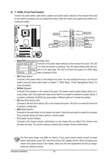
8) F_PANEL (Front Panel Header)<br />
Connect the power switch, reset switch, speaker and system status indicator on the chassis front panel<br />
to this header according to the pin assignments below. Note the positive and negative pins before connecting<br />
the cables.<br />
Speaker<br />
Power<br />
Switch<br />
Message/Power/<br />
Sleep LED<br />
The front panel design may differ by chassis. A front panel module mainly consists of power<br />
switch, reset switch, power LED, hard drive activity LED, speaker and etc. When connecting your<br />
chassis front panel module to this header, make sure the wire assignments and the pin assignments<br />
are matched correctly.<br />
Hardware Installation - 16 -<br />
20 19<br />
SPEAK-<br />
SPEAK+<br />
PW-<br />
PW+<br />
MSG-<br />
MSG+<br />
�������<br />
2<br />
1<br />
PWR-<br />
PWR+<br />
CI+<br />
CI-<br />
RES+<br />
RES-<br />
HD-<br />
HD+<br />
Power LED<br />
Chassis Intrusion<br />
Header<br />
Reset<br />
Switch<br />
Hard Drive<br />
Activity LED<br />
• MSG/PWR (Message/Power/Sleep LED):<br />
System Status LED Connects to the power status indicator on the chassis front panel. The LED<br />
S0 On is on when the system is operating. The LED keeps blinking when the sys-<br />
S1 Blinking tem is in S1 sleep state. The LED is off when the system is in S3/S4 sleep<br />
S3/S4/S5 Off<br />
state or powered off (S5).<br />
• PW (Power Switch):<br />
Connects to the power switch on the chassis front panel. You may configure the way to turn off your<br />
system using the power switch (refer to Chapter 2, "BIOS Setup," "Power Management Setup," for<br />
more information).<br />
• SPEAK (Speaker):<br />
Connects to the speaker on the chassis front panel. The system reports system startup status by issuing<br />
a beep code. One single short beep will be heard if no problem is detected at system startup. If<br />
a problem is detected, the BIOS may issue beeps in different patterns to indicate the problem.<br />
• HD (Hard Drive Activity LED)<br />
Connects to the hard drive activity LED on the chassis front panel. The LED is on when the hard drive<br />
is reading or writing data.<br />
• RES (Reset Switch):<br />
Connects to the reset switch on the chassis front panel. Press the reset switch to restart the computer<br />
if the computer freezes and fails to perform a normal restart.<br />
• CI (Chassis Intrusion Header):<br />
Connects to the chassis intrusion switch/sensor on the chassis that can detect if the chassis cover<br />
has been removed. This function requires a chassis with a chassis intrusion switch/sensor.