GA-K8VM800M / GA-K8VM800M-RH - visit site - Gigabyte
GA-K8VM800M / GA-K8VM800M-RH - visit site - Gigabyte
GA-K8VM800M / GA-K8VM800M-RH - visit site - Gigabyte

You also want an ePaper? Increase the reach of your titles
YUMPU automatically turns print PDFs into web optimized ePapers that Google loves.
<strong>GA</strong>-<strong>K8VM800M</strong> /<br />
<strong>GA</strong>-<strong>K8VM800M</strong>-<strong>RH</strong><br />
AMD Socket 754 Processor Motherboard<br />
User's Manual<br />
Rev. 2004<br />
12ME-<strong>K8VM800M</strong>-2004R<br />
* The WEEE marking on the product indicates this product must not be disposed of with user's other household waste<br />
and must be handed over to a designated collection point for the recycling of waste electrical and electronic equipment!!<br />
* The WEEE marking applies only in European Union's member states.
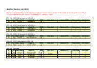
Aug. 8, 2005<br />
Aug. 8, 2005<br />
<strong>GA</strong>-<strong>K8VM800M</strong><br />
Motherboard<br />
Motherboard<br />
<strong>GA</strong>-<strong>K8VM800M</strong>
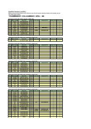
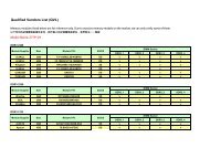
Jun. 21, 2006<br />
Jun. 21, 2006<br />
<strong>GA</strong>-<strong>K8VM800M</strong>-<strong>RH</strong><br />
Motherboard<br />
Motherboard<br />
<strong>GA</strong>-<strong>K8VM800M</strong>-<strong>RH</strong>
Copyright<br />
© 2006 GI<strong>GA</strong>-BYTE TECHNOLOGY CO., LTD. All rights reserved.<br />
The trademarks mentioned in the manual are legally registered to their respective companies.<br />
Notice<br />
The written content provided with this product is the property of <strong>Gigabyte</strong>.<br />
No part of this manual may be reproduced, copied, translated, or transmitted in any form or by any<br />
means without <strong>Gigabyte</strong>'s prior written permission. Specifications and features are subject to<br />
change without prior notice.<br />
Product Manual Classification<br />
In order to assist in the use of this product, <strong>Gigabyte</strong> has categorized the user manual in the<br />
following:<br />
� For detailed product information and specifications, please carefully read the<br />
"Product User Manual".<br />
� For detailed information related to <strong>Gigabyte</strong>'s unique features, please go to "Technology<br />
Guide" section on <strong>Gigabyte</strong>'s web<strong>site</strong> to read or download the information you need.<br />
For more product details, please click onto <strong>Gigabyte</strong>'s web<strong>site</strong> at www.gigabyte.com.tw
Table of Contents<br />
<strong>GA</strong>-<strong>K8VM800M</strong>(-<strong>RH</strong>) Motherboard Layout.................................................................... 7<br />
Block Diagram ................................................................................................................ 8<br />
Chapter 1 Hardware Installation .................................................................................... 9<br />
1-1 Considerations Prior to Installation .................................................................... 9<br />
1-2 Feature Summary .......................................................................................... 10<br />
1-3 Installation of the CPU and Heatsink .............................................................. 12<br />
1-3-1 Installation of the CPU ......................................................................................... 12<br />
1-3-2 Installation of the Heatsink .................................................................................. 13<br />
1-4 Installation of Memory .................................................................................... 14<br />
1-5 Installation of Expansion Cards ...................................................................... 15<br />
1-6 I/O Back Panel Introduction ........................................................................... 16<br />
1-7 Connectors Introduction .................................................................................. 17<br />
Chapter 2 BIOS Setup................................................................................................ 27<br />
The Main Menu (For example: BIOS Ver. : D1) ....................................................... 28<br />
2-1 Standard CMOS Features ............................................................................. 30<br />
2-2 Advanced BIOS Features .............................................................................. 32<br />
2-3 Integrated Peripherals ..................................................................................... 33<br />
2-4 Power Management Setup ............................................................................. 36<br />
2-5 PnP/PCI Configurations ................................................................................. 38<br />
2-6 PC Health Status ........................................................................................... 39<br />
2-7 Frequency / Voltage Control ........................................................................... 40<br />
2-8 Load Fail-Safe Defaults ................................................................................... 41<br />
2-9 Load Optimized Defaults ................................................................................. 41<br />
2-10 Set Supervisor/User Password ..................................................................... 42<br />
2-11 Save & Exit Setup ......................................................................................... 43<br />
2-12 Exit Without Saving ....................................................................................... 43<br />
- 5 -
Chapter 3 Drivers Installation ...................................................................................... 45<br />
3-1 Install Chipset Drivers .................................................................................... 45<br />
3-2 Software Application ....................................................................................... 46<br />
3-3 Software Information ....................................................................................... 46<br />
3-4 Hardware Information ..................................................................................... 47<br />
3-5 Contact Us ..................................................................................................... 47<br />
Chapter 4 Appendix ................................................................................................... 49<br />
4-1 Unique Software Utilities ................................................................................ 49<br />
4-1-1 EasyTune 5 Introduction ..................................................................................... 50<br />
4-1-2 Xpress Recovery Introduction ........................................................................... 51<br />
4-1-3 Flash BIOS Method Introduction ........................................................................ 54<br />
4-1-4 Serial ATA BIOS Setting Utility Introduction ...................................................... 63<br />
4-1-5 2 / 4 / 6 Channel Audio Function Introduction ................................................. 70<br />
4-2 Troubleshooting ............................................................................................... 74<br />
- 6 -
<strong>GA</strong>-<strong>K8VM800M</strong>(-<strong>RH</strong>) Motherboard Layout<br />
MS/KB<br />
COMA<br />
V<strong>GA</strong><br />
R_USB<br />
USB<br />
LPT<br />
AUDIO<br />
CODEC<br />
LAN<br />
ATX_12V<br />
IT8705<br />
COMB<br />
Socket 754<br />
BIOS PCI1<br />
VIA 6103L<br />
F_AUDIO<br />
CD_IN<br />
SPDIF_IO<br />
IR<br />
VIA K8M800<br />
F_USB1<br />
PCI2<br />
- 7 -<br />
CPU_FAN<br />
<strong>GA</strong>-<strong>K8VM800M</strong>(-<strong>RH</strong>)<br />
AGP<br />
F_USB2<br />
DDR1<br />
DDR2<br />
ATX<br />
VIA VT8237R /<br />
VT8237R+<br />
PCI3 BAT<br />
PWR_LED<br />
FDD<br />
IDE2 IDE1<br />
SYS_FAN<br />
SATA1<br />
SATA0<br />
F_PANEL<br />
CLR_CMOS
Block Diagram<br />
AGPCLK<br />
(66MHz)<br />
3 PCI<br />
PCICLK<br />
(33MHz)<br />
AGP<br />
4X/8X<br />
V<strong>GA</strong> Port<br />
LAN<br />
RJ45<br />
VIA 6103L<br />
2 Serial ATA<br />
Mll-Link<br />
AC97 Link<br />
Audio<br />
CODEC<br />
MIC<br />
LINE-IN<br />
LINE-OUT<br />
AMD<br />
Althlon TM 64<br />
processor (K8)<br />
VIA K8M800<br />
VIA VT8237R /<br />
VT8237R+<br />
8 USB<br />
Ports<br />
- 8 -<br />
H.T. Bus 800MHz<br />
LPC BUS<br />
ATA33/66/100/133<br />
IDE Channels<br />
CPUCLK+/- (200MHz)<br />
DDR RAM<br />
400/333/266/200MHz<br />
66 MHz<br />
14.318 MHz<br />
66 MHz<br />
33 MHz<br />
14.318 MHz<br />
BIOS<br />
IT8705<br />
24<br />
MHz<br />
33 MHz<br />
IR<br />
Floppy<br />
LPT Port<br />
PS/2 KB/Mouse<br />
2 COM<br />
Ports
Chapter 1Hardware Installation<br />
1-1 Considerations Prior to Installation<br />
Preparing Your Computer<br />
The motherboard contains numerous delicate electronic circuits and components which can<br />
become damaged as a result of electrostatic discharge (ESD). Thus, prior to installation, please<br />
follow the instructions below:<br />
1. Please turn off the computer and unplug its power cord.<br />
2. When handling the motherboard, avoid touching any metal leads or connectors.<br />
3. It is best to wear an electrostatic discharge (ESD) cuff when handling electronic components<br />
(CPU, RAM).<br />
4. Prior to installing the electronic components, please have these items on top of an antistatic<br />
pad or within a electrostatic shielding container.<br />
5. Please verify that the power supply is switched off before unplugging the power supply<br />
connector from the motherboard.<br />
Installation Notices<br />
1. Prior to installation, please do not remove the stickers on the motherboard. These stickers<br />
are required for warranty validation.<br />
2. Prior to the installation of the motherboard or any hardware, please first carefully read the<br />
information in the provided manual.<br />
3. Before using the product, please verify that all cables and power connectors are connected.<br />
4. To prevent damage to the motherboard, please do not allow screws to come in contact with<br />
the motherboard circuit or its components.<br />
5. Please make sure there are no leftover screws or metal components placed on the motherboard<br />
or within the computer casing.<br />
6. Please do not place the computer system on an uneven surface.<br />
7. Turning on the computer power during the installation process can lead to damage to system<br />
components as well as physical harm to the user.<br />
8. If you are uncertain about any installation steps or have a problem related to the use of the<br />
product, please consult a certified computer technician.<br />
Instances of Non-Warranty<br />
1. Damage due to natural disaster, accident or human cause.<br />
2. Damage as a result of violating the conditions recommended in the user manual.<br />
3. Damage due to improper installation.<br />
4. Damage due to use of uncertified components.<br />
5. Damage due to use exceeding the permitted parameters.<br />
6. Product determined to be an unofficial <strong>Gigabyte</strong> product.<br />
- 9 -<br />
Hardware Installation<br />
English
English<br />
1-2 Feature Summary<br />
CPU � Socket 754 for AMD Athlon TM 64 processor (K8)<br />
� 1600MH/z system bus<br />
� Supports core frequencies in excess of 3000+ and faster<br />
Chipset � Northbridge: VIA K8M800<br />
� Southbridge: VIA VT8237R / VT8237R+<br />
Memory � 2 DDR DIMM memory slots (supports up to 2GB memory)<br />
� Supports DDR 400 (Note 1) /333/266/200 DIMM<br />
� Supports 2.5V DDR DIMM<br />
Slots � 1 AGP slot<br />
� 3 PCI slots<br />
IDE Connections � 2 IDE connection (UDMA 33/ATA 66/ATA 100/ATA 133), allows connection of<br />
4 IDE devices<br />
FDD Connections � 1 FDD connection, allows connection of 2 FDD devices<br />
Onboard SATA � 2 Serial ATA connections (Note2)<br />
Peripherals � 1 parallel port supporting Normal/EPP/ECP mode<br />
� 1 serial port (COMA), 1 V<strong>GA</strong> port, onboard COMB connection<br />
� 8 USB 2.0/1.1 ports (rear x 4, front x 4 via cable)<br />
� 1 front audio connector<br />
� 1 IR connector<br />
� 1 PS/2 keyboard port<br />
� 1 PS/2 mouse port<br />
On-Board V<strong>GA</strong> � Build in VIA K8M800 Chipset<br />
Onboard LAN � Onboard VIA 6103L chip (10/100 Mbit)<br />
� 1 RJ 45 port<br />
Onboard Audio � Realtek ALC655 CODEC<br />
� Supports Line In ; Line Out ; MIC In<br />
� Supports 2 / 4 / 6 channel audio<br />
� SPDIF In/Out connection<br />
� CD In connection<br />
I/O Control � IT8705<br />
(Note 1) Because of CPU limitations, if you want to install DDR400 memory modules in your system, please install either<br />
one double-sided or two single-sided DDR400 memory modules. The DDR400 speed will drop down to DDR333 if<br />
you install two double-sided DDR400 memory modules.<br />
(Note 2) It is recommended to use SATA (1.5Gb/s) hard disks.<br />
<strong>GA</strong>-<strong>K8VM800M</strong>(-<strong>RH</strong>) Motherboard - 10 -
On-Board SATA RAID � Built in VIA VT8237R / VT8237R+<br />
� Supports Disk striping (RAID0) or DISK Mirroring (RAID1)<br />
� Supports UDMA up to 150 MB/sec<br />
� Up to 2 SATA Device<br />
Hardware Monitor � System voltage detection<br />
� CPU temperature detection<br />
� CPU / System fan speed detection<br />
� CPU fan failure warning<br />
BIOS � Use of licensed AWARD BIOS<br />
� Supports Q-Flash<br />
Additional Features � Supports @BIOS<br />
� (Note 3)<br />
Supports EasyTune<br />
Overclocking � Over Clock (CPU) by BIOS<br />
� Over Voltage (CPU/AGP) by BIOS<br />
Form Factor � Micro ATX form factor; 22.0cm x 24.4cm<br />
(Note 3) EasyTune functions may vary depending on different motherboards.<br />
- 11 -<br />
Hardware Installation<br />
English
English<br />
1-3 Installation of the CPU and Heatsink<br />
Before installing the CPU, please comply with the following conditions:<br />
1. Please make sure that the motherboard supports the CPU.<br />
2. Please take note of the one indented corner of the CPU. If you install the CPU in the wrong<br />
direction, the CPU will not insert properly. If this occurs, please change the insert direction<br />
of the CPU.<br />
3. Please add an even layer of heat sink paste between the CPU and heatsink.<br />
4. Please make sure the heatsink is installed on the CPU prior to system use, otherwise<br />
overheating and permanent damage of the CPU may occur.<br />
5. Please set the CPU host frequency in accordance with the processor specifications. It is not<br />
recommended that the system bus frequency be set beyond hardware specifications since it<br />
does not meet the required standards for the peripherals. If you wish to set the frequency<br />
beyond the proper specifications, please do so according to your hardware specifications<br />
including the CPU, graphics card, memory, hard drive, etc.<br />
1-3-1 Installation of the CPU<br />
Check the processor pins to see that none are bent. Move the socket lever to the unlocked position as shown<br />
in Figure 1.(90 o to the plane of the motherboard) prior to inserting the processor. The pin 1 location is<br />
designated on the processor by a copper triangle that matches up to a triangle on the socket as shown in<br />
Figure 2. Align the processor to the socket and gently lower it into place. Do not force the processor into the<br />
socket.<br />
Socket lever<br />
Fig.1<br />
Position lever at a 90 degree angle.<br />
<strong>GA</strong>-<strong>K8VM800M</strong>(-<strong>RH</strong>) Motherboard - 12 -<br />
Fig.2<br />
Pin 1 location on the socket and processor.<br />
Gently place the CPU into position making sure that the CPU pins fit<br />
perfectly into their holes. Once the CPU is positioned into its socket,<br />
place one finger down on the middle of the CPU and gently press the<br />
metal lever back into its original position.<br />
Please use extra care when installing the CPU. The CPU will not fit if positioned incorrectly.<br />
Rather than applying force, please change the positioning of the CPU.
1-3-2 Installation of the Heatsink<br />
Fig.1<br />
Before installing the heat sink, please first add an even layer of heat sink<br />
paste on the surface of the CPU. Install all the heat sink components (Please<br />
refer to the heat sink manual for detailed installation instructions).<br />
Fig.2<br />
Please connect the heat sink power connector to the CPU_FAN connector<br />
located on the motherboard so that the heat sink can properly function to<br />
prevent CPU overheating.<br />
The heat sink may adhere to the CPU as a result of hardening of the heat sink paste. To prevent<br />
such an occurrence, it is suggested that either thermal tape rather than heat sink paste be used for<br />
heat dissipation or using extreme care when removing the heat sink.<br />
- 13 -<br />
Hardware Installation<br />
English
English<br />
1-4 Installation of Memory<br />
Before installing the memory modules, please comply with the following conditions:<br />
1. Please make sure that the memory used is supported by the motherboard. It is<br />
recommended that memory of similar capacity, specifications and brand be used.<br />
2. Before installing or removing memory modules, please make sure that the computer power<br />
is switched off to prevent hardware damage.<br />
3. Memory modules have a foolproof insertion design. A memory module can be installed in<br />
only one direction. If you are unable to insert the module, please switch the direction.<br />
The motherboard supports DDR memory modules, whereby BIOS will automatically detect memory capacity<br />
and specifications. Memory modules are designed so that they can be inserted only in one direction. The<br />
memory capacity used can differ with each slot.<br />
<strong>GA</strong>-<strong>K8VM800M</strong>(-<strong>RH</strong>) Motherboard - 14 -<br />
Notch<br />
DDR<br />
Fig.1<br />
The DIMM socket has a notch, so the DIMM memory module can<br />
only fit in one direction. Insert the DIMM memory module vertically<br />
into the DIMM socket. Then push it down.<br />
Fig.2<br />
Close the plastic clip at both edges of the DIMM sockets to lock the<br />
DIMM module.<br />
Reverse the installation steps when you wish to remove the DIMM<br />
module.
1-5 Installation of Expansion Cards<br />
You can install your expansion card by following the steps outlined below:<br />
1. Read the related expansion card's instruction document before install the expansion card into the<br />
computer.<br />
2. Remove your computer's chassis cover, screws and slot bracket from the computer.<br />
3. Press the expansion card firmly into expansion slot in motherboard.<br />
4. Be sure the metal contacts on the card are indeed seated in the slot.<br />
5. Replace the screw to secure the slot bracket of the expansion card.<br />
6. Replace your computer's chassis cover.<br />
7. Power on the computer, if necessary, setup BIOS utility of expansion card from BIOS.<br />
8. Install related driver from the operating system.<br />
Installing a AGP expansion card:<br />
- 15 -<br />
Please carefully pull out the small whitedrawable<br />
bar at the end of the AGP slot<br />
when you try to install/uninstall the V<strong>GA</strong><br />
card. Please align the V<strong>GA</strong> card to the<br />
onboard AGP slot and press firmly down on<br />
the slot. Make sure your V<strong>GA</strong> card is locked<br />
by the small white-drawable bar.<br />
Hardware Installation<br />
English
English<br />
1-6 I/O Back Panel Introduction<br />
PS/2 Keyboard and PS/2 Mouse Connector<br />
To install a PS/2 port keyboard and mouse, plug the mouse to the upper port (green) and the keyboard to the<br />
lower port (purple).<br />
USB port<br />
Before you connect your device(s) into USB connector(s), please make sure your device(s) such as<br />
USB keyboard, mouse, scanner, zip, speaker...etc. have a standard USB interface. Also make sure<br />
your OS supports USB controller. If your OS does not support USB controller, please contact OS<br />
vendor for possible patch or driver upgrade. For more information please contact your OS or device(s)<br />
vendors.<br />
Parallel Port<br />
The parallel port allows connection of a printer, scanner and other peripheral devices.<br />
COM A (Serial Port)<br />
Connects to serial-based mouse or data processing devices.<br />
V<strong>GA</strong> Port<br />
Monitor can be connected to V<strong>GA</strong> port.<br />
LAN Port<br />
The provided Internet connection is fast Ethernet, providing data transfer speeds of 10/100Mbps.<br />
Line In<br />
Devices like CD-ROM, walkman etc. can be connected to Line In jack.<br />
Line Out (Front Speaker Out)<br />
Connect the stereo speakers, earphone or front surround channels to this connector.<br />
MIC In<br />
Microphone can be connected to MIC In jack.<br />
You can use audio software to configure 2-/4-/6- channel audio functioning.<br />
<strong>GA</strong>-<strong>K8VM800M</strong>(-<strong>RH</strong>) Motherboard - 16 -
1-7 Connectors Introduction<br />
1) ATX_12V<br />
2) ATX (Power Connector)<br />
3) CPU_FAN<br />
4) SYS_FAN<br />
5) FDD<br />
6) IDE1 / IDE2<br />
7) SATA0 / SATA1<br />
8) F_PANEL<br />
1<br />
10<br />
14<br />
11<br />
9) PWR_LED<br />
12<br />
15<br />
- 17 -<br />
3<br />
13 17<br />
10) F_AUDO<br />
11) CD_IN<br />
12) SPDIF_IO<br />
13) F_USB1 / F_USB2<br />
14) IR<br />
15) COMB<br />
16) CLR_CMOS<br />
17) BAT<br />
2<br />
9<br />
5<br />
6<br />
4<br />
7<br />
8<br />
16<br />
Hardware Installation<br />
English
English<br />
1/2) ATX_12V / ATX (Power Connector)<br />
With the use of the power connector, the power supply can supply enough stable power to all the<br />
components on the motherboard. Before connecting the power connector, please make sure that all<br />
components and devices are properly installed. Align the power connector with its proper location on<br />
the motherboard and connect tightly.<br />
The ATX_12V power connector mainly supplies power to the CPU. If the ATX_12V power<br />
connector is not connected, the system will not start.<br />
Caution!<br />
Please use a power supply that is able to handle the system voltage requirements. It is<br />
recommended that a power supply that can withstand high power consumption be used (300W or<br />
greater). If a power supply is used that does not provide the required power, the result can lead to an<br />
unstable system or a system that is unable to start.<br />
<strong>GA</strong>-<strong>K8VM800M</strong>(-<strong>RH</strong>) Motherboard - 18 -<br />
11<br />
20<br />
4 2 Pin No. Definition<br />
3<br />
1<br />
1<br />
10<br />
1 GND<br />
2 GND<br />
3 +12V<br />
4 +12V<br />
Pin No. Definition<br />
1 3.3V<br />
2 3.3V<br />
3 GND<br />
4 VCC<br />
5 GND<br />
6 VCC<br />
7 GND<br />
8 Power Good<br />
9 5V SB (stand by +5V)<br />
10 +12V<br />
11 3.3V<br />
12 -12V<br />
13 GND<br />
14 PS_ON(soft on/off)<br />
15 GND<br />
16 GND<br />
17 GND<br />
18 -5V<br />
19 +5V<br />
20 +5V
3/4) CPU_FAN / SYS_FAN (Cooler Fan Power Connector)<br />
The cooler fan power connector supplies a +12V power voltage via a 3-pin power connector and<br />
possesses a foolproof connection design.<br />
Most coolers are designed with color-coded power connector wires. A red power connector wire<br />
indicates a positive connection and requires a +12V power voltage. The black connector wire is the<br />
ground wire (GND).<br />
Please remember to connect the power to the cooler to prevent system overheating and failure.<br />
Caution!<br />
Please remember to connect the power to the CPU fan to prevent CPU overheating and failure.<br />
- 19 -<br />
CPU_FAN<br />
1<br />
1<br />
SYS_FAN<br />
Pin No. Definition<br />
1 GND<br />
2 +12V<br />
3 Sense<br />
5) FDD (FDD Connector)<br />
The FDD connector is used to connect the FDD cable while the other end of the cable connects to the<br />
FDD drive. The types of FDD drives supported are: 360KB, 720KB, 1.2MB, 1.44MB and 2.88MB.<br />
Before attaching the FDD cable, please take note of the foolproof groove in the FDD connector.<br />
34<br />
2<br />
33<br />
1<br />
Hardware Installation<br />
English
English<br />
6) IDE1 / IDE2 (IDE Connector)<br />
An IDE device connects to the computer via an IDE connector. One IDE connector can connect to one<br />
IDE cable, and the single IDE cable can then connect to two IDE devices (hard drive or optical drive). If<br />
you wish to connect two IDE devices, please set the jumper on one IDE device as Master and the other<br />
as Slave (for information on settings, please refer to the instructions located on the IDE device).<br />
Before attaching the IDE cable, please take note of the foolproof groove in the IDE connector.<br />
7) SATA0 / SATA1 (Serial ATA Connector)<br />
Serial ATA can provide up to150MB/s transfer rate. Please refer to the BIOS setting for the Serial ATA<br />
and install the proper driver in order to work properly.<br />
<strong>GA</strong>-<strong>K8VM800M</strong>(-<strong>RH</strong>) Motherboard - 20 -<br />
40<br />
2<br />
1 7<br />
IDE2 IDE1<br />
39<br />
Pin No. Definition<br />
1 GND<br />
2 TXP<br />
3 TXN<br />
4 GND<br />
5 RXN<br />
6 RXP<br />
7 GND<br />
1
8) F_PANEL (Front Panel Jumper)<br />
Please connect the power LED, PC speaker, reset switch and power switch etc of your chassis front<br />
panel to the F_PANEL connector according to the pin assignment below.<br />
Speaker Connector<br />
Power Switch<br />
Message LED/<br />
Power/<br />
Sleep LED<br />
HD (IDE Hard Disk Active LED) Pin 1: LED anode(+)<br />
Pin 2: LED cathode(-)<br />
SPEAK (Speaker Connector) Pin 1: Power<br />
Pin 2- Pin 3: NC<br />
Pin 4: Data(-)<br />
RES (Reset Switch) Open: Normal<br />
Close: Reset Hardware System<br />
PW (Power Switch) Open: Normal<br />
Close: Power On/Off<br />
MSG(Message LED/Power/Sleep LED) Pin 1: LED anode(+)<br />
Pin 2: LED cathode(-)<br />
NC NC<br />
- 21 -<br />
SPEAK-<br />
SPEAK+<br />
PW-<br />
PW+<br />
MSG-<br />
MSG+<br />
20 19<br />
2 1<br />
NC<br />
RES+<br />
RES-<br />
HD-<br />
HD+<br />
Reset Switch<br />
IDE Hard Disk<br />
Active LED<br />
Hardware Installation<br />
English
English<br />
9) PWR_LED<br />
The PWR_LED connector is connected with the system power indicator to indicate whether the<br />
system is on/off. It will blink when the system enters suspend mode.<br />
<strong>GA</strong>-<strong>K8VM800M</strong>(-<strong>RH</strong>) Motherboard - 22 -<br />
1<br />
Pin No. Definition<br />
1 MPD+<br />
2 MPD-<br />
3 MPD-<br />
10) F_AUDIO (Front Audio Panel Connector)<br />
If you want to use Front Audio connector, you must remove 5-6, 9-10 Jumper.<br />
In order to utilize the front audio header, your chassis must have front audio connector. Also please<br />
make sure the pin assignments for the cable are the same as the pin assignments for the front audio<br />
header. To find out if the chassis you are buying support front audio connector, please contact your<br />
dealer. Please note, you can have the alternative of using front audio connector or of using rear audio<br />
connector to play sound.<br />
9<br />
1<br />
2<br />
10<br />
Pin No. Definition<br />
1 MIC<br />
2 GND<br />
3 MIC_BIAS<br />
4 POWER<br />
5 FrontAudio(R)<br />
6 Rear Audio (R)/ Return R<br />
7 NC<br />
8 No Pin<br />
9 FrontAudio (L)<br />
10 Rear Audio (L)/ Return L
11) CD_IN (CD In Connector)<br />
Connect CD-ROM or DVD-ROM audio out to the connector.<br />
- 23 -<br />
1<br />
Pin No. Definition<br />
1 CD-L<br />
2 GND<br />
3 GND<br />
4 CD-R<br />
12) SPDIF_IO (SPDIF In/ Out)<br />
The SPDIF output is capable of providing digital audio to external speakers or compressed AC3 data to<br />
an external Dolby Digital Decoder. Use this feature only when your stereo system has digital input<br />
function. Use SPDIF IN feature only when your device has digital output function.<br />
Be careful with the polarity of the SPDIF_IO connector. Check the pin assignment carefully while you<br />
connect the SPDIF cable. Incorrect connection between the cable and connector will make the device<br />
unable to work or even damage it. For optional SPDIF cable, please contact your local dealer.<br />
6<br />
2<br />
5<br />
1<br />
Pin No. Definition<br />
1 Power<br />
2 No Pin<br />
3 SPDIF<br />
4 SPDIFI<br />
5 GND<br />
6 GND<br />
Hardware Installation<br />
English
English<br />
13) F_ USB1 / F_USB2 (Front USB Connector)<br />
Be careful with the polarity of the front USB connector. Check the pin assignment carefully while you<br />
connect the front USB cable, incorrect connection between the cable and connector will make the<br />
device unable to work or even damage it. For optional front USB cable, please contact your local dealer.<br />
<strong>GA</strong>-<strong>K8VM800M</strong>(-<strong>RH</strong>) Motherboard - 24 -<br />
2 10<br />
14) IR<br />
Be careful with the polarity of the IR connector while you connect the IR. Please contact your<br />
nearest dealer for optional IR device.<br />
1<br />
1<br />
9<br />
Pin No. Definition<br />
1 Power<br />
2 Power<br />
3 USB DX-<br />
4 USB Dy-<br />
5 USB DX+<br />
6 USB Dy+<br />
7 GND<br />
8 GND<br />
9 No Pin<br />
10 NC<br />
Pin No. Definition<br />
1 Power<br />
2 No Pin<br />
3 IR RX<br />
4 GND<br />
5 IR TX
15) COMB (COMB Connector)<br />
Be careful with the polarity of the COMB connector. Check the pin assignments while you connect<br />
the COMB cable. Please contact your nearest dealer for optional COMB cable.<br />
- 25 -<br />
Pin No. Definition<br />
1 NDCDB-<br />
2 NSINB<br />
3 NSOUTB<br />
4 NDTRB-<br />
5 GND<br />
6 NDSRB-<br />
7 NRTSB-<br />
8 NCTSB-<br />
9 NRIB-<br />
10 No Pin<br />
16) CLR_CMOS (Clear CMOS)<br />
You may clear the CMOS data to its default values by this jumper. To clear CMOS, temporarily<br />
short 1-2 pin. Default doesn't include the "Shunter" to prevent from improper use this jumper.<br />
2<br />
1<br />
1<br />
1<br />
10<br />
9<br />
Open: Normal<br />
Short: Clear CMOS<br />
Hardware Installation<br />
English
English<br />
17) BAT (Battery)<br />
<strong>GA</strong>-<strong>K8VM800M</strong>(-<strong>RH</strong>) Motherboard - 26 -<br />
Danger of explosion if battery is incorrectly replaced.<br />
Replace only with the same or equivalent type recommended<br />
by the manufacturer.<br />
Dispose of used batteries according to the manufacturer's<br />
instructions.<br />
If you want to erase CMOS...<br />
1. Turn off the computer and unplug the power cord.<br />
2. Gently take out the battery and put it aside for about one minute.<br />
(Or you can use a metal object to connect the positive and<br />
negative pins in the battery holder to makethem short for five<br />
seconds.)<br />
3. Re-install the battery.<br />
4. Plug the power cord in and turn on the computer.
Chapter 2 BIOS Setup<br />
BIOS (Basic Input and Output System) includes a CMOS SETUP utility which allows user to configure<br />
required settings or to activate certain system features.<br />
The CMOS SETUP saves the configuration in the CMOS SRAM of the motherboard.<br />
When the power is turned off, the battery on the motherboard supplies the necessary power to the CMOS<br />
SRAM.<br />
When the power is turned on, pushing the button during the BIOS POST (Power-On Self Test) will<br />
take you to the CMOS SETUP screen. You can enter the BIOS setup screen by pressing "Ctrl + F1".<br />
When setting up BIOS for the first time, it is recommended that you save the current BIOS to a disk in the<br />
event that BIOS needs to be reset to its original settings. If you wish to upgrade to a new BIOS, either<br />
GI<strong>GA</strong>BYTE's Q-Flash or @BIOS utility can be used.<br />
Q-Flash allows the user to quickly and easily update or backup BIOS without entering the operating system.<br />
@BIOS is a Windows-based utility that does not require users to boot to DOS before upgrading BIOS but<br />
directly download and update BIOS from the Internet.<br />
CONTROL KEYS<br />
< > < > < > < > Move to select item<br />
Select Item<br />
Main Menu - Quit and not save changes into CMOS Status Page Setup Menu<br />
and Option Page Setup Menu - Exit current page and return to Main Menu<br />
Increase the numeric value or make changes<br />
Decrease the numeric value or make changes<br />
General help, only for Status Page Setup Menu and Option Page Setup Menu<br />
Item Help<br />
Restore the previous CMOS value from CMOS, only for Option Page Setup Menu<br />
Load the fail-safe default CMOS value from BIOS default table<br />
Load the Optimized Defaults<br />
Q-Flash utility<br />
System Information<br />
Save all the CMOS changes, only for Main Menu<br />
Main Menu<br />
The on-line description of the highlighted setup function is displayed at the bottom of the screen.<br />
Status Page Setup Menu / Option Page Setup Menu<br />
Press to pop up a small help window that describes the appropriate keys to use and the possible<br />
selections for the highlighted item. To exit the Help Window press .<br />
- 27 -<br />
BIOS Setup<br />
English
English<br />
The BIOS Setup menus described in this chapter are for reference only and may differ from the<br />
exact settings for your motherboard.<br />
The Main Menu (For example: BIOS Ver. : D1)<br />
Once you enter Award BIOS CMOS Setup Utility, the Main Menu (as figure below) will appear on the screen.<br />
Use arrow keys to select among the items and press to accept or enter the sub-menu.<br />
� Standard CMOS Features<br />
� Advanced BIOS Features<br />
� Integrated Peripherals<br />
� Power Management Setup<br />
� PnP/PCI Configurations<br />
� PC Health Status<br />
� Frequency/Voltage Control<br />
CMOS Setup Utility-Copyright (C) 1984-2005 Award Software<br />
If you can't find the setting you want, please press "Ctrl+F1" to search the advanced option hidden.<br />
����� Standard CMOS Features<br />
This setup page includes all the items in standard compatible BIOS.<br />
����� Advanced BIOS Features<br />
This setup page includes all the items of Award special enhanced features.<br />
����� Integrated Peripherals<br />
This setup page includes all onboard peripherals.<br />
����� Power Management Setup<br />
This setup page includes all the items of Green function features.<br />
����� PnP/PCI Configuration<br />
This setup page includes all the configurations of PCI & PnP ISA resources.<br />
����� PC Health Status<br />
This setup page is the System auto detect Temperature, voltage, fan, speed.<br />
����� Frequency/Voltage Control<br />
This setup page is control CPU’s clock and frequency ratio.<br />
����� Load Fail-Safe Defaults<br />
Fail-Safe Defaults indicates the value of the system parameters which the system would be in safe<br />
configuration.<br />
<strong>GA</strong>-<strong>K8VM800M</strong>(-<strong>RH</strong>) Motherboard - 28 -<br />
Load Fail-Safe Defaults<br />
Load Optimized Defaults<br />
Set Supervisor Password<br />
Set User Password<br />
Save & Exit Setup<br />
Exit Without Saving<br />
ESC: Quit ����: Select Item<br />
F8: Q-Flash F10: Save & Exit Setup<br />
Time, Date, Hard Disk Type...
����� Load Optimized Defaults<br />
Optimized Defaults indicates the value of the system parameters which the system would be in best<br />
performance configuration.<br />
����� Set Supervisor Password<br />
Change, set, or disable password. It allows you to limit access to the system and Setup, or just to Setup.<br />
����� Set User Password<br />
Change, set, or disable password. It allows you to limit access to the system.<br />
����� Save & Exit Setup<br />
Save CMOS value settings to CMOS and exit setup.<br />
����� Exit Without Saving<br />
Abandon all CMOS value changes and exit setup.<br />
- 29 -<br />
BIOS Setup<br />
English
English<br />
2-1 Standard CMOS Features<br />
CMOS Setup Utility-Copyright (C) 1984-2005 Award Software<br />
Standard CMOS Features<br />
Date (mm:dd:yy) Wed, May 11 2005<br />
Time (hh:mm:ss) 10:40:9<br />
� IDE Channel 0 Master [None]<br />
� IDE Channel 0 Slave [None]<br />
� IDE Channel 1 Master [None]<br />
� IDE Channel 1 Slave [None]<br />
� IDE Channel 2 Master [None]<br />
� IDE Channel 3 Master [None]<br />
Drive A [1.44M, 3.5"]<br />
Drive B [None]<br />
Floppy 3 Mode Suport [Disabled]<br />
Holt On [All, But Keyboard]<br />
Base Memory 640K<br />
Extended Memory 127M<br />
Total Memory 128M<br />
����: Move Enter: Select +/-/PU/PD: Value F10: Save ESC: Exit F1: General Help<br />
F5: Previous Values F6: Fail-Safe Defaults F7: Optimized Defaults<br />
Date<br />
The date format is , , , .<br />
Week The week, from Sun to Sat, determined by the BIOS and is display only<br />
Month The month, Jan. Through Dec.<br />
Day The day, from 1 to 31 (or the maximum allowed in the month)<br />
Year The year, from 1999 through 2098<br />
Time<br />
The times format in . The time is calculated base on the 24-hour militarytime<br />
clock. For example, 1 p.m. is 13:00:00.<br />
IDE Channel 0/1 Master, Slave<br />
IDE HDD Auto-Detection Press "Enter" to select this option for automatic device detection.<br />
IDE Device Setup. You can use one of three methods:<br />
Auto Allows BIOS to automatically detect IDE devices during POST.(default)<br />
None Select this if no IDE devices are used and the system will skip the automatic<br />
detection step and allow for faster system start up.<br />
Manual User can manually input the correct settings<br />
Access Mode Use this to set the access mode for the hard drive. The four options are:<br />
CHS/LBA/Large/Auto(default:Auto)<br />
IDE Channel 2/3 Master<br />
IDE HDD Auto-Detection Press "Enter" to select this option for automatic device detection.<br />
Extended IDE Drive SATA devices setup. You can use one of two methods:<br />
Auto Allows BIOS to automatically detect SATA IDE devices during POST.<br />
(Default value)<br />
None Select this if no SATA IDE devices are used and the system will skip the<br />
automatic detection step and allow for faster system start up.<br />
Access Mode Use this to set the access mode for the hard drive. The two options are:<br />
Large/Auto(default:Auto)<br />
<strong>GA</strong>-<strong>K8VM800M</strong>(-<strong>RH</strong>) Motherboard - 30 -<br />
Item Help<br />
Menu Level�<br />
Change the day, month,<br />
year<br />
<br />
Sun. to Sat.<br />
<br />
Jan. to Dec.<br />
<br />
1 to 31 (or maximum<br />
allowed in the month)<br />
<br />
1999 to 2098
Capacity Capacity of currently installed hard disk.<br />
Hard drive information should be labeled on the outside drive casing. Enter the appropriate option<br />
based on this information.<br />
Cylinder Number of cylinders<br />
Head Number of heads<br />
Precomp Write precomp<br />
Landing Zone Landing zone<br />
Sector<br />
Drive A / Drive B<br />
Number of sectors<br />
The category identifies the types of floppy disk drive A or drive B that has been installed in the<br />
computer.<br />
None No floppy drive installed<br />
360K, 5.25" 5.25 inch PC-type standard drive; 360K byte capacity.<br />
1.2M, 5.25" 5.25 inch AT-type high-density drive; 1.2M byte capacity<br />
(3.5 inch when 3 Mode is Enabled).<br />
720K, 3.5" 3.5 inch double-sided drive; 720K byte capacity<br />
1.44M, 3.5" 3.5 inch double-sided drive; 1.44M byte capacity. (Default value)<br />
2.88M, 3.5" 3.5 inch double-sided drive; 2.88M byte capacity.<br />
Floppy 3 Mode Support (for Japan Area)<br />
Disabled Normal Floppy Drive. (Default value)<br />
Drive A Drive A is 3 mode Floppy Drive.<br />
Drive B Drive B is 3 mode Floppy Drive.<br />
Both<br />
Halt on<br />
Drive A & B are 3 mode Floppy Drives.<br />
The category determines whether the computer will stop if an error is detected during power up.<br />
No Errors The system boot will not stop for any error that may be detected and you<br />
will be prompted.<br />
All Errors Whenever the BIOS detects a non-fatal error the system will be stopped.<br />
All, But Keyboard The system boot will not stop for a keyboard error; it will stop for all other<br />
errors. (Default value)<br />
All, But Diskette The system boot will not stop for a disk error; it will stop for all other errors.<br />
All, But Disk/Key The system boot will not stop for a keyboard or disk error; it will stop for all<br />
other errors.<br />
Memory<br />
The category is display-only which is determined by POST (Power On Self Test) of the BIOS.<br />
Base Memory<br />
The POST of the BIOS will determine the amount of base (or conventional) memory installed<br />
in the system.<br />
The value of the base memory is typically 512K for systems with 512K memory installed on<br />
the motherboard, or 640K for systems with 640K or more memory installed on the motherboard.<br />
Extended Memory<br />
The BIOS determines how much extended memory is present during the POST.<br />
This is the amount of memory located above 1 MB in the CPU's memory address map.<br />
Total Memory<br />
This item displays the memory size that used.<br />
- 31 -<br />
BIOS Setup<br />
English
English<br />
2-2 Advanced BIOS Features<br />
CMOS Setup Utility-Copyright (C) 1984-2005 Award Software<br />
Advanced BIOS Features<br />
� Hard Disk Boot Priority [Press Enter]<br />
First Boot Device [Floppy]<br />
Second Boot Device [Hard Disk]<br />
Third Boot Device [CDROM]<br />
Password Check [Setup]<br />
����: Move Enter: Select +/-/PU/PD: Value F10: Save ESC: Exit F1: General Help<br />
F5: Previous Values F6: Fail-Safe Defaults F7: Optimized Defaults<br />
Hard Disk Boot Priority<br />
Select boot sequence for onboard(or add-on cards) SCSI, RAID, etc.<br />
Use < > or < > to select a device, then press to move it up, or to move it down the list. Press<br />
to exit this menu.<br />
First / Second / Third Boot Device<br />
Floppy Select your boot device priority by Floppy.<br />
LS120 Select your boot device priority by LS120.<br />
Hard Disk Select your boot device priority by Hard Disk.<br />
CDROM Select your boot device priority by CDROM.<br />
ZIP Select your boot device priority by ZIP.<br />
USB-FDD Select your boot device priority by USB-FDD.<br />
USB-ZIP Select your boot device priority by USB-ZIP.<br />
USB-CDROM Select your boot device priority by USB-CDROM.<br />
USB-HDD Select your boot device priority by USB-HDD.<br />
Legacy LAN Select your boot device priority by Legacy LAN.<br />
Disabled Disable this function.<br />
Password Check<br />
System The system can not boot and can not access to Setup page will be denied if the<br />
correct password is not entered at the prompt.<br />
Setup The system will boot, but access to Setup will be denied if the correct password is<br />
not entered at the prompt. (Default value)<br />
<strong>GA</strong>-<strong>K8VM800M</strong>(-<strong>RH</strong>) Motherboard - 32 -<br />
Item Help<br />
Menu Level�<br />
Select Hard Disk Boot<br />
Device Priority
2-3 Integrated Peripherals<br />
CMOS Setup Utility-Copyright (C) 1984-2005 Award Software<br />
Integrated Peripherals<br />
IDE DMA transfer access [Enabled]<br />
On-Chip IDE Channel 0 [Enabled]<br />
On-Chip IDE Channel 1 [Enabled]<br />
OnChip Serial ATA [Enabled]<br />
SATA Mode [RAID]<br />
AC97 Audio [Auto]<br />
VIA Onboard LAN [Enabled]<br />
USB 1.1 Controller [Enabled]<br />
USB 2.0 Controller [Enabled]<br />
USB Keyboard Support [Disabled]<br />
USB Mouse Support [Disabled]<br />
On-Chip LAN Boot ROM [Disabled]<br />
Onboard FDC Controller [Enabled]<br />
Onboard Serial Port 1 [3F8/IRQ4]<br />
Onboard Serial Port 2 [2F8/IRQ3]<br />
UART Mode Select [Normal]<br />
x UR2 Duplex Mode Half<br />
Onboard Parallel Port [378/IRQ7]<br />
Parallel Port Mode [SPP]<br />
����: Move Enter: Select +/-/PU/PD: Value F10: Save ESC: Exit F1: General Help<br />
F5: Previous Values F6: Fail-Safe Defaults F7: Optimized Defaults<br />
CMOS Setup Utility-Copyright (C) 1984-2005 Award Software<br />
Integrated Peripherals<br />
Midi Port Address [Disabled]<br />
x Midi Port IRQ 10<br />
IDE DMA transfer access<br />
Enabled Enable IDE DMA transfer access. (Default value)<br />
Disabled Disable this function.<br />
On-Chip IDE Channel0<br />
Enabled Enable onboard 1st channel IDE port. (Default value)<br />
Disabled Disable onboard 1st channel IDE port.<br />
On-Chip IDE Channel1<br />
Enabled Enable onboard 2nd channel IDE port. (Default value)<br />
Disabled Disable onboard 2nd channel IDE port.<br />
- 33 -<br />
Item Help<br />
Menu Level�<br />
Item Help<br />
Menu Level�<br />
����: Move Enter: Select +/-/PU/PD: Value F10: Save ESC: Exit F1: General Help<br />
F5: Previous Values F6: Fail-Safe Defaults F7: Optimized Defaults<br />
BIOS Setup<br />
English
English<br />
OnChip Serial ATA<br />
Enabled Enable VT8237R / VT8237R+ Serial ATA supported. (Default value)<br />
Disabled Disable VT8237R / VT8237R+ Serial ATA supported.<br />
SATA Mode<br />
RAID Set onboard SATA mode to RAID. (Default value)<br />
IDE Set onboard SATA mode to IDE.<br />
AC97 Audio<br />
Auto Enable onboard AC'97 audio function. (Default value)<br />
Disabled Disable this function.<br />
VIA Onboard LAN<br />
Enabled Enable VIA onboard LAN function. (Default value)<br />
Disabled Disable this function.<br />
USB 1.1 Controller<br />
Disabled Disable USB 1.1 controller.<br />
Enabled Enable USB 1.1 controller. (Default value)<br />
USB 2.0 Controller<br />
Disabled Disable USB 2.0 controller.<br />
Enabled Enable USB 2.0 controller. (Default value)<br />
USB Keyboard Support<br />
Enabled Enable USB keyboard support.<br />
Disabled Disable USB keyboard support. (Default value)<br />
USB Mouse Support<br />
Enabled Enable USB mouse support.<br />
Disabled Disable USB mouse support. (Default value)<br />
On-Chip LAN Boot ROM<br />
This function decide whether to invoke the boot ROM of the onboard LAN chip.<br />
PXE Set On-Chip LAN Boot ROM to PXE.<br />
RPL Set On-Chip LAN Boot ROM to RPL.<br />
Disabled Disable this function. (Default value)<br />
Onboard FDC Controller<br />
Enabled Enable onboard FDC Controller. (Default value)<br />
Disabled Disable onboard FDC Controller.<br />
Onboard Serial Port 1<br />
Auto BIOS will automatically setup the Serial port 1 address.<br />
3F8/IRQ4 Enable onboard Serial port 1 and address is 3F8/IRQ4. (Default value)<br />
2F8/IRQ3 Enable onboard Serial port 1 and address is 2F8/IRQ3.<br />
3E8/IRQ4 Enable onboard Serial port 1 and address is 3E8/IRQ4.<br />
2E8/IRQ3 Enable onboard Serial port 1 and address is 2E8/IRQ3.<br />
Disabled Disable onboard Serial port 1.<br />
<strong>GA</strong>-<strong>K8VM800M</strong>(-<strong>RH</strong>) Motherboard - 34 -
Onboard Serial Port 2<br />
Auto BIOS will automatically set up the Serial port 2 address.<br />
3F8/IRQ4 Enable onboard Serial port 2 and address is 3F8/IRQ4.<br />
2F8/IRQ3 Enable onboard Serial port 2 and address is 2F8/IRQ3. (Default value)<br />
3E8/IRQ4 Enable onboard Serial port 2 and address is 3E8/IRQ4.<br />
2E8/IRQ3 Enable onboard Serial port 2 and address is 2E8/IRQ3.<br />
Disabled Disable onboard Serial port 2.<br />
UART Mode Select<br />
This item allows you to determine which Infra Red(IR) function of Onboard I/O chip.<br />
Normal Set onboard I/O chip UART to Normal mode.(Default value)<br />
IrDA Set onboard I/O chip UART to IrDA mode.<br />
ASKIR Set onboard I/O chip UART to ASKIR mode.<br />
UR2 Duplex Mode<br />
This feature allows you to select IR mode.<br />
This function is available only when UART Mode Select is not set to Normal.<br />
Half IR Function Duplex Half. (Default value)<br />
Full IR Function Duplex Full.<br />
Onboard Parallel Port<br />
Disabled Disable onboard LPT port.<br />
378/IRQ7 Enable onboard LPT port and address is 378/IRQ7. (Default value)<br />
278/IRQ5 Enable onboard LPT port and address is 278/IRQ5.<br />
3BC/IRQ7 Enable onboard LPT port and address is 3BC/IRQ7.<br />
Parallel Port Mode<br />
SPP Using Parallel port as Standard Parallel Port. (Default value)<br />
EPP Using Parallel port as Enhanced Parallel Port.<br />
ECP Using Parallel port as Extended Capabilities Port.<br />
ECP+EPP Using Parallel port as ECP and EPP mode.<br />
Midi Port Address<br />
300 Set Midi Port Address to 300.<br />
330 Set Midi Port Address to 330<br />
Disabled Disable this function. (Default value)<br />
Midi Port IRQ<br />
5 Set Midi Port IRQ to 5.<br />
10 Set Midi Port IRQ to 10. (Default value)<br />
- 35 -<br />
BIOS Setup<br />
English
English<br />
2-4 Power Management Setup<br />
CMOS Setup Utility-Copyright (C) 1984-2005 Award Software<br />
Power Management Setup<br />
ACPI Suspend Type [S1(POS)]<br />
x USB Device Wake-Up From S3 Disabled<br />
Soft-Off by PWRBTN [Instant-Off]<br />
AC Back Function [Soft-Off]<br />
Keyboard Power On [Disabled]<br />
Mouse Power On [Disabled]<br />
PME Event Wake Up [Enabled]<br />
Modem Ring Resume [Enabled]<br />
Resume by Alarm [Disabled]<br />
x Date (of Month) Alarm Everyday<br />
x Time (hh:mm:ss) Alarm 0 : 0 : 0<br />
����: Move Enter: Select +/-/PU/PD: Value F10: Save ESC: Exit F1: General Help<br />
F5: Previous Values F6: Fail-Safe Defaults F7: Optimized Defaults<br />
ACPI Suspend Type<br />
S1(POS) Set ACPI suspend type to S1/POS(Power On Suspend). (Default value)<br />
S3(STR) Set ACPI suspend type to S3/STR(Suspend To RAM).<br />
USB Device Wake-Up From S3<br />
Disabled Disable USB Device Wake-Up from S3. (Default value)<br />
Enabled Enable USB Device Wake-Up from S3.<br />
Soft-Off by PWRBTN<br />
Instant-Off Press power button then Power off instantly. (Default value)<br />
Delay 4 Sec. Press power button 4 sec. to Power off. Enter suspend if button is pressed<br />
less than 4 sec.<br />
AC BACK Function<br />
Memory When AC-power back to the system, the system will be back to the last state<br />
before AC-power is lost.<br />
Soft-Off When AC-power back to the system, the system will be in "Off" state.<br />
(Default value)<br />
Full-On When AC-power back to the system, the system always in "On" state.<br />
Keyboard Power On<br />
Password Enter from 1 to 8 characters to set the Keyboard Power On Password.<br />
Disabled Disabled this function. (Default value)<br />
Keyboard 98 If your keyboard have "POWER Key" button, you can press the key to power<br />
on the system.<br />
<strong>GA</strong>-<strong>K8VM800M</strong>(-<strong>RH</strong>) Motherboard - 36 -<br />
Item Help<br />
Menu Level�<br />
[S1]<br />
Set suspend type to<br />
Power On Suspend under<br />
ACPI OS<br />
[S3]<br />
Set suspend type to<br />
Suspend to RAM under<br />
ACPI OS
Mouse Power On<br />
Disabled Disabled this function. (Default value)<br />
Enabled Double click on PS/2 mouse left button to power on the system.<br />
PME Event Wake Up<br />
This feature requires an ATX power supply that provides at least 1A on the 5VSB lead.<br />
Disabled Disable this function.<br />
Enabled Enable PME as wake up event. (Default value)<br />
Modem Ring Resume<br />
An incoming call via modem can awake the system from any suspend state.<br />
Disabled Disable Modem Ring Resume function.<br />
Enabled Enable Modem Ring Resume function. (Default value)<br />
Resume by Alarm<br />
You can set "Resume by Alarm" item to enabled and key in Date/Time to power on system.<br />
Disabled Disable this function. (Default value)<br />
Enabled Enable alarm function to POWER ON system.<br />
If Resume by Alarm is Enabled.<br />
Date (of Month) Alarm : Everyday, 1~31<br />
Time (hh: mm: ss) Alarm: (0~23) : (0~59) : (0~59)<br />
- 37 -<br />
BIOS Setup<br />
English
English<br />
2-5 PnP/PCI Configurations<br />
CMOS Setup Utility-Copyright (C) 1984-2005 Award Software<br />
PnP/PCI Configurations<br />
PCI 1 IRQ Assignment [Auto]<br />
PCI 2 IRQ Assignment [Auto]<br />
PCI 3 IRQ Assignment [Auto]<br />
����: Move Enter: Select +/-/PU/PD: Value F10: Save ESC: Exit F1: General Help<br />
F5: Previous Values F6: Fail-Safe Defaults F7: Optimized Defaults<br />
PCI 1 IRQ Assignment<br />
Auto Auto assign IRQ to PCI 1. (Default value)<br />
3,4,5,7,9,10,11,12,14,15 Set IRQ 3,4,5,7,9,10,11,12,14,15 to PCI 1.<br />
PCI 2 IRQ Assignment<br />
Auto Auto assign IRQ to PCI 2. (Default value)<br />
3,4,5,7,9,10,11,12,14,15 Set IRQ 3,4,5,7,9,10,11,12,14,15 to PCI 2.<br />
PCI 3 IRQ Assignment<br />
Auto Auto assign IRQ to PCI 3. (Default value)<br />
3,4,5,7,9,10,11,12,14,15 Set IRQ 3,4,5,7,9,10,11,12,14,15 to PCI 3.<br />
<strong>GA</strong>-<strong>K8VM800M</strong>(-<strong>RH</strong>) Motherboard - 38 -<br />
Item Help<br />
Menu Level�
2-6 PC Health Status<br />
Current Voltage(V) Vcore / DDR25V / +3.3V / +12V<br />
Detect system's voltage status automatically.<br />
Current CPU Temperature<br />
Detect CPU temperature automatically.<br />
CMOS Setup Utility-Copyright (C) 1984-2005 Award Software<br />
PC Health Status<br />
Vcore OK<br />
DDR25V OK<br />
+3.3V OK<br />
+12V OK<br />
Current CPU Temperature 35°C<br />
Current CPU FAN Speed 3125 RPM<br />
Current SYSTEM FAN Speed 0 RPM<br />
CPU FAN Fail Warning [Disabled]<br />
SYSTEM FAN Fail Warning [Disabled]<br />
Current CPU/SYSTEM FAN Speed (RPM)<br />
Detect CPU/SYSTEM fan speed status automatically.<br />
CPU FAN Fail Warning<br />
Disabled Disable CPU fan fail warning function. (Default value)<br />
Enabled Enable CPU fan fail warning function.<br />
SYSTEM FAN Fail Warning<br />
Disabled Disable SYSTEM fan fail warning function. (Default value)<br />
Enabled Enable SYSTEM fan fail warning function.<br />
- 39 -<br />
Item Help<br />
Menu Level�<br />
����: Move Enter: Select +/-/PU/PD: Value F10: Save ESC: Exit F1: General Help<br />
F5: Previous Values F6: Fail-Safe Defaults F7: Optimized Defaults<br />
BIOS Setup<br />
English
English<br />
2-7 Frequency / Voltage Control<br />
CMOS Setup Utility-Copyright (C) 1984-2005 Award Software<br />
Frequency/Voltage Control<br />
K8 CPU Clock Ratio [Default]<br />
CPU Host Clock Control [Disabled]<br />
x CPU Host Frequency 200<br />
PCI/AGP Frequency 33/66<br />
CPU OverVoltage Control [Auto]<br />
AGP OverVoltage Control [Audo]<br />
����: Move Enter: Select +/-/PU/PD: Value F10: Save ESC: Exit F1: General Help<br />
F5: Previous Values F6: Fail-Safe Defaults F7: Optimized Defaults<br />
Incorrect using these features may cause your system broken. For power end-user use only.<br />
K8 CPU Clock Ratio<br />
Default Set K8 CPU Clock Ratio to CPU factory default. (Default value)<br />
x4 800Mhz ~ x10 2000Mhz Set K8 CPU Clock Ratio from x4 800Mhz to x10 2000Mhz.<br />
CPU Host Clock Control<br />
Note: Please note that if your system is overclocked and cannot restart, please wait 20secs.<br />
for automatic system restart or clear the CMOS setup data and perform a safe restart.<br />
Disabled Disable CPU Host Clock Control.(Default value)<br />
Enabled Enable CPU Host Clock Control.<br />
CPU Host Frequency (Mhz)<br />
200MHz ~455MHz Set CPU Host Frequency from 200MHz to 455MHz.<br />
PCI /AGP Frequency(Mhz)<br />
The values depend on CPU Host Frequency(Mhz).<br />
CPU OverVoltage Control<br />
Auto BIOS will automatically detect CPU voltage. (Default value)<br />
+5% Set CPU OverVoltage Control to +5%.<br />
+7.5% Set CPU OverVoltage Control to +7.5%.<br />
+10% Set CPU OverVoltage Control to +10%.<br />
Incorrect using it may cause your system broken. For power End-User use only!<br />
AGP OverVoltage Control<br />
Auto BIOS will automatically detect AGP voltage. (Default value)<br />
+0.1V Set AGP OverVoltage Control to +0.1V.<br />
+0.2V Set AGP OverVoltage Control to +0.2V.<br />
Increase AGP voltage may get stable for Over_Clock. But it may damage to AGP Card when<br />
enable this feature.<br />
<strong>GA</strong>-<strong>K8VM800M</strong>(-<strong>RH</strong>) Motherboard - 40 -<br />
Item Help<br />
Menu Level�
2-8 Load Fail-Safe Defaults<br />
� Standard CMOS Features<br />
� Advanced BIOS Features<br />
� Integrated Peripherals<br />
� Power Management Setup<br />
� PnP/PCI Configurations<br />
� PC Health Status<br />
� Frequency/Voltage Control<br />
CMOS Setup Utility-Copyright (C) 1984-2005 Award Software<br />
Load Fail-Safe Defaults<br />
Load Optimized Defaults<br />
Set Supervisor Password<br />
Set User Password<br />
Load Fail-Safe Defaults Save (Y/N)? & Exit N Setup<br />
Exit Without Saving<br />
ESC: Quit ����: Select Item<br />
F8: Q-Flash F10: Save & Exit Setup<br />
Load Fail-Safe Defaults<br />
Fail-Safe defaults contain the most appropriate values of the system parameters that allow minimum system<br />
performance.<br />
2-9 Load Optimized Defaults<br />
� Standard CMOS Features<br />
� Advanced BIOS Features<br />
� Integrated Peripherals<br />
� Power Management Setup<br />
� PnP/PCI Configurations<br />
� PC Health Status<br />
� Frequency/Voltage Control<br />
CMOS Setup Utility-Copyright (C) 1984-2005 Award Software<br />
Load Fail-Safe Defaults<br />
Load Optimized Defaults<br />
Set Supervisor Password<br />
Set User Password<br />
Load Optimized Defaults Save (Y/N)? & Exit N<br />
Setup<br />
Exit Without Saving<br />
ESC: Quit ����: Select Item<br />
F8: Q-Flash F10: Save & Exit Setup<br />
Load Optimized Defaults<br />
Selecting this field loads the factory defaults for BIOS and Chipset Features which the system automatically<br />
detects.<br />
- 41 -<br />
BIOS Setup<br />
English
English<br />
2-10 Set Supervisor/User Password<br />
� Standard CMOS Features<br />
� Advanced BIOS Features<br />
� Integrated Peripherals<br />
� Power Management Setup<br />
� PnP/PCI Configurations Enter Password:<br />
� PC Health Status<br />
� Frequency/Voltage Control<br />
CMOS Setup Utility-Copyright (C) 1984-2005 Award Software<br />
ESC: Quit ����: Select Item<br />
F8: Q-Flash F10: Save & Exit Setup<br />
Change/Set/Disable Password<br />
When you select this function, the following message will appear at the center of the screen to assist you in<br />
creating a password.<br />
Type the password, up to eight characters, and press . You will be asked to confirm the password.<br />
Type the password again and press . You may also press to abort the selection and not enter<br />
a password.<br />
To disable password, just press when you are prompted to enter password. A message<br />
"PASSWORD DISABLED" will appear to confirm the password being disabled. Once the password is disabled,<br />
the system will boot and you can enter Setup freely.<br />
The BIOS Setup program allows you to specify two separate passwords:<br />
SUPERVISOR PASSWORD and a USER PASSWORD. When disabled, anyone may access all BIOS Setup<br />
program function. When enabled, the Supervisor password is required for entering the BIOS Setup program<br />
and having full configuration fields, the User password is required to access only basic items.<br />
If you select "System" at "Password Check" in Advance BIOS Features Menu, you will be prompted for the<br />
password every time the system is rebooted or any time you try to enter Setup Menu.<br />
If you select "Setup" at "Password Check" in Advance BIOS Features Menu, you will be prompted only when<br />
you try to enter Setup.<br />
<strong>GA</strong>-<strong>K8VM800M</strong>(-<strong>RH</strong>) Motherboard - 42 -<br />
Load Fail-Safe Defaults<br />
Load Optimized Defaults<br />
Set Supervisor Password<br />
Set User Password<br />
Save & Exit Setup<br />
Exit Without Saving
2-11 Save & Exit Setup<br />
� Standard CMOS Features<br />
� Advanced BIOS Features<br />
� Integrated Peripherals<br />
� Power Management Setup<br />
� PnP/PCI Configurations<br />
� PC Health Status<br />
� Frequency/Voltage Control<br />
Type "Y" will quit the Setup Utility and save the user setup value to RTC CMOS.<br />
Type "N" will return to Setup Utility.<br />
2-12 Exit Without Saving<br />
CMOS Setup Utility-Copyright (C) 1984-2005 Award Software<br />
Load Fail-Safe Defaults<br />
Load Optimized Defaults<br />
Set Supervisor Password<br />
Set User Password<br />
Save & Exit Setup<br />
Save to CMOS and EXIT Exit (Y/N)? Without Y Saving<br />
ESC: Quit ����: Select Item<br />
F8: Q-Flash F10: Save & Exit Setup<br />
Save Data to CMOS<br />
� Standard CMOS Features<br />
� Advanced BIOS Features<br />
� Integrated Peripherals<br />
� Power Management Setup<br />
� PnP/PCI Configurations<br />
� PC Health Status<br />
� Frequency/Voltage Control<br />
CMOS Setup Utility-Copyright (C) 1984-2005 Award Software<br />
Load Fail-Safe Defaults<br />
Load Optimized Defaults<br />
Set Supervisor Password<br />
Set User Password<br />
Quit Without Saving (Y/N)? Save & NExit<br />
Setup<br />
Exit Without Saving<br />
ESC: Quit ����: Select Item<br />
F8: Q-Flash F10: Save & Exit Setup<br />
Abandon all Data<br />
Type "Y" will quit the Setup Utility without saving to RTC CMOS.<br />
Type "N" will return to Setup Utility.<br />
- 43 -<br />
BIOS Setup<br />
English
English<br />
<strong>GA</strong>-<strong>K8VM800M</strong>(-<strong>RH</strong>) Motherboard - 44 -
Chapter 3Drivers Installation<br />
Pictures below are shown in Windows XP.<br />
Insert the driver CD-title that came with your motherboard into your CD-ROM drive, the driver<br />
CD-title will auto start and show the installation guide. If not, please double click the CD-ROM<br />
device icon in "My computer", and execute the Setup.exe.<br />
3-1 Install Chipset Drivers<br />
After insert the driver CD, "Xpress Install" will scan automatically the system and then list all the drivers that<br />
recommended to install. The "Xpress Install" uses the"Click and Go" technology to install the drivers<br />
automatically. Just select the drivers you want then click the "GO" button. The "Xpress Install" will execute<br />
the installation for you automatically.<br />
Some device drivers will restart your system automatically. After restarting your system the "Xpress<br />
Install" will continue to install other drivers.<br />
System will reboot automatically after install the drivers, afterward you can install others application.<br />
For USB2.0 driver support under Windows XP operating system, please use Windows Service<br />
Pack. After install Windows Service Pack, it will show a question mark "?" in "Universal Serial Bus<br />
controller" under "Device Manager". Please remove the question mark and restart the system<br />
(System will auto-detect the right USB2.0 driver).<br />
- 45 -<br />
Drivers Installation<br />
English
English<br />
3-2 Software Application<br />
This page displays all the tools that <strong>Gigabyte</strong> developed and some free software. You can click an item to<br />
install it.<br />
3-3 Software Information<br />
This page lists the contents of software and drivers in this CD-title.<br />
<strong>GA</strong>-<strong>K8VM800M</strong>(-<strong>RH</strong>) Motherboard - 46 -
3-4 Hardware Information<br />
This page lists all device you have for this motherboard.<br />
3-5 Contact Us<br />
Please see the last page for details.<br />
- 47 -<br />
Drivers Installation<br />
English
English<br />
<strong>GA</strong>-<strong>K8VM800M</strong>(-<strong>RH</strong>) Motherboard - 48 -
Chapter 4 Appendix<br />
4-1 Unique Software Utilities<br />
(Not all model support these Unique Software Utilities, please check your MB features.)<br />
U-PLUS D.P.S. (Universal Plus Dual Power System)<br />
The U-Plus Dual Power System (U-Plus DPS) is a revolutionary eight-phase power circuit<br />
built for ultimate system protection. Designed to withstand varying current levels and<br />
changes, the U-Plus D.P.S. provides an immensely durable and stable power circuit to the<br />
CPU for solid system stability. These characteristics make it the ideal companion with the<br />
latest L<strong>GA</strong>775 Intel ® Pentium ® 4 Processor as well as future Intel ® processors. As well, 4<br />
blue LED's are mounted on the U-Plus D.P.S. for intelligent indication of system loading.<br />
M.I.T. (Motherboard Intelligent Tweaker)<br />
Motherboard Intelligent Tweaker (M.I.T.) allows user to access and change BIOS feature<br />
settings with relative speed and ease. Through GI<strong>GA</strong>BYTE M.I.T. feature the user is no<br />
longer required to switch into different modes within BIOS setup in order to change system<br />
settings such as the CPU system bus, memory timings or to enabled <strong>Gigabyte</strong>'s unique<br />
C.I.A. 2 and M.I.B. 2 features. M.I.T.'s integration of all platform performance settings into<br />
a single mode now gives any user the ability to control and enhance their computer system<br />
to the desired level.<br />
C.I.A.2 (CPU Intelligent Accelerator 2)<br />
GI<strong>GA</strong>BYTE CPU Intelligent Accelerator 2(C.I.A. 2) is designed to automatically adjust CPU<br />
computing power to maximize system performance. When enabled, the program detects<br />
the current CPU loading and automatically accelerates the CPU computing performance to<br />
allow for a faster and smoother execution of programs. When the function is disabled, the<br />
CPU is returned to its initial status.<br />
M.I.B.2 (Memory Intelligent Booster 2)<br />
Built on the original M.I.B., the new Memory Intelligent Booster 2 (M.I.B. 2) is designed<br />
especially to maximize memory performance and boost memory bandwidth up to 10%.<br />
With added branded memory module information, users are able to optimize memory<br />
performance by selecting from a recommended memory module list.<br />
S.O.S. (System Overclock Saver)<br />
System Overclock Saver (S.O.S.) is a unique feature that eliminates system boot-up errors<br />
resulting from system over-enhancement by the user. With GI<strong>GA</strong>BYTE's proprietary<br />
S.O.S. feature, users no longer need to open up the PC chassis and short-circuit the "Clear<br />
CMOS" pins or the battery on the motherboard to reset the system back to factory default<br />
settings. Instead, S.O.S. automatically resets the overclocked system settings back to their<br />
factory defaults to provide a more user-friendly and reliable platform for users.<br />
Download Center<br />
Download Center allows users to quickly download and update their BIOS as well as the<br />
latest drivers for their system. Download Center automatically runs a system check of the<br />
user PC and provides the user with the current system information as well as displaying a<br />
detailed list of all new drivers with the option for download.<br />
C.O.M. (Corporate Online Management)<br />
A web-based system management tool that allows system hardware information such as<br />
CPU, memory, graphics card, etc. to be monitored and controlled via the Internet, C.O.M.<br />
allows corporate MIS engineers to easily maintain corporate computers such as providing<br />
the most up-to-date drivers and BIOS. (Do not use C.O.M. and @BIOS at the same time.)<br />
- 49 -<br />
Appendix<br />
English
English<br />
4-1-1 EasyTune 5 Introduction<br />
EasyTune 5 presents the most convenient Windows based system performance enhancement and<br />
manageability utility. Featuring several powerful yet easy to use tools such as 1) Overclocking for enhancing<br />
system performance, 2) C.I.A. and M.I.B. for special enhancement for CPU and Memory, 3) Smart-Fan<br />
control for managing fan speed control of both CPU cooling fan and North-Bridge Chipset cooling fan, 4) PC<br />
health for monitoring system status. (Note)<br />
User Interface Overview<br />
Button / Display Description<br />
1. Overclocking Enters the Overclocking setting page<br />
2. C.I.A./C.I.A.2 and M.I.B./M.I.B.2 Enters the C.I.A./2 and M.I.B./2 setting page<br />
3. Smart-Fan Enters the Smart-Fan setting page<br />
4. PC Health Enters the PC Health setting page<br />
5. GO Confirmation and Execution button<br />
6. "Easy Mode" & "Advance Mode" Toggles between Easy and Advance Mode<br />
7. Display screen Display panel of CPU frequency<br />
8. Function display LEDs Shows the current functions status<br />
9. GI<strong>GA</strong>BYTE Logo Log on to GI<strong>GA</strong>BYTE web<strong>site</strong><br />
10. Help button Display EasyTune TM 5 Help file<br />
11. Exit or Minimize button Quit or Minimize EasyTune TM 5 software<br />
(Note) EasyTune 5 functions may vary depending on different motherboards.<br />
<strong>GA</strong>-<strong>K8VM800M</strong>(-<strong>RH</strong>) Motherboard - 50 -
4-1-2 Xpress Recovery Introduction<br />
What is Xpress Recovery ?<br />
Xpress Recovery is a utility used to back up and restore an OS partition.<br />
If the hard drive is not working properly, the user can restore the drive to<br />
its original state.<br />
1. Supports FAT16, FAT32, and NTFS formats<br />
2. Must be connected to the IDE1 Master<br />
3. Allows installation of only one OS<br />
4. Must be used with an IDE hard disk supporting HPA<br />
5. The first partition must be set as the boot partition. When the boot partition is backed up,<br />
please do not alter its size.<br />
6. Xpress Recovery is recommended when using Ghost to return boot manager to NTFS<br />
format.<br />
How to use the Xpress Recovery<br />
1. Boot from CD-ROM (BMP Mode)<br />
Enter the BIOS menu, select "Advanced BIOS Feature" and set to boot from CD-ROM. Insert the<br />
provided driver CD into your CD drive, then save and exit the BIOS menu. Once the computer has<br />
restarted, the phrase "Boot from CD:" will appear at the bottom left-hand corner of the screen. When<br />
"Boot from CD:" appears, press any key to enter Xpress Recovery.<br />
Once you have completed this step, subsequent access to Xpress Recovery can also function by<br />
pressing the F9 key during computer power on.<br />
.<br />
.<br />
Verifying DMI Pool Data<br />
Boot from CD:<br />
Xpress Recovery V1.0 (C) Copy Right 2003. GI<strong>GA</strong>BYTE Technology CO. , Ltd.<br />
1. Execute Backup Utility<br />
2. Execute Restore Utility<br />
3. Remove Backup Image<br />
4. Set Password<br />
5. Exit and Restart<br />
- 51 -<br />
Boot from CD:<br />
Build 2011<br />
Appendix<br />
English
English<br />
2. Press F9 during powering on the computer. (Text Mode)<br />
Award Modular BIOS v6.00PG, An Energy Star Ally<br />
Copyright (C) 1984-2004, Award Software, Inc.<br />
Intel 865PE AGPSet BIOS for 8IPE1000MT F1<br />
Check System Health OK<br />
.<br />
.<br />
.<br />
Press DEL to enter SETUP / Q-Flash, F9 For Xpress Recovery<br />
08/16/2002-I845GE-6A69YG01C-00<br />
Xpress Recovery V1.0 (C) Copy Right 2003. GI<strong>GA</strong>BYTE Technology CO. , Ltd.<br />
1. Execute Backup Utility<br />
2. Execute Restore Utility<br />
3. Remove Backup Image<br />
4. Set Password<br />
5. Exit and Restart<br />
1. If you have already entered Xpress Recovery by booting from the CD-ROM, you can<br />
enter Xpress Recovery in the future by pressing the F9 key.<br />
2. System storage capacity as well as drive reading/writing speed will affect backup speed.<br />
3. It is recommended that Xpress Recovery be immediately installed after OS and all<br />
required driver and software installations are complete.<br />
<strong>GA</strong>-<strong>K8VM800M</strong>(-<strong>RH</strong>) Motherboard - 52 -<br />
F9 For Xpress Recovery
1. Execute Backup Utility:<br />
����� Press B to Backup your System or Esc to Exit<br />
The backup utility will automatically scan your system and back up data as a backup image in your hard<br />
drive.<br />
Not all systems support access to Xpress Recovery by pressing the F9 key during computer<br />
power on. If this is the case, please use the boot from CD-ROM method to enter Xpress<br />
Recovery.<br />
2. Execute Restore Utility:<br />
����� This program will recover your system to factory default.<br />
Press R to restore your system back to factory default or press Esc to exit<br />
Restores backup image to original state.<br />
3. Remove Backup Image:<br />
����� Remove backup image. Are you sure? (Y/N)<br />
Remove the backup image.<br />
4. Set Password:<br />
����� Please input a 4-16 character long password (a-z or 0-9) or press Esc to exit<br />
You can set a password to enter Xpress Recovery to protect your hard disk data. Once this is done,<br />
password input will be required to enter Xpress Recovery during the next as well as subsequent system<br />
restarts. If you wish to remove the need for password entry, please select "Set Password" and under<br />
"New Password/Confirm Password", make sure there is no entry and then press "Enter" to remove<br />
password requirement.<br />
5. Exit and Restart:<br />
Exit and restart your computer.<br />
- 53 -<br />
Appendix<br />
English
English<br />
4-1-3 Flash BIOS Method Introduction<br />
Method 1 : Q-Flash TM Utility<br />
Q-Flash TM is a BIOS flash utility embedded in Flash ROM. With this utility,<br />
users only have to stay in the BIOS menu when they want to update<br />
BIOS. Q-Flash?allows users to flash BIOS without any utility in DOS or<br />
Windows. Using Q-Flash TM indicating no more fooling around with any complicated instructions and<br />
operating system since it is in the BIOS menu.<br />
Please note that because updating BIOS has potential risk, please do it with caution!! We are<br />
sorry that <strong>Gigabyte</strong> Technology Co., Ltd is not responsible for damages of system because of<br />
incorrect manipulation of updating BIOS to avoid any claims from end-users.<br />
Before You Begin:<br />
Before you start updating BIOS with the Q-Flash TM utility, please follow the steps below first.<br />
1. Download the latest BIOS for your motherboard from <strong>Gigabyte</strong>'s web<strong>site</strong>.<br />
2. Extract the BIOS file downloaded and save the BIOS file (the one with model name.Fxx. For<br />
example, 8KNXPU.Fba) to a floppy disk.<br />
3. Reboot your PC and press Del to enter BIOS menu.<br />
The BIOS upgrading guides below are separated into two parts.<br />
If your motherboard has dual-BIOS, please refer to Part One.<br />
If your motherboard has single-BIOS, please refer to Part Two.<br />
Part One:<br />
Updating BIOS with Q-FlashTM Utility on Dual BIOS Motherboards.<br />
Some of <strong>Gigabyte</strong> motherboards are equipped with dual BIOS. In the BIOS menu of the motherboards<br />
supporting Q-Flash and Dual BIOS, the Q-Flash utility and Dual BIOS utility are combined in the same<br />
screen. This section only deals with how to use Q-Flash utility.<br />
In the following sections, we take <strong>GA</strong>-8KNXP Ultra as the example to guide you how to flash BIOS<br />
from an older version to the latest version. For example, from Fa3 to Fba.<br />
The BIOS file is Fa3<br />
before updating<br />
Award Modular BIOS v6.00PG, An Energy Star Ally<br />
Copyright (C) 1984-2003, Award Software, Inc.<br />
Intel i875P AGPset BIOS for 8KNXP Ultra Fa3<br />
Check System Health OK , VCore = 1.5250<br />
Main Processor : Intel Pentium(R) 4 1.6GHz (133x12)<br />
<br />
Memory Testing : 131072K OK<br />
Memory Frequency 266 MHz in Single Channel<br />
Primary Master : FUJITSU MPE3170AT ED-03-08<br />
Primary Slave : None<br />
Secondary Master : CREATIVEDVD-RM DVD1242E BC101<br />
Secondary Slave : None<br />
Press DEL to enter SETUP / Dual BIOS / Q-Flash / F9 For<br />
Xpress Recovery<br />
08/07/2003-i875P-6A79BG03C-00<br />
<strong>GA</strong>-<strong>K8VM800M</strong>(-<strong>RH</strong>) Motherboard - 54 -
Entering the Q-Flash TM utility:<br />
Step1: To use Q-Flash utility, you must press Del in the boot screen to enter BIOS menu.<br />
� Standard CMOS Features<br />
� Advanced BIOS Features<br />
� Integrated Peripherals<br />
� Power Management Setup<br />
� PnP/PCI Configurations<br />
� PC Health Status<br />
� MB Intelligent Tweaker(M.I.T.)<br />
CMOS Setup Utility-Copyright (C) 1984-2004 Award Software<br />
- 55 -<br />
Select Language<br />
Load Fail-Safe Defaults<br />
Load Optimized Defaults<br />
Set Supervisor Password<br />
Set User Password<br />
Save & Exit Setup<br />
Exit Without Saving<br />
ESC: Quit F3: Change Language<br />
F8: Dual BIOS/Q-Flash F10: Save & Exit Setup<br />
Time, Date, Hard Disk Type...<br />
Step 2: Press F8 button on your keyboard and then Y button to enter the Dual BIOS/Q-Flash utility.<br />
Exploring the Q-Flash TM / Dual BIOS utility screen<br />
The Q-Flash / Dual BIOS utility screen consists of the following key components.<br />
Task menu for<br />
Dual BIOS<br />
utility<br />
Task menu for<br />
Q-FlashTM utility<br />
Dual BIOS Utility<br />
Boot From......................................... Main Bios<br />
Main ROM Type/Size.............................SST 49LF003A 512K<br />
Backup ROM Type/Size.........................SST 49LF003A 512K<br />
Wide Range Protection Disable<br />
Boot From Main Bios<br />
Auto Recovery Enable<br />
Halt On Error Disable<br />
Copy Main ROM Data to Backup<br />
Load Default Settings<br />
Save Settings to CMOS<br />
Q-Flash Utility<br />
Load Main BIOS from Floppy<br />
Load Backup BIOS from Floppy<br />
Save Main BIOS to Floppy<br />
Save Backup BIOS to Floppy<br />
Enter : Run ��:Move ESC:Reset F10:Power Off<br />
Dual BIOS utility bar<br />
Q-FlashTM utility title<br />
bar<br />
Action bar<br />
Task menu for Dual BIOS utility:<br />
Contains the names of eight tasks and two item showing information about the BIOS ROM type. Blocking a<br />
task and pressing Enter key on your keyboard to enable execution of the task.<br />
Task menu for Q-Flash utility:<br />
Contains the names of four tasks. Blocking a task and pressing Enter key on your keyboard to enable execution<br />
of the task.<br />
Action bar:<br />
Contains the names of four actions needed to operate the Q-Flash/Dual BIOS utility. Pressing the buttons<br />
mentioned on your keyboards to perform these actions.<br />
Appendix<br />
English
English<br />
Using the Q-Flash TM utility:<br />
This section tells you how to update BIOS using the Q-Flash utility. As described in the "Before you begin"<br />
section above, you must prepare a floppy disk having the BIOS file for your motherboard and insert it to your<br />
computer. If you have already put the floppy disk into your system and have entered the Q-Flash utility,<br />
please follow the steps below to flash BIOS.<br />
Steps:<br />
1. Press arrow buttons on your keyboard to move the light bar to "Load Main BIOS from Floppy" item in<br />
the Q-Flash menu and press Enter button.<br />
Later, you will see a box pop up showing the BIOS files you previously downloaded to the floppy disk.<br />
If you want to save the current BIOS for backup purpose, you can begin Step 1 with "Save Main<br />
BIOS to Floppy" item.<br />
2. Move to the BIOS file you want to flash and press Enter.<br />
In this example, we only download one BIOS file to the floppy disk so only one BIOS file,<br />
8KNXPU.Fba, is listed.<br />
Please confirm again you have the correct BIOS file for your motherboard.<br />
Dual BIOS Utility<br />
Boot From......................................... Main Bios<br />
Main ROM Type/Size.............................SST 49LF003A 512K<br />
Backup ROM Type/Size.........................SST 49LF003A 512K<br />
Wide Range Protection Disable<br />
Boot From 1 file(s) Main foundBios<br />
8KNXPU.Fba 512K<br />
Auto Recovery Enable<br />
Halt On Error Disable<br />
Total size<br />
Copy<br />
: 1.39M<br />
Main ROM Data<br />
Free<br />
to Backup<br />
size : 911.50K<br />
F5 : Refresh<br />
Load Default Settings<br />
DEL : Delete<br />
Save Settings to CMOS<br />
Q-Flash Utility<br />
Load Main BIOS from Floppy<br />
Load Backup BIOS from Floppy<br />
Save Main BIOS to Floppy<br />
Save Backup BIOS to Floppy<br />
Enter : Run ��:Move ESC:Reset F10:Power Off<br />
After pressing Enter, you'll then see the progress of reading the BIOS file from the floppy disk.<br />
Dual BIOS Utility<br />
Boot From......................................... Main Bios<br />
Main ROM Type/Size.............................SST 49LF003A 512K<br />
Backup ROM Type/Size.........................SST 49LF003A 512K<br />
Wide Range Protection Disable<br />
Boot From Main Bios<br />
Reading BIOS file from floppy ...<br />
Auto Recovery Enable<br />
>>>>>>>>>>>>>>.....................<br />
Halt On Error Disable<br />
Copy Main ROM Data to Backup<br />
Don't Turn Off Power or Reset System<br />
Load Default Settings<br />
Save Settings to CMOS<br />
Q-Flash Utility<br />
Load Main BIOS from Floppy<br />
Load Backup BIOS from Floppy<br />
Save Main BIOS to Floppy<br />
Save Backup BIOS to Floppy<br />
Enter : Run ��:Move ESC:Reset F10:Power Off<br />
<strong>GA</strong>-<strong>K8VM800M</strong>(-<strong>RH</strong>) Motherboard - 56 -<br />
BIOS file in the floppy<br />
disk.<br />
Do not turn off power or<br />
reset your system at this<br />
stage!!<br />
After BIOS file is read, you'll see a confirmation dialog box asking you "Are you sure to update BIOS?"
3. Press Y button on your keyboard after you are sure to update BIOS.<br />
Then it will begin to update BIOS. The progress of updating BIOS will be displayed.<br />
Please do not take out the floppy disk when it begins flashing BIOS.<br />
4. Press any keys to return to the Q-Flash menu when the BIOS updating procedure is completed.<br />
Dual BIOS Utility<br />
Boot From......................................... Main Bios<br />
Main ROM Type/Size.............................SST 49LF003A 512K<br />
Backup ROM Type/Size.........................SST 49LF003A 512K<br />
Wide Range Protection<br />
Boot From<br />
Disable<br />
Main Bios<br />
You can repeat Step 1 to<br />
!! Auto Copy Recovery BIOS completed Enable - Pass !!<br />
4 to flash the backup<br />
Halt On Error Disable<br />
Copy Please Main press ROM any Data key to continue Backup<br />
Load Default Settings<br />
Save Settings to CMOS<br />
Q-Flash Utility<br />
Load Main BIOS from Floppy<br />
Load Backup BIOS from Floppy<br />
Save Main BIOS to Floppy<br />
Save Backup BIOS to Floppy<br />
Enter : Run ��:Move ESC:Reset F10:Power Off<br />
BIOS, too.<br />
5. Press Esc and then Y button to exit the Q-Flash utility. The computer will restart automatically after<br />
you exit Q-Flash.<br />
Dual BIOS Utility<br />
Boot From......................................... Main Bios<br />
Main ROM Type/Size.............................SST 49LF003A 512K<br />
Backup ROM Type/Size.........................SST 49LF003A 512K<br />
Wide Range Protection Disable<br />
Boot From Main Bios<br />
Auto Are Recovery you sure Enable to RESET ?<br />
Halt On Error Disable<br />
[Enter] Copy to Main continure ROM Data or [Esc] to Backup to abort...<br />
Load Default Settings<br />
Save Settings to CMOS<br />
Q-Flash Utility<br />
Load Main BIOS from Floppy<br />
Load Backup BIOS from Floppy<br />
Save Main BIOS to Floppy<br />
Save Backup BIOS to Floppy<br />
Enter : Run ��:Move ESC:Reset F10:Power Off<br />
After system reboots, you may find the BIOS version on your boot screen becomes the one you flashed.<br />
The BIOS file<br />
becomes Fab after<br />
updating.<br />
Award Modular BIOS v6.00PG, An Energy Star Ally<br />
Copyright (C) 1984-2003, Award Software, Inc.<br />
Intel i875P AGPset BIOS for 8KNXP Ultra Fba<br />
Check System Health OK , VCore = 1.5250<br />
Main Processor : Intel Pentium(R) 4 1.6GHz (133x12)<br />
<br />
Memory Testing : 131072K OK<br />
Memory Frequency 266 MHz in Single Channel<br />
Primary Master : FUJITSU MPE3170AT ED-03-08<br />
Primary Slave : None<br />
Secondary Master : CREATIVEDVD-RM DVD1242E BC101<br />
Secondary Slave : None<br />
Press DEL to enter SETUP / Dual BIOS / Q-Flash / F9 For<br />
Xpress Recovery<br />
09/23/2003-i875P-6A79BG03C-00<br />
- 57 -<br />
Appendix<br />
English
English<br />
6. Press Del to enter BIOS menu after system reboots. When you are in BIOS menu, move to<br />
Load Optimized Defaults item and press Enter to load BIOS Optimized Defaults. Normally the<br />
system redetects all devices after BIOS has been upgraded. Therefore, we highly recommend<br />
reloading the BIOS defaults after BIOS has been upgraded.<br />
CMOS Setup Utility-Copyright (C) 1984-2004 Award Software<br />
� Standard CMOS Features<br />
Select Language<br />
� Advanced BIOS Features<br />
Load Fail-Safe Defaults<br />
� Integrated Peripherals<br />
Load Optimized Defaults<br />
� Power Management Setup<br />
Set Supervisor Password<br />
� PnP/PCI Configurations<br />
Load Optimized Defaults (Y/N)?<br />
Set User<br />
Y<br />
Password<br />
� PC Health Status<br />
Save & Exit Setup<br />
� MB Intelligent Tweaker(M.I.T.)<br />
Exit Without Saving<br />
ESC: Quit F3: Change Language<br />
F8: Dual BIOS/Q-Flash F10: Save & Exit Setup<br />
Load Optimized Defaults<br />
<strong>GA</strong>-<strong>K8VM800M</strong>(-<strong>RH</strong>) Motherboard - 58 -<br />
Press Y on your keyboard to load defaults.<br />
7. Select Save & Exit Setup item to save the settings to CMOS and exit the BIOS menu.<br />
System will reboot after you exit the BIOS menu. The procedure is completed.<br />
CMOS Setup Utility-Copyright (C) 1984-2004 Award Software<br />
� Standard CMOS Features<br />
Select Language<br />
� Advanced BIOS Features<br />
Load Fail-Safe Defaults<br />
� Integrated Peripherals<br />
Load Optimized Defaults<br />
� Power Management Setup Save to CMOS and EXIT (Y/N)? Set Supervisor Y Password<br />
� PnP/PCI Configurations<br />
Set User Password<br />
� PC Health Status<br />
Save & Exit Setup<br />
� MB Intelligent Tweaker(M.I.T.)<br />
Exit Without Saving<br />
ESC: Quit F3: Change Language<br />
F8: Dual BIOS/Q-Flash F10: Save & Exit Setup<br />
Save Data to CMOS<br />
Press Y on your keyboard to save and exit.<br />
Part Two:<br />
Updating BIOS with Q-FlashTM Utility on Single-BIOS Motherboards.<br />
This part guides users of single-BIOS motherboards how to update BIOS using the Q-FlashTM utility.<br />
� Standard CMOS Features<br />
� Advanced BIOS Features<br />
� Integrated Peripherals<br />
� Power Management Setup<br />
� PnP/PCI Configurations<br />
� PC Health Status<br />
� MB Intelligent Tweaker(M.I.T.)<br />
CMOS Setup Utility-Copyright (C) 1984-2004 Award Software<br />
Top Performance<br />
Load Fail-Safe Defaults<br />
Load Optimized Defaults<br />
Set Supervisor Password<br />
Set User Password<br />
Save & Exit Setup<br />
Exit Without Saving<br />
ESC: Quit F3: Change Language<br />
F8: Q-Flash F10: Save & Exit Setup<br />
Time, Date, Hard Disk Type...
Exploring the Q-Flash TM utility screen<br />
The Q-FlashBIOS utility screen consists of the following key components.<br />
Task menu for<br />
Q-FlashTM utility<br />
Q-Flash Utility V1.30<br />
Flash Type/Size.................................SST 49LF003A 256K<br />
Keep DMI Data Enable<br />
Update BIOS from Floppy<br />
Save BIOS to Floppy<br />
Enter : Run ��:Move ESC:Reset F10:Power Off<br />
Task menu for Q-Flash utility:<br />
Contains the names of three tasks. Blocking a task and pressing Enter key on your keyboard to enable<br />
execution of the task.<br />
Action bar:<br />
Contains the names of four actions needed to operate the Q-Flash utility. Pressing the buttons mentioned on<br />
your keyboards to perform these actions.<br />
Using the Q-FlashTM utility:<br />
This section tells you how to update BIOS using the Q-Flash utility. As described in the "Before you begin"<br />
section above, you must prepare a floppy disk having the BIOS file for your motherboard and insert it to your<br />
computer. If you have already put the floppy disk into your system and have entered the Q-Flash utility,<br />
please follow the steps below to flash BIOS.<br />
Steps:<br />
1. Press arrow buttons on your keyboard to move the light bar to "Update BIOS from Floppy" item in the<br />
Q-Flash menu and press Enter button.<br />
Later, you will see a box pop up showing the BIOS files you previously downloaded to the floppy disk.<br />
If you want to save the current BIOS for backup purpose, you can begin Step 1 with "Save BIOS<br />
to Floppy" item.<br />
2. Move to the BIOS file you want to flash and press Enter.<br />
In this example, we only download one BIOS file to the floppy disk so only one BIOS file,<br />
8GE800.F4, is listed.<br />
Please confirm again you have the correct BIOS file for your motherboard.<br />
Q-Flash Utility V1.30<br />
Flash Type/Size.................................SST 49LF003A 256K<br />
1 file(s) found<br />
8GE800.F4Keep DMI Data Enable 256K<br />
Update BIOS from Floppy<br />
Total size : 1.39M Save BIOS to Free Floppy size : 1.14M<br />
Enter F5 : Run : Refresh ��:Move ESC:Reset DEL : Delete F10:Power Off<br />
Q-Flash Utility V1.30<br />
Flash Type/Size.................................SST 49LF003A 256K<br />
Reading BIOS Keep file DMI from Data floppy Enable ...<br />
>>>>>>>>>>>>>>.....................<br />
Update BIOS from Floppy<br />
Save BIOS to Floppy<br />
Enter Don't : Run Turn Off ��:Move Power or Reset ESC:Reset System F10:Power Off<br />
- 59 -<br />
BIOS file in the floppy<br />
disk.<br />
Do not turn off power or<br />
reset your system at<br />
this stage!!<br />
After BIOS file is read, you'll see a confirmation dialog box asking you "Are you sure to update BIOS?"<br />
Please do not take out the floppy disk when it begins flashing BIOS.<br />
Q-Flash TM utility bar<br />
Action bar<br />
Appendix<br />
English
English<br />
3. Press Y button on your keyboard after you are sure to update BIOS.<br />
Then it will begin to update BIOS. The progress of updating BIOS will be shown at the same time.<br />
Q-Flash Utility V1.30<br />
Flash Type/Size.................................SST 49LF003A 256K<br />
Keep DMI Updating Data BIOS Enable Now<br />
>>>>>>>>>>>>>>>>>>>.........................<br />
Update BIOS from Floppy<br />
Save BIOS to Floppy<br />
Enter Don't : Run Turn Off ��:Move Power or Reset ESC:Reset System F10:Power Off<br />
<strong>GA</strong>-<strong>K8VM800M</strong>(-<strong>RH</strong>) Motherboard - 60 -<br />
Do not turn off power or<br />
reset your system<br />
at this stage!!<br />
4. Press any keys to return to the Q-Flash menu when the BIOS updating procedure is completed.<br />
Q-Flash Utility V1.30<br />
Flash Type/Size.................................SST 49LF003A 256K<br />
Keep DMI Data Enable<br />
!! Copy Update BIOS BIOS completed from Floppy - Pass !!<br />
Save BIOS to Floppy<br />
Enter : Run<br />
Please<br />
��:Move<br />
press any key<br />
ESC:Reset<br />
to continue<br />
F10:Power Off<br />
5. Press Esc and then Y button to exit the Q-Flash utility. The computer will restart automatically after<br />
you exit Q-Flash.<br />
Q-Flash Utility V1.30<br />
Flash Type/Size.................................SST 49LF003A 256K<br />
Keep DMI Data Enable<br />
Are Update you sure BIOS to from RESET Floppy ?<br />
Save BIOS to Floppy<br />
[Enter] to continure or [Esc] to abort...<br />
Enter : Run ��:Move ESC:Reset F10:Power Off<br />
After system reboots, you may find the BIOS version on your boot screen becomes the one you flashed.<br />
The BIOS file<br />
becomes F4 after<br />
updating<br />
Award Modular BIOS v6.00PG, An Energy Star Ally<br />
Copyright (C) 1984-2003, Award Software, Inc.<br />
Intel 845GE AGPSet BIOS for 8GE800 F4<br />
Check System Health OK<br />
Main Processor : Intel Pentium(R) 4 1.7GHz (100x17.0)<br />
<br />
Memory Testing : 122880K OK + 8192K Shared Memory<br />
Primary Master : FUJITSU MPE3170AT ED-03-08<br />
Primary Slave : None<br />
Secondary Master : CREATIVEDVD-RM DVD1242E BC101<br />
Secondary Slave : None<br />
Press DEL to enter SETUP / Q-Flash<br />
03/18/2003-I845GE-6A69YG01C-00<br />
6. Press Del to enter BIOS menu after system reboots and "Load BIOS Fail-Safe Defaults". See how<br />
to Load BIOS Fail-Safe Defaults, please kindly refer to Step 6 to 7 in Part One.<br />
Congratulation!! You have updated BIOS successfully!!
Method 2 : @BIOS TM Utility<br />
If you do not have a DOS startup disk, we recommend that you use the<br />
new @BIOS utility. @BIOS allows users to update their BIOS under<br />
Windows. Just select the desired @BIOS server to download the latest<br />
version of BIOS.<br />
Fig 1. Installing the @BIOS utility Fig 2. Installation Complete and Run @BIOS<br />
Select @BIOS item<br />
Fig 3. The @BIOS Utility Fig 4. Select the desired @BIOS server<br />
Click "�" Click "Update New BIOS"<br />
1. Methods and steps:<br />
I. Update BIOS through Internet<br />
a. Click "Internet Update" icon<br />
b. Click "Update New BIOS" icon<br />
c. Select @BIOSTM sever<br />
d. Select the exact model name on your motherboard<br />
e. System will automatically download and update the BIOS.<br />
II. Update BIOS NOT through Internet:<br />
a. Do not click "Internet Update" icon<br />
b. Click "Update New BIOS"<br />
c. Please select "All Files" in dialog box while opening the old file.<br />
d. Please search for BIOS unzip file, downloading from internet or any other methods (such as:<br />
<strong>K8VM800M</strong>.F1).<br />
e. Complete update process following the instruction.<br />
- 61 -<br />
Click Sart/ Programs/ GI<strong>GA</strong>BYTE/@BIOS<br />
Appendix<br />
English
English<br />
III. Save BIOS<br />
In the very beginning, there is "Save Current BIOS" icon shown in dialog box. It means to save the<br />
current BIOS version.<br />
IV. Check out supported motherboard and Flash ROM:<br />
In the very beginning, there is "About this program" icon shown in dialog box. It can help you check out<br />
which kind of motherboard and which brand of Flash ROM are supported.<br />
2. Note:<br />
I. In method I, if it shows two or more motherboard's model names to be selected, please make<br />
sure your motherboard's model name again. Selecting wrong model name will cause the<br />
system unbooted.<br />
II. In method II, be sure that motherboard's model name in BIOS unzip file are the same as your<br />
motherboard's. Otherwise, your system won't boot.<br />
III. In method I, if the BIOS file you need cannot be found in @BIOS TM server, please go onto<br />
<strong>Gigabyte</strong>'s web <strong>site</strong> for downloading and updating it according to method II.<br />
IV. Please note that any interruption during updating will cause system unbooted.<br />
V. Do not use @BIOS and C.O.M. (Corporate Online Management) at the same time.<br />
<strong>GA</strong>-<strong>K8VM800M</strong>(-<strong>RH</strong>) Motherboard - 62 -
4-1-4 Serial ATA BIOS Setting Utility Introduction<br />
RAID Levels<br />
RAID (Redundant Array of Independent Disks) is a method of combining two hard disk drives into one logical<br />
unit. The advantage of an Array is to provide better performance or data fault tolerance. Fault tolerance is<br />
achieved through data redundant operation, where if one drives fails, a mirrored copy of the data can be<br />
found on another drive. This can prevent data loss if the operating system fails or hangs. The individual disk<br />
drives in an array are called members. The configuration information of each member is recorded in the<br />
reserved sector that identifies the drive as a member. All disk members in a formed disk array are recognized<br />
as a single physical drive to the operating system.<br />
Hard disk drives can be combined together through a few different methods. The different methods are<br />
referred to as different RAID levels. Different RAID levels represent different performance levels, security<br />
levels and implementation costs. The RAID levels which the VIA VT8237R / VT8237R+ chipset<br />
supports are RAID 0, RAID 1,and JBOD.<br />
RAID 0 (Striping)<br />
RAID 0 reads and writes sectors of data interleaved between multiple drives. If any disk member fails, it<br />
affects the entire array. The disk array data capacity is equal to the number of drive members times the<br />
capacity of the smallest member. The striping block size can be set from 4KB to 64KB. RAID 0 does not<br />
support fault tolerance.<br />
RAID 1 (Mirroring)<br />
RAID 1 writes duplicate data onto a pair of drives and reads both sets of data in parallel. If one of the<br />
mirrored drives suffers a mechanical failure or does not respond, the remaining drive will continue to function.<br />
Due to redundancy, the drive capacity of the array is the capacity of the smallest drive. Under a RAID 1<br />
setup, an extra drive called the spare drive can be attached. Such a drive will be activated to replace a failed<br />
drive that is part of a mirrored array. Due to the fault tolerance, if any RAID 1 drive fails, data access will not<br />
be affected as long as there are other working drives in the array.<br />
JBOD (Spanning)<br />
A spanning disk array is equal to the sum of the all drives when the drives used are having different capacities.<br />
Spanning stores data onto a drive until it is full, then proceeds to store files onto the next drive in the array.<br />
When any disk member fails, the failure affects the entire array. JBOD is not really a RAID and does not<br />
support fault tolerance.<br />
- 63 -<br />
Appendix<br />
English
English<br />
Please follow the steps below to construct a complete RAID array:<br />
1) Have ready your hard drives for RAID construction.<br />
Note: To achieve best performance, it is recommended that the hard drives used are of similar make<br />
and storage capacity.<br />
2) Please attach the hard drive connectors to their appropriate location on the motherboard ie. IDE, SCSI,<br />
or SATA.<br />
3) Enter the motherboard BIOS and locate RAID setup (Please refer to the section on Integrated Peripherals).<br />
4) Enter RAID setup in the BIOS and select the RAID type (For instance, enter Tab to select<br />
VT8237R / VT8237R+ RAID; Ctrl + S to select Silicon Image).<br />
5) Complete driver installation.<br />
6) Complete RAID utility installation.<br />
More information on steps 4 and 5 is provided. (For more detailed setup information, please <strong>visit</strong> our web<strong>site</strong><br />
at http:\\www.gigabyte.com.tw to read or download the information you need.)<br />
Configuring the VT8237 SATA RAID BIOS<br />
The RAID BIOS setup utility lets you choose the RAID array type and which hard drives you want to make<br />
part of the array.<br />
Entering the VT8237 SATA RAID BIOS Setup Utility<br />
1. After rebooting your computer, wait until you see the RAID software prompting you to press Tab. The<br />
RAID prompt appears as part of the system POST and boot process prior to loading the OS. You have a few<br />
seconds to press Tab before the window disappears.<br />
VIA Technologies, Inc. VIA VT8237 Serial ATA RAID BIOS Setting Utility V2.41<br />
Copyright (C) VIA Technologies, Inc. All Right reserved.<br />
Scan Devices, Please wait...<br />
Press key into User Window!<br />
Serial_Ch0 Master : ST3120026AS<br />
Serial_Ch1 Master : ST3120026AS<br />
Press Tab to enter RAID setup utility, the VT8237 SATA RAID BIOS utility screen will appear. You can press<br />
up arrow key or down arrow key to move the selection bar and select the item that you want to<br />
execute.<br />
����� Create Array<br />
����� Delete Array<br />
����� Create/Delete Spare<br />
����� Select Boot Array<br />
����� Serial Number View<br />
VIA Tech. VT8237 SATA RAID BIOS Ver 2.41<br />
Channel Drive Name Array Name Mode Size(GB) Status<br />
Serial_Ch0 Master ST3120026AS SATA 111.79 Hdd<br />
Serial_Ch1 Master ST3120026AS SATA 111.79 Hdd<br />
<strong>GA</strong>-<strong>K8VM800M</strong>(-<strong>RH</strong>) Motherboard - 64 -<br />
Create a RAID array with<br />
the hard disks attached to<br />
VIA RAID controller<br />
F1 : View Array/disk Status<br />
�����, ����� : Move to next item<br />
Enter : Confirm the selection<br />
ESC : Exit
A. Create Array:<br />
Press Enter on Create Array item, you will see the screen as shown below.<br />
����� Auto Setup For Performance<br />
����� Array Mode RAID 0 (Striping)<br />
����� Select Disk Drives<br />
����� Block Size 64K<br />
����� Start Create Process<br />
VIA Tech. VT8237 SATA RAID BIOS Ver 2.41<br />
Channel Drive Name Array Name Mode Size(GB) Status<br />
Serial_Ch0 Master ST3120026AS SATA 111.79 Hdd<br />
Serial_Ch1 Master ST3120026AS SATA 111.79 Hdd<br />
- 65 -<br />
Create a RAID array with<br />
the hard disks attached to<br />
VIA RAID controller<br />
F1 : View Array/disk Status<br />
�����, ����� : Move to next item<br />
Enter : Confirm the selection<br />
ESC : Exit<br />
Before create an Array, you have to set the array mode first. Select Array Mode and press Enter, use the<br />
arrow key to select the array mode. The options are: RAID 0 for performance, RAID 1 for data protection,<br />
and RAID SPAN for capacity.<br />
����� Auto Setup For Data Security<br />
����� Array RAID Mode 0 for RAID performance 0 (Striping)<br />
����� Select RAID Disk 1 for Drives data protection<br />
����� Block RAID Size SPAN 64Kfor<br />
capacity<br />
����� Start Create Process<br />
VIA Tech. VT8237 SATA RAID BIOS Ver 2.41<br />
Create a RAID array with<br />
the hard disks attached to<br />
VIA RAID controller<br />
F1 : View Array/disk Status<br />
�����, ����� : Move to next item<br />
Enter : Confirm the selection<br />
ESC : Exit<br />
Channel Drive Name Array Name Mode Size(GB) Status<br />
Serial_Ch0 Master ST3120026AS SATA 111.79 Hdd<br />
Serial_Ch1 Master ST3120026AS SATA 111.79 Hdd<br />
Appendix<br />
English
English<br />
After array mode is selected, there are two methods to create a disk array. One method is Auto Setup and<br />
the other one is Select Disk Drives. Auto Setup allows BIOS to select the disk drives and create arrays<br />
automatically, but it does not duplicate the mirroring drives even if the user selected Create and duplicate for<br />
RAID 1. It is recommended all disk drives are new ones when wanting to create an array. Select Disk<br />
Drives lets the user select the array drives by their requirements. Select the Select Disk Drives item and<br />
press Enter, use the arrow key to select the hard disk. The selected hard disk will be marked a star(*) signal.<br />
����� Auto Setup For Performance<br />
����� Array Mode RAID 0 (Striping)<br />
����� Select Disk Drives<br />
����� Block Size 64K<br />
����� Start Create Process<br />
VIA Tech. VT8237 SATA RAID BIOS Ver 2.41<br />
Channel Drive Name Array Name Mode Size(GB) Status<br />
[*]Serial_Ch0 Master ST3120026AS SATA 111.79 Stripe0<br />
[*]Serial_Ch1 Master ST3120026AS SATA 111.79 Stripe1<br />
Use the arrow key to select Start Create Process and press Enter. A warning message will appear [The<br />
data on the selected disks will be destroied. Continue? (Y/N)], press Y to finish the creation, or press N<br />
to cancel the creation.<br />
Important note: All existing contents in the hard drive will be destroyed after array creation.<br />
<strong>GA</strong>-<strong>K8VM800M</strong>(-<strong>RH</strong>) Motherboard - 66 -<br />
Create a RAID array with<br />
the hard disks attached to<br />
VIA RAID controller<br />
F1 : View Array/disk Status<br />
�����, ����� : Move to next item<br />
Enter : Confirm the selection<br />
ESC : Exit<br />
If you select a RAID 0 array, the block size of the array can also be selected. Use the arrow key to select<br />
Block Size and press Enter, then select a block size from the popup menu. The block size can be 4KB to<br />
64KB.<br />
����� Auto Setup For Performance<br />
����� Array Mode RAID 0 (Striping) 4K<br />
����� Select Disk Drives 8K<br />
����� Block Size 64K 16K<br />
����� Start Create Process 32K<br />
64K<br />
VIA Tech. VT8237 SATA RAID BIOS Ver 2.41<br />
Create a RAID array with<br />
the hard disks attached to<br />
VIA RAID controller<br />
F1 : View Array/disk Status<br />
�����, ����� : Move to next item<br />
Enter : Confirm the selection<br />
ESC : Exit<br />
Channel Drive Name Array Name Mode Size(GB) Status<br />
[*]Serial_Ch0 Master ST3120026AS SATA 111.79 Stripe0<br />
[*]Serial_Ch1 Master ST3120026AS SATA 111.79 Stripe1
B. Delete Array:<br />
If you want to delete the Array, select Delete Array in the main menu and press Enter. The channel column<br />
will be activated. Select the member of an array that is to be deleted and press Enter. A warning message<br />
will show up, press Y to delete or press N to cancel.<br />
����� Create Array<br />
����� Delete Array<br />
����� Create/Delete Spare<br />
����� Select Boot Array<br />
����� Serial Number View<br />
The selected array will be destoried.<br />
Are you sure? Continue? Press Y/N<br />
VIA Tech. VT8237 SATA RAID BIOS Ver 2.41<br />
Deleting a disk array will destroy all the data on the disk array except RAID 1 arrays. When a RAID is<br />
deleted, the data on these two hard disk drives will be reserved and become two normal disk drives.<br />
- 67 -<br />
Delete a RAID array contain<br />
the hard disks attached to<br />
VIA RAID controller<br />
F1 : View Array/disk Status<br />
�����, ����� : Move to next item<br />
Enter : Confirm the selection<br />
ESC : Exit<br />
Channel Drive Name Array Name Mode Size(GB) Status<br />
[*]Serial_Ch0 Master ST3120026AS ARRAY 0 SATA 111.79 Stripe0<br />
[*]Serial_Ch1 Master ST3120026AS ARRAY 0 SATA 111.79 Stripe1<br />
C. Select Boot Array:<br />
You can select a disk array as boot device if you want to boot operating system from an array. Boot disk<br />
array cannot be selected if the operating system does not boot from the disk array. Highlight the Select Boot<br />
Array item; press Enter and the channel column will be activated. Then highlight the target disk array and<br />
press Enter. Press Esc to go back to main menu. If you want to cancel the boot array, select the disk array<br />
that has a star(*) mark and press Enter, its boot setting will be canceled.<br />
����� Create Array<br />
����� Delete Array<br />
����� Create/Delete Spare<br />
����� Select Boot Array<br />
����� Serial Number View<br />
VIA Tech. VT8237 SATA RAID BIOS Ver 2.41<br />
Set/Clear bootable array<br />
F1 : View Array/disk Status<br />
�����, ����� : Move to next item<br />
Enter : Confirm the selection<br />
ESC : Exit<br />
Channel Drive Name Array Name Mode Size(GB) Status<br />
[*]Serial_Ch0 Master ST3120026AS ARRAY 0 SATA 111.79 Boot<br />
[*]Serial_Ch1 Master ST3120026AS ARRAY 0 SATA 111.79 Boot<br />
Appendix<br />
English
English<br />
D. Serial Number View:<br />
Highlight Serial Number View and press Enter. Use arrow key to select a drive, the selected drive's serial<br />
number can be viewed in the last column. The serial number is assigned by the disk drive manufacturer.<br />
����� Create Array<br />
����� Delete Array<br />
����� Create/Delete Spare<br />
����� Select Boot Array<br />
����� Serial Number View<br />
VIA Tech. VT8237 SATA RAID BIOS Ver 2.41<br />
<strong>GA</strong>-<strong>K8VM800M</strong>(-<strong>RH</strong>) Motherboard - 68 -<br />
View the serial number of<br />
hard disk, it is useful for<br />
identify same model disks<br />
F1 : View Array/disk Status<br />
�����, ����� : Move to next item<br />
Enter : Confirm the selection<br />
ESC : Exit<br />
Channel Drive Name Array Name Mode Size(GB) Status<br />
Serial_Ch0 Master ST3120026AS ARRAY 0 SATA 111.79 Stripe0<br />
Serial_Ch1 Master ST3120026AS ARRAY 0 SATA 111.79 Stripe1<br />
Serial Number: 3JT354CP<br />
E. View Array Status:<br />
Press the F1 key to show the array status on the lower screen. If there are no disk arrays then nothing will be<br />
displayed on the screen.<br />
����� Create Array<br />
����� Delete Array<br />
����� Create/Delete Spare<br />
����� Select Boot Array<br />
����� Serial Number View<br />
VIA Tech. VT8237 SATA RAID BIOS Ver 2.41<br />
Create a RAID array with<br />
the hard disks attached to<br />
VIA RAID controller<br />
F1 : View Array/disk Status<br />
�����, ����� : Move to next item<br />
Enter : Confirm the selection<br />
ESC : Exit<br />
Array Name Array Mode Block Size(GB) Size(GB)<br />
ARRAY 0 Stripe 64K 223.58
Installing the RAID drivers<br />
To install operating system onto a serial ATA hard disk successfully, you need to install the SATA controller<br />
driver during OS installation. Without the driver, the hard disk may not be recognized during the Windows<br />
setup process. First of all, copy the driver for the SATA controller from the motherboard driver CD-ROM to a<br />
floppy disk. See the instructions below about how to copy the driver in MS-DOS mode (Note1) . Prepare a startup<br />
disk that has CD-ROM support and a blank formatted floppy disk.<br />
Step 1: Insert the prepared startup disk and motherboard driver CD-ROM in your system. Boot from the<br />
startup disk. Once at the A:\> prompt, change to the CD-ROM drive (example: D:\>). At the D:\> prompt, type<br />
the following two commands. Press ENTER after each command (Fig.1):<br />
cd bootdrv<br />
menu<br />
Step 2: When the controller menu (Fig.2) appears, remove the startup disk and insert the blank formatted<br />
disk. Select the controller driver by pressing the corresponding letter from the menu. Your system will then<br />
automatically zip and transfer this driver file to the floppy disk. Press 0 to exit when finished.<br />
Fig.1 Fig. 2<br />
Step 3: After completing the steps, boot from the Windows installation disk to install the RAID drivers.<br />
Press F6 as soon as you see the "Press F6 if you need to install a third party SCSI or RAID driver" message,<br />
then supply serial ATA controller driver by this floppy disk. Follow the on-screen instructions to complete the<br />
installation.<br />
(Each time you add a new hard drive to a RAID array, the RAID driver will have to be installed under<br />
Windows once for that hard drive. After that, the driver will not have to be installed.)<br />
(Note 1): For users without a startup disk.<br />
Use an alternative system and insert the GI<strong>GA</strong>BYTE motherboard drive CD-ROM. From the CD-<br />
ROM drive (example: D:\) double click the MENU.exe file in the BootDrv folder. A command prompt<br />
window will open similar to that in Fig. 2.<br />
- 69 -<br />
Appendix<br />
English
English<br />
4-1-5 2 / 4 / 6 Channel Audio Function Introduction<br />
2 Channel Audio Setup<br />
We recommend that you use speakers with amplifier to get the best sound effect if the stereo output is<br />
applied.<br />
STEP 1:<br />
Connect the stereo speakers or earphone to<br />
"Line Out."<br />
STEP 2:<br />
After installing the audio driver, you'll find a Sound<br />
Effect icon on the lower right hand taskbar. Click<br />
the icon to select the function.<br />
STEP 3:<br />
On the AC97 Audio Configuration menu, click the<br />
Speaker Configuration tab and select the<br />
2-channel mode for stereo speaker output check<br />
box.<br />
<strong>GA</strong>-<strong>K8VM800M</strong>(-<strong>RH</strong>) Motherboard - 70 -<br />
Line Out
4 Channel Analog Audio Output Mode<br />
STEP 1:<br />
Connect the front channels to "Line Out,"<br />
the rear channels to "Line In."<br />
STEP 2:<br />
After installing the audio driver, you'll find a Sound<br />
Effect icon on the lower right hand taskbar. Click<br />
the icon to select the function.<br />
STEP 3:<br />
On the AC97 Audio Configuration menu, click the<br />
Speaker Configuration tab and select the 4-channel<br />
mode for 4 speaker output check box.<br />
Clear the Only SURROUND-KIT check box and press<br />
OK.<br />
When the Environment setting is None, the<br />
sound would be performed as stereo mode<br />
(2-channel output). Please select other settings (ex:<br />
Living Room) for 4-channel output.<br />
- 71 -<br />
Line Out<br />
Line In<br />
Appendix<br />
English
English<br />
Basic 6 Channel Analog Audio Output Mode<br />
Use the back audio panel to connect the audio output<br />
without any additional module.<br />
STEP 1:<br />
Connect the front channels to "Line Out",the rear<br />
channels to "Line In", and the Center/Subwoofer channels<br />
to "MIC In".<br />
STEP 2:<br />
After installing the audio driver, you'll find a Sound<br />
Effect icon on the lower right hand taskbar. Click<br />
the icon to select the function.<br />
STEP 3:<br />
On the AC97 Audio Configuration menu, click the<br />
Speaker Configuration tab and select the 6-channel<br />
mode for 5.1 speaker output check box.<br />
Clear the Only SURROUND-KIT check box and press<br />
OK.<br />
MIC In<br />
Basic 6 Channel Analog Audio Output Mode Notes:<br />
When the Environment setting is None, the<br />
sound would be performed as stereo mode<br />
(2-channel output). Please select the other settings<br />
for 6 channels output.<br />
<strong>GA</strong>-<strong>K8VM800M</strong>(-<strong>RH</strong>) Motherboard - 72 -<br />
Line Out<br />
Line In
SPDIF Output Device (Optional Device)<br />
A "SPDIF output" device is an optional device. The<br />
SPDIF_IO cable with rear bracket could link to the<br />
"SPDIF_IO" connector (As picture.) For the further<br />
linkage to decoder, rear bracket provides coaxial cable<br />
and Fiber connecting port.<br />
STEP 1:<br />
Secure the metal bracket of the SPDIF Output<br />
device to the chassis back panel with a screw.<br />
STEP 2:<br />
Connect the SPDIF device cable to the SPDIF_IO<br />
connector on the motherboard.<br />
STEP 3:<br />
Connect SPDIF to the SPDIF decoder.<br />
- 73 -<br />
Appendix<br />
English
English<br />
4-2 Troubleshooting<br />
Below is a collection of general asked questions. To check general asked questions based on a specific<br />
motherboard model, please log on to http://www.gigabyte.com.tw<br />
Question 1: I cannot see some options that were included in previous BIOS after updating BIOS. Why?<br />
Answer: Some advanced options are hidden in new BIOS version. Please press Ctrl and F1 keys after<br />
entering BIOS menu and you will be able to see these options.<br />
Questions 2: Why is the light of my keyboard/optical mouse still on after computer shuts down?<br />
Answer: In some boards, a small amount of electricity is kept on standby after computer shuts down<br />
and that's why the light is still on.<br />
Question 3: How do I clear CMOS?<br />
Answer: If your board has a Clear CMOS jumper, please refer to the Clear CMOS steps in the manual.<br />
If your board doesn't have such jumper, you can take off the on-board battery to leak voltage to clear<br />
CMOS. Please refer to the steps below:<br />
Steps:<br />
1. Turn off power.<br />
2. Disconnect the power cord from MB.<br />
3. Take out the battery gently and put it aside for about 1 minute (Or you can use a metal object<br />
to connect the positive and negative pins in the battery holder to makethem short for 5<br />
seconds).<br />
4. Re-insert the battery to the battery holder.<br />
5. Connect power cord to MB again and turn on power.<br />
6. Press Del to enter BIOS and load Fail-Safe Defaults(or load Optimized Defaults).<br />
7. Save changes and reboot the system.<br />
Question 4: Why do I still get a weak sound after turning up the speaker to the maximum volume?<br />
Answer: Please make sure the speaker you are using is equipped with an internal amplifier. If not,<br />
please change another speaker with power/amplifier and try again later.<br />
Question 5: Sometimes I hear different continuous beeps from computer after system boots up. What do<br />
these beeps usually stand for?<br />
Answer: The beep codes below may help you identify the possible computer problems. However,<br />
they are only for reference purposes. The situations might differ from case to case.<br />
� AWARD BIOS Beep Codes<br />
1 short: System boots successfully<br />
2 short: CMOS setting error<br />
1 long 1 short: DRAM or M/B error<br />
1 long 2 short: Monitor or display card error<br />
1 long 3 short: Keyboard error<br />
1 long 9 short: BIOS ROM error<br />
Continuous long beeps: DRAM error<br />
Continuous short beeps: Power error<br />
<strong>GA</strong>-<strong>K8VM800M</strong>(-<strong>RH</strong>) Motherboard - 74 -
- 75 -<br />
Appendix<br />
English
English<br />
<strong>GA</strong>-<strong>K8VM800M</strong>(-<strong>RH</strong>) Motherboard - 76 -
- 77 -<br />
Appendix<br />
English
English<br />
<strong>GA</strong>-<strong>K8VM800M</strong>(-<strong>RH</strong>) Motherboard - 78 -
Contact Us<br />
����� Taiwan (Headquarters)<br />
GI<strong>GA</strong>-BYTE TECHNOLOGY CO., LTD.<br />
Address: No.6, Bau Chiang Road, Hsin-Tien,<br />
Taipei 231, Taiwan<br />
TEL: +886-2-8912-4888<br />
FAX: +886-2-8912-4003<br />
Tech. and Non-Tech. Support (Sales/Marketing) :<br />
http://ggts.gigabyte.com.tw<br />
WEB address (English): http://www.gigabyte.com.tw<br />
WEB address (Chinese): http://www.gigabyte.tw<br />
����� U.S.A.<br />
G.B.T. INC.<br />
TEL: +1-626-854-9338<br />
FAX: +1-626-854-9339<br />
Tech. Support:<br />
http://rma.gigabyte-usa.com<br />
Web address: http://www.gigabyte.us<br />
����� Mexico<br />
G.B.T Inc (USA)<br />
Tel: +1-626-854-9338 x 215 (Soporte de habla hispano)<br />
FAX: +1-626-854-9339<br />
Correo: soporte@gigabyte-usa.com<br />
Tech. Support:<br />
http://rma.gigabyte-usa.com<br />
Web address: http://www.gigabyte-latam.com<br />
����� Japan<br />
NIPPON GI<strong>GA</strong>-BYTE CORPORATION<br />
WEB address : http://www.gigabyte.co.jp<br />
����� Singapore<br />
GI<strong>GA</strong>-BYTE SIN<strong>GA</strong>PORE PTE. LTD.<br />
WEB address : http://www.gigabyte.com.sg<br />
- 79 -<br />
����� China<br />
NINGBO G.B.T. TECH. TRADING CO., LTD.<br />
WEB address : http://www.gigabyte.cn<br />
Shanghai<br />
TEL: +86-21-63410999<br />
FAX: +86-21-63410100<br />
Beijing<br />
TEL: +86-10-62102838<br />
FAX: +86-10-62102848<br />
Wuhan<br />
TEL: +86-27-87851061<br />
FAX: +86-27-87851330<br />
GuangZhou<br />
TEL: +86-20-87540700<br />
FAX: +86-20-87544306 ext. 333<br />
Chengdu<br />
TEL: +86-28-85236930<br />
FAX: +86-28-85256822 ext. 814<br />
Xian<br />
TEL: +86-29-85531943<br />
FAX: +86-29-85539821<br />
Shenyang<br />
TEL: +86-24-83992901<br />
FAX: +86-24-83992909<br />
����� India<br />
GI<strong>GA</strong>BYTE TECHNOLOGY (INDIA) LIMITED<br />
WEB address : http://www.gigabyte.in<br />
����� Australia<br />
GI<strong>GA</strong>BYTE TECHNOLOGY PTY. LTD.<br />
WEB address : http://www.gigabyte.com.au<br />
Appendix<br />
English
English<br />
����� Germany<br />
G.B.T. TECHNOLOGY TRADING GMBH<br />
WEB address : http://www.gigabyte.de<br />
����� U.K.<br />
G.B.T. TECH. CO., LTD.<br />
WEB address : http://www.giga-byte.co.uk<br />
����� The Netherlands<br />
GI<strong>GA</strong>-BYTE TECHNOLOGY B.V.<br />
WEB address : http://www.giga-byte.nl<br />
����� France<br />
GI<strong>GA</strong>BYTE TECHNOLOGY FRANCE<br />
WEB address : http://www.gigabyte.fr<br />
����� Italy<br />
WEB address : http://www.giga-byte.it<br />
����� Spain<br />
GI<strong>GA</strong>-BYTE SPAIN<br />
WEB address : http://www.giga-byte.es<br />
����� Czech Republic<br />
Representative Office Of GI<strong>GA</strong>-BYTE Technology Co., Ltd.<br />
in CZECH REPUBLIC<br />
WEB address : http://www.gigabyte.cz<br />
����� Turkey<br />
Representative Office Of GI<strong>GA</strong>-BYTE Technology Co., Ltd.<br />
in TURKEY<br />
WEB address : http://www.gigabyte.com.tr<br />
����� GI<strong>GA</strong>BYTE Global Service System<br />
<strong>GA</strong>-<strong>K8VM800M</strong>(-<strong>RH</strong>) Motherboard - 80 -<br />
����� Russia<br />
Moscow Representative Office Of GI<strong>GA</strong>-BYTE Technology<br />
Co., Ltd.<br />
WEB address : http://www.gigabyte.ru<br />
����� Latvia<br />
GI<strong>GA</strong>-BYTE Latvia<br />
WEB address : http://www.gigabyte.com.lv<br />
����� Poland<br />
Office of GI<strong>GA</strong>-BYTE TECHNOLOGY Co., Ltd. in POLAND<br />
WEB address : http://www.gigabyte.pl<br />
����� Ukraine<br />
WEB address : http://www.gigabyte.kiev.ua<br />
����� Romania<br />
Representative Office Of GI<strong>GA</strong>-BYTE Technology Co., Ltd.<br />
in Romania<br />
WEB address : http://www.gigabyte.com.ro<br />
����� Serbia & Montenegro<br />
Representative Office Of GI<strong>GA</strong>-BYTE Technology Co., Ltd.<br />
in SERBIA & MONTENEGRO<br />
WEB address : http://www.gigabyte.co.yu<br />
To submit a technical or non-technical (Sales/<br />
Marketing) question, please link to :<br />
http://ggts.gigabyte.com.tw<br />
Then select your language to enter the system.