Another Hardware-In-The-Loop (HWIL) - Acutronic
Another Hardware-In-The-Loop (HWIL) - Acutronic
Another Hardware-In-The-Loop (HWIL) - Acutronic

Create successful ePaper yourself
Turn your PDF publications into a flip-book with our unique Google optimized e-Paper software.
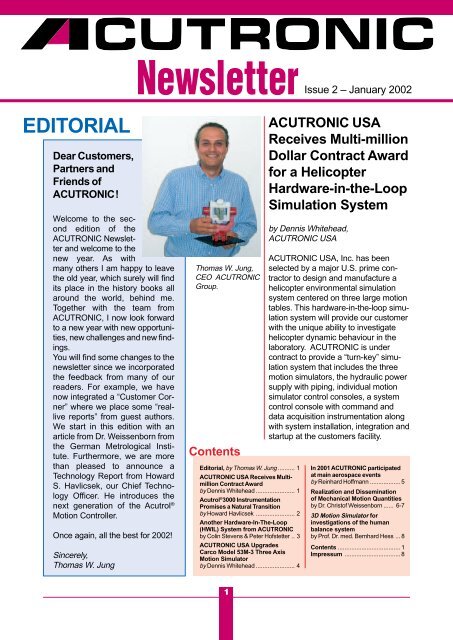
EDITORIAL<br />
Dear Customers,<br />
Partners and<br />
Friends of<br />
ACUTRONIC!<br />
Welcome to the second<br />
edition of the<br />
ACUTRONIC Newsletter<br />
and welcome to the<br />
new year. As with<br />
many others I am happy to leave<br />
the old year, which surely will find<br />
its place in the history books all<br />
around the world, behind me.<br />
Together with the team from<br />
ACUTRONIC, I now look forward<br />
to a new year with new opportunities,<br />
new challenges and new findings.<br />
You will find some changes to the<br />
newsletter since we incorporated<br />
the feedback from many of our<br />
readers. For example, we have<br />
now integrated a “Customer Corner”<br />
where we place some “reallive<br />
reports” from guest authors.<br />
We start in this edition with an<br />
article from Dr. Weissenborn from<br />
the German Metrological <strong>In</strong>stitute.<br />
Furthermore, we are more<br />
than pleased to announce a<br />
Technology Report from Howard<br />
S. Havlicsek, our Chief Technology<br />
Officer. He introduces the<br />
next generation of the Acutrol ®<br />
Motion Controller.<br />
Once again, all the best for 2002!<br />
Sincerely,<br />
Thomas W. Jung<br />
Newsletter<br />
Thomas W. Jung,<br />
CEO ACUTRONIC<br />
Group.<br />
Contents<br />
Editorial, by Thomas W. Jung .......... 1<br />
ACUTRONIC USA Receives Multimillion<br />
Contract Award<br />
by Dennis Whitehead ....................... 1<br />
Acutrol ® 3000 <strong>In</strong>strumentation<br />
Promises a Natural Transition<br />
by Howard Havlicsek ....................... 2<br />
<strong>Another</strong> <strong>Hardware</strong>-<strong>In</strong>-<strong>The</strong>-<strong>Loop</strong><br />
(<strong>HWIL</strong>) System from ACUTRONIC<br />
by Colin Stevens & Peter Hofstetter .. 3<br />
ACUTRONIC USA Upgrades<br />
Carco Model 53M-3 Three Axis<br />
Motion Simulator<br />
by Dennis Whitehead ....................... 4<br />
1<br />
ACUTRONIC NEWSLETTER<br />
Issue 2 – January 2002<br />
ACUTRONIC USA<br />
Receives Multi-million<br />
Dollar Contract Award<br />
for a Helicopter<br />
<strong>Hardware</strong>-in-the-<strong>Loop</strong><br />
Simulation System<br />
by Dennis Whitehead,<br />
ACUTRONIC USA<br />
ACUTRONIC USA, <strong>In</strong>c. has been<br />
selected by a major U.S. prime contractor<br />
to design and manufacture a<br />
helicopter environmental simulation<br />
system centered on three large motion<br />
tables. This hardware-in-the-loop simulation<br />
system will provide our customer<br />
with the unique ability to investigate<br />
helicopter dynamic behaviour in the<br />
laboratory. ACUTRONIC is under<br />
contract to provide a “turn-key” simulation<br />
system that includes the three<br />
motion simulators, the hydraulic power<br />
supply with piping, individual motion<br />
simulator control consoles, a system<br />
control console with command and<br />
data acquisition instrumentation along<br />
with system installation, integration and<br />
startup at the customers facility.<br />
<strong>In</strong> 2001 ACUTRONIC participated<br />
at main aerospace events<br />
by Reinhard Hoffmann .................. 5<br />
Realization and Dissemination<br />
of Mechanical Motion Quantities<br />
by Dr. Christof Weissenborn ...... 6-7<br />
3D Motion Simulator for<br />
investigations of the human<br />
balance system<br />
by Prof. Dr. med. Bernhard Hess ... 8<br />
Contents ..................................... 1<br />
Impressum ................................. 8
ACUTRONIC NEWSLETTER<br />
Acutrol ® 3000 <strong>In</strong>strumentation Promises a Natural Transition<br />
<strong>In</strong>to the Next Generation of Motion Control<br />
by Howard Havlicsek, ACUTRONIC R&D USA<br />
ACUTRONIC Research and Development<br />
(Pittsburgh, PA) is actively working on a next<br />
generation motion control instrumentation, called<br />
the Acutrol3000. Prototypes are currently being<br />
tested and demonstrated.<br />
<strong>The</strong> Acutrol ® ACT 2000 ® is the<br />
principal motion controller used by<br />
ACUTRONIC since the early 90’s, and<br />
has become an industry standard for<br />
high performance and reliability. From<br />
this legacy, the Acutrol3000 emerges<br />
offering a mix of features that provide a<br />
bridge to the future.<br />
<strong>The</strong> Acutrol3000 was developed with<br />
the following objectives:<br />
• Cost reduction by the use commercial<br />
off-the-shelf processors and<br />
interface modules.<br />
• Minimization of custom hardware<br />
using highly integrated FPGA technology.<br />
• High reliability (long MTBF) and<br />
‘calibrated’ transparency of hardware<br />
modules (short MTTR).<br />
• Commercial interfaces, which<br />
provide consistent protocols for realtime<br />
and language based communication.<br />
• An operator interface offered as an<br />
option rather than a requirement of<br />
the instrumentation.<br />
• Pure MACRO programming features<br />
embedded in the control software<br />
using the Python language.<br />
• Backward compatibility of principal<br />
interfaces to facilitate upgrading<br />
from the Acutrol ACT2000.<br />
• Asynchronous interfacing to realtime<br />
<strong>HWIL</strong> computers using event<br />
driven time-tags.<br />
2<br />
<strong>The</strong> Acutrol3000 instrumentation will<br />
be offered with various chassis configurations<br />
to satisfy a range of system<br />
requirements. User <strong>In</strong>terface options<br />
include an integrated touch panel PC,<br />
a separate panel or desktop PC, or no<br />
local interface. <strong>The</strong> heart of the control<br />
system includes the LynxOS real-time<br />
operating system running on a Pentium<br />
® + platform; and, a custom Axis<br />
<strong>In</strong>terface Module (AIM) that provides<br />
autonomous data acquisition of<br />
analog and digital signals for one axis<br />
of motion control.<br />
<strong>The</strong> ACUTRONIC Control Language<br />
(ACL) is used to communicate via non<br />
real-time interfaces such as<br />
IEEE488.2 and TCP/IP protocols. This<br />
control language is based on the<br />
GPIB interface protocol of the Acutrol<br />
ACT2000 and is greatly expanded to<br />
allow control, configuration, monitoring,<br />
and calibration of all aspects of<br />
the instrumentation. Data logging is<br />
provided as a new feature and includes<br />
multi-channel, event and level<br />
trigger modes with min, max, and<br />
multi-set averaging.<br />
Traditional control modes (Position,<br />
Rate, Track, and Synthesis) are<br />
implemented using an advanced<br />
JERK limited profiler that ensures<br />
smooth profiles and seamless transitions.<br />
An expansion of Track mode<br />
provides for various configurations of<br />
real-time control based on host computer<br />
frame rates, frame synchronization,<br />
and the complement of motion<br />
demand states. Real-time interfaces<br />
are implemented using either parallel<br />
PCI-DIO32HS(NI), or SCRAMNet ®<br />
(Systran) interface hardware.
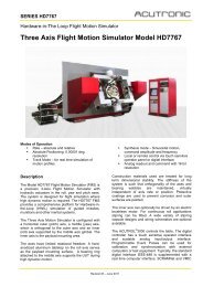
<strong>Another</strong> <strong>Hardware</strong>-<strong>In</strong>-<strong>The</strong>-<strong>Loop</strong><br />
(<strong>HWIL</strong>) System from ACUTRONIC<br />
by Colin Stevens & Peter Hofstetter,<br />
ACUTRONIC Switzerland<br />
ACUTRONIC Switzerland delivered and successfully<br />
installed a three-axis, high dynamic Flight<br />
Motion Simulator (FMS), Series HD7747. <strong>The</strong> system<br />
was designed, manufactured and integrated<br />
within the short time frame of fourteen months.<br />
3-axix flight motion<br />
simulator model<br />
HD7747 with test Unit<br />
Under Test (UUT)<br />
and ACUTROL ®<br />
control console.<br />
<strong>The</strong> FMS will be used within a RF<br />
environment and utilises an electrically<br />
driven translation carriage to locate the<br />
FMS into the anechoic chamber. <strong>In</strong><br />
order to achieve the high dynamic<br />
requirement the axes were driven by<br />
hydraulic actuators.<br />
<strong>The</strong> inner axis achieves accelerations<br />
of 35’000 0 /s 2 ; the middle and outer<br />
axes exceed 10’000 0 /s 2 .<br />
3<br />
ACUTRONIC NEWSLETTER<br />
Although ACUTROL ® is a digital<br />
controller it is able to accept and<br />
process inputs from analogue<br />
transducers. <strong>The</strong>se analogue inputs<br />
can be scaled digitally and routed to<br />
the digital servo loop. This feature of<br />
ACUTROL ® was used to process the<br />
input of accelerometers that were<br />
installed on the inner axis. <strong>The</strong> signals<br />
from the accelerometers gave feedforward<br />
compensation to the servo<br />
loop in order to reduce the phase lag of<br />
the axis.<br />
With the load attached and a constant<br />
input amplitude of 0.5 0 peak to peak,<br />
we achieved less than -10 0 phase lag<br />
at 10Hz. <strong>The</strong> amplitude was within<br />
+1dB from 0Hz to 30Hz.<br />
For real time motion control from the<br />
customer’s computer a high speed<br />
reflective memory interface<br />
(SCRAMNet ® ) was installed into the<br />
ACUTROL ® mainframe.<br />
Rear view of<br />
simulator showing<br />
accumulators,<br />
translation carriage<br />
and pipe work.
ACUTRONIC NEWSLETTER<br />
ACUTRONIC USA Upgrades Carco Model 53M-3<br />
Three Axis Motion Simulator<br />
by Dennis Whitehead, ACUTRONIC USA<br />
ACUTRONIC USA, <strong>In</strong>c. has just delivered a<br />
refurbished Model 53M-3 as shown in the photograph.<br />
<strong>The</strong> three-axis simulator was refurbished<br />
and delivered to a leading manufacturer of inertial<br />
navigation systems in the United States.<br />
ACUTRONIC Refurbished Model 53M-3 Three Axis Motion Simulator.<br />
4<br />
<strong>The</strong> table will be used to calibrate and<br />
test strap down <strong>In</strong>ertial Navigation<br />
Systems (INS) that require performance<br />
testing in controlled temperature<br />
environments in the range of -85° C to<br />
+85° C.<br />
<strong>The</strong> instrumentation upgrade improved<br />
the rate stability performance of each<br />
axis by an average factor of 10 times<br />
when compared to the original system<br />
performance as presented in the rate<br />
stability chart. <strong>The</strong> customer rate performance<br />
goals were 0.05% stability<br />
over 1 degree and 0.01% over 1 degree<br />
throughout the entire rate range of the<br />
table. As a minimum, on any axis at any<br />
axis rate, the rate stability performance<br />
was at least 0.0029%. This value was<br />
more than 3 times better than the goal<br />
specified by the customer. Typically, axis<br />
rate stabilities were 0.001%, which is 50<br />
times better than the customers’ specification.<br />
<strong>The</strong> refurbishment included the<br />
replacement of the obsolete MPACS<br />
motion controller and the MACS drive<br />
power amplifier instrumentation with the<br />
“field proven” Acutrol ACT2000 Digital<br />
Motion Control System and the ACU-<br />
TRONIC PA2500 Drive Power Amplifiers.<br />
An ACUTRONIC designed temperature<br />
chamber control chassis was implemented<br />
for precise control of the temperature<br />
chamber. This temperature<br />
control chassis used a dual-loop temperature<br />
controller to provide improved temperature<br />
regulation of the payload and<br />
optimized ramp times.<br />
<strong>The</strong> original drive motors on each axis<br />
were replaced with higher torque AC<br />
brushless drive motors to improve axis<br />
accelerations and maximum axis velocities.<br />
Brushless drive motor commutation<br />
was processed within the Acutrol<br />
controller. <strong>The</strong> original inner gimbal was
Axis 1 Positive Rates - Average Stability<br />
Top Curve: Original Data with MPACS/MACS. Middle Curve: With<br />
Acutrol. Bottom Curve: With Acutrol, Power Amplifiers, Motors, and<br />
Acutrol Commutation (Rate Stability Improves by a Factor of 10).<br />
Axis 1 Rate Stability Data over 1 Degree <strong>In</strong>tervall.<br />
44 th <strong>In</strong>ternational Paris Air<br />
Show from 17 th to 24 th June<br />
2001<br />
<strong>The</strong> 2001 Paris Air Show<br />
offered an unsurpassed opportunity<br />
to display products, technologies<br />
and services. <strong>The</strong> AC-<br />
UTRONIC stand within the<br />
Swiss Pavilion area attracted<br />
visitors, customers and officials<br />
with a live demonstration of a<br />
Two Axis Motion Simulator and<br />
a continuous video presentations<br />
of ACUTRONIC key products.<br />
A considerable amount of contact<br />
papers were received with<br />
very interesting application<br />
notes.<br />
Rate (deg//sec)<br />
Rate Stability (%) vs Rate (deg/sec)<br />
removed and replaced with a double<br />
tabletop configuration and a temperature<br />
chamber cooled with liquid nitrogen.<br />
<strong>The</strong> temperature chamber was secured<br />
to the middle gimbal and the tabletop<br />
configuration was supported by an inner<br />
axis shaft extension protruding through<br />
As a summary, it can be stated<br />
that the Paris Air Show fulfilled its<br />
role as the most significant professional<br />
international Exhibition.<br />
<strong>In</strong>ternational Aviation and<br />
Space Salon MAKS 2001,<br />
MOSCOW from 14 th to 19 th<br />
August<br />
ACUTRONIC attended the MAKS<br />
2001 <strong>In</strong>ternational Air and Space<br />
Salon, Moscow for the second<br />
time in cooperation with our Russian<br />
Partner DAVIA / Aviapribor.<br />
<strong>The</strong> stands of the Aviapribor<br />
Company and the stands of a<br />
number of other larger Russian<br />
design- and production partners<br />
were arranged within the domi-<br />
5<br />
ACUTRONIC NEWSLETTER<br />
the bottom wall in the chamber allowing<br />
the double tabletop arrangement to<br />
rotate inside the temperature chamber.<br />
This new inner axis configuration significantly<br />
reduced the inner axis inertia, but<br />
also doubled the payload capacity for<br />
the customer. <strong>In</strong>ner axis modifications<br />
resulted in peak acceleration and velocity<br />
performance that was at least two<br />
times better than original system specifications.<br />
<strong>The</strong> middle gimbal was dynamically<br />
balanced to minimize variations<br />
in inertia during simultaneous axis<br />
rotations. Dynamic balancing also minimizes<br />
the gyroscopic torque disturbances<br />
between test table axes.<br />
New slipring assemblies were installed<br />
on each of the three axes. High capacity<br />
power rings were implemented on the<br />
outer and middle axes; this design consisted<br />
of slipring assemblies that separated<br />
all power circuits from the payload<br />
slip ring circuits. <strong>The</strong> slipring upgrade<br />
provided increased power capacity on<br />
the power circuits to maximize slipring<br />
reliability and provide isolation from the<br />
customers’ payload slipring circuits.<br />
<strong>In</strong> 2001 ACUTRONIC participated at main aerospace events<br />
in order to expand and strengthen international customer relations.<br />
By Reinhard Hoffmann, ACUTRONIC Germany<br />
nant, individual Sukhoi Aircraft<br />
Company pavilion. Beside an<br />
operating Motion Simulator, the<br />
current ACUTRONIC company<br />
video was presented in sequence<br />
with Aviapribor videos<br />
on a large digital projector<br />
screen.<br />
This event was a central place<br />
to discuss both the technology<br />
with engineers and the business<br />
with responsible, highly ranked<br />
managers. It was realized that<br />
many new projects are planned<br />
where motion simulators are<br />
necessary. Delegations from<br />
Russian- and CIS-industry partners<br />
and -customers visited the<br />
combined stand in order to see<br />
the presented material and to<br />
get brief introductions
ACUTRONIC NEWSLETTER<br />
Realization and Dissemination of<br />
Mechanical Motion Quantities<br />
<strong>The</strong> Metrological Application of the ACUTRONIC Model 170.01<br />
by Dr. Christof Weissenborn, Physikalisch-Technische Bundesanstalt, Germany<br />
<strong>The</strong> new multicomponent calibration system developed<br />
and put into operation at PTB, will open<br />
up new vistas for the identification of sensor characteristics<br />
and the evaluation of mechanical structures.<br />
<strong>The</strong> ‘rotational axis‘ is a custom single axis<br />
rate table designed by ACUTRONIC to meet the<br />
specific requirements of PTB.<br />
Performance specification table<br />
<strong>The</strong> Physikalisch-Technische Bundesanstalt<br />
(PTB), Braunschweig and<br />
Berlin, is the national metrological<br />
institute (NMI) of natural and engineering<br />
sciences and the highest technical<br />
authority for metrology and physical<br />
safety engineering of the Federal<br />
Republic of Germany. Metrology,<br />
understood as the “art of careful<br />
measurement”, is as old as the history<br />
of technology of mankind.<br />
<strong>The</strong> manufacturers and users of transducers<br />
and instruments for measuring<br />
motion quantities are under increasing<br />
pressure to establish and ensure<br />
traceability to national standards. A<br />
traceability system has been developed<br />
at the NMI level based on primary<br />
vibration calibration using laser<br />
interferometry. Calibration includes the<br />
three translational motion quantities,<br />
acceleration, velocity and displacement,<br />
and the three rotational motion<br />
quantities, angular acceleration, angular<br />
velocity and rotation angle.<br />
max. angular acceleration >1000 rad/s 2<br />
frequency range 0,1 Hz to >1000 Hz<br />
max. angular rate ± 180 rad/s<br />
max. torque 30 Nm<br />
max. rate deviation ± 0,004 %<br />
max. axis wobble error 0,33 arcsec<br />
6<br />
<strong>The</strong> multi-axis excitation system at<br />
PTB consists of three linear electrodynamic<br />
exciters, which are coupled by<br />
hydrostatic bearings. <strong>The</strong> ACUTRON-<br />
IC exciter, AC 170.01 provides a<br />
(fourth) rotational degree of freedom<br />
and is mounted on top of the three<br />
axis table. Due to the combination of<br />
translational and rotational motion a<br />
wide variety of sensor testing can be
Motion Simulator<br />
Model 170.01<br />
Motion Simulator<br />
Model 170.01 on<br />
three linear electrodynamic<br />
exciters<br />
carried out, e.g. modelling the behaviour<br />
of a gyroscopic yaw sensor used<br />
in vehicles subject to the conditions of<br />
real-world 3D environmental vibrations.<br />
PTB specified the desired performance<br />
very close to the limit of today’s<br />
technology. Even so, the results of the<br />
ACUTRONIC AC 170.01 are quite<br />
outstanding.<br />
<strong>The</strong> unique behaviour has been<br />
achieved by means of extraordinary<br />
effort: <strong>The</strong> precise motion is assured<br />
by an air bearing, whose H-shape, with<br />
a hollow shaft and two baffles, has a<br />
high stiffness in both radial and axial<br />
directions. On the control side, acceleration<br />
feedback provides a third physical<br />
quantity in addition to rotation angle<br />
and rate for closed loop control. <strong>The</strong><br />
angular accelerometer Model 110-A of<br />
ACUTRONIC delivers the essential<br />
information for indicating the desired<br />
7<br />
ACUTRONIC NEWSLETTER<br />
mechanical motion of the table.<br />
Moreover, the capability of external<br />
control of the whole exciter by an iterative<br />
control system adds a <strong>HWIL</strong>-feature<br />
to the AC 170.<br />
Currently, the table is equipped with<br />
two specially invented miniature retroreflector<br />
interferometers, which establish<br />
the primary vibration calibration.<br />
With this system, a new level of understanding<br />
the many interrelated effects<br />
compromising the mechanical input to<br />
any inertial transducer is realized.<br />
For further information, please contact:<br />
Physikalisch-Technische<br />
Bundesanstalt<br />
Dr.-<strong>In</strong>g. Christof Weissenborn<br />
Fachlaboratorium 1.22<br />
Beschleunigung<br />
Bundesallee 100<br />
38116 Braunschweig<br />
phone: +49 531 592 1221<br />
email: Christof.Weissenborn@ptb.de
ACUTRONIC NEWSLETTER<br />
3D Motion Simulator for investigations<br />
of the human balance system<br />
Vestibulo-Oculomotor Laboratory, University Hospital Zurich<br />
by Prof. Dr. med. Bernhard Hess, Department of Neurology, University of Zurich<br />
A servo-controlled gimbal<br />
system with three motorized<br />
and two manually adjustable<br />
axes, constructed by<br />
ACUTRONIC Switzerland AG<br />
(1999), allows static and<br />
dynamic investigations of the<br />
sensory organs that detect<br />
our orientation and movement<br />
in space.<br />
On the research front, the<br />
device is used to investigate<br />
the psychophysics of spatial<br />
orientation, the mechanisms of<br />
the human balance system,<br />
and the processing of visual<br />
and vestibular information by<br />
the central nervous system. <strong>In</strong><br />
addition, the 3D Motion Simulator<br />
is also used to treat patients<br />
suffering from certain disorders<br />
of the balance system.<br />
ACUTRONIC Schweiz AG<br />
Techcenter Schwarz<br />
8608 Bubikon, Switzerland<br />
ACUTRONIC USA <strong>In</strong>c.<br />
139 Delta Drive<br />
Pittsburg, PA 15238, USA<br />
ACUTRONIC Deutschland GmbH<br />
Bretonischer Ring 15<br />
85630 Grasbrunn, Germany<br />
ACUTRONIC R&D, USA<br />
139 Delta Drive<br />
Pittsburg, PA 15238, USA<br />
Note:<br />
A live demonstration of the<br />
turntable can be found at<br />
http: //web.unispital.ch/<br />
neurologie/vest/<br />
human_turntable.htm<br />
phone (055) 253 23 23<br />
telefax (055) 253 23 33<br />
e-mail: office@acutronic.com<br />
phone (412) 963 9400<br />
telefax (412) 963 0816<br />
e-mail: aus@acutronic.com<br />
phone (089) 46 30 85<br />
telefax (089) 46 46 77<br />
e-mail: info@acutronic.de<br />
phone (412) 963 9400<br />
telefax (412) 963 0519<br />
e-mail: ard@acutronic.com<br />
ACUTRONIC – your long-term partner for system responsibility<br />
Please visit our Home Page: www.acutronic.com<br />
8<br />
Impressum:<br />
3D Motion<br />
Simulator.<br />
Editor:<br />
Anne-Marie Crijns<br />
ACUTRONIC Deutschland GmbH<br />
Bretonischer Ring 15<br />
D- 85630 Grasbrunn<br />
phone: +49 89 46 30 85<br />
email: alorbeer@acutronic.com<br />
We would welcome your feedback<br />
for improvement and new ideas.<br />
Please feel free to contact our editor<br />
Mrs. Anne-Marie Crijns<br />
(former Anne-MArie Lorbeer).