air line equipment - Norgren Pneumatics. Motion Control Equipment ...
air line equipment - Norgren Pneumatics. Motion Control Equipment ...
air line equipment - Norgren Pneumatics. Motion Control Equipment ...

Create successful ePaper yourself
Turn your PDF publications into a flip-book with our unique Google optimized e-Paper software.
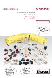
AIR LINE EQUIPMENT<br />
AIR LINE EQUIPMENT<br />
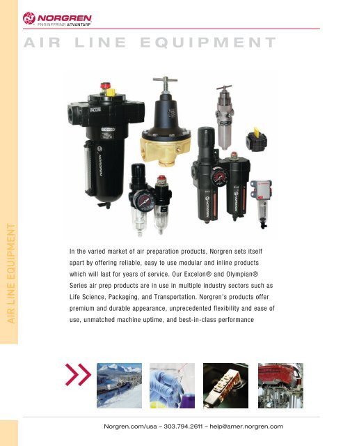
In the varied market of <strong>air</strong> preparation products, <strong>Norgren</strong> sets itself<br />
apart by offering reliable, easy to use modular and in<strong>line</strong> products<br />
which will last for years of service. Our Excelon® and Olympian®<br />
Series <strong>air</strong> prep products are in use in multiple industry sectors such as<br />
Life Science, Packaging, and Transportation. <strong>Norgren</strong>’s products offer<br />
premium and durable appearance, unprecedented flexibility and ease of<br />
use, unmatched machine uptime, and best-in-class performance<br />
<strong>Norgren</strong>.com/usa – 303.794.2611 – help@amer.norgren.com
Excelon ®<br />
Modular<br />
system<br />
filters<br />
Excelon<br />
Modular<br />
system<br />
pressure<br />
regulators<br />
Excelon<br />
Modular<br />
system oil<br />
and microfog<br />
lubricators<br />
AIR LINE EQUIPMENT<br />
Filter/Regulator-Lubricator<br />
boxed sets<br />
1/4" to 1/2"<br />
250 psig*<br />
0°F to 150°F*<br />
ALE-3 ALE-4 ALE-6<br />
F72C, F73C, F74C, F74H<br />
Oil removal filters<br />
1/4" to 3/4"<br />
250 psig*<br />
-30°F to -<br />
150°F*<br />
ALE-8 ALE-10<br />
B72G, B73G, B74G<br />
Filter/regulators<br />
1/4" to 3/4"<br />
250 psig*<br />
-30F to 175°F<br />
ALE-14 ALE-16<br />
R72G, R73G, R74G<br />
1/4" to 3/4"<br />
300 psig<br />
-30°F to 175°F<br />
ALE-18 ALE-20<br />
L72M/C, L73M/C, L74M/C<br />
1/4" to 1/2"<br />
250 psig*<br />
-30°F to 175°F*<br />
ALE-22 ALE-24<br />
F72G, F73G, F74G<br />
General purpose filters<br />
1/4" to 3/4"<br />
250 psig*<br />
-30° to 175°F<br />
F92C Excelon PRO<br />
Oil removal filter<br />
1/4"<br />
116 psig<br />
-4°F to 125°F<br />
B92G Excelon PRO<br />
Filter/regulator<br />
1/4"<br />
175 psig*<br />
-4°F to 125°F<br />
R92G Excelon PRO<br />
1/4"<br />
175 psig<br />
-4°F to 140°F<br />
L92C Excelon PRO<br />
1/4"<br />
175 psig<br />
-4°F to 125°F<br />
<strong>Norgren</strong>.com/usa – 303.794.2611 – help@amer.norgren.com<br />
F92G Excelon PRO<br />
General purpose filter<br />
1/4"<br />
175 psig*<br />
-4° to 125°F<br />
F72V, F74V<br />
Oil vapor removal filter<br />
1/4", 1/2", 3/4"<br />
250 psig*<br />
0°F to 150°F*<br />
ALE-12<br />
* See catalog page<br />
ALE-A<br />
AIR LINE EQUIPMENT
AIR LINE EQUIPMENT<br />
AIR LINE EQUIPMENT<br />
Excelon<br />
Modular<br />
pressure<br />
relief<br />
valves<br />
Excelon<br />
combination<br />
units<br />
Excelon<br />
Smooth<br />
start,<br />
Directional,<br />
and<br />
Lockout<br />
Valves<br />
* See catalog page<br />
ALE-B<br />
V72G, V74G<br />
1/4" to 3/4"<br />
300 psig<br />
-30°F to 175°F*<br />
ALE-26<br />
H72G/C, H73G/C, H74G/C<br />
Filter-Filter<br />
1/4" to 3/4"<br />
150 psig*<br />
-30°F to 150°F*<br />
ALE-28 ALE-29 ALE-30<br />
C72C, C73C, C74C<br />
Filter-Lubricator<br />
1/4" to 3/4"<br />
250 psig*<br />
-30°F to 175°F*<br />
ALE-31<br />
P72F, P74F, P74F-AD<br />
Smooth Start/exhaust<br />
1/4" to 3/4"<br />
150 psig<br />
0°F to 175°F*<br />
ALE-32 ALE-34<br />
T92, T72, T73, T74,<br />
Smooth Start/exhaust<br />
1/4" to 3/4"<br />
250 psig<br />
-30°F to 150°F<br />
ALE-36<br />
B72/L72, B73/L73, B74/L74<br />
Filter/Regulator-<br />
Lubricator<br />
1/4" to 3/4"<br />
250 psig*<br />
0°F to 150°F*<br />
P92E, P72C/E, P74E, P74<br />
Smooth Start valves<br />
1/4" to 1/2"<br />
C72A, C73A, C74A<br />
Filter-Regulator-<br />
Lubricator<br />
1/4" to 3/4"<br />
250 psig<br />
-30°F to 175°F*<br />
P92C, P74<br />
1/4" to 1/2"<br />
Directional <strong>Control</strong><br />
valves, threaded and<br />
unthreaded ports<br />
ALE-35<br />
<strong>Norgren</strong>.com/usa – 303.794.2611 – help@amer.norgren.com
Olympian<br />
Plus<br />
Modular<br />
system<br />
filters<br />
Olympian<br />
Plus<br />
Modular<br />
system<br />
regulators<br />
Olympian<br />
Plus<br />
Modular<br />
pressure<br />
relief<br />
valves<br />
Olympian<br />
Plus<br />
Modular<br />
lockout<br />
valves<br />
AIR LINE EQUIPMENT<br />
F64G, F68E<br />
General purpose filters<br />
1/2", 1"<br />
250 psig*<br />
-30°F to 175°F*<br />
ALE-40 ALE-42<br />
F64B/L, F68V/Y<br />
Vapor removal filters<br />
1/4" to 3/4"<br />
250 psig*<br />
-30°F to 125°F*<br />
F64C/H,<br />
F68C/H<br />
Oil removal filters<br />
1/4" to 1"<br />
240 psig*<br />
-30°F to 125°F*<br />
B64G, B68E/G<br />
Filter/regulators<br />
1/2" to 1-1/2"<br />
250 psig*<br />
-30°F to 175°F*<br />
ALE-44 ALE-46<br />
R64G/R, R68G<br />
General purpose<br />
1/2" to 1-1/2"<br />
250 psig*<br />
-30°F to 175°F*<br />
ALE-48<br />
V64H, V68H<br />
1/2" to 1-1/2"<br />
300 psig*<br />
-30°F to 175°F*<br />
ALE-52<br />
T64, T68<br />
1/4" to 3/4"<br />
250 psig<br />
0°F to 175°F<br />
ALE-56<br />
Olympian<br />
Plus<br />
Modular<br />
system<br />
lubricators<br />
Olympian<br />
Plus Modular<br />
smooth<br />
start/exhaust<br />
valves<br />
<strong>Norgren</strong>.com/usa – 303.794.2611 – help@amer.norgren.com<br />
L64M/C, L68M/C<br />
1/2" to 1-1/2"<br />
250 psig*<br />
-30°F to 175°F*<br />
ALE-50<br />
P64F, P68F<br />
1/2" to 1-1/2"<br />
250 psig<br />
0°F to 175°F*<br />
ALE-54<br />
* See catalog page<br />
ALE-C<br />
AIR LINE EQUIPMENT
AIR LINE EQUIPMENT<br />
AIR LINE EQUIPMENT<br />
Miniature<br />
Series<br />
Ported in<strong>line</strong><br />
FRL’s<br />
* See catalog page<br />
ALE-D<br />
Series PTH<br />
Filter/Regulatorlubricator<br />
1/8" - 1/4"<br />
250 psig*<br />
0°F to 150°F*<br />
ALE-58<br />
R07, R46<br />
General purpose regulator<br />
1/8", 1/4"<br />
300 psig*<br />
-30°F to 150°F*<br />
ALE-62<br />
F17<br />
General purpose filter<br />
3/4" to 1-1/2"<br />
250 psig<br />
-30°F to 175°F<br />
ALE-68<br />
F47<br />
Oil removal filter<br />
1-1/2", 2"<br />
250 psig<br />
-30°F to 150°F<br />
ALE-71<br />
F07<br />
General purpose filter<br />
1/8", 1/4"<br />
250 psig*<br />
-30°F to 175°F*<br />
ALE-60<br />
B07, B39<br />
Filter/Regulators<br />
1/8", 1/4"<br />
250 psig*<br />
-30°F to 150°F*<br />
ALE-64<br />
F18<br />
General purpose filter<br />
1-1/2", 2"<br />
250 psig<br />
-30°F to 175°F<br />
ALE-69<br />
R17, R18<br />
General purpose regulator<br />
3/4" to 2"<br />
450 psig<br />
-30°F to 175°F*<br />
ALE-72<br />
F39<br />
Oil removal filter<br />
1/8", 1/4"<br />
250 psig*<br />
-30°F to 150°F*<br />
ALE-61<br />
L07<br />
Micro-fog lubricator<br />
1/8", 1/4"<br />
250 psig*<br />
0°F to 175°F*<br />
ALE-66<br />
F46<br />
Oil removal filter<br />
3/4", 1", 1-1/4"<br />
250 psig<br />
-30°F to 150°F<br />
ALE-70<br />
<strong>Norgren</strong>.com/usa – 303.794.2611 – help@amer.norgren.com
Pressure,<br />
Micro-Trol,<br />
and<br />
Instrument<br />
Regulators<br />
Pilot and<br />
Feedback<br />
Regulators<br />
Manifolding<br />
Regulators<br />
AIR LINE EQUIPMENT<br />
11-002 & 20AG<br />
Pressure regulator<br />
1/4", 3/8", 1/2"<br />
G3/4, G1<br />
400 psig<br />
-30°F to 175°F<br />
ALE-74<br />
R38 Instrument, and<br />
B38 filter/regulator<br />
1/4"<br />
290 psig<br />
-40°F to 175°F<br />
ALE-80<br />
R40, R41<br />
Pilot, and Feedback<br />
1/4"<br />
450 psig<br />
0°F to 175°F<br />
ALE-82 ALE-84<br />
11-042, 11-008<br />
Pilot operated regulator<br />
1/4" to 1-1/4"<br />
400 psig<br />
0°F to 175°F<br />
ALE-88<br />
R72M, R74M<br />
1/4" - 3/4"<br />
290 psig<br />
-30°F to 150°F<br />
R24<br />
Micro-Trol<br />
pressure regulator<br />
1/4" to 1-1/4"<br />
300 psig<br />
0°F to 150°F<br />
ALE-76 ALE-78<br />
11-400, 20AL<br />
Pilot Feedback<br />
1/4"<br />
360 psig<br />
0°F to 175°F<br />
R18, R24<br />
Pilot operated regulator<br />
1/4" to 2"<br />
450 psig<br />
0°F to 175°F<br />
ALE-90<br />
R30M<br />
8 mm, 10 mm<br />
150 psig<br />
23°F to 104°F<br />
ALE-92 ALE-94<br />
<strong>Norgren</strong>.com/usa – 303.794.2611 – help@amer.norgren.com<br />
11-018<br />
Precision regulator<br />
1/4"<br />
200 psig*<br />
32°F to 160°F<br />
11-104<br />
Feedback pilot<br />
1/4"<br />
400 psig<br />
0°F to 175°F<br />
ALE-86<br />
* See catalog page<br />
ALE-E<br />
AIR LINE EQUIPMENT
AIR LINE EQUIPMENT<br />
AIR LINE EQUIPMENT<br />
Stainless<br />
Steel<br />
products<br />
Water or Air<br />
Regulators<br />
In<strong>line</strong> Micro-<br />
Fog and Oil<br />
Fog<br />
lubricators<br />
* See catalog page<br />
ALE-F<br />
R05, B05<br />
Regulator, and<br />
filter/regulator<br />
1/4"<br />
300 psig<br />
-30°F to 150°F<br />
ALE-96<br />
R06<br />
Brass miniature<br />
1/8", 1/4"<br />
400 psig<br />
-30°F to 150°F*<br />
ALE-102<br />
R91<br />
Pressure regulator<br />
1/4"<br />
150 psig<br />
0°F to 125°F*<br />
ALE-108<br />
L17<br />
3/4" to 1-1/2"<br />
250 psig<br />
0°F to 175°F<br />
ALE-112<br />
R38, B38<br />
Regulator, and<br />
filter/regulator<br />
1/4", 1/2"<br />
450°F<br />
-40°F to 175°F<br />
F22, R22, L22<br />
Filter, Regulator,<br />
Lubricator<br />
1/2"<br />
250 psig<br />
0°F to 175°F<br />
ALE-98 ALE-100<br />
R14, R16<br />
Miniature, preset,<br />
nonadjustable<br />
1/8", 1/4"<br />
400 psig<br />
-30°F to 150°F<br />
ALE-104 ALE-106<br />
R91<br />
Water regulator<br />
1/4" to 1"<br />
400 psig<br />
-30°F to 200°F*<br />
ALE-110<br />
10-028, 10-076<br />
Oil-fog<br />
1-1/2", 2"<br />
250 psig<br />
0°F to 175°F<br />
ALE-114<br />
11 044<br />
Pressure regulator<br />
1/4" tube connecton<br />
250 psig<br />
-30°F to 150°F*<br />
<strong>Norgren</strong>.com/usa – 303.794.2611 – help@amer.norgren.com
Pressure<br />
relief valves<br />
UL Listed<br />
Regulators<br />
Additional<br />
Products<br />
18-013, 5PG<br />
Gauges<br />
AIR LINE EQUIPMENT<br />
V07, 16-004, V06<br />
1/8", 1/4"<br />
300 psig<br />
-30°F to 200°F*<br />
ALE-116<br />
R44, R83<br />
1/8", 1/4"<br />
250 psig<br />
-30°F to 140°F<br />
ALE-120 ALE-122<br />
CS13, CS15<br />
Coalescing exhaust<br />
slencers<br />
1/4" - 1-1/2"<br />
In<strong>line</strong><br />
Lockout<br />
Valves<br />
R81, R82, R84<br />
Soft drink, beer<br />
dispensing<br />
1/4"<br />
3000 psig<br />
0°F to 140°F<br />
ALE-124 ALE-124<br />
BS Series<br />
Blow guns<br />
1/8", 1/4"<br />
ALE-125 ALE-125<br />
17-001<br />
High pressure needle valves<br />
1/8", 1/4"<br />
Dryers<br />
ALE-126<br />
<strong>Norgren</strong>.com/usa – 303.794.2611 – help@amer.norgren.com<br />
C00<br />
1/4" to 1-1/2"<br />
300 psig<br />
-20° to 175°F<br />
ALE-118<br />
17-016<br />
Drip leg drain<br />
1/2"<br />
ALE-124<br />
Air Prep<br />
Accessories<br />
ALE-129<br />
2.32 (59)<br />
0.59<br />
(15)<br />
2.91 (74)<br />
* See catalog page<br />
ALE-G<br />
AIR LINE EQUIPMENT
AIR LINE EQUIPMENT<br />
DEMAND MORE FLEXIBILITY WITH NORGREN’S<br />
Excelon Pro Design Advantage<br />
»<br />
»<br />
»<br />
Design flexibility<br />
Excelon Pro’s ease of assembly allows last minute<br />
changes in product configuration.<br />
Aesthetic appearance<br />
Excelon Pro units have a contemporary, modern<br />
appearance designed to enhance any product or<br />
application.<br />
ALE-2<br />
Small Footprint<br />
The compact unit size coupled with integrated fitting<br />
connections make the Excelon Pro the most compact<br />
unit in its class.<br />
»<br />
»<br />
»<br />
Ease of Installation<br />
Innovative patent pending connection design combined<br />
with integral mounting brackets make the Excelon Pro<br />
user friendly and easy to install.<br />
Integrated fittings<br />
Integrated fittings reduce installation time, minimize leak<br />
paths, and reduce overall footprint dimensions. Offered in<br />
1/4", 3/8", 1/2", 6 mm, 8 mm, 10 mm and 12 mm sizes.<br />
Flow performance<br />
Patent pending valve provides breakthrough flow capacity.<br />
Maximum flow for such a compact product.<br />
<strong>Norgren</strong>.com/usa – 303.794.2611 – help@amer.norgren.com
Excelon ® Filter/Regulator-Lubricator<br />
Boxed Sets<br />
B72/L72, B73/L73, B74/L74<br />
Boxed sets are an excellent and<br />
attractive marketing tool for counter<br />
displays.<br />
True modularity with <strong>Norgren</strong><br />
Quikclamp ® connections<br />
Quick release bayonet bowl<br />
Lubricator flow sensor provides a<br />
nearly constant oil/<strong>air</strong> ratio over a<br />
wide range of <strong>air</strong> flows<br />
All around (360°) visibility of the<br />
lubricator sight-feed dome simplifies<br />
installation and adjustment<br />
Regulator balanced valve minimizes<br />
effect of variation in the inlet<br />
pressure on the outlet pressure<br />
Technical data<br />
Fluid:<br />
Compressed <strong>air</strong>, neutral gases<br />
NOTE: Contact <strong>Norgren</strong> for use with other media.<br />
Maximum pressure:<br />
Transparent bowl: 150 psig (10 bar)<br />
Metal bowl (manual or semi automatic<br />
drain): 250 psig (17 bar)<br />
(72) 150 psig (10 bar)<br />
Operating temperature*:<br />
Transparent bowl:<br />
0° to 125°F (-20° to 50°C)<br />
Metal bowl:<br />
0° to 150°F (-20° to 65°C)<br />
* Air supply must be dry enough to avoid ice formation at<br />
temperatures below 35°F (2°C ).<br />
Particle removal:<br />
40 µm filter element<br />
Materials<br />
Body: zinc or aluminum<br />
Bonnet: acetal or aluminum<br />
Bowl:<br />
Metal bowl: (72) polycarbonate<br />
(73, 74) aluminum<br />
Metal bowl liquid level indicator lens:<br />
transparent nylon<br />
Sight-feed dome: transparent nylon<br />
Element: sintered polypropylene<br />
Elastomers: neoprene, nitrile<br />
Other combinations are available.<br />
Please consult <strong>Norgren</strong> for more<br />
information.<br />
1.50<br />
(38)<br />
Ordering information<br />
Models include PTF threads. Filter/Regulator (F/R) has knob adjustment, automatic drain, metal bowl with level indicator, 40 µm element,<br />
relieving diaphragm, and 150 psig (10 bar) regulating spring, and gauge. Lubricator (L) is a Micro-Fog model with 1/4 turn manual drain<br />
and metal bowl with level indicator. Shut off valve is included.<br />
2.32 (59)<br />
Boxed sets<br />
Boxed Set Combination Units (ship within 24 hours)<br />
Boxed Set Port size Model<br />
Filter/Regulator-Lubricator-Lockout valve-gauge-brackets 1/4" BL72-201A<br />
Filter/Regulator-Lubricator-Lockout valve-gauge-brackets 3/8" BL73-301A<br />
Filter/Regulator-Lubricator-Lockout valve-gauge-brackets 1/2” BL74-401A<br />
6.46 (164)<br />
2.11 (54) 2.24 (56) 2.11 (54)<br />
BL72-201A<br />
Dimensions in inches (mm).<br />
<strong>Norgren</strong>.com/usa – 303.794.2611 – help@amer.norgren.com<br />
5.83 (148)<br />
3.25<br />
(83) 2.00 (51)<br />
2.40<br />
(61)<br />
8.58 (218)<br />
3.23 (82)<br />
BL73-301A<br />
2.95<br />
(75)<br />
6.15 (156)<br />
BL72-201A<br />
2.00 (51)<br />
3.25<br />
(83)<br />
3.03<br />
(77)<br />
10.13 (257)<br />
3.68<br />
(94)<br />
3.42<br />
(87)<br />
BL74-401A<br />
6.95 (177)<br />
ALE-3<br />
AIR LINE EQUIPMENT
AIR LINE EQUIPMENT<br />
Excelon ® Modular System<br />
F72G, F73G, F74G General Purpose Filters<br />
Excelon ® design allows in-<strong>line</strong> or<br />
modular installation with other<br />
Excelon ® products<br />
Quick release bayonet bowl<br />
Highly visible prismatic liquid level<br />
indicator lens on metal bowls<br />
Technical data<br />
Fluid: Compressed <strong>air</strong>, neutral gases<br />
NOTE: Contact <strong>Norgren</strong> for use with other media.<br />
Maximum pressure:<br />
Transparent bowl: 150 psig (10 bar)<br />
Metal bowl: 250 psig (17 bar)<br />
F72G w/metal bowl and automatic<br />
drain: 150 psig (10 bar)<br />
Operating temperature*:<br />
Transparent bowl: -30° to 125°F<br />
(-34° to 50°C)<br />
Metal bowl:<br />
(72) -30° to 150°F (-34° to 66°C)<br />
(73, 74) -30° to 175°F (-34° to 80°C)<br />
* Air supply must be dry enough to avoid ice formation at<br />
temperatures below 35°F (2°C) .<br />
Materials<br />
F72G<br />
Body: zinc<br />
Transparent bowl: polycarbonate<br />
Metal bowl: zinc<br />
Metal bowl liquid level indicator lens:<br />
transparent nylon<br />
Element: sintered polypropylene<br />
Elastomers: neoprene and nitrile<br />
F73G & F74G:<br />
Body: aluminum<br />
Transparent bowl: polycarbonate<br />
Transparent with guard: polycarbonate,<br />
aluminum guard<br />
Metal bowl: aluminum<br />
Metal bowl liquid level indicator lens:<br />
transparent nylon<br />
Element: sintered polypropylene<br />
Elastomers: Neoprene and nitrile<br />
ALE-4<br />
Ordering information<br />
Models listed include PTF threads, automatic drain, metal bowl with liquid level indicator, and a 40 µm element.<br />
Port Size Model Flow† scfm (dm3/s) Weight lb (kg)<br />
1/4" F72G 2AN AE3 55 (26) 1.15 (0.52)<br />
3/8" F73G 3AN AD3 65 (31) 1.1 (0.50)<br />
1/2" F74G 4AN AD3 140 (66) 1.79 (0.81)<br />
3/4" F74G 6AN AD3 140 (66) 1.75 (0.79)<br />
† Typical flow with a 40µm element at 90 psig (6.3 bar) inlet pressure and 5 psig (0.35 bar) pressure drop.<br />
Options selector<br />
Series Substitute<br />
72 2<br />
73 3<br />
74 4<br />
Port size Substitute<br />
1/4 (72, 73) 2<br />
3/8 (72, 73 74) 3<br />
1/2 (73, 74) 4<br />
3/4 (74) 6<br />
Threads Substitute<br />
PTF A<br />
ISO G parallel G<br />
Service life indicator Substitute<br />
Mechanical indicator D<br />
Electrical indicator E<br />
Without N<br />
F72G F73G F74G<br />
ISO Symbols<br />
Auto Drain Manual Drain<br />
F7˙G ˙˙˙ ˙˙˙<br />
Element Substitute<br />
5 µm 1<br />
40 µm 3<br />
Bowl Substitute<br />
Metal w/ liquid level indicator (72*, 73, 74) D<br />
Long metal w/ liquid level indicator (72)* E<br />
Long transparent (72)* L<br />
Transparent with guard (73, 74) P<br />
Transparent bowl (72*, 73) T<br />
Drain Substitute<br />
1/4 turn manual Q<br />
Auto drain* A<br />
* 72 Series auto drain is available only with long bowl option.<br />
<strong>Norgren</strong>.com/usa – 303.794.2611 – help@amer.norgren.com
Accessories<br />
F72G, F73G, F74G General Purpose Filters<br />
Dimensions in inches<br />
Quikmount pipe adapters Quikclamp ® and Service kit Replacement<br />
Wall mounting bracket* (quantity of 1) (NPT) Quikclamp ®† wall bracket Seal and gasket elements<br />
F72G 4224-50 4215-02 (1/4) 4214-51 4214-52 4380-500 5925-03 (5µm)<br />
4215-03 (3/8) 5925-02 (40µm)<br />
F73G 4424-50 4315-01 (1/4) 4314-51 4314-52 4380-600 4438-01 (5µm)<br />
4315-02 (3/8)<br />
4315-03 (1/2)<br />
4315-04 (3/4)<br />
4438-03 (40µm)<br />
F74G 4324-50 4315-02 (3/8) 4314-51 4314-52 4380-700 4338-04 (5µm)<br />
4315-03 (1/2)<br />
4315-04 (3/4)<br />
4338-05 (40µm)<br />
* Bracket kit does not include wall mounting screws.<br />
† Quikclamp is patented (US patent 5372392) and foreign patents.<br />
F72G FLOW CHARACTERISTICS<br />
*<br />
B#<br />
F<br />
C<br />
Auto drain<br />
* Optional service indicator<br />
# Minimum clearance required to remove bowl<br />
Mounting bracket<br />
Port Port CL CL E<br />
D<br />
B<br />
F<br />
C<br />
A<br />
G<br />
G<br />
E<br />
A<br />
H<br />
Series Drain type A B C E F G<br />
72 Auto 5.51 7.52 0.75 2.09 1.97 1.89<br />
Manual 5.83 7.83 0.75 2.09 1.97 1.89<br />
73 Auto 5.80 8.15 0.98 2.36 2.68 2.44<br />
Manual 6.15 8.50 0.98 2.36 2.68 2.44<br />
74 Auto 6.35 9.06 0.98 2.36 3.15 2.91<br />
Manual 6.95 9.69 0.98 2.36 3.15 2.91<br />
Series A B C D E F G H<br />
72 2.36 1.65 1.54 0.73 0.16 1.50 0.24 2.01<br />
73 2.64 2.36 1.89 0.75 0.28 1.50 0.24 2.40<br />
74 3.11 2.72 1.97 0.79 0.20 2.01 0.24 2.40<br />
<strong>Norgren</strong>.com/usa – 303.794.2611 – help@amer.norgren.com<br />
Excelon ® Modular System<br />
PRESSURE DROP<br />
PRESSURE DROP<br />
PRESSURE DROP<br />
bar d<br />
0.8<br />
0.6<br />
0.4<br />
0.2<br />
0<br />
bar d<br />
bar d<br />
0.6<br />
0.4<br />
0.2<br />
0<br />
0.6<br />
0.4<br />
0.2<br />
0<br />
psid<br />
10<br />
8<br />
6<br />
4<br />
2<br />
PORT SIZE: 1/4"<br />
40 µm ELEMENT<br />
INLET PRESSURE − psig (bar g)<br />
36 58 91 116 150<br />
(2.5) (4.0) (6.3) (8.0) (10.0)<br />
0<br />
0 20 40<br />
F<br />
60 80 100 120 scfm<br />
psid<br />
10<br />
8<br />
6<br />
4<br />
2<br />
0 10 20 30 40 50 dm 3 /s<br />
AIR FLOW<br />
PORT SIZE: 3/8"<br />
ELEMENT: 40 µm<br />
F73G FLOW CHARACTERISTICS<br />
INLET PRESSURE: psig (bar)<br />
36 58 90 116 150<br />
(2.5) (4.0) (6.3) (8.0) (10.0)<br />
0<br />
0 20 40 60 80 100 scfm<br />
psid<br />
10<br />
8<br />
6<br />
4<br />
2<br />
0 10 20 30 40 50 dm3 AIR FLOW<br />
/s<br />
PORT SIZE: 1/2"<br />
ELEMENT: 40 µm<br />
F74G FLOW CHARACTERISTICS<br />
INLET PRESSURE: psig (bar g)<br />
36 58 90 116 150<br />
(2.5) (4.0) (6.3) (8.0) (10.0)<br />
0<br />
0 40 80 120 160 200 scfm<br />
0 20 40 60 80 100 dm3 AIR FLOW<br />
/s<br />
ALE-5<br />
AIR LINE EQUIPMENT
AIR LINE EQUIPMENT<br />
Excelon ® Pro F92G<br />
General Purpose Filter<br />
Easy to order<br />
Configuration flexibility<br />
Excellent value<br />
No tools required for assembly<br />
RoHs compliant<br />
Technical data<br />
Fluid: Compressed <strong>air</strong>, neutral gases<br />
NOTE: Contact <strong>Norgren</strong> for use with other media.<br />
Maximum pressure<br />
Manual drain: 175 psig (12 bar)<br />
Automatic drain: 150 psig (10 bar)<br />
Operating temperature*<br />
-4° to 125°F (-20° to 52°C)<br />
* Air supply must be dry enough to avoid ice formation at<br />
temperatures below 35°F (2°C).<br />
Materials<br />
Body: PBT<br />
Transparent bowl: Polycarbonate<br />
Element: Sintered polypropylene<br />
Elastomers:<br />
Bowl O-ring - Neoprene<br />
All others - nitrile<br />
Automatic drain operating conditions (float operated):<br />
Bowl pressure required to close drain: > than 5 psig (0.35 bar)<br />
Bowl pressure required to open drain: < than 3 psig (0.2 bar)<br />
Minimum <strong>air</strong> flow required to close drain: 0.2 scfm (0.1 dm 3 /s)<br />
Manual operation: Depress pin inside drain outlet to drain bowl<br />
PRESSURE DROP<br />
bar d<br />
0.6<br />
0.4<br />
0.2<br />
0<br />
psid<br />
8<br />
6<br />
4<br />
2<br />
0<br />
ALE-6<br />
ISO Symbols<br />
Auto Drain Manual Drain<br />
F92G FLOW CHARACTERISTICS<br />
1/4” PTF ports and 5 micron filter element<br />
36<br />
(2.5)<br />
58<br />
(4.0)<br />
91<br />
(6.3)<br />
116<br />
(8.0)<br />
145<br />
(10)<br />
0 10 20 30 40 50 60 70 scfm<br />
0 5 10 15 20 25 30 35 dm3 AIR FLOW<br />
/s<br />
Order Information<br />
Model listed below includes 5µm element, and manual drain.<br />
Port size Part Number Drain Flow*<br />
scfm (dm3/s)<br />
Weight<br />
lb (kg)<br />
1/4" PTF F92G2ANQT1 Manual 40 (19) 0.40 (0.18)<br />
*Typical flow at 90 psig (6.3 bar) inlet pressure, and 5 psig (0.35 bar) pressure drop.<br />
F92G˙˙N ˙ T1<br />
Substitute Description<br />
NN no connection<br />
1A 1/8" PTF<br />
2A 1/4" PTF<br />
3A 3/8" PTF<br />
1B 1/8" ISO Rc<br />
2B 1/4" ISO Rc<br />
3B 3/8" ISO Rc<br />
1G 1/8" ISO G<br />
2G 1/4" ISO G<br />
3G 3/8" ISO G<br />
6D 6mm PIF<br />
8D 8mm (5/16") PIF<br />
AD 10mm PIF<br />
BD 12mm PIF<br />
4E 1/4" PIF<br />
6E 3/8" PIF<br />
8E 1/2" PIF<br />
2R* 1/4" PTF<br />
2T* 1/4" ISO Rc<br />
2V* 1/4" ISO G<br />
* Does not include mounting bracket.<br />
<strong>Norgren</strong>.com/usa – 303.794.2611 – help@amer.norgren.com<br />
Substitute Description<br />
A Automatic drain<br />
Q Manual drain
All Dimensions in Inches (mm)<br />
Accessories and Kits<br />
6.19 (157)<br />
<strong>Norgren</strong>.com/usa – 303.794.2611 – help@amer.norgren.com<br />
6.52 (166)<br />
Excelon ® Pro Modular System<br />
Threaded connector Push-In-Fitting connector Threaded connector w/o Porting block Quikconnect<br />
w/mounting bracket* w/mounting bracket* mounting brackets (quantity of 1)<br />
Connection P/N Connection P/N Connection P/N Connection P/N P/N<br />
1/8" PTF 9212KIT-1A 6mm PIF 9213KIT-6D 1/4" PTF 9211KIT-2R 1/4" PTF 9216-50 9210-50<br />
1/4" PTF 9212KIT-2A 8mm (5/16") PIF 9213KIT-8D 1/4" ISO Rc 9211KIT-2T 1/4" ISO G 9216-51<br />
3/8" PTF 9212KIT-3A 10mm PIF 9213KIT-AD 1/4" ISO G 9211KIT-2V 1/4" ISO Rc 9216-52<br />
1/8" ISO Rc 9212KIT-1B 12mm PIF 9213KIT-BD<br />
1/4" ISO Rc 9212KIT-2B 1/4" PIF 9213KIT-4E<br />
3/8" ISO Rc 9212KIT-3B 3/8" PIF 9213KIT-6E<br />
1/8" ISO G 9212KIT-1G 1/2" PIF 9213KIT-8E<br />
1/4" ISO G 9212KIT-2G<br />
3/8" ISO G 9212KIT-3G<br />
* Use 1/4" (6 mm) screws and appropriate washers when attaching brackets to a surface.<br />
Service kit<br />
P/N F92G-KIT<br />
Includes: bowl O-ring, filter<br />
element, louver<br />
Auto Drain Assembly kit<br />
P/N 4000-50<br />
7.14 (181)†<br />
Locking plate kits**<br />
P/N 9236-88/X10 P/N 9236-89/X10<br />
(qty 10) (qty 10)<br />
(fits filter, lubricator, lockout (fits regulator, filter/regulator,<br />
valves, and back of all units) porting block)<br />
** Locking plates MUST be in place before pressurizing any Excelon Pro unit.<br />
Auto drain<br />
1/8” pipe<br />
thread<br />
† Distance required to remove bowl.<br />
* Connector Dimensions<br />
7.47 (189)†<br />
1/8" and 1/4" threaded connectors shown. See<br />
below for port-to-port dimensions for additional<br />
connectors.<br />
PIF Connector Port-to-port<br />
1/4", 6mm, 8mm (5/16") 2.37" (60.2)<br />
3/8", 1/2", 10mm, 12mm 2.48" (61.9)<br />
Threaded connector<br />
1/8", 1/4" 1.79" (45.5)<br />
3/8" 2.99" (76.1)<br />
2.11 (53.5) 1.18 1.18<br />
(30) (30)<br />
1.81 (46)<br />
0.38 (9.7)<br />
2.49 (63.2)<br />
2.95 (75.0)<br />
1.57<br />
(40)<br />
1.79<br />
(45.5)<br />
0.27<br />
(6.8)<br />
1.49<br />
(37.8)<br />
1/8” pipe<br />
thread<br />
1.52<br />
(38.5)<br />
2.57 (65.3)<br />
0.31<br />
(8.0)<br />
2.11<br />
(53.5)<br />
1.81<br />
(46)<br />
2.36<br />
(60)<br />
1.18<br />
(30)<br />
F92G, General Purpose Filters<br />
Porting block<br />
1.57<br />
(40)<br />
ALE-7<br />
AIR LINE EQUIPMENT
AIR LINE EQUIPMENT<br />
Excelon ® Modular System<br />
F72C, F73C, F74C, F74H Oil Removal (Coalescing) Filters<br />
Excelon ® design allows in-<strong>line</strong> or<br />
modular installation<br />
High efficiency oil and particle<br />
removal<br />
Quick release bayonet bowl<br />
Standard visual service life indicator<br />
turns from green to red when the<br />
filter element needs to be replaced<br />
Technical data<br />
Fluid:<br />
Compressed <strong>air</strong>, neutral gases<br />
NOTE: Contact <strong>Norgren</strong> for use with other media.<br />
Maximum pressure:<br />
Transparent bowl: 150 psig (10 bar)<br />
Metal bowl: 250 psig (17 bar)<br />
(72) metal bowl w/autodrain: 116 psig<br />
(8 bar)<br />
Operating temperature*:<br />
Transparent bowl:<br />
-30° to 125°F (-34° to 50°C)<br />
Metal bowl:<br />
-30° to 150°F (-34° to 65°C)<br />
* Air supply must be dry enough to avoid ice formation at<br />
temperatures below 35°F (2°C).<br />
Oil removal: 0.01 µm at 70°F (21°C)<br />
Remaining oil content: 0.01 mg/m 3 at<br />
70°F (21°C)<br />
Materials<br />
F72C<br />
Body: zinc<br />
Bowl transparent: polycarbonate<br />
Metal: zinc<br />
Metal bowl liquid level indicator lens:<br />
Transparent nylon<br />
Element: synthetic fiber and<br />
polyurethane foam<br />
Elastomers: neoprene and nitrile<br />
Service life indicator materials-Body:<br />
transparent nylon.<br />
Internal parts: acetal.<br />
Spring: stainless steel.<br />
Elastomers: nitrile<br />
F73C and F74C<br />
Body: aluminum<br />
Transparent bowl: polycarbonate<br />
Transparent with guard: polycarbonate,<br />
Guard: aluminum<br />
Metal bowl: aluminum<br />
Metal bowl liquid level indicator lens:<br />
Transparent nylon<br />
Element: synthetic fiber and<br />
polyurethane foam<br />
Elastomers: neoprene and nitrile<br />
Mechanical service indicator materials<br />
Body: transparent nylon<br />
Internal parts: Acetal<br />
Spring: Stainless steel<br />
Elastomers: Nitrile<br />
ALE-8<br />
Ordering Information<br />
Models listed include PTF threads, service indicator, automatic drain, and a metal bowl with liquid level indicator.<br />
Port Size Model Number Maximum Flow* Weight<br />
scfm ( dm3/s) lb (kg)<br />
1/4" F72C 2AD AE0 9.5 (4.5) 1.2 (0.54)<br />
3/8" F73C 3AD AD0 21.2 (10.0) 1.2 (0.54)<br />
1/2" F74C 4AD AD0(std) 33.9 (16.0) 1.84 (0.83)<br />
1/2" F74H 4AD AD0 (hi) 59.3 (28.0) 2.45 (1.11)<br />
3/4" F74H 6AD AD0 (hi) 59.3 (28.0) 2.40 (1.10)<br />
* Maximum flow with 90 psig (6.3 bar) inlet pressure to maintain stated oil removal performance.<br />
Options selector<br />
Series Substitute<br />
72 2C<br />
73 3C<br />
74 4C<br />
74 (High flow) 4H<br />
Port size Substitute<br />
1/4 (72 & 73) 2<br />
3/8 (72, 73, 74) 3<br />
1/2 (73 & 74) 4<br />
3/4 (74) 6<br />
Threads Substitute<br />
PTF A<br />
ISO G parallel G<br />
F72C F73C F74C<br />
NOTE: Coalescing filters should be used in conjunction with a<br />
5µm general purpose filter upstream to maximize filter element<br />
life and optimize performance.<br />
Automatic and<br />
Semi Automatic Drain<br />
ISO Symbols<br />
Manual Drain<br />
F7˙˙ ˙˙˙ ˙˙0<br />
Bowl Substitute<br />
Metal w/ liquid level indicator (72, 73, 74) D<br />
Long metal w/ liquid level indicator (72) E<br />
Long transparent (72) L<br />
Transparent with guard (73, 74) P<br />
Transparent bowl (72, 73) T<br />
Drain Substitute<br />
1/4 turn manual Q<br />
Auto drain* A<br />
* 72 Series auto drain is available only with long bowl option.<br />
Service life indicator Substitute<br />
With (visual) D<br />
With (electrical) E<br />
Without N<br />
<strong>Norgren</strong>.com/usa – 303.794.2611 – help@amer.norgren.com
<strong>Norgren</strong>.com/usa – 303.794.2611 – help@amer.norgren.com<br />
Excelon ® Modular System<br />
F72C, F73C, F74C, F74H Oil Removal (Coalescing) Filters<br />
Accessories<br />
Quikmount pipe adapters Quikclamp ® and Visual service Electrical service Service kit Replacement<br />
Wall mounting bracket* (quantity of 1) (NPT) Quikclamp ®† Dimensions in inches.<br />
wall bracket indicator life indicator Seal and gasket elements<br />
F72C 4224-50 4215-02 (1/4)<br />
4215-03 (3/8)<br />
4214-51 4214-52 4380-500 5925-09<br />
F73C 4424-50 4315-01 (1/4)<br />
4315-02 (3/8)<br />
4315-03 (1/2)<br />
4315-04 (3/4)<br />
4314-51 4314-52 5797-50 4020-51R 4380-602 4444-01<br />
F74C, F74H 4324-50 4315-02 (3/8) 4314-51 4314-52 5797-50 4020-51R 4380-730 4344-01 (F74C)<br />
4315-03 (1/2)<br />
4315-04 (3/4)<br />
4344-02 (F74H)<br />
* Bracket kit does not include wall mounting screws.<br />
† Quikclamp is patented (US patent 5372392) and foreign patents.<br />
Mounting bracket<br />
Series A B C D E F G H<br />
B<br />
72 2.36 1.65 1.54 0.73 0.16 1.50 0.24 2.01<br />
73 2.64 2.36 1.89 0.75 0.28 1.50 0.24 2.40<br />
74 3.11 2.72 1.97 0.79 0.20 2.01 0.24 2.40<br />
F<br />
B#<br />
PRESSURE DROP<br />
bar d<br />
0.4<br />
0.3<br />
0.2<br />
0.1<br />
0<br />
psid<br />
5<br />
4<br />
3<br />
2<br />
1<br />
0<br />
*<br />
INLET PRESSURE:<br />
psig (bar) 15<br />
(1.0)<br />
C<br />
G<br />
E<br />
A<br />
* Standard service indicator<br />
# Minimum clearance required to remove bowl<br />
FLOW CHARACTERISTICS<br />
36<br />
(2.5)<br />
90<br />
(6.3)<br />
116<br />
(8.0)<br />
Maximum flow to<br />
maintain stated oil<br />
removal performance<br />
PORT SIZE: 3/8"<br />
ELEMENT: SATURATED<br />
0 2 4 6 8 10 dm3 0 4 8 12 16 20 scfm<br />
AIR FLOW<br />
/s<br />
PRESSURE DROP<br />
bar d<br />
0.6<br />
0.4<br />
0.2<br />
0<br />
psid<br />
10<br />
8<br />
6<br />
4<br />
2<br />
E<br />
Port C L<br />
D<br />
Series Drain type A B C E F G<br />
F72C Auto 5.51 7.52 0.75 2.09 1.97 1.89<br />
Manual 5.83 7.83 0.75 2.09 1.97 1.89<br />
F73C Auto 5.80 8.15 0.98 2.36 2.68 2.44<br />
Manual 6.15 8.50 0.98 2.36 2.68 2.44<br />
F74C Auto 6.35 9.17 0.98 2.36 3.15 2.91<br />
Manual 6.95 9.80 0.98 2.36 3.15 2.91<br />
F74H Auto 8.44 11.18 0.98 2.36 3.15 2.91<br />
Manual 9.04 11.81 0.98 2.36 3.15 2.91<br />
F73 F74C F74H<br />
PORT SIZE: 1/2"<br />
ELEMENT: SATURATED (F74C)<br />
FLOW CHARACTERISTICS<br />
INLET PRESSURE: psig (bar g)<br />
36<br />
(2.5)<br />
58<br />
(4.0)<br />
90<br />
(6.3)<br />
F<br />
C<br />
116<br />
(8.0)<br />
A<br />
G<br />
150<br />
(10.0)<br />
H<br />
Maximum flow to<br />
maintain stated oil<br />
removal performance<br />
0 5 10 15 20 25 dm3 0<br />
0 10 20 30 40 50 scfm<br />
AIR FLOW<br />
/s<br />
PRESSURE DROP<br />
F72<br />
PRESSURE DROP<br />
bar d<br />
bar d<br />
0.4<br />
0.3<br />
0.2<br />
0.1<br />
0.6<br />
0.4<br />
0.2<br />
0<br />
psid<br />
5<br />
4<br />
3<br />
2<br />
1<br />
Maximum flow to<br />
maintain stated oil<br />
removal performance<br />
23<br />
(1.6)<br />
FLOW CHARACTERISTICS<br />
INLET PRESSURE: psig (bar)<br />
36<br />
(2.5)<br />
PORT SIZE: 1/4"<br />
SATURATED ELEMENT<br />
0 0<br />
0 2 4 6 8 10 scfm<br />
psid<br />
10<br />
8<br />
6<br />
4<br />
2<br />
0 1 2 3 4 5 dm 3 /s<br />
PORT SIZE: 1/2"<br />
ELEMENT: SATURATED (F74H)<br />
AIR FLOW<br />
FLOW CHARACTERISTICS<br />
58<br />
(4.0)<br />
91<br />
(6.3)<br />
116<br />
(8.0)<br />
INLET PRESSURE: psig (bar g)<br />
36 58 90 116<br />
(2.5) (4.0) (6.3) (8.0)<br />
Maximum flow to<br />
maintain stated oil<br />
removal performance<br />
0<br />
0 10 20 30<br />
AIR FLOW<br />
40 50 dm3 0 20 40 60 80 100 scfm<br />
/s<br />
ALE-9<br />
AIR LINE EQUIPMENT
AIR LINE EQUIPMENT<br />
Excelon ® Pro F92C<br />
Oil Removal (Coalescing) Filter<br />
Easy to order<br />
Configuration flexibility<br />
Excellent value<br />
No tools required for assembly<br />
RoHs compliant<br />
Technical data<br />
Fluid: Compressed <strong>air</strong>, neutral gases<br />
NOTE: Contact <strong>Norgren</strong> for use with other media.<br />
Maximum pressure<br />
Automatic drain: 116 psig (8 bar)<br />
Operating temperature*<br />
-4° to 125°F (-20° to 52°C)<br />
* Air supply must be dry enough to avoid ice formation at<br />
temperatures below 35°F (2°C).<br />
Materials<br />
Body: PBT<br />
Transparent bowl: Polycarbonate<br />
Element: Synthetic fiber and polyurethane foam<br />
Elastomers: Bowl O-ring, and service life indicator<br />
O-ring - Neoprene. All others - nitrile<br />
Service Indicator<br />
Body: Polycarbonate<br />
Internal parts: Acetal<br />
Spring: Music wire ASTM 228<br />
Elastomer: Neoprene<br />
Automatic drain operating conditions (float operated):<br />
Bowl pressure required to close drain: > than 5 psig (0.35 bar)<br />
Bowl pressure required to open drain: < than 3 psig (0.2 bar)<br />
Minimum <strong>air</strong> flow required to close drain: 0.2 scfm (0.1 dm 3 /s)<br />
Manual operation: Depress pin inside drain outlet to drain bowl<br />
PRESSURE DROP<br />
bar d<br />
PRESSURE DROP<br />
0.6<br />
0.4<br />
0.2<br />
0<br />
bar d<br />
0.3<br />
0.2<br />
0.1<br />
0<br />
psid<br />
8<br />
6<br />
4<br />
2<br />
0<br />
psid<br />
5<br />
4<br />
3<br />
2<br />
1<br />
ALE-10<br />
F92C FLOW CHARACTERISTICS<br />
36<br />
(2.5)<br />
INLET PRESSURE: psig (bar g)<br />
58<br />
(4.0)<br />
91<br />
(6.3)<br />
116<br />
(8.0)<br />
Port Size: 1/4” PTF<br />
Dry Element<br />
145<br />
(10)<br />
0 5 10 15 20 25 30 35 scfm<br />
0 2.5 5 7.5 10 12.5 15 17.5 dm3 AIR FLOW<br />
/s<br />
Maximum flow to<br />
maintain stated oil<br />
removal performance<br />
F92C FLOW CHARACTERISTICS<br />
14.5 (1.0)<br />
0<br />
0 2 4 6 8 10 12 scfm<br />
0 1 2 3 4 5 dm 3 /s<br />
AIR FLOW<br />
36 (2.5) 58 (4.0) 90 (6.3)<br />
Port Size: 1/4” PTF<br />
Saturated Element<br />
Order Information<br />
Model listed below includes 0.01µm element, automatic<br />
drain, service life indicator<br />
Port size Part Number Flow* Weight<br />
scfm (dm3/s) lbs (kg)<br />
1/4" PTF F92C2ADAT0 9.7 (4.6) .44 (.20)<br />
* Maximum flow with 90 psig (6.3 bar) inlet pressure to maintain<br />
stated oil removal performance (saturated element).<br />
ISO Symbols<br />
Automatic Drain<br />
F92C˙˙DAT0<br />
<strong>Norgren</strong>.com/usa – 303.794.2611 – help@amer.norgren.com<br />
Substitute Description<br />
NN no connection<br />
1A 1/8" PTF<br />
2A 1/4" PTF<br />
3A 3/8" PTF<br />
1B 1/8" ISO Rc<br />
2B 1/4" ISO Rc<br />
3B 3/8" ISO Rc<br />
1G 1/8" ISO G<br />
2G 1/4" ISO G<br />
3G 3/8" ISO G<br />
6D 6mm PIF<br />
8D 8mm (5/16") PIF<br />
AD 10mm PIF<br />
BD 12mm PIF<br />
4E 1/4" PIF<br />
6E 3/8" PIF<br />
8E 1/2" PIF<br />
2R* 1/4" PTF<br />
2T* 1/4" ISO Rc<br />
2V* 1/4" ISO G<br />
* Does not include mounting bracket.<br />
NOTE: Coalescing filters should be used in<br />
conjunction with a 5µm general purpose<br />
filter upstream to maximize filter element<br />
life and optimize performance.
All Dimensions in Inches (mm)<br />
Accessories and Kits<br />
Threaded connector Push-In-Fitting connector Threaded connector w/o Porting block Quikconnect<br />
w/mounting bracket* w/mounting bracket* mounting brackets (quantity of 1)<br />
Connection P/N Connection P/N Connection P/N Connection P/N P/N<br />
1/8" PTF 9212KIT-1A 6mm PIF 9213KIT-6D 1/4" PTF 9211KIT-2R 1/4" PTF 9216-50 9210-50<br />
1/4" PTF 9212KIT-2A 8mm (5/16") PIF 9213KIT-8D 1/4" ISO Rc 9211KIT-2T 1/4" ISO G 9216-51<br />
3/8" PTF 9212KIT-3A 10mm PIF 9213KIT-AD 1/4" ISO G 9211KIT-2V 1/4" ISO Rc 9216-52<br />
1/8" ISO Rc 9212KIT-1B 12mm PIF 9213KIT-BD<br />
1/4" ISO Rc 9212KIT-2B 1/4" PIF 9213KIT-4E<br />
3/8" ISO Rc 9212KIT-3B 3/8" PIF 9213KIT-6E<br />
1/8" ISO G 9212KIT-1G 1/2" PIF 9213KIT-8E<br />
1/4" ISO G 9212KIT-2G<br />
3/8" ISO G 9212KIT-3G<br />
* Use 1/4" (6 mm) screws and appropriate washers when attaching brackets to a surface.<br />
Service kit<br />
P/N F92C-KIT<br />
Includes: bowl O-ring,<br />
service indicator seal, filter<br />
element, screws<br />
Auto drain assembly<br />
4000-50<br />
7.14 (181)†<br />
7.27 (185)<br />
1.18<br />
(30)<br />
1.18<br />
(30)<br />
0.38 (9.7)<br />
2.49 (63.2)<br />
† Distance required to remove bowl.<br />
Locking plate kits**<br />
P/N 9236-88/X10 P/N9236-89/X10<br />
(qty 10) (qty 10)<br />
(fits filter, lubricator, lockout (fits regulator, filter/regulator,<br />
valves, and back of all units) porting block)<br />
**Locking plates MUST be in place before pressurizing any Excelon Pro unit.<br />
0.27<br />
(6.8)<br />
1.49<br />
(37.8)<br />
Auto drain<br />
1/8” pipe<br />
thread<br />
0.31<br />
(8.0)<br />
2.95 (75.0)<br />
<strong>Norgren</strong>.com/usa – 303.794.2611 – help@amer.norgren.com<br />
2.11 (53.5)<br />
1.81 (46)<br />
Excelon ® Pro Modular System<br />
1.57<br />
(40)<br />
1.79*<br />
(45.5)<br />
1.52<br />
(38.5)<br />
* Connector Dimensions<br />
1/8" and 1/4" threaded connectors shown. See<br />
below for port-to-port dimensions for additional<br />
connectors.<br />
PIF Connector Port-to-port<br />
1/4", 6mm, 8mm (5/16") 2.37" (60.2)<br />
3/8", 1/2", 10mm, 12mm 2.48" (61.9)<br />
Threaded connector<br />
1/8", 1/4" 1.79" (45.5)<br />
3/8" 2.99" (76.1)<br />
2.57 (65.3)<br />
Porting block<br />
2.11<br />
(53.5)<br />
1.81<br />
(46)<br />
2.36<br />
(60)<br />
1.18<br />
(30)<br />
F92C , Coalescing Filters<br />
1.57<br />
(40)<br />
ALE-11<br />
AIR LINE EQUIPMENT
AIR LINE EQUIPMENT<br />
Excelon ® Modular System<br />
F72V, and F74V Oil Vapor Removal (adsorbing) Filters<br />
Element color band changes to blue<br />
indicating need for replacement.<br />
Excelon ® design allows in-<strong>line</strong> or<br />
modular installation<br />
Adsorbing type activated carbon<br />
element removes oil vapors and most<br />
hydrocarbon odors<br />
Quick release bayonet bowl<br />
Modular installations with Excelon ®<br />
72, 73, and 74 series can be made to<br />
suit particular applications<br />
Technical data<br />
Fluid:<br />
Compressed <strong>air</strong>, neutral gases<br />
NOTE: Contact <strong>Norgren</strong> for use with other media.<br />
Maximum pressure:<br />
Transparent bowl: 150 psig (10 bar)<br />
Metal bowl: 250 psig (17 bar)<br />
Operating temperature*:<br />
Transparent bowl:<br />
0° to 125°F (-20° to 50°C)<br />
Metal bowl:<br />
0° to 150°F (-20° to 65°C)<br />
* Air supply must be dry enough to avoid ice formation at<br />
temperatures below 35°F (2°C)<br />
Air quality:<br />
Within ISO 8573-1, Class 1 (oil content)<br />
when installed downstream of an oil<br />
removal filter.<br />
Maximum remaining oil<br />
content in outlet <strong>air</strong>:<br />
0.003 ppm at 70°F (20°C)<br />
Materials<br />
F72V<br />
Body: zinc<br />
Transparent bowl: polycarbonate<br />
Guard for transparent bowl: zinc<br />
Metal bowl: zinc<br />
Element: Activated carbon and<br />
polycarbonate<br />
Elastomers: nitrile<br />
F74V<br />
Body: aluminum<br />
Transparent Bowl: polycarbonate with<br />
steel bowl guard<br />
Metal bowl: aluminum<br />
Element: activated carbon and<br />
aluminum<br />
Elastomers: neoprene and nitrile<br />
ALE-12<br />
Ordering Information<br />
Models listed include PTF threads.<br />
Port Size Model Flow* scfm (dm3/s) Weight lb (kg)<br />
1/4" F72V 2AN ELC 3.4 (1.6) 0.88 (0.40)<br />
1/2" F74V 4AN EMA 21 (10) 2.51 (1.14)<br />
3/4" F74V 6AN EMA 21 (10) 2.46 (1.12)<br />
* Maximum flow with 90 psig (6.3 bar) inlet pressure to maintain stated oil removal performance.<br />
Options selector<br />
F7˙V ˙˙N E˙˙<br />
Series Substitute<br />
72 2<br />
74 4<br />
Port size Substitute<br />
1/4 (72) 2<br />
3/8 (72, 74) 3<br />
1/2 (74) 4<br />
3/4 (74) 6<br />
Threads Substitute<br />
PTF A<br />
ISO G parallel G<br />
Oil vapor removal filters must<br />
be protected upstream by an<br />
oil removal filter and general<br />
purpose filter.<br />
ISO Symbol<br />
Auto Drain<br />
F72V<br />
F74V<br />
Element Substitute<br />
Activated carbon (74) A<br />
Activated carbon (72) C<br />
Bowl Substitute<br />
Metal (72) C<br />
Long transparent (72) L<br />
Metal (74) M<br />
Transparent with guard ( 74) P<br />
General purpose Oil removal Oil vapor<br />
filter (5µm) filter removal filter<br />
<strong>Norgren</strong>.com/usa – 303.794.2611 – help@amer.norgren.com
Typical Performance Characteristics<br />
PRESSURE DROP<br />
bar d<br />
0.4<br />
0.3<br />
0.2<br />
0.1<br />
0<br />
psid<br />
5<br />
4<br />
3<br />
2<br />
1<br />
0<br />
PORT SIZE: 3/8"<br />
F72V FLOW CHARACTERISTICS<br />
INLET PRESSURE: psig (bar)<br />
36<br />
(2.5)<br />
0 2 4 6 8 10 scfm<br />
0 1 2 3 4 5 dm 3 /s<br />
AIR FLOW<br />
58<br />
(4.0)<br />
91<br />
(6.3)<br />
Maximum flow to<br />
maintain stated oil<br />
removal performance<br />
<strong>Norgren</strong>.com/usa – 303.794.2611 – help@amer.norgren.com<br />
116<br />
(8)<br />
150<br />
(10)<br />
PRESSURE DROP<br />
bar d<br />
0.6<br />
0.4<br />
0.2<br />
0<br />
Excelon ® Modular System<br />
F72V and F74V Oil Vapor Removal (adsorbing) Filters<br />
Accessories<br />
Wall mounting Quikmount pipe adapters Quikclamp ® bracket* (quantity of 1) (NPT) Quikclamp<br />
and Service kit Replacement<br />
® wall bracket seal and gasket elements<br />
F72V 4224-50 4215-02 (1/4) 4214-51 4214-52 4380-500 4241-01<br />
4215-03 (3/8)<br />
F74V 4324-50 4315-02 (3/8) 4314-51 4314-52 4380-750 4341-01<br />
4315-03 (1/2)<br />
4315-04 (3/4)<br />
* Bracket kit does not include wall mounting screws.<br />
Mounting bracket<br />
E<br />
Port C L<br />
D<br />
B<br />
Series A B C D E F G H<br />
72 2.36 1.65 1.54 0.73 0.16 1.50 0.24 2.01<br />
74 3.11 2.72 1.97 0.79 0.20 2.01 0.24 2.40<br />
All Dimensions in Inches (mm)<br />
F<br />
C<br />
A<br />
G<br />
H<br />
7.28 (185)²<br />
1.97 (50)<br />
Long Bowl<br />
1.89 (48)<br />
0.75<br />
(19)<br />
4.88 (124)<br />
† Minimum clearance required to remove bowl.<br />
psid<br />
10<br />
8<br />
6<br />
4<br />
2<br />
PORT SIZE: 1/2"<br />
F72V F74V<br />
F74V FLOW CHARACTERISTICS<br />
INLET PRESSURE: psig (bar g)<br />
36 58 90 116 150<br />
(2.5) (4.0) (6.3) (8.0) (10.0)<br />
Maximum flow to<br />
maintain stated oil<br />
removal performance<br />
0<br />
0 10 20 30 40 50 scfm<br />
0 5 10 15 20 25 dm3 AIR FLOW<br />
/s<br />
1.45 (37)<br />
9.13 (232) †<br />
3.15 (80)<br />
1.00 (25)<br />
† Minimum clearance required to remove bowl.<br />
6.30 (160)<br />
2.89 (74)<br />
ALE-13<br />
AIR LINE EQUIPMENT
AIR LINE EQUIPMENT<br />
Excelon ® modular system<br />
B72G, B73G, B74G Filter/Regulators<br />
Excelon ® design allows in-<strong>line</strong><br />
installation or modular installation<br />
with other Excelon ® products<br />
High efficiency water and particle<br />
removal<br />
Quick release bayonet bowl<br />
Push to lock adjusting knob with<br />
tamper resistant accessory<br />
Optional patented quarter turn<br />
manual drain<br />
Technical data<br />
Fluid:<br />
Compressed <strong>air</strong>, neutral gases<br />
NOTE: Contact <strong>Norgren</strong> for use with other media.<br />
Maximum pressure:<br />
Transparent bowl: 150 psig (10 bar)<br />
Metal bowl: 250 psig (17 bar)<br />
B72G metal bowl w/ auto drain:<br />
150 psig (10 bar)<br />
Operating temperature*:<br />
Transparent bowl:<br />
-30° to 125°F (-34° to 50°C)<br />
Metal bowl:<br />
(72) -30° to 150°F (-34° to 66°C)<br />
(73, 74) -30° to 175°F (-34° to 80°C)<br />
* Air supply must be dry enough to avoid ice formation at<br />
temperatures below 35°F (2°C).<br />
Materials<br />
B72G<br />
Body: zinc<br />
Bonnet: acetal (Zinc on 250 psi model)<br />
Valve: brass<br />
Transparent bowl: polycarbonate<br />
Metal bowl: zinc<br />
Liquid level indicator lens (metal bowl):<br />
transparent nylon<br />
Element: sintered polypropylene<br />
Elastomers: neoprene & nitrile<br />
B73G & B74G:<br />
Body & bonnet: aluminum<br />
Transparent bowl: polycarbonate<br />
Guarded transparent bowl:<br />
polycarbonate with steel<br />
Metal bowl: aluminum<br />
Liquid level indicator lens (metal bowl):<br />
transparent nylon (Pyrex optional)<br />
Element: sintered polypropylene<br />
Elastomers: neoprene & nitrile<br />
ALE-14<br />
Ordering Information<br />
Models listed include PTF threads, knob adjustment, automatic drain, metal bowl with liquid level indicator, 40 µm element, relieving<br />
diaphragm, 5 to 150 psig (0.3 to 10 bar) outlet pressure adjustment range* with gauge.<br />
Port Size Model Flow† scfm (dm3/s) Weight lb (kg)<br />
1/4" B72G 2AK AE3 RMG 80 (38) 1.3 (0.59)<br />
3/8" B73G 3AK AD3 RMG 123 (58) 1.76 (0.82)<br />
1/2" B73G 4AK AD3 RMG 123 (58) 1.76 (0.82)<br />
1/2" B74G 4AK AD3 RMG 212 (100) 2.59 (1.17)<br />
3/4" B74G 6AK AD3 RMG 212 (100) 2.55 (1.16)<br />
*Outlet pressure can be adjusted to pressures in excess of, and less than, those specified. Do not use these units to control pressures outside of the specified ranges.<br />
† Typical flow with 150 psig (10 bar) inlet pressure, 90 psig (6.3 bar) set pressure and a 15 psig (1 bar) droop from set.<br />
Options selector B7˙G ˙˙˙ ˙˙˙ ˙˙˙<br />
Series Substitute<br />
72 2<br />
73 3<br />
74 4<br />
Port size Substitute<br />
1/4" (72 & 73) 2<br />
3/8" (72, 73, 74) 3<br />
1/2" (73 & 74) 4<br />
3/4" (74) 6<br />
Threads Substitute<br />
PTF A<br />
ISO G parallel G<br />
Adjustment Substitute<br />
Knob K<br />
T-bar T<br />
Drain Substitute<br />
1/4 turn manual Q<br />
Auto drain* A<br />
*72 Series auto drain is available only with long bowl option.<br />
Gauge Substitute<br />
With G<br />
Without N<br />
Outlet pressure adjustment range* Substitute<br />
5 to 60 psig (0.3 to 4 bar) F<br />
5 to 150 psig (0.3 to 10 bar) M<br />
10 to 250 psig (0.7 to 17 bar)** S<br />
Diaphragm Substitute<br />
Relieving R<br />
Element Substitute<br />
5 µm 1<br />
40 µm 3<br />
Bowl Substitute<br />
Metal w/ liquid level indicator (72*, 73, 74) D<br />
Long metal w/ liquid level indicator (72)* E<br />
Long transparent (72)* L<br />
Transparent with guard (73, 74) P<br />
Transparent bowl (72*, 73) T<br />
*Outlet pressure can be adjusted to pressures in excess of, and less than, those specified. Do not use these units to control pressures outside<br />
of the specified ranges.<br />
** 250 psig (17 bar) outlet pressure range units are available with t-handle adjustment only and standard metal bowl options.<br />
ISO Symbols<br />
B72G B73G B74G<br />
Automatic and<br />
Semi Automatic Drain<br />
Relieving<br />
Automatic and<br />
Semi Automatic Drain<br />
Non Relieving<br />
Manual Drain<br />
Relieving<br />
<strong>Norgren</strong>.com/usa – 303.794.2611 – help@amer.norgren.com<br />
Manual Drain<br />
Non Relieving
Accessories<br />
Wall mounting Neck mounting Gauge Panel Tamper resistant Pipe adapters Quikclamp ® and Replacement<br />
bracket* bracket 0 ... 160 psig nut cover and seal wire (quantity of 1) (NPT) Quikclamp ® wall bracket elements<br />
B72G 4224-50 74316-50 18-013-212 4248-89 4255-51 4215-02 (1/4) 4214-51 4214-52 5925-03 (5µm)<br />
4215-03 (3/8) 5925-02 (40µm)<br />
B73G 4424-50 4461-50 18-013-209 5191-88 4455-51 4315-01 (1/4) 4314-51 4314-52 4438-01 (5µm)<br />
4315-02 (3/8)<br />
4315-03 (1/2)<br />
4315-04 (3/4)<br />
4438-03 (40µm)<br />
B74G 4324-50 4368-51 18-013-209 4348-89 4355-51 4315-02 (3/8) 4314-51 4314-52 4338-04 (5µm)<br />
4315-03 (1/2) 4338-05 (40µm)<br />
* Bracket kit does not include wall mounting screws.<br />
4315-04 (3/4)<br />
Mounting bracket<br />
Neck mounting brackets<br />
B<br />
B72<br />
K<br />
B#<br />
*<br />
F<br />
C<br />
A E<br />
H<br />
G<br />
*Optional gauge.<br />
# Minimum clearance required to remove bowl.<br />
E<br />
Port C L<br />
D<br />
F<br />
C<br />
A<br />
G<br />
H<br />
Series A B C D E F G H<br />
72 2.36 1.65 1.54 0.73 0.16 1.50 0.24 2.01<br />
73 2.64 2.36 1.89 0.75 0.28 1.50 0.24 2.40<br />
74 3.11 2.72 1.97 0.79 0.20 2.01 0.24 2.40<br />
Series Drain type A B C E F G H Panel Ø Panel depth<br />
72 Auto 5.51 7.52 1.02 2.87 1.97 1.89 1.38 1.57 0 to .16<br />
Manual 5.83 7.83 1.02 2.87 1.97 1.89 1.38 1.57 0 to .16<br />
73 Auto 5.80 8.15 1.22 3.78 2.68 2.44 2.20 1.89 .07 to .25<br />
Manual 6.15 8.50 1.22 3.78 2.68 2.44 2.20 1.89 .07 to .25<br />
74 Auto 6.35 9.06 1.22 5.00 3.15 2.91 2.20 2.05 .07 to .25<br />
Manual 6.95 9.69 1.22 5.00 3.15 2.91 2.20 2.05 .07 to .25<br />
Typical Performance Characteristics<br />
OUTLET PRESSURE<br />
bar g<br />
12<br />
9<br />
6<br />
3<br />
0<br />
psig<br />
150<br />
120<br />
90<br />
60<br />
30<br />
B72 FLOW CHARACTERISTICS<br />
PORT SIZE: 1/4" ELEMENT: 40 µm<br />
INLET PRESSURE: 150 psig (10 bar g)<br />
RANGE: 5 to 150 psig (0.3 to 10 bar)<br />
0 10 20 30 40 50 dm3 0<br />
0 20 40 60 80 100 120 scfm<br />
AIR FLOW<br />
/s<br />
OUTLET PRESSURE<br />
bar<br />
6<br />
4<br />
2<br />
0<br />
psig<br />
100<br />
80<br />
60<br />
40<br />
20<br />
<strong>Norgren</strong>.com/usa – 303.794.2611 – help@amer.norgren.com<br />
B<br />
B73 FLOW CHARACTERISTICS<br />
PORT SIZE: 3/8"<br />
ELEMENT: 40 µm<br />
INLET PRESSURE: 100 psig (7 bar)<br />
RANGE: 5 to 150 psig (0.3 to 10 bar)<br />
0<br />
0 20 40 60 80 100 scfm<br />
0 10 20 30 40 50 dm 3 /s<br />
AIR FLOW<br />
Excelon ® modular system<br />
Service Kits<br />
Item Type Part Number<br />
72G Relieving 4383-500<br />
73G Relieving 4383-600<br />
74G Relieving 4383-700<br />
P<br />
B73<br />
R<br />
OUTLET PRESSURE<br />
bar g<br />
6<br />
4<br />
2<br />
0<br />
psig<br />
100<br />
80<br />
60<br />
40<br />
20<br />
B72G, B73G, B74G Filter/Regulators<br />
K<br />
N<br />
L<br />
S<br />
Port C L<br />
M<br />
J<br />
S<br />
L<br />
Port C L<br />
L<br />
R<br />
N<br />
B74 FLOW CHARACTERISTICS<br />
Dimensions in inches.<br />
N<br />
K<br />
J<br />
B74<br />
M<br />
T<br />
V<br />
Series J K L M N P R S T V<br />
72 0.31 1.93 1.50 2.50 1.18 0.94 – 0.17 0.31 0.59<br />
73 0.67 2.52 1.50 2.76 1.50 1.50 0.98 0.28 – –<br />
74 0.94 3.50 2.05 3.39 2.20 1.38 0.91 0.28 – –<br />
0<br />
0 40 80 120 160 200 scfm<br />
M<br />
P<br />
ALE-15<br />
J<br />
S<br />
P<br />
PORT SIZE: 1/2", ELEMENT: 40 µm<br />
INLET PRESSURE: 100 psig (7 bar g)<br />
RANGE: 5 to 150 psig (0.3 to 10 bar)<br />
0 20 40 60 80 100 dm3 AIR FLOW<br />
/s<br />
AIR LINE EQUIPMENT
AIR LINE EQUIPMENT<br />
Excelon ® Pro B92G<br />
General Purpose Filter/Regulator<br />
Easy to order<br />
Configuration flexibility<br />
Excellent value<br />
No tools required for assembly<br />
Push-to-lock adjusting knob<br />
w/tamper resistant accessory<br />
Technical data<br />
Fluid: Compressed <strong>air</strong>, neutral gases<br />
NOTE: Contact <strong>Norgren</strong> for use with other media.<br />
Maximum pressure<br />
Manual drain: 175 psig (12 bar)<br />
Automatic drain: 150 psig (10 bar)<br />
Operating temperature*<br />
-4° to 125°F (-20° to 52°C)<br />
* Air supply must be dry enough to avoid ice formation at<br />
temperatures below 35°F (2°C).<br />
Materials<br />
Body: PBT<br />
Bonnet: PBT<br />
Valve elastomer: Geolast<br />
Diaphragm: Nitrile<br />
Transparent bowl: Polycarbonate<br />
Element: Sintered polypropylene<br />
Elastomers:<br />
Bowl O-ring - Neoprene<br />
All others - Nitrile<br />
Automatic drain operating conditions (float operated):<br />
Bowl pressure required to close drain: > than 5 psig (0.35 bar)<br />
Bowl pressure required to open drain: < than 3 psig (0.2 bar)<br />
Minimum <strong>air</strong> flow required to close drain: 0.2 scfm (0.1 dm 3 /s)<br />
Manual operation: Depress pin inside drain outlet to drain bowl<br />
OUTLET PRESSURE<br />
bar g<br />
9<br />
6<br />
3<br />
0<br />
psig<br />
120<br />
90<br />
60<br />
30<br />
Automatic Drain<br />
Relieving<br />
ALE-16<br />
ISO Symbols<br />
Manual Drain<br />
Relieving<br />
B92 FLOW CHARACTERISTICS<br />
PORT SIZE: 1/4" PTF ELEMENT: 5 µm<br />
INLET PRESSURE: 150 psig (10 bar g)<br />
RANGE: 5 to 150 psig (0.3 to 10 bar)<br />
116<br />
(8.0)<br />
91<br />
(6.3)<br />
36<br />
58<br />
(4.0)<br />
0<br />
23 (1.6)<br />
(2.5)<br />
0 20 40 60 80 100 120 scfm<br />
0 10 20 30 40 50 dm3 AIR FLOW<br />
/s<br />
Order Information<br />
Model listed below includes 5µm element, relieving diaphragm, 145 psi<br />
outlet pressure adjustment range, manual drain, and bar/psi gauge.<br />
Port size Part Number Flow*<br />
scfm (dm3/s)<br />
Weight<br />
lb (kg)<br />
1/4" PTF B92G2AKQT1RMG 35 (16) 0.62 (0.28)<br />
* Maximum flow with 145 psig (10 bar) inlet pressure, 90 psig (6.3 bar) set pressure and a 15 psig<br />
(1 bar) droop from set.<br />
Substitute Description<br />
NN no connection<br />
1A 1/8" PTF<br />
2A 1/4" PTF<br />
3A 3/8" PTF<br />
1B 1/8" ISO Rc<br />
2B 1/4" ISO Rc<br />
3B 3/8" ISO Rc<br />
1G 1/8" ISO G<br />
2G 1/4" ISO G<br />
3G 3/8" ISO G<br />
6D 6mm PIF<br />
8D 8mm (5/16") PIF<br />
AD 10mm PIF<br />
BD 12mm PIF<br />
4E 1/4" PIF<br />
6E 3/8" PIF<br />
8E 1/2" PIF<br />
2R* 1/4" PTF<br />
2T* 1/4" ISO Rc<br />
2V* 1/4" ISO G<br />
* Does not include mounting bracket<br />
B92G˙˙K ˙ T1RM˙<br />
<strong>Norgren</strong>.com/usa – 303.794.2611 – help@amer.norgren.com<br />
Substitute Description<br />
G Gauge bar/psi scale<br />
A Gauge bar/Mpa scale<br />
Substitute Description<br />
Q Manual drain<br />
A Automatic drain
All Dimensions in Inches (mm)<br />
Accessories and Kits<br />
Threaded connector Push-In-Fitting connector Threaded connector w/o Porting block Quikconnect<br />
w/mounting bracket* w/mounting bracket* mounting brackets (quantity of 1)<br />
Connection P/N Connection P/N Connection P/N Connection P/N P/N<br />
1/8" PTF 9212KIT-1A 6mm PIF 9213KIT-6D 1/4" PTF 9211KIT-2R 1/4" PTF 9216-50 9210-50<br />
1/4" PTF 9212KIT-2A 8mm (5/16") PIF 9213KIT-8D 1/4" ISO Rc 9211KIT-2T 1/4" ISO G 9216-51 Tamper resistant<br />
3/8" PTF 9212KIT-3A 10mm PIF 9213KIT-AD 1/4" ISO G 9211KIT-2V 1/4" ISO Rc 9216-52 cover and seal wire<br />
1/8" ISO Rc 9212KIT-1B 12mm PIF 9213KIT-BD Wall mounting bracket Panel mount nut<br />
1/4" ISO Rc 9212KIT-2B 1/4" PIF 9213KIT-4E (quantity of 10)<br />
3/8" ISO Rc 9212KIT-3B 3/8" PIF 9213KIT-6E<br />
1/8" ISO G 9212KIT-1G 1/2" PIF 9213KIT-8E<br />
1/4" ISO G 9212KIT-2G<br />
3/8" ISO G 9212KIT-3G P/N 74316-02 P/N 9248-50 P/N 9255-51<br />
* Use 1/4" (6 mm) screws and appropriate washers when attaching brackets to a surface.<br />
Service kit<br />
P/N B92G-KITR<br />
Includes: Diaphragm<br />
assembly, valve, valve<br />
O-ring, slip ring, bowl<br />
O-ring, element, screws<br />
Auto Drain Assembly kit<br />
P/N 4000-50<br />
All Dimensions in Inches (mm)<br />
74316-02<br />
Wall mount dimensions<br />
1.93<br />
(49)<br />
Port CL<br />
0.17<br />
(4.4)<br />
1.50<br />
(38)<br />
1.18<br />
(30)<br />
0.31<br />
(8.0)<br />
2.46<br />
(62.5)<br />
0.31<br />
(8.0)<br />
0.59<br />
(15)<br />
0.98<br />
(25)<br />
Locking plate kits**<br />
P/N 9236-88/X10 P/N9236-89/X10<br />
(qty 10) (qty 10)<br />
(fits filter, lubricator, lockout (fits regulator, filter/regulator,<br />
valves, and back of all units) porting block)<br />
** Locking plates MUST be in place before pressurizing any Excelon Pro unit.<br />
7.14 (181)†<br />
8.82 (224)<br />
1.18<br />
(30)<br />
<strong>Norgren</strong>.com/usa – 303.794.2611 – help@amer.norgren.com<br />
7.47 (189)†<br />
9.14 (232)<br />
3.81 (96.7)<br />
Auto drain<br />
1/8” pipe<br />
thread<br />
† Distance required to remove bowl.<br />
* Connector Dimensions<br />
1/8" and 1/4" threaded connectors shown. See<br />
below for port-to-port dimensions for additional<br />
connectors.<br />
PIF Connector Port-to-port<br />
1/4", 6mm, 8mm (5/16") 2.37" (60.2)<br />
3/8", 1/2", 10mm, 12mm 2.48" (61.9)<br />
Threaded connector<br />
1/8", 1/4" 1.79" (45.5)<br />
3/8" 2.99" (76.1)<br />
Excelon ® Pro Modular System<br />
1.18<br />
(30)<br />
2.11 (53.5)<br />
1.81 (46)<br />
25<br />
50<br />
0.38 (9.7)<br />
2.49 (63.2)<br />
0<br />
B92G, General Purpose Filter/Regulator<br />
75<br />
100<br />
175<br />
125<br />
150<br />
2.95 (75.0)<br />
1.0<br />
(25.5)<br />
1.57<br />
(40)<br />
1.79*<br />
(45.5)<br />
0.27<br />
(6.8)<br />
1.49<br />
(37.8)<br />
1.52<br />
(38.5)<br />
0.22<br />
(5.7)<br />
0.31<br />
(8.0)<br />
2.79<br />
(71.0)<br />
Porting block<br />
2.11<br />
(53.5)<br />
1.81<br />
(46)<br />
2.36<br />
(60)<br />
1.18<br />
(30)<br />
1.31 (33.2)<br />
1.20<br />
(30.5)<br />
0.53<br />
(13.5)<br />
1/8” pipe<br />
thread<br />
1.57<br />
(40)<br />
ALE-17<br />
AIR LINE EQUIPMENT
AIR LINE EQUIPMENT<br />
Excelon ® modular system<br />
R72G, R73G, R74G Pressure regulators<br />
Excelon ® design allows in-<strong>line</strong> or<br />
modular installation<br />
Full flow gauge ports<br />
Balanced valve design minimizes<br />
effect of variation in the inlet<br />
pressure on the outlet pressure<br />
Standard relieving models allow<br />
reduction of downstream pressure<br />
when the system is dead-ended<br />
Technical data<br />
Fluid:<br />
Compressed <strong>air</strong>, neutral gases<br />
NOTE: Contact <strong>Norgren</strong> for use with other media.<br />
Maximum pressure:<br />
300 psig (20 bar)<br />
Operating temperature*:<br />
-30° to 175°F (-34° to 80°C)<br />
*Air supply must be dry enough to avoid ice formation at<br />
temperatures below 35°F (2°C).<br />
Materials<br />
R72G<br />
Body: zinc<br />
Bonnet: acetal (Zinc on 250 psi model)<br />
Elastomers: nitrile<br />
Bottom plug: acetal<br />
R73G, R74G<br />
Body: aluminum<br />
Bonnet: aluminum or zinc<br />
Elastomers: nitrile<br />
Bottom plug: acetal<br />
ISO Symbols<br />
R7*G Relieving<br />
ALE-18<br />
Ordering Information<br />
Models listed include uni-directional flow, PTF threads, knob adjustment, relieving diaphragm, 5 to 150 psig (0.3 to 10 bar) outlet pressure<br />
adjustment range*, with gauge.<br />
Port Size Model Flow† scfm (dm3/s) Weight lb (kg)<br />
1/4" R72G 2AK RMG 70 (33) 0.79 (0.36)<br />
1/4" R73G 2AK RMG 91 (43) 1.36 (0.6)<br />
3/8" R73G 3AK RMG 144 (68) 1.36 (0.6)<br />
3/8" R74G 3AK RMG 208 (98) 1.80 (0.82)<br />
1/2" R74G 4AK RMG 220 (105) 1.77 (0.80)<br />
3/4" R74G 6AK RMG 220 (105) 1.73 (0.78)<br />
† Typical flow with 150 psig (10 bar) inlet pressure, 90 psig (6.3 bar) set pressure and a 15 psig (1 bar) droop from set.<br />
Options selector<br />
Series Substitute<br />
72 2<br />
73 3<br />
74 4<br />
Port size Substitute<br />
1/4" (72, 73) 2<br />
3/8" (72, 73, 74) 3<br />
1/2" (73, 74) 4<br />
3/4" (74) 6<br />
Threads Substitute<br />
PTF A<br />
ISO G parallel G<br />
R72G R73G R74G<br />
R7˙G ˙˙˙ R˙˙<br />
*Outlet pressure can be adjusted to pressures in excess of, and less than, those specified. Do not<br />
use these units to control pressures outside of the specified ranges.<br />
**Units with 250 psig outlet pressure range are available only with the T-bar adjustment, substitute T<br />
at the 7th position and S at the 9th position.<br />
Gauge Substitute<br />
With G<br />
Without N<br />
Outlet press adj range* Substitute<br />
5 to 30 psig (72) C<br />
5 to 60 psig F<br />
5 to 150 psig M<br />
10 to 250 psig** S<br />
Adjustment Substitute<br />
Knob K<br />
T-bar T<br />
<strong>Norgren</strong>.com/usa – 303.794.2611 – help@amer.norgren.com
Accessories<br />
R72G 4224-50 74316-50 18-013-212 4248-89 4255-51 4215-02 (1/4) 4214-51 4214-52 4381-500<br />
4215-03 (3/8)<br />
R73G 4424-50 4461-50 18-013-209 5191-88 4455-51 4315-01 (1/4) 4314-51 4314-52 4381-600<br />
4315-02 (3/8)<br />
4315-03 (1/2)<br />
4315-04 (3/4)<br />
R74G 4324-50 4368-51 18-013-209 4348-89 4355-51 4315-02 (3/8) 4314-51 4314-52 4381-700<br />
4315-03 (1/2)<br />
4315-04 (3/4)<br />
*<br />
F<br />
*Optional gauge<br />
C<br />
G<br />
H<br />
B<br />
A<br />
Mounting bracket<br />
E<br />
Port C L<br />
A B C F G H Panel Ø Panel depth<br />
72 2.87 1.30 1.02 1.97 1.89 1.38 1.57 0 to .16<br />
73 3.78 1.54 1.22 2.68 2.44 2.20 1.89 .07 to .25<br />
74 5.00 1.69 1.22 3.15 2.91 2.20 2.05 .07 to .25<br />
OUTLET PRESSURE<br />
bar g<br />
8<br />
6<br />
4<br />
2<br />
0<br />
psig<br />
100<br />
80<br />
60<br />
40<br />
20<br />
R72 FLOW CHARACTERISTICS<br />
PORT SIZE: 1/4"<br />
INLET PRESSURE: 150 psig (10 bar g)<br />
RANGE: 5 to 150 psig (0.3 to 10 bar)<br />
0<br />
0 20 40 60 80 100 120 scfm<br />
0 10 20 30 40 50 dm 3 /s<br />
AIR FLOW<br />
D<br />
B<br />
Neck mounting brackets<br />
<strong>Norgren</strong>.com/usa – 303.794.2611 – help@amer.norgren.com<br />
F<br />
C<br />
A<br />
G<br />
H<br />
Series A B C D E F G H<br />
72 2.36 1.65 1.54 0.73 0.16 1.50 0.24 2.01<br />
73 2.64 2.36 1.89 0.75 0.28 1.50 0.24 2.40<br />
74 3.11 2.72 1.97 0.79 0.20 2.01 0.24 2.40<br />
OUTLET PRESSURE<br />
bar<br />
6<br />
4<br />
2<br />
0<br />
psig<br />
100<br />
80<br />
60<br />
40<br />
20<br />
R<br />
R73 FLOW CHARACTERISTICS<br />
PORT SIZE: 3/8"<br />
INLET PRESSURE: 100 psig (7 bar)<br />
RANGE: 5 to 150 psig (0.3 to 10 bar)<br />
Port C L<br />
S<br />
0<br />
0 20 40 60 80 100 scfm<br />
0 10 20 30 40 50 dm 3 /s<br />
AIR FLOW<br />
Excelon ® modular system<br />
P<br />
L<br />
Port C L<br />
R<br />
R72G, R73G, R74G Pressure regulators<br />
Wall mounting Neck mounting Gauge Panel Tamper resistant Pipe adapters Quikclamp ® and Service<br />
bracket* bracket 0 ... 160 psig nut cover and seal wire (quantity of 1) (NPT) Quikclamp ® wall bracket kit<br />
* Bracket kit does not include wall mounting screws.<br />
R73<br />
R72<br />
OUTLET PRESSURE<br />
K<br />
N<br />
K<br />
N<br />
bar g<br />
6<br />
4<br />
2<br />
0<br />
J<br />
psig<br />
100<br />
80<br />
60<br />
40<br />
20<br />
T<br />
M<br />
L<br />
V<br />
S<br />
M<br />
J<br />
P<br />
L<br />
R<br />
0<br />
0 40 80 120 160 200 scfm<br />
0 20 40 60 80 100 dm3 AIR FLOW<br />
/s<br />
N<br />
K<br />
R74 FLOW CHARACTERISTICS<br />
Dimensions in inches.<br />
R74<br />
Series J K L M N P R S T V<br />
72 0.31 1.93 1.50 2.50 1.18 0.94 – 0.17 0.31 0.59<br />
73 0.67 2.52 1.50 2.76 1.50 1.50 0.98 0.28 – –<br />
74 0.94 3.50 2.05 3.39 2.20 1.38 0.91 0.28 – –<br />
M<br />
P<br />
ALE-19<br />
J<br />
S<br />
PORT SIZE: 1/2"<br />
INLET PRESSURE: 100 psig (7 bar g)<br />
RANGE: 5 to 150 psig (0.3 to 10 bar)<br />
AIR LINE EQUIPMENT
AIR LINE EQUIPMENT<br />
Excelon ® Pro R92G<br />
General Purpose Regulator<br />
Easy to order<br />
Configuration flexibility<br />
Excellent value<br />
No tools required for assembly<br />
Push-to-lock adjusting knob<br />
w/tamper resistant accessory<br />
Technical data<br />
Fluid: Compressed <strong>air</strong>, neutral gases<br />
NOTE: Contact <strong>Norgren</strong> for use with other media.<br />
Maximum pressure<br />
175 psig (12 bar)<br />
Operating temperature*<br />
-4° to 140°F (-20° to 60°C)<br />
* Air supply must be dry enough to avoid ice formation at<br />
temperatures below 35°F (2°C).<br />
Materials<br />
Body: PBT<br />
Elastomers:<br />
Valve elastomer - Geolast<br />
Diaphragm and all other elastomers - nitrile<br />
OUTLET PRESSURE<br />
bar g<br />
8<br />
6<br />
4<br />
2<br />
0<br />
psig<br />
120<br />
100<br />
80<br />
60<br />
40<br />
20<br />
ISO Symbol<br />
Relieving<br />
ALE-20<br />
R92 FLOW PERFORMANCE<br />
PORT SIZE: 1/4" PTF<br />
INLET PRESSURE: 150 psig (10 bar g)<br />
RANGE: 5 to 150 psig (0.3 to 10 bar)<br />
58<br />
(4.0)<br />
116<br />
(8.0)<br />
91<br />
(6.3)<br />
0<br />
23<br />
(1.6)<br />
36<br />
(2.5)<br />
0 20 40 60 80 100 120 scfm<br />
0 10 20 30 40 50 dm3 AIR FLOW<br />
/s<br />
Order Information<br />
Model listed below includes relieving diaphragm, 145 psi outlet<br />
pressure adjustment range, and bar/psi gauge.<br />
Port size Part Number Flow*<br />
scfm (dm3/s)<br />
Weight<br />
lb (kg)<br />
1/4" PTF R92G2AKRMG 46 (22) 0.55 (0.25)<br />
* Maximum flow with 145 psig (10 bar) inlet pressure, 90 psig (6.3 bar) set pressure, and a 15<br />
psig (1 bar) droop from set.<br />
Substitute Description<br />
NN no connection<br />
1A 1/8" PTF<br />
2A 1/4" PTF<br />
3A 3/8" PTF<br />
1B 1/8" ISO Rc<br />
2B 1/4" ISO Rc<br />
3B 3/8" ISO Rc<br />
1G 1/8" ISO G<br />
2G 1/4" ISO G<br />
3G 3/8" ISO G<br />
6D 6mm PIF<br />
8D 8mm (5/16") PIF<br />
AD 10mm PIF<br />
BD 12mm PIF<br />
4E 1/4" PIF<br />
6E 3/8" PIF<br />
8E 1/2" PIF<br />
2R* 1/4" PTF<br />
2T* 1/4" ISO Rc<br />
2V* 1/4" ISO G<br />
R92G˙˙KRM˙<br />
* Does not include mounting bracket<br />
<strong>Norgren</strong>.com/usa – 303.794.2611 – help@amer.norgren.com<br />
Substitute Description<br />
G Gauge bar/psi scale<br />
A Gauge bar/Mpa scale
All Dimensions in Inches (mm)<br />
Accessories and Kits<br />
Threaded connector Push-In-Fitting connector Threaded connector w/o Porting block Quikconnect<br />
w/mounting bracket* w/mounting bracket* mounting brackets (quantity of 1)<br />
Connection P/N Connection P/N Connection P/N Connection P/N P/N<br />
1/8" PTF 9212KIT-1A 6mm PIF 9213KIT-6D 1/4" PTF 9211KIT-2R 1/4" PTF 9216-50 9210-50<br />
1/4" PTF 9212KIT-2A 8mm (5/16") PIF 9213KIT-8D 1/4" ISO Rc 9211KIT-2T 1/4" ISO G 9216-51 Tamper resistant<br />
3/8" PTF 9212KIT-3A 10mm PIF 9213KIT-AD 1/4" ISO G 9211KIT-2V 1/4" ISO Rc 9216-52 cover and seal wire<br />
1/8" ISO Rc 9212KIT-1B 12mm PIF 9213KIT-BD Wall mounting bracket Panel mount nut<br />
1/4" ISO Rc 9212KIT-2B 1/4" PIF 9213KIT-4E (quantity of 10)<br />
3/8" ISO Rc 9212KIT-3B 3/8" PIF 9213KIT-6E<br />
1/8" ISO G 9212KIT-1G 1/2" PIF 9213KIT-8E<br />
1/4" ISO G 9212KIT-2G<br />
3/8" ISO G 9212KIT-3G P/N 74316-02 P/N 9248-50 P/N 9255-51<br />
* Use 1/4" (6 mm) screws and appropriate washers when attaching brackets to a surface.<br />
Service kit<br />
P/N R92G-KITR<br />
Includes: Diaphragm<br />
assembly, valve, valve<br />
O-ring, slip ring, bottom<br />
plug O-ring<br />
74316-02<br />
Wall mount dimensions<br />
1.93<br />
(49)<br />
Port CL<br />
0.17<br />
(4.4)<br />
1.50<br />
(38)<br />
1.18<br />
(30)<br />
0.31<br />
(8.0)<br />
2.46<br />
(62.5)<br />
0.31<br />
(8.0)<br />
0.59<br />
(15)<br />
0.98<br />
(25)<br />
Locking plate kits**<br />
P/N 9236-88/X10 P/N9236-89/X10<br />
(qty 10) (qty 10)<br />
(fits filter, lubricator, lockout (fits regulator, filter/regulator,<br />
valves, and back of all units) porting block)<br />
** Locking plates MUST be in place before pressurizing any Excelon Pro unit.<br />
5.47 (139)<br />
3.81 (96.7)<br />
1.18<br />
(30)<br />
1.18<br />
(30)<br />
2.11 (53.5)<br />
2.49 (63.2) 1.20<br />
(30.5)<br />
0.27<br />
(6.8)<br />
75<br />
100<br />
50<br />
125<br />
25<br />
150<br />
0<br />
175 1.49<br />
2.95 (75.0)<br />
<strong>Norgren</strong>.com/usa – 303.794.2611 – help@amer.norgren.com<br />
1.81 (46)<br />
Excelon ® Pro Modular System<br />
1.57<br />
(40)<br />
1.79*<br />
(45.5)<br />
(37.8)<br />
0.22<br />
(5.7)<br />
0.31<br />
(8.0)<br />
1.52<br />
(38.5)<br />
2.79<br />
(71.0)<br />
R92G, General Purpose Regulator<br />
1.31 (33.3)<br />
0.53<br />
(13.5)<br />
Porting block<br />
2.11<br />
(53.5)<br />
1.81<br />
(46)<br />
2.36<br />
(60)<br />
1.18<br />
(30)<br />
1.57<br />
(40)<br />
* Connector Dimensions<br />
1/8" and 1/4" threaded connectors shown. See<br />
below for port-to-port dimensions for additional<br />
connectors.<br />
PIF Connector Port-to-port<br />
1/4", 6mm, 8mm (5/16") 2.37" (60.2)<br />
3/8", 1/2", 10mm, 12mm 2.48" (61.9)<br />
Threaded connector<br />
1/8", 1/4" 1.79" (45.5)<br />
3/8" 2.99" (76.1)<br />
ALE-21<br />
AIR LINE EQUIPMENT
AIR LINE EQUIPMENT<br />
Excelon ® modular system<br />
L72M/C, L73M/C, L74M/C Lubricators<br />
Excelon ® design allows in-<strong>line</strong> or<br />
modular installation<br />
Quick release bayonet bowl.<br />
Flow sensor provides a nearly<br />
constant oil/<strong>air</strong> ratio over a wide<br />
range of flows<br />
Highly visible, prismatic liquid level<br />
indicator lens on metal bowls<br />
All round (360°) visibility of sightfeed<br />
dome for ease of drip rate<br />
setting<br />
Micro-fog and oil-fog<br />
Technical data<br />
Fluid:<br />
Compressed <strong>air</strong>, neutral gases<br />
NOTE: Contact <strong>Norgren</strong> for use with other media.<br />
Maximum pressure:<br />
Transparent bowl: 150 psig (10 bar)<br />
Metal bowl: 250 psig (17 bar)<br />
Operating temperature*:<br />
(72) -30° to 150°F (-34° to 66°C)<br />
(73, 74) -30° to 175°F (-34° to 80°C)<br />
*Air supply must be dry enough to avoid ice formation at<br />
temperatures below 35°F (2°C).<br />
Materials<br />
L72<br />
Body: zinc<br />
Elastomers: nitrile<br />
Transparent bowl: polycarbonate<br />
Metal bowl: zinc<br />
Liquid level indicator lens (metal bowl):<br />
transparent nylon<br />
Sight-feed dome: transparent nylon<br />
Elastomers: neoprene, nitrile & Geolast<br />
L73, L74<br />
Body: aluminum<br />
Transparent bowl: polycarbonate<br />
Guarded transparent bowl:<br />
polycarbonate with aluminum guard<br />
Metal bowl: aluminum<br />
Liquid level indicator lens (metal bowl:<br />
transparent nylon<br />
Sight-feed dome: transparent nylon<br />
Elastomers: neoprene & nitrile<br />
Microfog: Fine mist lubrication with oil particle size<br />
typically less than 2µm. For use in lengthy<br />
<strong>air</strong> <strong>line</strong>s or multiple valve and cylinder<br />
circuits.<br />
Oilfog: Suitable for heavy lubrication systems such<br />
as single cylinder <strong>air</strong> motors and <strong>air</strong> tools.<br />
ALE-22<br />
Options selector<br />
Series Substitute<br />
72 2<br />
73 3<br />
74 4<br />
Type Substitute<br />
Oil-fog C<br />
Micro-fog M<br />
Port size Substitute<br />
1/4 (72, 73) 2<br />
3/8 (72, 73, 74) 3<br />
1/2 (73, 74) 4<br />
3/4 (74) 6<br />
Threads Substitute<br />
PTF A<br />
ISO G parallel G<br />
L72 L73 L74<br />
Ordering Information<br />
Models listed include PTF threads, manual drain, and metal bowl with plastic liquid level indicator.<br />
Type Port Size Model* Flow** scfm (dm3/s) Nominal bowl<br />
capacity (oz)<br />
Weight lb (kg)†<br />
Micro-Fog 1/4" L72M 2AP QEN 51 (24) 2.2 1.1 (0.49)<br />
Oil Fog 1/4" L72C 2AP QEN 51 (24) 2.2 1.1 (0.49)<br />
Micro Fog 3/8" L73M 3AP QDN 60 (28) 3.5 1.1 (0.50)<br />
Oil Fog 3/8" L73C 3AP QDN 60 (28) 3.5 1.1 (0.50)<br />
Micro Fog 3/8" L74M 3AP QDN 114 (54) 7.0 1.70 (0.77)<br />
Oil Fog 3/8" L74C 3AP QDN 118 (56) 7.0 1.70 (0.77)<br />
Micro Fog 1/2" L74M 4AP QDN 154 (73) 7.0 1.61 (0.73)<br />
Oil Fog 1/2" L74C 4AP QDN 192 (91) 7.0 1.61 (0.73)<br />
* Models listed in the order table must not be located downstream of frequently cycling directional control valves. Order the optional bi-directional Oil-Fog<br />
Lubricator for use under such conditions.<br />
**Typical flow with 90 psig (6.3 bar) inlet pressure and a pressure drop of 7 psig (0.5 bar).<br />
† (74) Lubricators with 1 quart (1 liter) metal bowl: Add 2.01 lbs (0.91 kg).<br />
L7˙˙ ˙˙ P Q˙N<br />
Bowl Substitute<br />
1-qt metal w/liquid level indicator (74) A<br />
Metal w/ liquid level indicator D<br />
Long metal w/liquid level indicator (72) E<br />
Transparent with guard P<br />
Transparent (72, 73) T<br />
ISO Symbols<br />
No Drain With Drain<br />
<strong>Norgren</strong>.com/usa – 303.794.2611 – help@amer.norgren.com
Accessories<br />
Wall mounting Pipe adapters Quikclamp ® and Service Kit<br />
bracket* (quantity of 1) (NPT) Quikclamp ® wall bracket Quick fill nipple Seal and gasket<br />
Typical Performance Characteristics<br />
PRESSURE DROP<br />
bar d<br />
0.3<br />
0.2<br />
0.1<br />
0<br />
PRESSURE DROP<br />
PRESSURE DROP<br />
psid<br />
5<br />
4<br />
3<br />
2<br />
1<br />
bar d<br />
0.8<br />
0.6<br />
0.4<br />
0.2<br />
0<br />
bar d<br />
0.3<br />
0.2<br />
0.1<br />
0<br />
psid<br />
10<br />
psid<br />
8<br />
6<br />
4<br />
2<br />
L72 FLOW CHARACTERISTICS<br />
PORT SIZE 1/4"<br />
INLET PRESSURE: psig (bar g)<br />
36<br />
(2.5)<br />
0<br />
0 10 20 30 40 50 60 scfm<br />
5<br />
4<br />
3<br />
2<br />
1<br />
PORT SIZE: 3/8"<br />
0 5 10 15 20 25 dm 3 /s<br />
AIR FLOW<br />
L73 AIR FLOW<br />
OIL−FOG FLOW CHARACTERISTICS<br />
58<br />
(4.0)<br />
91<br />
(6.3)<br />
0<br />
0 20 40 60 80 100 scfm<br />
0 10 20 30 40 50 dm 3 /s<br />
AIR FLOW<br />
INLET PRESSURE:<br />
psig (bar)<br />
36 (2.5)<br />
58 (4.0)<br />
90 (6.3)<br />
116 (8.0)<br />
150 (10.0)<br />
116<br />
(8.0)<br />
150<br />
(10.0)<br />
L73 MICRO−FOG FLOW CHARACTERISTICS<br />
PORT SIZE: 3/8"<br />
INLET PRESSURE:<br />
36 (2.5) psig (bar)<br />
0<br />
0 20 40 60 80 100 scfm<br />
0 10 20 30 40 50 dm 3 /s<br />
AIR FLOW<br />
58 (4.0)<br />
90 (6.3)<br />
116 (8.0)<br />
150 (10.0)<br />
PRESSURE DROP<br />
B#<br />
<strong>Norgren</strong>.com/usa – 303.794.2611 – help@amer.norgren.com<br />
F<br />
C<br />
E<br />
G<br />
D**<br />
A<br />
** Optional Pyrex sight-feed dome.<br />
# Minimum clearance required to remove bowl.<br />
A B C D E F G<br />
72 5.83 9.13 0.75 2.52 1.61 1.97 1.89<br />
73 6.15 10.04 0.98 2.76 1.85 2.68 2.44<br />
74 6.95 10.87 0.98 2.68 1.85 3.15 2.91<br />
A B C D E F G<br />
74 w/1 qt bowl closed bottom<br />
11.14 20.0 0.98 2.68 1.85 3.15 2.91<br />
74 w/1 qt bowl w/drain<br />
11.93 20.0 0.98 2.68 1.85 3.15 2.91<br />
bar d<br />
0.6<br />
0.4<br />
0.2<br />
0<br />
psid<br />
10<br />
8<br />
6<br />
4<br />
2<br />
MICRO−FOG<br />
PORT SIZE: 1/2"<br />
L74 FLOW CHARACTERISTICS<br />
INLET PRESSURE: psig (bar)<br />
36 58 90 116 150<br />
(2.5) (4.0) (6.3) (8.0) (10.0)<br />
0<br />
0 20 40 60 80 100 dm3 0 40 80 120 160 200 scfm<br />
AIR FLOW<br />
/s<br />
Excelon ® modular system<br />
L72 4224-50 4215-02 (1/4)<br />
4215-03 (3/8)<br />
4214-51 4214-52 4382-500 (72M/C)<br />
L73 4424-50 4315-01 (1/4)<br />
4315-02 (3/8)<br />
4315-03 (1/2)<br />
4315-04 (3/4)<br />
4314-51 4314-52 18-011-024 4382-600 (73M/C)<br />
L74 4324-50 4315-02 (3/8) 4314-51 4314-52 18-011-024 4382-700 (74M/C)<br />
4315-03 (1/2)<br />
4315-04 (3/4)<br />
4314-55 (1-qt bowl)<br />
* Bracket kit does not include wall mounting screws.<br />
PRESSURE DROP<br />
L72M/C, L73M/C, L74M/C Lubricators<br />
Mounting bracket<br />
E<br />
Port C L<br />
D<br />
bar d<br />
0.6<br />
8<br />
0.4 6<br />
0.2<br />
psid<br />
10<br />
4<br />
2<br />
B<br />
OIL−FOG<br />
PORT SIZE: 1/2"<br />
F<br />
C<br />
A<br />
G<br />
H<br />
L74 FLOW CHARACTERISTICS<br />
Dimensions in inches.<br />
Series A B C D E F G H<br />
72 2.36 1.65 1.54 0.73 0.16 1.50 0.24 2.01<br />
73 2.64 2.36 1.89 0.75 0.28 1.50 0.24 2.40<br />
74 3.11 2.72 1.97 0.79 0.20 2.01 0.24 2.40<br />
INLET PRESSURE: psig (bar)<br />
36 58 90 116 150<br />
(2.5) (4.0) (6.3) (8.0) (10.0)<br />
0 0<br />
0 20 40 60 80 100 dm3 0 40 80 120 160 200 scfm<br />
AIR FLOW<br />
/s<br />
ALE-23<br />
AIR LINE EQUIPMENT
AIR LINE EQUIPMENT<br />
Excelon ® Pro L92C<br />
Oil-Fog Lubricator<br />
Easy to order<br />
Configuration flexibility<br />
Excellent value<br />
No tools required for assembly<br />
RoHs compliant<br />
Flow sensor provides a nearly constant<br />
oil/<strong>air</strong> ratio over a wide range of flows<br />
Sight glass dome visible from 360°<br />
for ease of drip rate setting<br />
Technical data<br />
Fluid<br />
Compressed <strong>air</strong>, neutral gases<br />
NOTE: Contact <strong>Norgren</strong> for use with other media.<br />
Maximum pressure<br />
Transparent bowl: 175 psig (12 bar)<br />
Operating temperature*<br />
-4° to 125°F (-20° to 52°C)<br />
* Air supply must be dry enough to avoid ice formation at<br />
temperatures below 35°F (2°C).<br />
Materials<br />
Body: PBT<br />
Transparent bowl: Polycarbonate<br />
Elastomers:<br />
Bowl and sight-feed dome O-ring - Neoprene<br />
All others - nitrile<br />
Sight-feed dome: Transparent nylon<br />
Recommended lubricant: DTE Light<br />
PRESSURE DROP<br />
bar d<br />
0.6<br />
0.4<br />
0.2<br />
0<br />
psid<br />
8<br />
6<br />
4<br />
2<br />
0<br />
ISO Symbol<br />
No Drain<br />
Flow Characteristics<br />
ALE-24<br />
L92C WITH 1/4” PTF THREADED PORTS<br />
36<br />
(2.5)<br />
INLET PRESSURE: psig (bar g)<br />
58<br />
(4.0)<br />
91<br />
(6.3)<br />
116<br />
(8.0)<br />
145<br />
(10)<br />
0 10 20 30 40 50 60 70 scfm<br />
0 5 10 15 20 25 30 35 dm3 AIR FLOW<br />
/s<br />
Order Information<br />
Model listed below includes oil-fog lubrication, closed bottom bowl, and sight<br />
feed dome.<br />
Port Size Part Number Flow* Weight<br />
scfm (dm3/s) lbs (kg)<br />
1/4" PTF L92C2APETN 50 (24) 0.42 (.19)<br />
*Typical flow with 90 psig (6.3 bar) inlet pressure and a pressure drop<br />
of 7 psig (0.5 bar)<br />
L92C˙˙PETN<br />
Substitute Description<br />
NN no connection<br />
1A 1/8" PTF<br />
2A 1/4" PTF<br />
3A 3/8" PTF<br />
1B 1/8" ISO Rc<br />
2B 1/4" ISO Rc<br />
3B 3/8" ISO Rc<br />
1G 1/8" ISO G<br />
2G 1/4" ISO G<br />
3G 3/8" ISO G<br />
6D 6mm PIF<br />
8D 8mm (5/16") PIF<br />
AD 10mm PIF<br />
BD 12mm PIF<br />
4E 1/4" PIF<br />
6E 3/8" PIF<br />
8E 1/2" PIF<br />
2R* 1/4" PTF<br />
2T* 1/4" ISO Rc<br />
2V* 1/4" ISO G<br />
* Does not include mounting bracket<br />
<strong>Norgren</strong>.com/usa – 303.794.2611 – help@amer.norgren.com
All Dimensions in Inches (mm)<br />
Accessories and Kits<br />
Threaded connector Push-In-Fitting connector Threaded connector w/o Porting block Quikconnect<br />
w/mounting bracket* w/mounting bracket* mounting brackets (quantity of 1)<br />
Connection P/N Connection P/N Connection P/N Connection P/N P/N<br />
1/8" PTF 9212KIT-1A 6mm PIF 9213KIT-6D 1/4" PTF 9211KIT-2R 1/4" PTF 9216-50 9210-50<br />
1/4" PTF 9212KIT-2A 8mm (5/16") PIF 9213KIT-8D 1/4" ISO Rc 9211KIT-2T 1/4" ISO G 9216-51<br />
3/8" PTF 9212KIT-3A 10mm PIF 9213KIT-AD 1/4" ISO G 9211KIT-2V 1/4" ISO Rc 9216-52<br />
1/8" ISO Rc 9212KIT-1B 12mm PIF 9213KIT-BD<br />
1/4" ISO Rc 9212KIT-2B 1/4" PIF 9213KIT-4E<br />
3/8" ISO Rc 9212KIT-3B 3/8" PIF 9213KIT-6E<br />
1/8" ISO G 9212KIT-1G 1/2" PIF 9213KIT-8E<br />
1/4" ISO G 9212KIT-2G<br />
3/8" ISO G 9212KIT-3G<br />
* Use 1/4" (6 mm) screws and appropriate washers when attaching brackets to a surface.<br />
Service kit Locking plate kits**<br />
with bowl O-ring,<br />
feed dome seal<br />
P/N<br />
L92C-KIT<br />
5.69 (144)†<br />
6.70 (170)<br />
9236-88/X10 9236-89/X10<br />
(qty 10) (qty 10)<br />
(fits filter, lubricator, lockout (fits regulator, filter/regulator,<br />
valves, and back of all units) porting block)<br />
** Locking plates MUST be in place before pressurizing any Excelon Pro unit.<br />
2.0 (51)<br />
1.18<br />
(30)<br />
1.18<br />
(30)<br />
† Distance required to remove bowl.<br />
2.49 (63.2)<br />
0.31<br />
(8.0)<br />
0.27<br />
(6.8)<br />
1.49<br />
(37.8)<br />
2.95 (75.0)<br />
1.57<br />
(40)<br />
1.79*<br />
(45.5)<br />
1.52<br />
(38.5)<br />
2.57 (65.3)<br />
<strong>Norgren</strong>.com/usa – 303.794.2611 – help@amer.norgren.com<br />
Excelon ® Pro Modular System<br />
2.11 (53.5)<br />
1.81 (46)<br />
* Connector Dimensions<br />
1/8" and 1/4" threaded connectors shown. See<br />
below for port-to-port dimensions for additional<br />
connectors.<br />
PIF Connector Port-to-port<br />
1/4", 6mm, 8mm (5/16") 2.37" (60.2)<br />
3/8", 1/2", 10mm, 12mm 2.48" (61.9)<br />
Threaded connector<br />
1/8", 1/4" 1.79" (45.5)<br />
3/8" 2.99" (76.1)<br />
L92C, Oil-Fog Lubricator<br />
2.11<br />
(53.5)<br />
1.81<br />
(46)<br />
2.36<br />
(60)<br />
1.18<br />
(30)<br />
Porting block<br />
1.57<br />
(40)<br />
ALE-25<br />
AIR LINE EQUIPMENT
AIR LINE EQUIPMENT<br />
Excelon ® modular system<br />
V72G, V74G Pressure Relief Valves<br />
Excelon ® design allows in-<strong>line</strong><br />
installation or modular installation<br />
with other Excelon ® products<br />
Push to lock adjusting knob with<br />
tamper resistant accessory<br />
Helps protect <strong>air</strong> operated <strong>equipment</strong><br />
from over pressure by retarding<br />
excessive pressure build up<br />
Technical data<br />
Fluid:<br />
Compressed <strong>air</strong>, neutral gases<br />
NOTE: Contact <strong>Norgren</strong> for use with other media.<br />
Maximum pressure:<br />
300 psig (20 bar)<br />
Operating Temperature*:<br />
(72) -30° to 150°F (-34° to 65°C)<br />
(74) -30° to 175°F (-34° to 80°C)<br />
* Air supply must be dry enough to avoid ice formation at<br />
temperatures below 35°F (2°C).<br />
V72<br />
Gauge Ports:<br />
1/8" PTF with PTF main ports<br />
1/8" ISO Rc with ISO G main ports<br />
Exhaust Port:<br />
1/4" PTF with PTF main ports<br />
1/4" ISO Rc with ISO G main ports<br />
Materials<br />
V72G<br />
Body: zinc body<br />
Bonnet: acetal<br />
Elastomers: neoprene<br />
Bottom plug: acetal<br />
V74G<br />
Body & bonnet: aluminum<br />
Valve: aluminum and nitrile<br />
Elastomers: neoprene<br />
Bottom plug: acetal<br />
ISO Symbol<br />
ALE-26<br />
V72G<br />
Ordering Information<br />
Models listed include PTF threads, knob adjustment, and a 5 to 150 psig (0.3 to 10 bar) relief pressure adjustment range, with gauge.*<br />
Size Model Service kit<br />
1/4 V72G 2AK NMG 4209 03<br />
3/8 V74G 3AK NMG 4384 700<br />
1/2 V74G 4AK NMG 4384 700<br />
3/4<br />
Note: for Excelon 73 combinations use V74G.<br />
Options selector<br />
V74G 6AK NMG<br />
V7˙G ˙˙˙ N˙˙<br />
4384 700<br />
Series Substitute<br />
72 2<br />
74 4<br />
Port size Substitute<br />
1/4" (72) 2<br />
3/8" (72, 74) 3<br />
1/2" (74) 4<br />
3/4" (74) 6<br />
Threads Substitute<br />
PTF A<br />
ISO G parallel G<br />
Gauge Substitute<br />
With G<br />
Without N<br />
Relief pressure<br />
adjustment range* Substitute<br />
5 to 60 psig (0.3 to 4 bar) F<br />
5 to 150 psig (0.3 to 10 bar) M<br />
10 to 250 psig (0.7 to17 bar) S<br />
* Relief valve can be adjusted to pressures in excess of, and less than, those specified. Do not use these units to control pressures outside of the specified<br />
ranges.<br />
** Units with 250 psig relief pressure range are available only with the T-bar adjustment; therefore substitute T at the 7th position and S at the 9th position.<br />
I<br />
1<br />
4<br />
3<br />
Relief Flow<br />
2<br />
V72G V74G<br />
V74G<br />
<strong>Norgren</strong>.com/usa – 303.794.2611 – help@amer.norgren.com<br />
1<br />
4<br />
3<br />
Adjustment Substitute<br />
Knob K<br />
T-bar T<br />
2<br />
Relief Flow
Accessories<br />
V72G 4224-50 74316-50 18-013-212 4248-89 4255-51 4215-02 (1/4)<br />
4215-03 (3/8)<br />
4214-51 4214-52 4209-03<br />
V74G 4324-50 4368-51 18-013-209 4348-89 4355-51 4315-02 (3/8)<br />
4315-03 (1/2)<br />
4315-04 (3/4)<br />
4314-51 4314-52 4384-700<br />
* Bracket kit does not include wall mounting screws.<br />
*<br />
*Optional gauge<br />
INLET PRESSURE<br />
F<br />
bar g<br />
12<br />
9<br />
6<br />
3<br />
0<br />
psig<br />
150<br />
120<br />
90<br />
60<br />
30<br />
C<br />
G<br />
H<br />
B<br />
A<br />
Neck mounting bracket<br />
V72<br />
Port C L<br />
S<br />
L<br />
Port C L<br />
Typical Performance Characteristics<br />
K<br />
N<br />
J<br />
T<br />
M<br />
V<br />
Series J K L M N P R S T V<br />
72 0.31 1.93 1.50 2.50 1.18 0.94 – 0.17 0.31 0.59<br />
74 0.94 3.50 2.05 3.39 2.20 1.38 0.91 0.28 – –<br />
V72 RELIEF CHARACTERISTICS<br />
<strong>Norgren</strong>.com/usa – 303.794.2611 – help@amer.norgren.com<br />
P<br />
PORT SIZE: 1/4"<br />
RANGE: 5 to 150 psig (0.3 to 10 bar g)<br />
0 5 10 15 20 25 dm 3 /s<br />
AIR FLOW<br />
V74<br />
0<br />
0 10 20 30 40 50 60 scfm<br />
L<br />
R<br />
N<br />
K<br />
INLET PRESSURE<br />
Excelon ® modular system<br />
M<br />
J<br />
S<br />
bar g<br />
6<br />
4<br />
2<br />
0<br />
P<br />
psig<br />
100<br />
80<br />
60<br />
40<br />
20<br />
Mounting bracket<br />
E<br />
Port C L<br />
D<br />
V72G, V74G Pressure Relief Valves<br />
Wall mounting Neck mounting Gauge Plastic Tamper resistant Pipe adapters Quikclamp ® Quikclamp ® and Service kit<br />
bracket* bracket 0 ... 160 psig panel nut cover and seal wire (quantity of 1(NPT) wall bracket Diaphragm and seal<br />
Panel Panel<br />
A B C F G H Ø depth<br />
72 2.87 0.98 1.02 1.97 1.89 1.38 1.57 0 ... 0.2<br />
74 5.00 1.69 1.22 3.15 2.91 2.20 2.05 0.08 ... 0.2<br />
B<br />
F<br />
C<br />
A<br />
G<br />
H<br />
Series A B C D E F G H<br />
72 2.36 1.65 1.54 0.73 0.16 1.50 0.24 2.01<br />
74 3.11 2.72 1.97 0.79 0.20 2.01 0.24 2.40<br />
V74 RELIEF CHARACTERISTICS<br />
PORT SIZE: 1/2"<br />
RANGE: 5 to 150 psig (0.3 to 10 bar)<br />
0<br />
0 40 80 120 160 200 scfm<br />
0 20 40 60 80 100 dm 3 /s<br />
AIR FLOW<br />
Dimensions in inches.<br />
ALE-27<br />
AIR LINE EQUIPMENT
AIR LINE EQUIPMENT<br />
Excelon ® Filter-Filter<br />
Combination Units<br />
H72G/C, H73G/C, H74G/C<br />
True modularity with <strong>Norgren</strong><br />
Quikclamp ® connections<br />
General purpose and oil removal<br />
filter provide high efficiency oil<br />
removal and particle removal down<br />
to 0.01 µm<br />
Quick release bayonet bowl<br />
Highly visible, prismatic liquid level<br />
indicator lens<br />
Service indicator turns from green to<br />
red when the filter element needs to<br />
be replaced<br />
Technical data<br />
Fluid:<br />
Compressed <strong>air</strong>, neutral gases<br />
NOTE: Contact <strong>Norgren</strong> for use with other media.<br />
Maximum pressure:<br />
Transparent bowl: 150 psig (10 bar)<br />
Metal bowl: 250 psig (17 bar)<br />
(72) metal bowl w/autodrain: 116 psig<br />
(8 bar)<br />
Operating temperature*:<br />
Transparent bowl:<br />
-30°F to 125°F (-34° to 50°C)<br />
Metal bowl:<br />
-30°F to 150°F (-34 to 65°C)<br />
* Air supply must be dry enough to avoid ice formation at<br />
temperatures below 35°F (2°C).<br />
Particle removal:<br />
down to 0.01 µm<br />
Oil removal:<br />
to class level 2: 0.01 mg/m 3<br />
Materials<br />
Body: Zinc, or aluminum<br />
Bowl: (72) zinc, (73, 74) aluminum<br />
polycarbonate<br />
Metal bowl liquid level indicator lens:<br />
Transparent nylon<br />
F72G, F73G, F74G element: sintered<br />
polypropylene<br />
F72C, F73C, F74C element: synthetic<br />
fiber and polyurethane foam<br />
Elastomers: neoprene and nitrile<br />
Service indicator materials<br />
Body: transparent nylon<br />
Internal parts: acetal<br />
Spring: stainless steel<br />
Elastomers: nitrile<br />
ALE-28<br />
Ordering information<br />
Models listed include PTF threads, service indicator, automatic drain, and metal bowl with level indicator.<br />
Port Size Model Weight lb (kg)<br />
1/4" H72A 2AB AE1 NNN LNN 2 (0.91)<br />
3/8" H73A 3AB AD1 NNN DNN 2.7 (1.22)<br />
1/2" H74A 4AB AD1 NNN DNN 4.06 (1.84)<br />
3/4" H74B 6AB AD1 NNN DNN 4.61 (2.09)<br />
Standard Type H72A-<br />
Shown with optional Quikclamp ®<br />
wall bracket.<br />
1.50<br />
(38)<br />
2.32 (59)<br />
4.22 (108)<br />
2.11<br />
(54)<br />
H72<br />
2.11<br />
(54)<br />
5.83 (148)<br />
Standard Type H73A-<br />
Shown with optional<br />
Quikclamp ® wall bracket.<br />
3.25<br />
(83) 2.00 (51)<br />
5.91 (150)<br />
2.95<br />
(75)<br />
2.95<br />
(75)<br />
5.80 (147)<br />
Standard Type H74A Shown<br />
(H74B Similar)<br />
Shown with optional Quikclamp ®<br />
wall bracket.<br />
3.25<br />
(83) 2.00 (51)<br />
6.84 (174)<br />
<strong>Norgren</strong>.com/usa – 303.794.2611 – help@amer.norgren.com<br />
H74<br />
3.42<br />
(87)<br />
3.42<br />
(87)<br />
6.28 (160)
Excelon ® Filter/Regulator-Lubricator<br />
Combination Units<br />
B72/L72, B73/L73, B74/L74<br />
True modularity with <strong>Norgren</strong><br />
Quikclamp ® connections<br />
Quick release bayonet bowl<br />
Lubricator flow sensor provides a<br />
nearly constant oil/<strong>air</strong> ratio over a<br />
wide range of <strong>air</strong> flows<br />
All around (360°) visibility of the<br />
lubricator sight-feed dome simplifies<br />
installation and adjustment<br />
Regulator balanced valve minimizes<br />
effect of variation in the inlet<br />
pressure on the outlet pressure<br />
Technical data<br />
Fluid:<br />
Compressed <strong>air</strong>, neutral gases<br />
NOTE: Contact <strong>Norgren</strong> for use with other media.<br />
Maximum pressure:<br />
Transparent bowl: 150 psig (10 bar)<br />
Metal bowl (manual or semi automatic<br />
drain): 250 psig (17 bar)<br />
(72) 150 psig (10 bar)<br />
Operating temperature*:<br />
Transparent bowl:<br />
0° to 125°F (-20° to 50°C)<br />
Metal bowl:<br />
0° to 150°F (-20° to 65°C)<br />
* Air supply must be dry enough to avoid ice formation at<br />
temperatures below 35°F (2°C ).<br />
Particle removal:<br />
5 µm, or 40 µm filter element<br />
Materials<br />
Body: zinc or aluminum<br />
Bonnet: acetal or aluminum<br />
Bowl:<br />
Metal bowl: (72) zinc<br />
(73, 74) aluminum<br />
polycarbonate<br />
Metal bowl liquid level indicator lens:<br />
transparent nylon<br />
Sight-feed dome: transparent nylon<br />
Element: sintered polypropylene<br />
Elastomers: neoprene, nitrile<br />
Ordering information<br />
Models include PTF threads. Filter/Regulator (F/R) has knob adjustment, automatic drain, metal bowl with level indicator, 40 µm element,<br />
relieving diaphragm, and 150 psig (10 bar) regulating spring, and gauge. Lubricator (L) is a Micro-Fog model with 1/4 turn manual drain<br />
and metal bowl with level indicator.<br />
Combination Unit Type Port Size Model** Weight lb (kg)<br />
Filter/Regulator-Lubricator 1/4" C72H 2AK AE3 RMG QEB 2.37 (1.08)<br />
(F/R L) 3/8" C73H 3AK AD3 RMG QDB 3.0 (1.36)<br />
(F/R L) 1/2" C74H 4AK AD3 RMG QDB 5.07 (2.30)<br />
3/4" C74H 6AK AD3 RMG QDB 5.00 (2.27)<br />
** For oil fog lubricator use “J” in the 4th position.<br />
Other combinations are available. Please<br />
consult <strong>Norgren</strong> for more information.<br />
C72H-<br />
1.50<br />
(38)<br />
2.32 (59)<br />
2.11<br />
(54)<br />
4.22 (108)<br />
Dimensions in inches (mm).<br />
2.11<br />
(54)<br />
5.83 (148)<br />
C72H<br />
C73H-<br />
2.00 (51)<br />
3.25<br />
(83)<br />
2.95<br />
(75)<br />
5.91 (150)<br />
<strong>Norgren</strong>.com/usa – 303.794.2611 – help@amer.norgren.com<br />
2.95<br />
(75)<br />
C74H<br />
6.15 (156)<br />
C74H-<br />
3.25<br />
(83) 2.00 (51)<br />
3.42<br />
(87)<br />
6.84 (174)<br />
3.42<br />
(87)<br />
6.95 (177)<br />
ALE-29<br />
AIR LINE EQUIPMENT
AIR LINE EQUIPMENT<br />
Excelon ® Filter-Regulator-Lubricator<br />
Combination Units<br />
C72A, C73A, and C74A Series<br />
Compact design<br />
Filter has high efficiency water and<br />
particle removal<br />
Push to lock adjusting knob with<br />
tamper resistant option<br />
Nearly constant oil density output<br />
with varying <strong>air</strong> flow<br />
Use Micro-Fog models in applications<br />
containing one or more points of lubrication.<br />
Use Oil-Fog models to lubricate a single tool,<br />
cylinder, or other <strong>air</strong> driven device.<br />
Technical data<br />
Fluid:<br />
Compressed <strong>air</strong>, neutral gases<br />
NOTE: Contact <strong>Norgren</strong> for use with other media.<br />
Maximum pressure<br />
Transparent bowl: 150 psig (10 bar)<br />
Metal bowl w/manual drain:<br />
250 psig (17 bar)<br />
(72) 150 psig (10 bar)<br />
Operating temperature*<br />
Transparent bowl:<br />
0° to 125°F (-20° to 50°C)<br />
Metal bowl:<br />
(72) 0° to 150°F (-20° to 65°C)<br />
(73, 74) -30° to 175°F (-34° to 80°C)<br />
* Air supply must be dry enough to avoid ice formation at<br />
temperatures below 35°F (2°C).<br />
Particle removal:<br />
5 µm, or 40 µm filter element<br />
Materials<br />
Body: (72) zinc (73, 74) aluminum<br />
Bonnet: (72) acetal (73, 74) aluminum<br />
Regulator bottom plug: acetal<br />
Bowl: (72) zinc (73, 74) aluminum or<br />
polycarbonate<br />
Metal bowl liquid level indicator lens:<br />
transparent nylon<br />
Sight-feed dome: transparent nylon<br />
Element: sintered polypropylene<br />
Elastomers: neoprene, nitrile<br />
ALE-30<br />
Ordering information<br />
Models listed include PTF threads. Filter (F) includes automatic drain, metal bowl with level indicator, and a 40µm element. Regulator (R) is<br />
relieving type with knob adjustment, 150 psig (10 bar) regulating spring, and gauge. Lubricator (L) is a Micro-Fog model with 1/4 turn<br />
manual drain and metal bowl with level indicator.<br />
Combination Unit Type Port Size Model** Weight lb (kg)<br />
Filter-Regulator-Lubricator 1/4" C72A 2AK AE3 RMG QEB 3.23 (1.47)<br />
3/8" C73A 3AK AD3 RMG QDB 4.36 (1.98)<br />
1/2" C74A 4AK AD3 RMG QDB 6.04 (2.74)<br />
3/4" C74A 6AK AD3 RMG QDB 5.91 (2.68)<br />
** For oil fog lubricator use “B” in the 4th position.<br />
1.50<br />
(38)<br />
2.32 (59)<br />
C72A<br />
C72A- C73A-<br />
C74A-<br />
2.11<br />
(54)<br />
6.46 (164)<br />
2.24<br />
(56)<br />
Dimensions in inches (mm).<br />
2.11<br />
(54)<br />
5.83 (148)<br />
3.25<br />
(83) 2.00 (51)<br />
2.95<br />
(75)<br />
C74A<br />
Other combinations are available. Please<br />
consult <strong>Norgren</strong> for more information.<br />
9.13 (232)<br />
<strong>Norgren</strong>.com/usa – 303.794.2611 – help@amer.norgren.com<br />
3.23<br />
(82)<br />
2.95<br />
(75)<br />
6.15 (156)<br />
3.25<br />
(83) 2.00 (51)<br />
3.42<br />
(87)<br />
10.52 (267)<br />
3.68<br />
(94)<br />
3.42<br />
(87)<br />
6.95 (177)
Filter-Lubricator<br />
Combination Units<br />
C72C, C73C, C74C Series<br />
True modularity with <strong>Norgren</strong><br />
Quikclamp ® connections<br />
Quick release bayonet bowl<br />
Flow sensor design provides a nearly<br />
constant oil/<strong>air</strong> ratio over a wide<br />
range of <strong>air</strong> flows<br />
Highly visible, prismatic liquid level<br />
indicator lens<br />
All around (360°) visibility of the<br />
sight-feed dome simplifies<br />
installation and adjustment<br />
Use Micro-Fog models in applications<br />
containing one or more points of lubrication.<br />
Use Oil-Fog models to lubricate a single tool,<br />
cylinder, or other <strong>air</strong> driven device.<br />
Technical data<br />
Fluid:<br />
Compressed <strong>air</strong>, neutral gases<br />
NOTE: Contact <strong>Norgren</strong> for use with other media.<br />
Maximum pressure:<br />
Transparent bowl: 150 psig (10 bar)<br />
Metal bowl: (72) 150 psig (10 bar)<br />
(74) 250 psig (17 bar)<br />
Operating temperature*:<br />
Transparent bowl:<br />
0° to 125°F (-20° to 50°C)<br />
Metal bowl:<br />
(72) 0° to 150°F (-20° to 65°C)<br />
(73, 74) -30° to 175°F (-34° to 80°C)<br />
* Air supply must be dry enough to avoid ice formation at<br />
temperatures below 35°F (2°C).<br />
Particle removal:<br />
5 µm or 40 µm filter element<br />
Materials<br />
Body: zinc<br />
Bowl: zinc, aluminum, or polycarbonate<br />
Metal bowl liquid level indicator lens:<br />
transparent nylon<br />
Element: sintered polypropylene<br />
Sight-feed dome: transparent nylon<br />
Elastomers: neoprene, nitrile<br />
Ordering information<br />
Models listed include PTF threads. Filter (F) has automatic drain,metal bowl with level indicator, and a 40 µm element. Lubricator (L) is a<br />
Micro-Fog model with 1/4 turn manual drain and metal bowl with indicator.<br />
Combination Unit Type Port Size Model** Weight lb (kg)<br />
Filter-Lubricator (F-L) 1/4" C72C 2AN AE3 NNN QEB 2.3 (1.04)<br />
3/8" C73C 3AN AD3 NNN QDB 2.6 (1.18)<br />
1/2" C74C 4AN AD3 NNN QDB 3.84 (1.74)<br />
3/4" C74C 6AN AD3 NNN QDB 3.75 (1.70)<br />
** For oil fog lubricator use “D” in the 4th position.<br />
C72C-<br />
1.50<br />
(38)<br />
2.32 (59)<br />
2.11<br />
(54)<br />
4.22 (108)<br />
C72C<br />
2.11<br />
(54)<br />
Dimensions in inches (mm).<br />
5.83 (148)<br />
3.25<br />
(83) 2.00 (51)<br />
C73C-<br />
2.95<br />
(75)<br />
5.91 (150)<br />
2.95<br />
(75)<br />
6.15 (156)<br />
C74C<br />
Other combinations are available. Please<br />
consult <strong>Norgren</strong> for more information.<br />
<strong>Norgren</strong>.com/usa – 303.794.2611 – help@amer.norgren.com<br />
C74C-<br />
3.25<br />
(83) 2.00 (51)<br />
3.42<br />
(87)<br />
6.84 (174)<br />
3.42<br />
(87)<br />
6.95 (177)<br />
ALE-31<br />
AIR LINE EQUIPMENT
AIR LINE EQUIPMENT<br />
Excelon ® valves<br />
P72F, P74F Smooth start/Exhaust valves<br />
Excelon ® design allows in-<strong>line</strong> or<br />
modular installation<br />
<strong>Control</strong>s increase of downstream<br />
pressure on start up. Cylinders and<br />
other <strong>air</strong> operated devices are eased<br />
into normal operating positions,<br />
reducing the possibility of <strong>equipment</strong><br />
damage and hazards to the user.<br />
Blocks inlet <strong>air</strong> and exhausts<br />
downstream <strong>air</strong> when pilot signal is<br />
removed or when the optional<br />
manual lockout slide is closed<br />
Optional manual slide can be<br />
padlocked in closed position<br />
Solenoid pilot or <strong>air</strong> pilot operation<br />
Designed for use in start-up and<br />
shutdown of <strong>equipment</strong>.<br />
Technical data<br />
Fluid:<br />
Compressed <strong>air</strong>, neutral gases<br />
NOTE: Contact <strong>Norgren</strong> for use with other media.<br />
Maximum pressure solenoid<br />
operated:<br />
Dependent on solenoid rating<br />
[must not exceed 150 psig (10 bar)]<br />
Maximum pressure pilot<br />
operated:<br />
150 psig (10 bar) max.<br />
Minimum operating<br />
pressure:<br />
44 psig (3 bar)<br />
Operating temperature<br />
solenoid operated:<br />
Dependent on solenoid rating<br />
[must be within range<br />
0°* to 150°F (-20°* to 65°C)] (72)<br />
[must be within range<br />
0°* to 175°F (-20°* to 80°C)]<br />
Operating temperature pilot<br />
operated:<br />
0°* to 150°F (-20°* to 65°C) (72)<br />
0°* to 175°F (-20°* to 80°C) (74)<br />
* Air supply must be dry enough to avoid ice formation at<br />
temperatures below 35°F (2°C).<br />
Materials<br />
Body: Zinc alloy (72) Aluminum (74)<br />
Elastomers: Synthetic materials<br />
Filter discs: Sintered plastic<br />
Internal components: Brass/steel<br />
ALE-32<br />
Ordering Information<br />
Models listed include PTF threads. Solenoid operated models include 24 VDC coil and plug without indicator.<br />
Port size Solenoid operated* lb (kg) Air pilot operated lb (kg)<br />
1/4" P72F-2AC-PFA 2.0 (0.91) P72F-2AA-NNN 1.93 (0.88)<br />
3/8" P74F-3AC-PFA 2.4 (1.08) P74F-3AA-NNN 2.3 (1.05)<br />
1/2" P74F-4AC-PFA 2.3 (1.05) P74F-4AA-NNN 2.2 (1.02)<br />
3/4" P74F-6AC-PFA 3.1 (1.41) P74F-6AA-NNN 3.0 (1.35)<br />
* Solenoid operated models are supplied with 22 mm 24 V d.c. 2 W coil and connector plug without indicator light. plugs. To select alternative voltages and<br />
other options refer to the Options selector below. For connector plugs see next page.<br />
** Factory rep<strong>air</strong> only<br />
Options selector<br />
P7˙ F-˙˙˙- ˙˙˙<br />
Series Substitute<br />
72 2<br />
74 4<br />
Port size Substitute<br />
1/4" (72) 2<br />
3/8" 3<br />
1/2" (74) 4<br />
3/4" (74) 6<br />
Threads Substitute<br />
PTF A<br />
ISO G parallel G<br />
Operator Substitute<br />
Air pilot A<br />
Air pilot with manual lockout slide (74) B<br />
22 mm miniature solenoid C<br />
22 mm miniature solenoid with<br />
manual lockout slide (74) D<br />
P72F P74F P74F-AD<br />
ISO Symbols<br />
Solenoid operated Air pilot<br />
Connectors Substitute<br />
3 pin plug with cable gland, no indicator light A<br />
Without N<br />
Nominal<br />
Coil voltage power rating Substitute<br />
24 V d.c. 2 W F<br />
110/120 V 4/2.5 VA, 50/60 Hz A<br />
No solenoid N<br />
Solenoid manual operator Substitute<br />
Shrouded push button P<br />
None N<br />
<strong>Norgren</strong>.com/usa – 303.794.2611 – help@amer.norgren.com
Accessories<br />
Excelon ® valves<br />
P72F, P74F Smooth start/Exhaust valves<br />
Dimensions in inches (mm)<br />
Exhaust port Quikmount pipe adapters Quikclamp ® and<br />
silencer (quantity of 1) Quikclamp ® wall bracket Plug with cable gland for 22mm solenoid<br />
P72F MB002A 4215-02 (1/4) 4214-51 4214-52 54934-08* 12 ... 24 V a.c./d.c. Indicator type<br />
4215-03 (3/8) 54934-02 110/120 V a.c. Indicator type<br />
54934-01 No indicator<br />
P74F MB004A 4315-02 (3/8) 4314-51 4314-52 54934-08* 12 ... 24 V a.c./d.c. Indicator type<br />
4215-03 (1/2) 54934-02 110/120 V a.c. Indicator type<br />
4315-04 (3/4) 54934-01 No indicator<br />
*Reduced light intensity at 12 V.<br />
1.46 (37)<br />
Typical Performance Characteristics<br />
PRESSURE DROP<br />
bar d<br />
0.8<br />
0.6<br />
0.4<br />
0.2<br />
0<br />
psid<br />
10<br />
8<br />
6<br />
4<br />
2<br />
0<br />
PORT SIZE: 1/2"<br />
Solenoid operated plus manual<br />
shut-off with lockout<br />
3.31 (84)<br />
FLOW CHARACTERISTICS<br />
INLET PRESSURE: psig (bar g)<br />
44<br />
(3)<br />
58<br />
(4.0)<br />
91<br />
(6.3)<br />
0 40 80 120 160 200 240 scfm<br />
0 20 40 60 80 100 dm 3 /s<br />
4.37 (111) max.<br />
3.78 (96) min.<br />
1/2 PTF (G1/2)<br />
1.18 (30) A/F<br />
6.50 (165)<br />
8.70 (221)<br />
AIR FLOW<br />
116<br />
(8)<br />
150<br />
(10)<br />
Air pilot operated plus manual<br />
shut-off with lockout<br />
1.46 (37)<br />
3.31 (84)<br />
4.37 (111) max.<br />
3.78 (96) min.<br />
1/2 PTF (G1/2)<br />
1.18 (30) A/F<br />
4.21 (107)<br />
6.38 (162)<br />
1/4 PTF (Rc1/4)<br />
OUTLET PRESSURE<br />
bar g<br />
16<br />
12<br />
8<br />
4<br />
0<br />
1.46 (37)<br />
psig<br />
200<br />
160<br />
120<br />
80<br />
40<br />
0<br />
PERCENTAGE SNAP POINT<br />
SNAP POINT<br />
2 quart (2 liter) downstream volume<br />
0 20 40 60 80 100 120<br />
Solenoid operated<br />
3.31 (84)<br />
CHARGE TIME - (S)<br />
2.91 (74)<br />
1/2 PTF (G1/2)<br />
1.18 (30) A/F<br />
<strong>Norgren</strong>.com/usa – 303.794.2611 – help@amer.norgren.com<br />
6.14 (156)<br />
Indicator type No indicator<br />
8.35 (212)<br />
Air pilot operated<br />
1.46 (37)<br />
3.31 (84)<br />
2.91 (74)<br />
1/2 PTF (G1/2)<br />
1.18 (30) A/F<br />
3.46 (88)<br />
5.67 (144)<br />
1/4 PTF (Rc1/4)<br />
ALE-33<br />
AIR LINE EQUIPMENT
AIR LINE EQUIPMENT<br />
Excelon Valves<br />
Excelon Pro P92E<br />
Smooth Start Valve<br />
ISO Symbol<br />
Order Information<br />
Model listed does not include end caps.<br />
Port size Part Number Flow Weight<br />
Cv lb (kg)<br />
1/4" PTF P92E-2AN-NNN 2.62 0.23 (0.10)<br />
Excelon ® P72E and P74E<br />
72 and 74 Smooth Start<br />
Valves 1/4", 3/8", and 1/2" Port Sizes<br />
ISO Symbol<br />
Ordering Information<br />
Models listed are with PTF threads.<br />
Port Size Model Weight lb (kg)<br />
1/4" P72E-2AN-NNN 1.86 (0.84)<br />
3/8" P72E-3AN-NNN 1.80 (0.82)<br />
1/2" P74E-NNN-NNN 1.17 (0.53)<br />
ALE-34<br />
High-flow, spring return, 2 port/2<br />
position normally closed valves<br />
Adjustable rate of pressure<br />
increase<br />
Modular installations with<br />
Excelon ® 72, 73, and 74 series can<br />
be made to suit particular<br />
applications<br />
Excelon ® P72C<br />
Excelon<br />
72 Air or Solenoid Operated<br />
Directional <strong>Control</strong> Valves 1/4", 3/8" Port Sizes<br />
ISO Symbols<br />
Solenoid operated Air pilot<br />
Ordering Information<br />
Models listed are with PTF threads. Solenoid operated models include 24 V d.c. coil and plug without<br />
indicator.<br />
Solenoid Operated Weight Air Pilot Operated Weight<br />
Port Size Model lb (kg) Model lb (kg)<br />
1/4" P72C-2AC-PFA 2.11 (0.96) P72C-2AA-NNN 1.86 (0.84)<br />
3/8" P72C-3AC-PFA 2.05 (0.93) P72C-3AA-NNN 1.80 (0.82)<br />
® design allows in-<strong>line</strong> or<br />
modular installation<br />
3 port/2 position valves, normally<br />
closed<br />
Modular installations with Excelon ®<br />
72, 73, and 74 series can be made to<br />
suit particular applications<br />
P74 Air Operated<br />
Excelon® 74 Air Operated Directional <strong>Control</strong> Valves Unthreaded<br />
Ports, 1/2" Basic Size<br />
ISO Symbols<br />
2-Port/2-Position<br />
Normally Closed<br />
2-Port/2-Position<br />
Normally Open<br />
3-Port/2-Position<br />
Normally Closed<br />
Ordering Information<br />
Models listed include PTF threads in the pilot and exhaust ports.<br />
Installation 2 Port/2 Position 2 Port/2 Position 3 Port/2 Position Weight<br />
Type Normally Closed Normally Open Normally Closed lb (kg)<br />
Modular* P74A-NAA-NNN P74B-NAA-NNN P74C-NAA-NNN 1.20 (0.54)<br />
* Valve main ports are unthreaded. To install in <strong>air</strong> <strong>line</strong> or connect to other Excelon® 74 units use Quikclamp®<br />
and Quikclamp® pipe adapters.<br />
Adjustable rate of pressure<br />
increase<br />
Easy to order<br />
Configuration flexibility<br />
Excellent value<br />
No tools required for assembly<br />
RoHS compliant<br />
Modular installation only<br />
2-port/2-position valves<br />
available as normally closed or<br />
normally open valves<br />
3-port/2-position valves<br />
available as normally closed<br />
valves.<br />
<strong>Norgren</strong>.com/usa – 303.794.2611 – help@amer.norgren.com
Excelon Pro P92C<br />
Solenoid or <strong>air</strong> pilot operated 3/2 directional control valve<br />
ISO Symbol<br />
Solenoid operated Air pilot<br />
Order Information<br />
Model listed includes 15 mm pilot solenoid with DIN connector.<br />
Port size Part Number Flow Weight Spares<br />
(Cv) lb (kg) kit<br />
1/4" PTF P92C-2AT-PFA 2.33 0.36 (0.17) P92C-KIT<br />
Excelon ® P74 Solenoid Operated Valve<br />
74 Solenoid Operated Directional <strong>Control</strong> Valve<br />
Unthreaded Ports, 1/2" Basic Size<br />
ISO Symbols<br />
Solenoid operated Air pilot<br />
Ordering Information<br />
Models listed include PTF exhaust port threads, non-locking override,110/120Vac standard coil,<br />
and cable grip connector.<br />
Installation 2 Port/2 Position 2 Port/2 Position 3 Port/2 Position Weight<br />
Type Normally Closed Normally Open Normally Closed lb (kg)<br />
Modular* P74A-NNC-PJA P74B-NNC-PJA P74C-NAC-PJA 1.63 (0.74)<br />
* Valve main ports are unthreaded. To install in <strong>air</strong> <strong>line</strong> or connect to other Excelon® 74 units use Quikclamp ®<br />
and Quikclamp ® pipe adapters.<br />
Excelon ® P74 Lockout Valve<br />
74 Solenoid Operated Valve with Lockout Unthreaded<br />
Ports, 1/2" Basic Size<br />
ISO Symbol<br />
3-Port/2-Position<br />
Normally Closed<br />
3 Port/2 Position Weight<br />
Installation Type Normally Closed lb (kg)<br />
Modular* P74C-NAD-PJA 2.03 (0.92)<br />
* Valve main ports are unthreaded. To install in <strong>air</strong> <strong>line</strong> or connect to other Excelon ® 74 units use Quikclamp ®<br />
and Quikclamp ® Ordering Information<br />
Models listed include PTF exhaust port threads, non-locking override, 110/120Vac coil, and cable<br />
grip connector.<br />
pipe adapters.<br />
High flow, spring return,<br />
normally closed valve<br />
High flow exhaust to vent<br />
downstream pressure<br />
Easy to order<br />
Configuration flexibility<br />
Excellent value<br />
No tools required for assembly<br />
RoHS compliant<br />
Modular installation only<br />
2-port/2-position valves<br />
available as normally closed or<br />
normally open valves<br />
3-port/2-position valves<br />
available only as normally<br />
closed valves.<br />
Modular installation only<br />
High-flow, 3-port/2-position,<br />
normally closed<br />
Manually operated lockout slide<br />
can be locked in the closed<br />
position with a customer<br />
supplied padlock.<br />
<strong>Norgren</strong>.com/usa – 303.794.2611 – help@amer.norgren.com<br />
Excelon Valves<br />
ALE-35<br />
AIR LINE EQUIPMENT
AIR LINE EQUIPMENT<br />
Excelon ® lockout valves<br />
1/4" to 3/4" port size<br />
Excelon ® design allows in-<strong>line</strong> or<br />
modular installation<br />
Valves can be locked in the closed<br />
position only<br />
Excelon ® 3-port/2-position lockout<br />
valves help conform to OSHA Lockout<br />
regulations in USA market.<br />
Technical data<br />
Fluid: Compressed <strong>air</strong>, neutral gases<br />
NOTE: Contact <strong>Norgren</strong> for use with other media.<br />
Maximum Pressure: 250 psig (17 bar)<br />
Operating Temperature*: -30° to 150°F<br />
(-34° to 65°C)<br />
* Air supply must be dry enough to avoid ice<br />
formation at temperatures below 35°F (2°C).<br />
Cv factor from IN to OUT ports<br />
1/4" ports: 4.0<br />
3/8" ports: 8.0<br />
1/2" ports: 8.1<br />
3/4" ports: 7.7<br />
Cv factor from OUT to Exhaust ports on<br />
3-port/2-position valves: 0.2.<br />
Exhaust port threads on T72T and T73T<br />
models: 10-32<br />
Exhaust port threads on T74T models:<br />
1/8 PTF with PTF main ports<br />
1/8" ISO Rc with ISO G and ISO Rc main<br />
ports<br />
Hole diameter in slide for padlock 72<br />
and 73: 5/16" (8 mm)<br />
Hole diameter in slide for padlock:<br />
0.29" (7.5 mm)<br />
Materials<br />
Body: Zinc<br />
Slide: Acetal plastic<br />
Elastomers: Nitrile<br />
ALE-36<br />
Ordering Information<br />
Models listed are with PTF threads.<br />
2-Port/2-Position 3-Port/2-Position (OSHA) 3-Port/2-Position<br />
Port Size No exhaust outlet Unthreaded exhaust port Threaded exhaust port Weight lbs (kg)<br />
1/4" T72B-2AA-P1N T72E-2AA-P1N T72T-2AA-P1N 0.79 (0.36)<br />
3/8" T72B-3AA-P1N T72E-2AA-P1N T72T-3AA-P1N 0.86 (0.39)<br />
2-Port/2-Position 3-Port/2-Position (OSHA) 3-Port/2-Position<br />
Port Size No exhaust outlet Unthreaded exhaust outlet Threaded exhaust port Weight lbs (kg)<br />
1/4" T73B-2AA-P1N T73E-2AA-P1N T73T-2AA-P1N 0.7 (0.3)<br />
3/8" T73B-3AA-P1N T73E-3AA-P1N T73T-3AA-P1N 0.7 (0.3)<br />
1/2" T73B-4AA-P1N T73E-4AA-P1N T73T-4AA-P1N 0.7 (0.3)<br />
2-Port/2-Position 3-Port/2-Position (OSHA) 3-Port/2-Position<br />
Padlock closed only Padlock closed only Padlock closed only Weight<br />
Port Size No exhaust outlet Unthreaded exhaust port Threaded exhaust port lbs (kg)<br />
3/8" T74B-3AA-P1N T74E-3AA-P1N T74T-3AA-P1N 0.69 (0.32)<br />
1/2" T74B-4AA-P1N T74E-4AA-P1N T74T-4AA-P1N 0.65 (0.30)<br />
3/4" T74B-6AA-P1N T74E-6AA-P1N T74T-6AA-P1N 0.62 (0.28)<br />
Service Kits*<br />
Type Part Number<br />
T72 4384-513<br />
T73B (black slide) 4384-610<br />
T73E (yellow slide) 4384-611<br />
T73T (red slide) 4384-612<br />
T74B (black slide) 4384-711<br />
T74E (yellow slide) 4384-710<br />
T74T (red slide) 4384-713<br />
* Service kit includes seals and slide.<br />
ISO Symbols<br />
2-Port/2-Position 3-Port/2-Position<br />
<strong>Norgren</strong>.com/usa – 303.794.2611 – help@amer.norgren.com
T72 T73<br />
1.97 (50)<br />
T74<br />
1.89 (48)<br />
3.46 (88)<br />
1.22 (31)<br />
1.55 (39)<br />
OPEN<br />
2.13 (54)<br />
<strong>Norgren</strong>.com/usa – 303.794.2611 – help@amer.norgren.com<br />
2.90 (74)<br />
2.74 (70)<br />
Excelon lockout valves<br />
2.32 (59)<br />
3.46 (88)<br />
Dimensions in inches (mm)<br />
1/4" to 3/4" port size<br />
ALE-37<br />
AIR LINE EQUIPMENT
AIR LINE EQUIPMENT<br />
Excelon ® Pro T92<br />
Lockout/shut-off valve<br />
Easy to order<br />
Configuration flexibility<br />
Excellent value<br />
No tools required for assembly<br />
RoHs compliant<br />
Technical data<br />
Fluid: Compressed <strong>air</strong>, neutral gases<br />
NOTE: Contact <strong>Norgren</strong> for use with other media.<br />
Maximum pressure<br />
175 psig (12 bar)<br />
Cv factor from IN to OUT ports<br />
1/4" PTF: 2.57<br />
3/8" PIF: 1.77<br />
Operating temperature*<br />
-4° to 140°F (-20° to 60°C)<br />
* Air supply must be dry enough to avoid ice formation at<br />
temperatures below 35°F (2°C).<br />
Materials<br />
Body: PBT<br />
Elastomers: Nitrile<br />
ALE-38<br />
ISO Symbols<br />
2-Port/2-Position 3-Port/2-Position<br />
Port Size 2-Port/2-Position 3-Port/2-Position (OSHA) 3-Port/2-Position Weight<br />
No exhaust outlet Unthreaded exhaust port 10-32 (M5) threaded lbs (kg)<br />
Black slide Yellow slide exhaust port, Red slide<br />
1/4" PTF T92B-2AN-B1N T92E-2AN-B1N T92T-2AN-B1N .35 (.16)<br />
Substitute Exhaust port<br />
B Plugged<br />
E Unthreaded<br />
T Threaded M5 (10-32 UNF)<br />
T92˙˙˙NB1N<br />
Substitute Description<br />
NN no connection<br />
1A 1/8" PTF<br />
2A 1/4" PTF<br />
3A 3/8" PTF<br />
1B 1/8" ISO Rc<br />
2B 1/4" ISO Rc<br />
3B 3/8" ISO Rc<br />
1G 1/8" ISO G<br />
2G 1/4" ISO G<br />
3G 3/8" ISO G<br />
6D 6mm PIF<br />
8D 8mm (5/16") PIF<br />
AD 10mm PIF<br />
BD 12mm PIF<br />
4E 1/4" PIF<br />
6E 3/8" PIF<br />
8E 1/2" PIF<br />
2R* 1/4" PTF<br />
2T* 1/4" ISO Rc<br />
2V* 1/4" ISO G<br />
* Does not include mounting bracket<br />
<strong>Norgren</strong>.com/usa – 303.794.2611 – help@amer.norgren.com
Accessories and Kits<br />
Threaded connector Push-In-Fitting connector Threaded connector w/o Porting block Quikconnect TM<br />
w/mounting bracket* w/mounting bracket* mounting brackets (quantity of 1)<br />
Connection P/N Connection P/N Connection P/N Connection P/N P/N<br />
1/8" PTF 9212KIT-1A 6mm PIF 9213KIT-6D 1/4" PTF 9211KIT-2R 1/4" PTF 9216-50 9210-50<br />
1/4" PTF 9212KIT-2A 8mm (5/16") PIF 9213KIT-8D 1/4" ISO Rc 9211KIT-2T 1/4" ISO G 9216-51<br />
3/8" PTF 9212KIT-3A 10mm PIF 9213KIT-AD 1/4" ISO G 9211KIT-2V 1/4" ISO Rc 9216-52<br />
1/8" ISO Rc 9212KIT-1B 12mm PIF 9213KIT-BD<br />
1/4" ISO Rc 9212KIT-2B 1/4" PIF 9213KIT-4E<br />
3/8" ISO Rc 9212KIT-3B 3/8" PIF 9213KIT-6E<br />
1/8" ISO G 9212KIT-1G 1/2" PIF 9213KIT-8E<br />
1/4" ISO G 9212KIT-2G<br />
3/8" ISO G 9212KIT-3G<br />
* Use 1/4" (6 mm) screws and appropriate washers when attaching brackets to a surface.<br />
Locking plate kit**<br />
9236-88/X10<br />
(qty 10)<br />
(fits filter, lubricator, lockout<br />
valves, and back of all units)<br />
** Locking plates MUST be in place before pressurizing any Excelon Pro unit.<br />
* Connector Dimensions<br />
1/8" and 1/4" threaded connectors shown. See<br />
below for port-to-port dimensions for additional<br />
connectors.<br />
PIF Connector Port-to-port<br />
1/4", 6mm, 8mm (5/16") 2.37" (60.2)<br />
3/8", 1/2", 10mm, 12mm 2.48" (61.9)<br />
Threaded connector<br />
1/8", 1/4" 1.79" (45.5)<br />
3/8" 2.99" (76.1)<br />
<strong>Norgren</strong>.com/usa – 303.794.2611 – help@amer.norgren.com<br />
2.11<br />
(53.5)<br />
2.36<br />
(60)<br />
1.18<br />
(30)<br />
1.18<br />
(30)<br />
Excelon ® Pro Modular System<br />
1.81<br />
(46)<br />
1.49<br />
(37.8)<br />
T92T threaded<br />
M5 X 0.8 (10-32)<br />
2.95<br />
(75.0)<br />
1.57<br />
(40)<br />
1.79*<br />
(45.5)<br />
2.49<br />
(63.2)<br />
1.52<br />
(38.5)<br />
0.31<br />
(8.0)<br />
0.27<br />
(6.8)<br />
1.40<br />
(35.5)<br />
2.57<br />
(65.3)<br />
4.10<br />
(104)<br />
T92, Lockout/shut-off valve<br />
2.11<br />
(53.5)<br />
1.81<br />
(46)<br />
2.36<br />
(60)<br />
1.18<br />
(30)<br />
1.57<br />
(40)<br />
ALE-39<br />
AIR LINE EQUIPMENT
AIR LINE EQUIPMENT<br />
Olympian Plus General Purpose Filter<br />
F64G, F68E General purpose filters<br />
Olympian Plus plug in system<br />
Effective liquid removal and positive<br />
solid particle filtration<br />
Large filter element area provides<br />
minimum pressure drop<br />
Optional visual service indicator<br />
turns from green to red when the<br />
filter element needs to be replaced<br />
Factory option electrical service life<br />
indicator provides electrical output<br />
when the filter element needs to be<br />
replaced<br />
Technical data<br />
Fluid: Compressed <strong>air</strong>, neutral gases<br />
NOTE: Contact <strong>Norgren</strong> for use with other media.<br />
64 Series<br />
Maximum pressure<br />
Guarded transparent bowl:<br />
150 psig (10 bar)<br />
Metal bowl: 250 psig (17 bar)<br />
Operating temperature*:<br />
Guarded transparent bowl:<br />
-30° to 125°F (-34° to 50°C)<br />
Metal bowl:<br />
-30° to 175°F (-34° to 80°C)<br />
68 Series<br />
Maximum pressure:<br />
250 psig (17 bar)<br />
Operating temperature*:<br />
0° to +175°F (-20° to +80°C)<br />
* Air supply must be dry enough to avoid ice formation at<br />
temperatures below +35°F (+2°C).<br />
Materials<br />
F64G<br />
Body: Zinc<br />
Yoke: Zinc<br />
Metal bowl: Aluminum<br />
Standard metal bowl prismatic liquid<br />
level indicator lens: Grilamid<br />
Optional metal bowl sight glass: Pyrex<br />
Optional transparent bowl:<br />
Polycarbonate<br />
Element: Polypropylene<br />
Elastomers: Nitrile<br />
F68E<br />
Body: Aluminum<br />
Yoke: Aluminum<br />
Bowl: Aluminum<br />
Liquid level indicator: Pyrex<br />
Element: Sintered bronze or<br />
polypropylene<br />
Elastomers: Nitrile<br />
ALE-40<br />
Ordering Information<br />
Models listed are with PTF threads, metal bowl with sight glass, automatic drain, and 40 µm element.<br />
Port Size Model Flow† scfm (dm3/s) Weight lb (kg)<br />
1/2" F64G-4AN-AD3 125 (59) 2.91 (1.32)<br />
1" F68E-8AN-AU3 403 (190) 5.1 (2.33)<br />
Options selector (F64G)<br />
F64G-˙˙N- ˙D˙<br />
Port size Substitute<br />
1/4 2<br />
3/8 3<br />
1/2 4<br />
3/4 6<br />
No yoke N<br />
Threads Substitute<br />
PTF A<br />
ISO G parallel G<br />
No yoke N<br />
Options selector (F68E)<br />
Port size<br />
F68E-˙˙˙- ˙˙˙<br />
Substitute<br />
3/4 6<br />
1 8<br />
1-1/4 A<br />
1-1/2 B<br />
No yoke N<br />
Threads Substitute<br />
PTF A<br />
ISO G parallel G<br />
No yoke N<br />
Service life indicator Substitute<br />
Mechanical D<br />
Electrical E<br />
Without N<br />
F64G<br />
F68E<br />
†Typical flow with 40 µm element at 90 psig (6.3 bar) inlet pressure and a 5 psig (0.35 bar) pressure drop.<br />
Element Substitute<br />
5 µm 1<br />
40 µm 3<br />
Drain Substitute<br />
Manual Q<br />
Auto drain A<br />
Element Substitute<br />
5 µm 1<br />
50 µm 3<br />
Bowl Substitute<br />
1 qt C<br />
1 qt with liquid level indicator U<br />
Drain Substitute<br />
Manual, 1/4 turn Q<br />
Auto drain A<br />
ISO Symbols<br />
Auto Drain Manual Drain<br />
<strong>Norgren</strong>.com/usa – 303.794.2611 – help@amer.norgren.com
Accessories<br />
Bracket kit Bracket kit 3/2 Shut-off valve Single Yoke Double Yoke Service Kit & elements<br />
F64G 1/4 – 74504-50 T64E-2AB-P1N Y64A-2AA-N1N Y64A-2AA-N2N F64G Seal & gasket 4380-200<br />
3/8 – 74504-50 T64E-3AB-P1N Y64A-3AA-N1N Y64A-3AA-N2N Filter element 5 µm 4338-01<br />
1/2 – 74504-50 T64E-4AB-P1N Y64A-4AA-N1N Y64A-4AA-N2N Filter element 40 µm 4338-02<br />
3/4 – 74504-50 T64E-6AB-P1N Y64A-6AA-N1N Y64A-6AA-N2N F68G Seal & gasket 4380-300<br />
F68G 1/2 18-001-979 – T68E-4AB-B2N Y68A-4AN-N1N Y68A-4AN-N2N Element 5 µm (1 quart bowl) 5311-01<br />
3/4 18-001-979 – T68E-6AB-B2N Y68A-6AN-N1N Y68A-6AN-N2N Element 5 µm (1 quart bowl) 5311-01<br />
1 18-001-979 – T68E-8AB-B2N Y68A-8AN-N1N Y68A-8AN-N2N Element 40 µm (1 quart bowl) 5311-03<br />
1-1/4 18-001-978 – T68E-AAB-B2N Y68A-AAN-N1N Y68A-AAN-N2N Element 5 µm (1 quart bowl) 5311-01<br />
1-1/2 – – T68E-BAB-B2N Y68A-BAN-N1N Y68A-BAN-N2N Element 40 µm (1 quart bowl) 5311-03<br />
F68E<br />
1 Quart US<br />
(1 Liter) Bowl<br />
Typical Performance Characteristics<br />
F68<br />
PRESSURE DROP<br />
bar d<br />
2.40<br />
(61)<br />
. Automatic Drain<br />
*Dimension also applies to closed bottom bowl.<br />
Manual Drain<br />
1/4 Turn Manual Drain<br />
** For 1-1/4" and 1-1/2" ported yokes , add 0.39" (10 mm). Minimum clearance required to remove bowl.<br />
0.8<br />
0.6<br />
0.4<br />
0.2<br />
0<br />
2.13<br />
(54)<br />
psid<br />
10<br />
8<br />
6<br />
4<br />
2<br />
18.2 (462) *<br />
PORT SIZE: 1"<br />
40 µm ELEMENT<br />
7.48 (190)**<br />
1.73 (44)<br />
FLOW CHARACTERISTICS<br />
36<br />
(2.5)<br />
10.6 (268)*<br />
17.8 (452) <br />
INLET PRESSURE - psig (bar)<br />
58<br />
(4.0)<br />
91<br />
(6.3)<br />
116<br />
(8.0)<br />
150<br />
(10.0)<br />
0 40 80 120 160 200 dm3 0<br />
0 80 160 240 320 400 480 scfm<br />
AIR FLOW<br />
/s<br />
Olympian Plus General Purpose Filter<br />
10.2 (258)<br />
18.2 (463) <br />
10.6 (269)<br />
F64G<br />
1.46<br />
(37)<br />
8.54 (217)²<br />
Typical Performance Characteristics<br />
PRESSURE DROP<br />
bar d<br />
0.8<br />
0.6<br />
0.4<br />
0.2<br />
0<br />
psid<br />
10<br />
8<br />
6<br />
4<br />
2<br />
4.13 (105)*<br />
Automatic Drain<br />
<strong>Norgren</strong>.com/usa – 303.794.2611 – help@amer.norgren.com<br />
F64G<br />
F64G, F68G General purpose filters<br />
Dimensions in inches (mm)<br />
PORT SIZE: 1/2"<br />
40 µm ELEMENT<br />
2.91<br />
(74)<br />
1.46<br />
(37)<br />
FLOW CHARACTERISTICS<br />
0 20 40 60 80 100 dm3 0<br />
0 40 80 120 160 200 240 scfm<br />
AIR FLOW<br />
/s<br />
6.45 (164)<br />
9.14 (232)²<br />
* 6.18" (157 mm) for 3/4" models<br />
† Minimum clearance required to remove bowl.<br />
INLET PRESSURE - psig (bar g)<br />
36<br />
(2.5)<br />
58<br />
(4.0)<br />
91<br />
(6.3)<br />
116 150<br />
(8.0) (10.0)<br />
7.05 (179)<br />
1/4 Turn Manual Drain<br />
ALE-41<br />
AIR LINE EQUIPMENT
AIR LINE EQUIPMENT<br />
Olympian Plus Oil Removal<br />
(coalescing) Filter<br />
F64C/H, F68C/H<br />
Olympian Plus plug in design<br />
High efficiency oil and particle<br />
removal<br />
Quick release bayonet bowl<br />
High visibility prismatic sight glass<br />
Coalescing element service indicator<br />
Install a pre-filter with a 5 µm filter element<br />
upstream of the filter for optimum coalescing<br />
element life.<br />
Technical data<br />
Fluid:<br />
Compressed <strong>air</strong>, neutral gases<br />
NOTE: Contact <strong>Norgren</strong> for use with other media.<br />
Maximum pressure:<br />
250 psig (17 bar)<br />
Guarded transparent bowl:<br />
150 psig (10 bar)<br />
Operating temperature*:<br />
0° to +150°F (-20° to +65°C)<br />
Guarded transparent bowl:<br />
-30° to 125°F (-34° to 50°C)<br />
* Air supply must be dry enough to avoid ice formation at<br />
temperatures below +35°F (+2°C).<br />
Materials<br />
Body: Aluminum<br />
Yoke: Aluminum<br />
Bowl: Aluminum<br />
Liquid level indicator: Pyrex<br />
Element: Synthetic fiber and<br />
polyurethane foam<br />
Elastomers: Nitrile<br />
Service life indicator:<br />
Body: Transparent nylon<br />
Internal parts: Acetal<br />
Spring: Stainless steel<br />
Elastomers Nitrile<br />
Automatic and<br />
Semi Automatic Drain<br />
ISO Symbols<br />
ALE-42<br />
Manual Drain<br />
Ordering Information<br />
Models listed are with PTF threads, metal bowl with sight glass, service indicator, and automatic drain.<br />
Port Size Model Maximum Flow* scfm ( dm3/s) Weight lb (kg)<br />
1⁄4" F64C-2AD-AD0 34 (16) 3.26 (1.48)<br />
1⁄2" F64H-4AD-AD0 60 (28) 3.68 (1.67)<br />
3⁄4" F64H-6AD-AD0 60 (28) 4.43 (2.01)<br />
1/2 (Standard flow, short element) F68C-4AD-AR0 1/2" ports: 74 (35) 5.19 (2.36)<br />
3/4 (High flow, long element) F68H-6AD-AU0 3/4" ports: 74 (35) 5.85 (2.66)<br />
1 (High flow, long element) F68H-8AD-AU0 1" ports: 127 (60) 5.72 (2.60)<br />
* Maximum flow at 90 psig to maintain stated oil removal performance.<br />
Options selector (F64C/H)<br />
F64˙ - ˙˙D- ˙˙0<br />
Body size Substitute<br />
Standard flow C<br />
High flow H<br />
Port size Substitute<br />
1/4" 2<br />
3/8" 3<br />
1/2" 4<br />
3/4" 6<br />
Threads Substitute<br />
PTF A<br />
ISO G parallel G<br />
Options selector (F68C/H)<br />
F68˙ - ˙˙D- ˙˙0<br />
Flow Substitute<br />
Standard flow C<br />
High flow H<br />
Port size Substitute<br />
3/4" 6<br />
1 8<br />
1-1/4 A<br />
1-1/2 B<br />
Threads Substitute<br />
PTF A<br />
ISO G parallel G<br />
F64C/H F68C/H<br />
Bowl Substitute<br />
Metal with liquid level indicator D<br />
Transparent with guard P<br />
Drain Substitute<br />
Manual, 1/4 turn Q<br />
Auto drain A<br />
Bowl Substitute<br />
1 pt with liquid level indicator R*<br />
1 qt with liquid level indicator U**<br />
Drain Substitute<br />
Auto drain A<br />
Manual (1/4 turn) Q<br />
* Only available with F68C<br />
** Only available with F68H<br />
<strong>Norgren</strong>.com/usa – 303.794.2611 – help@amer.norgren.com
Accessories<br />
Service<br />
Indicator<br />
10.09 (257)††<br />
1.46<br />
(37)<br />
7.14 (182) 2.32 (59)<br />
10.00 (254)††<br />
F64C, Automatic Drain<br />
† 6.18" (157) for 3/4" ports.<br />
†† Minimum clearance required to remove unit.<br />
Standard Visual<br />
Service Indicator<br />
1 Pint US<br />
(0.5 Liter) Bowl<br />
14.19 (361) *<br />
2.13<br />
(54)<br />
Standard Visual<br />
Service Indicator<br />
1 Quart US<br />
(1 Liter) Bowl<br />
18.19 (463) *<br />
2.40<br />
(61)<br />
.<br />
7.05 (179)<br />
F64C, 1/4 Turn Manual Drain<br />
1.73 (44)<br />
Automatic Drain<br />
7.48 (190)<br />
1.73 (44)<br />
Olympian Plus Oil Removal (Coalescing) Filter<br />
8.19 (208)* 3.11 (79) †<br />
10.59 (269)* 3.11 (79) †<br />
13.8 (350) <br />
17.8 (452) <br />
12.26 (312)††<br />
F64H, Automatic Drain<br />
Manual Drain<br />
2.40<br />
(61)<br />
. Automatic Drain<br />
Manual Drain<br />
1/4 Turn Manual Drain<br />
† For optional electrical service life indicator, add 0.02" (5 mm). * Dimension also applies to closed bottom bowl.<br />
Minimum clearance required to remove bowl.<br />
7.8 (197)<br />
10.2 (258)<br />
<strong>Norgren</strong>.com/usa – 303.794.2611 – help@amer.norgren.com<br />
14.2 (361) <br />
18.2 (463) <br />
9.27 (236)<br />
12.20 (310)††<br />
9.21 (234)<br />
F64H, 1/4 Turn Manual Drain<br />
1/4 Turn Manual Drain<br />
8.2 (208)<br />
10.6 (269)<br />
1.46<br />
(37)<br />
0.8<br />
PRESSURE DROP<br />
bar d<br />
psid<br />
PRESSURE DROP<br />
0.6<br />
0.4<br />
0.2<br />
0<br />
bar d<br />
0.8<br />
0.6<br />
0.4<br />
0.2<br />
0<br />
10<br />
8<br />
6<br />
4<br />
2<br />
PORT SIZE: 1/2"<br />
DRY ELEMENT<br />
2.91<br />
(74)<br />
FLOW CHARACTERISTICS<br />
INLET PRESSURE - psig (bar)<br />
36 58 91 116 150<br />
(2.5) (4.0) (6.3) (8.0) (10.0)<br />
0<br />
0 40 80 120 160 200 240 scfm<br />
psid<br />
10<br />
8<br />
6<br />
4<br />
2<br />
0 20 40 60 80 100 dm3 AIR FLOW<br />
/s<br />
FLOW CHARACTERISTICS<br />
PORT SIZE: 1"<br />
DRY ELEMENT<br />
36<br />
(2.5)<br />
F64C/H, F68C/H<br />
Dimensions in inches (mm)<br />
Bracket kit Bracket kit 3/2 Shut-off valve Single Yoke Double Yoke Elements<br />
F64C/F64H 1/4 – 74504-50 T64E-2AB-P1N Y64A-2AA-N1N Y64A-2AA-N2N F64G (pre-filter) 5 µm 4338-01<br />
3/8 – 74504-50 T64E-3AB-P1N Y64A-3AA-N1N Y64A-3AA-N2N F64C Coalescing 4344-01<br />
1/2 – 74504-50 T64E-4AB-P1N Y64A-4AA-N1N Y64A-4AA-N2N F64H Coalescing 4344-02<br />
3/4 – 74504-50 T64E-6AB-P1N Y64A-6AA-N1N Y64A-6AA-N2N<br />
F68C/F68H 1/2 18-001-979 – T68E-4AB-B2N Y68A-4AA-N1N Y648-4AA-N2N Standard flow (F68C) 5351-08<br />
3/4 18-001-979 – T68E-6AB-B2N Y68A-6AA-N1N Y648-6AA-N2N High flow (F68H) 5351-03<br />
1 18-001-979 – T68E-8AB-B2N Y68A-8AA-N1N Y648-8AA-N2N<br />
F64C/H<br />
4.13 (105)†<br />
F68C/H<br />
F68C/H<br />
INLET PRESSURE - psig (bar)<br />
58<br />
(4.0)<br />
91<br />
(6.3)<br />
116<br />
(8.0)<br />
150<br />
(10.0)<br />
0 40 80 120 160 200 dm3 0<br />
0 80 160 240 320 400 480 scfm<br />
AIR FLOW<br />
/s<br />
ALE-43<br />
AIR LINE EQUIPMENT
AIR LINE EQUIPMENT<br />
Olympian Plus Oil Vapor Removal Filter<br />
F64B/L, F68V/Y<br />
Olympian Plus plug in system<br />
Adsorbing type activated carbon<br />
element removes oil vapors and most<br />
hydrocarbon odors<br />
Long service life of filter element.<br />
Minimum life of 400 hours when the<br />
required oil removal filter is installed<br />
upstream and the filtration<br />
temperature is between 70° to 80°F<br />
(20° to 26°C).<br />
Oil and dirt contamination in outlet<br />
<strong>air</strong> within ISO 8573-1: Quality Class<br />
1.7.1. F68 V/Y inlet <strong>air</strong> must be<br />
prefiltered with an F68G and F68 C/H<br />
Technical data<br />
Fluid:<br />
Compressed <strong>air</strong>, neutral gases<br />
NOTE: Contact <strong>Norgren</strong> for use with other media.<br />
Maximum pressure:<br />
250 psig (17 bar)<br />
Guarded transparent bowl:<br />
150 psig (10 bar)<br />
Operating temperature*:<br />
0° to +150°F (-20° to +65°C)<br />
Guarded transparent bowl:<br />
-30° to 125°F (-34° to 50°C)<br />
* Air supply must be dry enough to avoid ice formation at<br />
temperatures below +35°F (+2°C).<br />
Maximum remaining oil<br />
content:<br />
0.01 mg/m3 at +70°F (+20°C) with an<br />
inlet concentration of 17 mg/m3 .<br />
Materials<br />
Body: F64- Zinc, F68-Aluminum<br />
Yoke: F64- Zinc, F68-Aluminum<br />
Bowl: F64- Zinc, F68-Aluminum<br />
Elastomers: Nitrile<br />
Service Kits:<br />
F64 B/L 4380-21<br />
F68V/Y 4380-302<br />
ISO Symbols<br />
Auto Drain Manual Drain<br />
ALE-44<br />
Port Size Model Maximum flow*<br />
scfm (dm<br />
Weight lb (kg)<br />
3 Ordering Information<br />
Models listed are with PTF threads, and metal bowl.<br />
/s)<br />
1⁄4" F64B-2AN-AR0 15.0 (7.0) 4.07 (1.83)<br />
1⁄2" F64L-4AN-AR0 23.3 (11.0) 5.56 (2.50)<br />
3⁄4 " F64L-6AN-AR0 23.3 (11.0) 6.40 (2.88)<br />
Standard flow (short element) F68V-4AN-EMA 53 (25) 5.13 (2.33)<br />
High flow (long element) F68Y-8AN-ECA 127 (60) 5.70 (2.59)<br />
Options selector (F64B/L)<br />
F64˙ - ˙˙N- ˙˙0<br />
Body size Substitute<br />
Standard flow B<br />
High flow L<br />
Port size Substitute<br />
1/4" 2<br />
3/8" 3<br />
1/2" 4<br />
3/4" 6<br />
Threads Substitute<br />
PTF A<br />
ISO G parallel G<br />
None N<br />
F64B/L F68V/Y<br />
*Maximum flow at 90 psig (6.3 bar) inlet pressure to maintain stated oil removal performance.<br />
Options selector (F68V/Y)<br />
F68˙ - ˙˙N- E˙A<br />
Body size Substitute<br />
Standard flow V<br />
High flow Y<br />
Port size Substitute<br />
1/2" 4*<br />
3/4" 6<br />
1" 8<br />
None N<br />
Threads Substitute<br />
PTF A<br />
ISO G parallel G<br />
None N<br />
<strong>Norgren</strong>.com/usa – 303.794.2611 – help@amer.norgren.com<br />
Bowl Substitute<br />
Metal with liquid level indicator R<br />
Transparent T<br />
Drain Substitute<br />
Manual M<br />
Auto drain A<br />
Bowl Substitute<br />
1 pint (0.5 liter) M*<br />
1 quart (1 liter) C**<br />
Only available with F68V<br />
** Only available with F68Y
Dimensions in inches (mm)<br />
F68V/Y<br />
2.13<br />
(54)<br />
13.5 (343) †<br />
1.46 (37)<br />
11.95 (304)²²<br />
2.40<br />
(61)<br />
4.13 (105)**<br />
7.5 (190) 1.73 (44)<br />
1 Pint US<br />
(0.5 Liter) Bowl<br />
† Minimum clearance required<br />
to remove bowl.<br />
F64B/L<br />
7.48 (190)<br />
.<br />
4.84 (123)<br />
2.91 (74)<br />
11.32 (288)*<br />
17.5 (445) †<br />
*Automatic drain shown. Subtract 0.3" (mm) for manual drain.<br />
††Minimum clearance required to remove bowl.<br />
** 6.18 (157 mm) for models with 3/4" ports.<br />
13.23 (336)²²<br />
2.40<br />
(61)<br />
.<br />
Olympian Plus Oil Vapor Removal Filter<br />
Accessories Bracket kit Bracket kit 3/2 Shut-off valve Single Yoke Double Yoke Replacement Elements<br />
9.9 (251)<br />
1 Quart US<br />
(1 Liter) Bowl<br />
<strong>Norgren</strong>.com/usa – 303.794.2611 – help@amer.norgren.com<br />
1.73<br />
(44)<br />
4.84 (123)<br />
12.60 (320)*<br />
2.84 (72)<br />
3.94 (100)<br />
1.97<br />
(50)<br />
Mounting bracket (F64B/L)<br />
4.3 (110)<br />
3.34 (85)<br />
3.7 (93)<br />
1.2(31)<br />
0.32 (8.2)<br />
1.89 (48)<br />
0.08 (2)<br />
0.11 (2.8)<br />
0.57 (14.5)<br />
5.6 (143)<br />
4.5 (114)<br />
Mounting bracket (F68V/Y)<br />
7.48190 (190)<br />
0.59 (15)<br />
7.48 (190)*<br />
8.19 (208)*<br />
* Add 0.39" (10) for 1-1/4" ported yokes.<br />
F64C/H, F68V/Y<br />
F64B/F64L 1/4 74504-50 T64E-2AB-P1N Y64A-2AA-N1N Y64A-2AA-N2N F64G (pre-filter) 5 µm 4338-01<br />
3/8 74504-50 T64E-3AB-P1N Y64A-3AA-N1N Y64A-3AA-N2N F64B Coalescing 5350-99<br />
1/2 74504-50 T64E-4AB-P1N Y64A-4AA-N1N Y64A-4AA-N2N F64L Coalescing 5350-98<br />
3/4 74504-50 T64E-6AB-P1N Y64A-6AA-N1N Y64A-6AA-N2N Integral pre-filter (F64B/L) 3698-02<br />
Activated carbon (F64B/L) 5568-01<br />
F68V/Y 1/2 18-001-979 T68E-4AB-B2N Y68A-4AN-N1N Y68A-4AN-N2N Standard Flow (F68V) 665-72<br />
3/4 18-001-979 T68E-6AB-B2N Y68A-6AN-N1N Y68A-6AN-N2N High Flow (F68Y) 665-70<br />
1 18-001-979 T68E-8AB-B2N Y68A-8AN-N1N Y68A-8AN-N2N<br />
0.33 (8.5)<br />
ALE-45<br />
AIR LINE EQUIPMENT
AIR LINE EQUIPMENT<br />
Olympian Plus Filter/Regulators<br />
B64G, B68E/G<br />
Olympian Plus plug in system<br />
Effective liquid removal and<br />
particulate filtration<br />
Large filter element area provides<br />
minimum pressure drop<br />
High flow unit with large valve and<br />
diaphragm<br />
Push to lock adjusting knob with<br />
tamper resistant option<br />
Technical data<br />
Fluid:<br />
Compressed <strong>air</strong>, neutral gases<br />
NOTE: Contact <strong>Norgren</strong> for use with other media.<br />
B64G<br />
Maximum pressure<br />
Guarded transparent bowl:<br />
150 psig (10 bar)<br />
Metal bowl: 250 psig (17 bar)<br />
Operating temperature*<br />
Guarded transparent bowl:<br />
-30° to 125°F (-34° to 50°C)<br />
Metal bowl:<br />
-30° to 175°F (-34° to 80°C)<br />
B68E/G<br />
Maximum pressure :<br />
250 psig (17 bar)<br />
Operating temperature*:<br />
0° to +175°F (-20° to +80°C)<br />
* Air supply must be dry enough to avoid ice formation at<br />
temperatures below +35°F (+2°C).<br />
Particle removal:<br />
5, or 40 µm. Within ISO 8573-1, class 3<br />
and Class 5<br />
Materials<br />
B64G<br />
Body: Zinc<br />
Bonnet: Aluminum<br />
Yoke: Zinc<br />
Metal bowl: Aluminum<br />
Standard metal bowl prismatic liquid<br />
level indicator lens: Grilamid<br />
Optional metal bowl sight glass: Pyrex<br />
Optional transparent bowl:<br />
Polycarbonate<br />
Element: Sintered polypropylene<br />
Elastomers: Nitrile<br />
B68E/G<br />
Body: Aluminum<br />
Yoke: Aluminum<br />
Bonnet: Aluminum<br />
Adjusting knob: Acetal resin<br />
Optional T-bar adjusting screw: Steel<br />
Valve: Aluminum<br />
Bowl: Aluminum<br />
Sight glass: Pyrex<br />
Element: Sintered bronze or<br />
polypropylene<br />
Elastomers: Nitrile<br />
ALE-46<br />
B64G<br />
B68E/G<br />
Ordering Information<br />
Models listed are with PTF threads, metal bowl with automatic drain, and 40 µm element.<br />
Port Size Model Flow† scfm (dm3/s) Weight lb (kg) Replacement elements<br />
1/2" B64G-4AK-AD3-RMG 225 (106) 3.69 (1.66) 4338-01 5 µm<br />
1" B68E-8AK-AU3-RLN 440 (215) 6.20 (2.82) 4338-02 40 µm<br />
1-1/4" B68E-AAK-AU3-RLN 440 (215) 6.42 (2.92) 1qt 5 µm 5511-01<br />
1-1/2" B68E-BAK-AU3-RLN 440 (215) 6.07 (2.76) 1qt 40 µm 5511-03<br />
Options selector B64G-˙˙˙-˙˙˙-R˙˙<br />
Port Size Substitute<br />
1/4" 2<br />
3/8" 3<br />
1/2" 4<br />
3/4" 6<br />
Threads Substitute<br />
PTF A<br />
ISO G parallel G<br />
Adjustment Substitute<br />
Knob K<br />
T-bar T<br />
Drain Substitute<br />
1/4 turn manual Q<br />
Automatic A<br />
* Outlet pressure can be adjusted to pressures in excess of, and less than,<br />
those specified. Do not use these units to control pressures outside of the specified ranges.<br />
** Units with 250 psig (17 bar) adjustment range are available only with the T-bar adjustment;<br />
therefore substitute T at the 7th digit and S at the 12th position.<br />
Options selector B68E-˙˙˙-˙U˙-R˙˙<br />
Bowl/Element Type Substitute<br />
1 quart (1 liter) bowl w/long element E<br />
1 pint (0.5 liter) bowl w/short element G<br />
Port Size Substitute<br />
3/4" 6<br />
1" 8<br />
1-1/4" A<br />
1-1/2" B<br />
Threads Substitute<br />
PTF A<br />
ISO G parallel<br />
No Yoke (N in 5th position)<br />
G<br />
1/8 Rc threaded gauge ports<br />
No Yoke (N in 5th position)<br />
N<br />
PTF threaded gauge ports A<br />
Adjustment Substitute<br />
Knob K<br />
T-bar T<br />
Drain Substitute<br />
Automatic A<br />
Manual, 1/4 turn Q<br />
<strong>Norgren</strong>.com/usa – 303.794.2611 – help@amer.norgren.com<br />
Gauge Substitute<br />
With G<br />
Without<br />
Outlet Pressure<br />
N<br />
Adjustment Range* Substitute<br />
5 to 60 psig (0.3 to 4 bar) F<br />
5 to 150 psig (0.3 to 10 bar) M<br />
10 to 250 psig (0.7 to 17 bar) S**<br />
Element Substitute<br />
5 µm 1<br />
40 µm 3<br />
Bowl Substitute<br />
Metal with liquid level indicator D<br />
Guarded Transparent P<br />
Gauge Substitute<br />
With G<br />
Without<br />
Outlet Pressure<br />
N<br />
Adjustment Range* Substitute<br />
0 to 60 psig(0 to 4 bar) F<br />
5 to 120 psig (0.4 to 8 bar) L<br />
10 to 250 psig (0.7 to 17 bar) S***<br />
Element Substitute<br />
5 µm 1<br />
40 µm 3<br />
Automatic Drain<br />
Relieving<br />
ISO Symbols<br />
Manual Drain<br />
Relieving<br />
† Only available with B68E<br />
* Outlet pressure can be adjusted to pressures in excess of, and less than, those specified. Do not use these units to control pressures outside of the specified ranges.<br />
** Typical flow with 150 psig (10 bar) inlet pressure, 90 psig (6.3 bar) set pressure and a 15 psig (1 bar) droop from set.<br />
*** Units with 250 psig (17 bar) adjustment range are available only with the T-bar adjustment; therefore substitute T at the 7th digit and S at the 12th position.
Accessories<br />
B64G 74504-50 18-013-204 T64E-2AB-P1N – G 1/4 Y64A-2AA-N1N Y64A-2AA-N2N 4355-50 Relieving 4383-200<br />
T64E-3AB-P1N – G 3/8 Y64A-3AA-N1N Y64A-3AA-N2N 4355-50 Non-relieving 4383-201<br />
T64E-4AB-P1N – G 1/2 Y64A-4AA-N1N Y64A-4AA-N2N 4355-50<br />
T64E-6AB-P1N – G 3/4 Y64A-6AA-N1N Y64A-6AA-N2N 4355-50<br />
B68G 18-001-979 – 3/4 18-013-204 T68E-6AB-B2N – G 3/4 Y68A-6AN-N1N Y68A-6AN-N2N 4355-50 Relieving 4383-300<br />
18-001-979 – 1 T68E-8AB-B2N – G 1 Y68A-8AN-N1N Y68A-8AN-N2N 4355-50 Non-relieving 4383-3201<br />
18-001-978 – 1-1/4 T68E-AAB-B2N – G 1-1/4 Y68A-AAN-N1N Y68A-AAN-N2N 4355-50<br />
– T68E-BAB-B2N – G 1-1/4 Y68A-BAN-N1N Y68A-BAN-N2N 4355-50<br />
Mounting bracket (B64G)<br />
4.3 (110)<br />
3.34 (85)<br />
3.7 (93)<br />
1.46<br />
(37)<br />
1.2(31)<br />
0.32 (8.2)<br />
1.89 (48)<br />
0.08 (2)<br />
B64G<br />
12.68 (321)††<br />
0.11 (2.8)<br />
0.57 (14.5)<br />
5.6 (143)<br />
4.5 (114)<br />
4.13 (105)**<br />
4.92 (125)†<br />
2.91 (74)<br />
11.99 (305)†<br />
12.60 (320)††<br />
** 4.13 (105) for 1/4", 3/8", and 1/2" ported yokes.<br />
6.18" (157) for 3/4" ported yokes.<br />
† Add 1.46 (37) for units with T-handle adjustment.<br />
†† Minimum clearance required to remove unit.<br />
Add 1.46 (37) for units with T-handle adjustment.<br />
Typical Performance Characteristics<br />
OUTLET PRESSURE<br />
bar g<br />
8<br />
6<br />
4<br />
2<br />
0<br />
psig<br />
100<br />
80<br />
60<br />
40<br />
20<br />
11.97 (304)†<br />
FLOW CHARACTERISTICS<br />
PORT SIZE: 1/2" 40 µm ELEMENT<br />
INLET PRESSURE: 150 psig (10 bar)<br />
RANGE: 5 to 150 psig (0.3 to 10 bar)<br />
0<br />
0 40 80 120 160 200 240 scfm<br />
0 20 40 60 80 100 dm 3 /s<br />
AIR FLOW<br />
<strong>Norgren</strong>.com/usa – 303.794.2611 – help@amer.norgren.com<br />
2.13<br />
(54)<br />
1 Quart US<br />
(1 Liter) Bowl<br />
17.5 (445) *<br />
Olympian Plus Filter/Regulators<br />
Bracket kit Bracket kit Gauge 3/2 Shut-off valve* Single Double Tamper Service Kit<br />
0 to 160 psig yoke yoke resistant kit<br />
*68 Series uses a ball handle.<br />
B64G<br />
B68E/G<br />
7.48 (190)**<br />
2.40<br />
(61)<br />
.<br />
9.9 (251)* 5.32 (135) †<br />
18.1 (463) <br />
B68E/G<br />
OUTLET PRESSURE<br />
bar g<br />
8<br />
6<br />
4<br />
2<br />
0<br />
psig<br />
120<br />
100<br />
80<br />
60<br />
40<br />
20<br />
0<br />
FLOW CHARACTERISTICS<br />
PORT SIZE: 1", ELEMENT: 40 µm<br />
INLET PRESSURE: 150 psig (10 bar)<br />
RANGE: 5 to 120 psig (0.4 to 8 bar)<br />
0 80 160 240 320 400 480 scfm<br />
0 40 80 120 160 200 dm 3 /s<br />
AIR FLOW<br />
Automatic Drain Manual Drain 1/4 Turn Manual Drain<br />
† Add 1.46" (37 mm) for unit with T-bar adjustment. * Dimension also applies to closed bottom bowl.<br />
** For 1-1/4" and 1-1/2" ported yokes, add 0.39" (10 mm). Minimum clearance required to remove bowl.<br />
10.59 (269)<br />
Mounting bracket (B68G)<br />
2.83 (72)<br />
3.94 (100)<br />
1.97 (50)<br />
18.2 (463) <br />
7.48 (190)*<br />
0.59 (15)<br />
7.48 (190)*<br />
8.19 (208)*<br />
B64G, B68E/G<br />
Dimensions in inches (mm)<br />
0.33 (9)<br />
10.6 (269)<br />
ALE-47<br />
AIR LINE EQUIPMENT<br />
* Dimension also applies to<br />
Minimum clearance require
AIR LINE EQUIPMENT<br />
Olympian Plus Regulators<br />
R64G/R, R68G<br />
Olympian Plus plug in design<br />
High flow general purpose regulator<br />
Push to lock adjusting knob with<br />
tamper resistant option<br />
Mount in any orientation<br />
Technical data<br />
R64G/R<br />
Maximum pressure:<br />
250 psig (17 bar)<br />
Typical flow at 150 psig (10 bar) inlet<br />
pressure, 90 psig (6.3 bar) set pressure<br />
and a droop of 15 psig (1 bar) from set:<br />
254 scfm (120 dm3/s)<br />
Operating temperature*:<br />
-30° to 175°F (-34° to 80°C)<br />
R68G<br />
Maximum pressure:<br />
300 psig (20 bar)<br />
Typical flow at 150 psig (10 bar) inlet<br />
pressure, 90 psig<br />
(6.3 bar) set pressure and a droop of 15<br />
psig (1 bar) from set (68):<br />
370 scfm (170 dm3/s)<br />
Operating temperature*:<br />
0° to +175°F (-20° to +80°C)<br />
* Air supply must be dry enough to avoid ice formation at<br />
temperatures below +35°F (+2°C).<br />
Materials<br />
R64G/R<br />
Body: Zinc<br />
Bonnet: Aluminum<br />
Yoke: Zinc<br />
Elastomers: Nitrile<br />
R68G<br />
Body: Aluminum<br />
Yoke: Aluminum<br />
Bonnet: Aluminum<br />
Adjusting knob: Acetal resin<br />
Valve: Aluminum<br />
Optional T-bar adjusting screw: Steel<br />
Elastomers: Nitrile<br />
ALE-48<br />
R68G<br />
R64G/R<br />
Ordering Information<br />
Models listed are with PTF threads, knob adjustment, relieving type, with gauge (not shown).<br />
Port Size Model Flow† scfm (dm3/s) Weight lb (kg)<br />
1/2" R64G-4AK-RMG 254 (120) 3.31 (1.49)<br />
1" R68G-8AK-RLG 360 (170) 4.16 (1.89)<br />
1-1/4" R68G-AAK-RLG 360 (170) 4.24 (1.93)<br />
1-1/2" R68G-BAK-RLG 360 (170) 4.33 (1.97)<br />
† Typical flow with 150 psig (10 bar) inlet pressure, 90 psig (6.3 bar) set pressure and a 15 psig (1 bar) droop from set.<br />
Options selector (R64G)<br />
Flow type<br />
R64G - ˙˙˙- R˙˙<br />
Substitute<br />
Standard G<br />
Port size Substitute<br />
1/4" 2<br />
3/8" 3<br />
1/2" 4<br />
3/4" 6<br />
Threads Substitute<br />
PTF A<br />
ISO G parallel G<br />
Adjustment Substitute<br />
Knob K<br />
T-bar T<br />
Options selector (R68G)<br />
Port size<br />
R68G-˙˙˙- R˙˙<br />
Substitute<br />
3/4" 6<br />
1" 8<br />
1Ê" A<br />
1Ë" B<br />
None N<br />
Threads Substitute<br />
PTF A<br />
ISO G parallel<br />
No Yoke (N in 5th position)<br />
G<br />
1/8 Rc threaded gauge ports<br />
No Yoke (N in 5th position)<br />
N<br />
PTF threaded gauge ports A<br />
Adjustment Substitute<br />
Knob K<br />
T-bar T<br />
* Can be adjusted to pressures in excess of, and less<br />
than, those specified. Do not use these units to control<br />
pressures outside of the specified ranges.<br />
** Units with 250 psig outlet pressure range are<br />
available only with the T-bar adjustment; therefore<br />
substitute T at the 7th digit and S at the 9th position.<br />
<strong>Norgren</strong>.com/usa – 303.794.2611 – help@amer.norgren.com<br />
Gauge Substitute<br />
With G<br />
Without N<br />
Outlet pressure<br />
adjustment range* Substitute<br />
5 to 60 psig (0.3 to 4 bar) F<br />
5 to 150 psig (0.3 to 10 bar) M<br />
10 to 250 psig (0.7 to 17 bar) S**<br />
Gauge Substitute<br />
With G<br />
Without N<br />
Outlet pressure<br />
adjustment range* Substitute<br />
0 to 60 psig (0.3 to 4 bar) F<br />
5 to 120 psig (0.4 to 8 bar) L<br />
10 to 250 psig (0.7 to 17 bar) S**<br />
* Can be adjusted to pressures in excess of, and less<br />
than, those specified. Do not use these units to control<br />
pressures outside of the specified ranges.<br />
** Units with 250 psig outlet pressure range are<br />
available only with the T-bar adjustment; therefore<br />
substitute T at the 7th digit and S at the 9th position.<br />
ISO Symbol<br />
Relieving
Accessories<br />
1.46 (37)<br />
8.27 (210)†<br />
4.13 (105)**<br />
† Reduces by 4 mm with knob in locked position. Add 37 mm for unit with ‘T’ handle.<br />
** 6.18" (157 mm) for models with 3/4" ports<br />
2.13 (54)<br />
8.70 (221)*†<br />
7.48 (190)**<br />
5.24 (133)†<br />
2.91 (74)<br />
6.93 (176)†<br />
2.44 (62)<br />
* Add 1.46" (37mm) for unit with T-bar.<br />
** Add 0.39" (10mm) 1-1/4" and 1-1/2" models.<br />
† Minimum clearance required to remove unit.<br />
7.76 (197)*<br />
Typical Performance Characteristics<br />
OUTLET PRESSURE<br />
PRESSURE DROP<br />
bar g<br />
8<br />
6<br />
4<br />
2<br />
0<br />
bar g<br />
8<br />
6<br />
4<br />
2<br />
0<br />
psig<br />
100<br />
80<br />
60<br />
40<br />
20<br />
PORT SIZE: 1/2"<br />
FLOW CHARACTERISTICS<br />
INLET PRESSURE: 91 psig (6.3 bar g)<br />
RANGE: 23 to 73 psig (1.6 to 5 bar)<br />
0<br />
0 80 160 240 320 scfm<br />
psig<br />
100<br />
80<br />
60<br />
40<br />
20<br />
0 40 80 120 160 dm3 AIR FLOW<br />
/s<br />
PORT SIZE: 1/2"<br />
FLOW CHARACTERISTICS<br />
UNPORTED<br />
INLET PRESSURE: 91 psig (6.3 bar g)<br />
RANGE: 23 to 73 psig (1.6 to 5 bar)<br />
0<br />
0 80 160 240 320 400 scfm<br />
0 40 80 120 160 200 dm3 AIR FLOW<br />
/s<br />
Panel mounting hole diameter: 2.06" (52 mm)<br />
Maximum panel thickness: 0.25" (6 mm)<br />
<strong>Norgren</strong>.com/usa – 303.794.2611 – help@amer.norgren.com<br />
Olympian Plus Regulators<br />
Bracket kit Bracket kit Gauge 3/2 Shut-off Single Double Panel Tamper Service<br />
0 ... 160 psig* valve yoke yoke nut resistant kit Kits<br />
OUTLET PRESSURE<br />
bar g<br />
8<br />
6<br />
4<br />
2<br />
0<br />
PRESSURE DROP<br />
bar g<br />
8<br />
psig<br />
100<br />
80<br />
60<br />
40<br />
20<br />
PORT SIZE: 1/2"<br />
FLOW CHARACTERISTICS<br />
INLET PRESSURE: 150 psig (10 bar g)<br />
RANGE: 5 to 150 psig (0.3 to 10 bar)<br />
0<br />
0 80 160 240 320 400 scfm<br />
6<br />
80<br />
4 60<br />
2<br />
0 40 80 120 160 200 dm3 AIR FLOW<br />
/s<br />
psig<br />
100<br />
40<br />
20<br />
FLOW CHARACTERISTICS<br />
R64G/R, R68G<br />
Dimensions in inches (mm)<br />
R64G 1/4 – 74504-50 18-013-204 T64E-2AB-P1N Y64A-2AA-N1N Y64A-2AA-N2N 4348-89 4355-50 Relieving 4381-200<br />
3/8 – 74504-50 18-013-204 T64E-3AB-P1N Y64A-3AA-N1N Y64A-3AA-N2N 4348-89 Non relieving 4381-201<br />
1/2 – 74504-50 18-013-204 T64E-4AB-P1N Y64A-4AA-N1N Y64A-4AA-N2N<br />
3/4 – 74504-50 18-013-204 T64E-6AB-P1N Y64A-6AA-N1N Y64A-6AA-N2N 4348-89<br />
R68G 3/4 18-001-979 – 18-013-204 T68E-6AB-B2N Y68A-6AN-N1N Y68A-6AN-N2N – 4355-50 Relieving 4381-300<br />
1 18-001-979 – 18-013-204 T68E-8AB-B2N Y68A-8AN-N1N Y68A-8AN-N2N – Non relieving 4381-301<br />
1-1/4 18-001-978 – 18-013-204 T68E-AAB-B2N Y68A-AAN-N1N Y68A-AAN-N2N –<br />
1-1/2 18-013-204 T68E-BAB-B2N Y68A-BAN-N1N Y68A-BAN-N2N –<br />
* For additional pressures and options see our website.<br />
R68G<br />
R64G/R<br />
R64G/R<br />
R68G<br />
UNPORTED<br />
INLET PRESSURE - 150 psig (10 bar g)<br />
RANGE: 5 to 120 psig (0.4 to 8 bar)<br />
0 50 100 150 200 250 dm3 0 0<br />
0 100 200 300 400 500 600 scfm<br />
AIR FLOW<br />
/s<br />
ALE-49<br />
AIR LINE EQUIPMENT
AIR LINE EQUIPMENT<br />
Olympian Plus Lubricators<br />
L64M/C, L68M/C<br />
Olympian Plus plug in design<br />
High flow general purpose regulator<br />
Push to lock adjusting knob with<br />
tamper resistant option<br />
Mount in any orientation<br />
Technical data<br />
L64M/C<br />
Maximum pressure:<br />
250 psig (17 bar)<br />
Guarded transparent bowl: 150 psig (10<br />
bar)<br />
Operating temperature*:<br />
-30° to 175°F (-34° to 80°C)<br />
Guarded transparent bowl: 0° to 125°F<br />
(-20° to 50°C)<br />
L68M/C<br />
Maximum pressure:<br />
250 psig (20 bar)<br />
Operating temperature*:<br />
0° to +175°F (-20° to +80°C)<br />
* Air supply must be dry enough to avoid ice formation at<br />
temperatures below +35°F (+2°C).<br />
Materials:<br />
L64M/C<br />
Body: Zinc<br />
Bowl: Aluminum<br />
Yoke: Zinc<br />
Elastomers: Nitrile<br />
L68M/C<br />
Body: Aluminum<br />
Bowl: Aluminum<br />
Yoke: Aluminum<br />
Adjusting knob: Acetal resin<br />
Elastomers: Nitrile<br />
ISO Symbol<br />
ALE-50<br />
Ordering Information<br />
Models listed include yoke with PTF threads, manual drain, and metal bowl with liquid level indicator.<br />
Type Port Size Model Flow scfm (dm3/s) Weight lb ( kg) Service Kit<br />
Micro-Fog 1/2" L64M-4AP-QDN 153 (72) 3.02 (1.37) 4382-200<br />
1" L68M-8AP-QUN 424 (200) 4.49 (2.04) 4382-301*<br />
1-1/4" L68M-AAP-QUN 424 (200) 4.59 (2.08)<br />
1-1/2" L68M-BAP-QUN 424 (200) 4.67 (2.12)<br />
* For micro-fog only. For oil-fog order 4382-300<br />
Options selector (L64)<br />
Type Substitute<br />
Oil-fog C<br />
Micro-fog M<br />
Port size Substitute<br />
1/4" 2<br />
3/8" 3<br />
1/2" 4<br />
3/4" 6<br />
No yoke N<br />
Threads Substitute<br />
PTF A<br />
ISO G parallel G<br />
No yoke N<br />
Options selector (L68)<br />
Type Substitute<br />
Oil-fog C<br />
Micro-fog M<br />
Port size Substitute<br />
3/4" 6<br />
1" 8<br />
1Ê" A<br />
1Ë" B<br />
None N<br />
Threads Substitute<br />
PTF A<br />
ISO G parallel G<br />
None N<br />
L64M/C L68M/C<br />
L64˙ - ˙˙P- Q˙˙<br />
L68˙ - ˙˙P- QU˙<br />
Options Substitute<br />
None N<br />
Quick fill device Q<br />
Bowl Substitute<br />
7 oz metal with liquid level indicator D<br />
7 oz transparent with guard P<br />
1 qt long metal bowl with liquid<br />
level indicator<br />
A<br />
Options Substitute<br />
None N<br />
Quick fill device Q<br />
<strong>Norgren</strong>.com/usa – 303.794.2611 – help@amer.norgren.com
Accessories<br />
L64 1/4" – 74504-50 74504-52* T64E-2AB-P1N Y64A-2AA-N1N Y64A-2AA-N2N 2117-01 18-011-024<br />
3/8" – 74504-50 74504-52* T64E-3AB-P1N Y64A-3AA-N1N Y64A-3AA-N2N 2117-01 18-011-024<br />
1/2" – 74504-50 74504-52* T64E-4AB-P1N Y64A-4AA-N1N Y64A-4AA-N2N 2117-01 18-011-024<br />
3/4" – 74504-50 74504-52* T64E-6AB-P1N Y64A-6AA-N1N Y64A-6AA-N2N 2117-01 18-011-024<br />
L68 3/4" 18-001-979 74504-50 74504-52* T68E-6AB-B2N Y68A-6AN-N1N Y68A-6AN-N2N 2117-01 18-011-021<br />
1" 18-001-979 74504-50 74504-52* T68E-8AB-B2N Y68A-8AN-N1N Y68A-8AN-N2N 2117-01 18-011-021<br />
1-1/4" 18-001-978 74504-50 74504-52* T68E-AAB-B2N Y68A-AAN-N1N Y68A-AAN-N2N 2117-01 18-011-021<br />
1-1/2" – 74504-50 74504-52* T68E-BAB-B2N Y68A-BAN-N1N Y68A-BAN-N2N 2117-01 18-011-021<br />
*To fit 1 liter bowl version.<br />
Optional 1 quart US (1 liter) bowl<br />
L64<br />
(37)<br />
1-QUART<br />
(1-LITER)<br />
BOWL<br />
15.67 (398)† OPTIONAL<br />
2.13<br />
(54)<br />
1 Quart US<br />
(1 Liter) Bowl<br />
17.5 (445)†<br />
4.13 (105)**<br />
4.33 (110)<br />
2.76 (70)<br />
2.48 (63)<br />
2.91 (74)<br />
14.41 (366)<br />
4.92 (125)<br />
(<br />
7.48 (190)**<br />
)<br />
2.91<br />
(74)<br />
9.9 (251)<br />
17.8 (452)†<br />
1.46 (37)<br />
10.16 (258)†<br />
4.13 (105)**<br />
2.91 (74)<br />
2.48 (63)<br />
9.53 (242)<br />
** 6.18" (157) for models with 3/4" ports.<br />
† Minimum clearance required to remove unit.<br />
2.40<br />
(61) . Closed Bowl (No Drain) Manual Drain<br />
1/4 Turn Manual Drain<br />
** Add 0.39" (10 mm) for 1-1/4" and 1-1/2"models. † Minimum clearance required to remove bowl.<br />
10.2 (258)<br />
18.2 (463)†<br />
Mounting bracket (L64)<br />
<strong>Norgren</strong>.com/usa – 303.794.2611 – help@amer.norgren.com<br />
4.3 (110)<br />
3.34 (85)<br />
3.7 (93)<br />
1.2(31)<br />
0.32 (8.2)<br />
1.89 (48)<br />
0.08 (2)<br />
10.6 (269)<br />
0.11 (2.8)<br />
0.57 (14.5)<br />
3.94 (100)<br />
2.83 (72)<br />
1.97 (50)<br />
5.6 (143)<br />
4.5 (114)<br />
Olympian Plus Lubricators<br />
Mounting bracket (L68)<br />
7.48 (190)*<br />
8.19 (208)*<br />
7.48 (190)*<br />
0.59 (15)<br />
Typical Performance Characteristics<br />
L64<br />
FLOW CHARACTERISTICS<br />
0.33 (9)<br />
PRESSURE DROP<br />
PRESSURE DROP<br />
bar d<br />
L68<br />
L68<br />
PRESSURE DROP<br />
L68<br />
PRESSURE DROP<br />
0.8<br />
0.6<br />
0.4<br />
0.2<br />
0<br />
bar d<br />
0.8<br />
0.6<br />
0.4<br />
0.2<br />
0<br />
bar d<br />
0.8<br />
0.6<br />
0.4<br />
0.2<br />
bar d<br />
0.8<br />
0.6<br />
0.4<br />
0.2<br />
0<br />
0<br />
psid<br />
10<br />
8<br />
6<br />
4<br />
2<br />
PORT SIZE 1/2"<br />
INLET PRESSURE: psig (bar g)<br />
36<br />
(2.5)<br />
58<br />
(4.0)<br />
91<br />
(6.3)<br />
116<br />
(8.0)<br />
0<br />
0 40 80 120 160 200 240 scfm<br />
psid<br />
10<br />
8<br />
6<br />
4<br />
2<br />
0<br />
psid<br />
10<br />
8<br />
6<br />
4<br />
2<br />
0<br />
psid<br />
10<br />
8<br />
6<br />
4<br />
2<br />
0 20 40 60 80 100 dm 3 /s<br />
PORT SIZE: 1"<br />
MICRO-FOG<br />
AIR FLOW<br />
FLOW CHARACTERISTICS<br />
36<br />
(2.5)<br />
150<br />
(10.0)<br />
INLET PRESSURE: psig (bar)<br />
58<br />
(4.0)<br />
91<br />
(6.3)<br />
116<br />
(8.0)<br />
150<br />
(10.0)<br />
0 40 80 120 160 200 dm3 0 80 160 240 320 400 480 scfm<br />
AIR FLOW<br />
/s<br />
FLOW CHARACTERISTICS<br />
PORT SIZE: 1"<br />
OIL-FOG<br />
FIXED VENTURI<br />
PORT SIZE 1 1/2"<br />
INLET PRESSURE: psig (bar)<br />
36 58 91 116 150<br />
(2.5) (4.0) (6.3) (8.0) (10.0)<br />
0 40 80 120 160 200 dm3 0 80 160 240 320 400 480 scfm<br />
AIR FLOW<br />
/s<br />
FLOW CHARACTERISTICS<br />
L64M/C, L68M/C<br />
Dimensions in inches (mm)<br />
Bracket kit Bracket kit 3/2 Shut-off valve Single yoke Double yoke Tamper Quick fill<br />
resistant wire adapter<br />
INLET PRESSURE: psig (bar)<br />
36 58 91 116 150<br />
(2.5) (4.0) (6.3) (8.0) (10.0)<br />
0<br />
0 200 400 600 800 1 000 scfm<br />
0 100 200 300 400 500 dm 3 /s<br />
AIR FLOW<br />
ALE-51<br />
AIR LINE EQUIPMENT
AIR LINE EQUIPMENT<br />
Olympian Plus Pressure Relief Valves<br />
V64H, V68H<br />
Olympian plug in system<br />
Helps protect compressed <strong>air</strong><br />
systems from over pressure by<br />
retarding excessive pressure build<br />
up<br />
Integral pilot design provides<br />
superior sensitivity, accuracy, and<br />
quick response to over pressure<br />
conditions<br />
High relief flow<br />
Threaded relief port for silencer or<br />
piped exhaust<br />
Technical data<br />
V64H<br />
Maximum pressure :<br />
250 psig (17 bar)<br />
Operating temperature*:<br />
-30° to 175°F (-34° to 80°C)<br />
V68H<br />
Maximum pressure :<br />
300 psig (20 bar)<br />
Operating temperature*:<br />
0° to +175°F (-20° to +80°C)<br />
* Air supply must be dry enough to avoid ice formation at<br />
temperatures below +35°F (+2°C).<br />
Materials<br />
V64H<br />
Body: Zinc<br />
Bonnet: Aluminum<br />
Adjusting screw: steel<br />
Yoke: Zinc<br />
Elastomers: Nitrile<br />
V68H<br />
Body: Aluminum<br />
Yoke: Aluminum<br />
Bonnet: Aluminum<br />
Adjusting screw: steel<br />
Valve: Aluminum<br />
Optional T-bar adjusting screw: Steel<br />
Elastomers: Nitrile<br />
ISO Symbol<br />
ALE-52<br />
V64H<br />
Ordering Information<br />
Models listed include PTF threads, no gauge.<br />
Port Size Model Weight lb (kg) Service kit<br />
1/2" V64H-4AD-RMN 3.62 (1.63) 4384-200<br />
1" V68H-8AD-RMN 4.89 (2.20) 4384-300 (all models)<br />
1-1/4" V68H-AAD-RMN 4.93 (2.22)<br />
1-1/2"<br />
Options selector (V64H)<br />
V68H-BAD-RMN<br />
V64H-˙˙D- R˙˙<br />
5.02 (2.26)<br />
Port size Substitute<br />
1/4" 2<br />
3/8" 3<br />
1/2" 4<br />
3/4" 6<br />
Threads Substitute<br />
PTF A<br />
ISO G parallel G<br />
No yoke N**<br />
**V64H Gauge ports:<br />
1/8" PTF with PTF main ports<br />
1/8" ISO Rc with ISO Rc main ports<br />
1/8" ISO Rc with ISO G main ports<br />
V64H Exhaust port:<br />
1/2" PTF with PTF main ports<br />
1/2" ISO Rc with ISO Rc main ports<br />
1/2" ISO Rc with ISO G main ports<br />
Options selector (V68H)<br />
Port size<br />
V68H-˙˙D- R˙˙<br />
Substitute<br />
3/4" 6<br />
1" 8<br />
1-1/4" A<br />
1-1/2" B<br />
None N<br />
Threads Substitute<br />
PTF A<br />
ISO G parallel G<br />
No Yoke N**<br />
**V68H Gauge ports:<br />
1/8 PTF with PTF yoke ports<br />
Rc1/8 with ISO Rc yoke ports<br />
Rc1/8 with ISO G yoke ports<br />
V68H Exhaust port:<br />
1" PTF with PTF yoke ports<br />
Rc1 with ISO Rc yoke ports<br />
Rc1 with ISO G yoke ports<br />
V68H<br />
Gauge Substitute<br />
With G<br />
Without N<br />
*Relief valve can be adjusted to pressures in excess of,<br />
and less than, those specified. Do not use these units to<br />
control pressures outside of the specified ranges.<br />
<strong>Norgren</strong>.com/usa – 303.794.2611 – help@amer.norgren.com<br />
Outlet pressure<br />
adjustment range* Substitute<br />
5 to 60 psig(0.3 to 4 bar) F<br />
15 to 150 psig (1 to 10 bar) M<br />
10 to 250 psig (0.7 to 17 bar) S<br />
Gauge Substitute<br />
With G<br />
Without N<br />
Outlet pressure<br />
adjustment range* Substitute<br />
0 to 60 (0.3 to 4 bar) F<br />
15 to 150 (1 to 10 bar) M<br />
10 to 250 psig (0.7 to 17 bar) S<br />
*Relief valve can be adjusted to pressures in excess of,<br />
and less than, those specified. Do not use these units to<br />
control pressures outside of the specified ranges.
Accessories<br />
2.13 (54)<br />
10.1 (256)†<br />
1.46 (37)<br />
8.70 (221)²<br />
4.13 (105)**<br />
V<br />
7.48 (190)**<br />
2.91 (74)<br />
1.38 (35)<br />
8.07 (205)<br />
1.97 (50)<br />
9.13 (232)<br />
** Add 0.39" (10mm) 1-1/4" and 1-1/2" models.<br />
† Minimum clearance required to remove unit.<br />
Olympian Plus Pressure Relief Valves<br />
<strong>Norgren</strong>.com/usa – 303.794.2611 – help@amer.norgren.com<br />
INLET PRESSURE<br />
bar g<br />
psig<br />
FLOW CHARACTERISTICS<br />
V64H, V68H<br />
Dimensions in inches (mm)<br />
Size Bracket kit Bracket kit Gauge 0 ... 160 psig Silencer Tamper resistant cap 3/2 Shut-off valve<br />
V64H 1/4" 74504-50 18-013-204 MB004A 1581-90 T64E-2AB-P1N<br />
3/8" 74504-50 18-013-204 MB004A 1581-90 T64E-3AB-P1N<br />
1/2" 74504-50 18-013-204 MB004A 1581-90 T64E-4AB-P1N<br />
3/4" 74504-50 18-013-204 MB004A 1581-90 T64E-6AB-P1N<br />
V68H 3/4" 18-001-979 18-013-204 MB008A 1581-90 T68E-6AB-B2N<br />
1" 18-001-979 18-013-204 MB008A 1581-90 T68E-8AB-B2N<br />
1-1/4" 18-001-978 18-013-204 MB008A 1581-90 T68E-AAB-B2N<br />
1-1/2" – 18-013-204 MB008A 1581-90 T68E-BAB-B2N<br />
For additional options see website.<br />
V64H<br />
Mounting bracket (V64H)<br />
V68H V68H<br />
Mounting bracket (V68H)<br />
4.3 (110)<br />
3.34 (85)<br />
3.94 (100)<br />
2.83 (72)<br />
3.7 (93)<br />
1.97 (50)<br />
1.2(31)<br />
0.32 (8.2)<br />
1.89 (48)<br />
0.08 (2)<br />
0.11 (2.8)<br />
0.57 (14.5)<br />
7.48 (190)*<br />
0.59 (15)<br />
7.48 (190)*<br />
8.19 (208)*<br />
5.6 (143)<br />
4.5 (114)<br />
0.33 (9)<br />
Typical Performance Characteristics<br />
INLET PRESSURE<br />
V64H<br />
bar g<br />
16<br />
12<br />
8<br />
4<br />
0<br />
psig<br />
200<br />
160<br />
120<br />
80<br />
40<br />
RELIEF CHARACTERISTICS<br />
PORT SIZE: 1/2"<br />
RANGE: 15 to 150 psig (1 to 10 bar)<br />
0<br />
0 80 160 240 320 400 scfm<br />
0 40 80 120 160 200 dm3 AIR FLOW<br />
/s<br />
16<br />
UNPORTED<br />
RANGE: 15 to 150 psig (1 to 10 bar)<br />
14<br />
12<br />
10<br />
200<br />
160<br />
8 120<br />
6<br />
4<br />
2<br />
80<br />
40<br />
0 0<br />
0 100 200 300 400 500 600 scfm<br />
0 50 100 150 200 250 dm 3 /s<br />
AIR FLOW<br />
ALE-53<br />
AIR LINE EQUIPMENT
AIR LINE EQUIPMENT<br />
Olympian Plus Smooth Start/Exhaust Valves<br />
P64F, P68F<br />
Olympian Plus plug in design<br />
controls increase of downstream pressure<br />
on start up. Cylinders and other <strong>air</strong><br />
operated devices are eased into normal<br />
operating positions, reducing the<br />
possibility of <strong>equipment</strong> damage and<br />
hazards to the user.<br />
3 port/2 position, normally closed, soft start<br />
valve with optional manual lockout slide<br />
Blocks inlet <strong>air</strong> and exhausts downstream<br />
<strong>air</strong> when pilot signal is removed or when<br />
the optional manual lockout slide is closed<br />
Optional manual slide can be padlocked in<br />
closed position<br />
Solenoid pilot or <strong>air</strong> pilot operation<br />
Designed primarily for use in start-up and shutdown of<br />
<strong>equipment</strong>, not as a frequently cycling directional control<br />
valve. <strong>Norgren</strong> offers a wide variety of valves designed for<br />
frequent cycling and other applications. Please refer to the<br />
P72C and P74C valves, and to other <strong>Norgren</strong> valve catalogs.<br />
Technical data<br />
Fluid:<br />
Compressed <strong>air</strong>, neutral gases<br />
NOTE: Contact <strong>Norgren</strong> for use with other media.<br />
Maximum pressure solenoid<br />
operated:<br />
Dependent on solenoid rating [must not<br />
exceed 250 psig (17 bar)]<br />
Max. pressure pilot operated:<br />
250 psig (17 bar) max.<br />
Minimum operating pressure:<br />
44 psig (3 bar)<br />
Operating temperature solenoid<br />
operated:<br />
Dependent on solenoid rating<br />
[must be within range 0°* to 125°F<br />
(-20°* to 50°C)](64)<br />
[must be within range 0°* to 175°F<br />
(-20°* to 80°C)] (68)<br />
Operating temp. pilot operated:<br />
0°* to 175°F (-20°* to 80°C)<br />
Operating temp. pilot operated:<br />
0°* to +175°F (-20°* to 80°C)<br />
* Air supply must be dry enough to avoid ice formation at<br />
temperatures below 35°F (2°C).<br />
Materials<br />
P64F<br />
Body: Zinc alloy<br />
Intermediate body and top plate: Aluminum<br />
Exhaust bonnet: Zinc alloy<br />
Yoke: Zinc alloy<br />
Elastomers: Synthetic materials<br />
Filter discs: Sintered plastic<br />
Internal components: Brass/steel<br />
P68F<br />
Body: Aluminum<br />
Top plate: Aluminum<br />
Bottom plate: Aluminum<br />
Yoke: Aluminum<br />
Elastomers: Synthetic materials<br />
Filter discs: Sintered plastic<br />
Internal components: Brass/steel<br />
ALE-54<br />
Ordering Information<br />
Models listed include PTF threads.<br />
Port Size Solenoid Operated* Model Weight lb (kg) Air Pilot Operated Model Weight lb (kg)<br />
1⁄2" P64F-4AC-PFA 4.4 (2.02) P64F-4AA-NNN 4.2 (1.91)<br />
3⁄4" P64F-6AC-PFA 5.2 (2.38) P64F-6AA-NNN 5.0 (2.27)<br />
1" P68F-8AD-PFA 6.51 (2.93) P68F-8AB-NNN 6.11 (2.75)<br />
1-1⁄4" P68F-AAD-PFA 6.44 (2.90) P68F-AAB-NNN 6.04 (2.72)<br />
1-1⁄2" P68F-BAD-PFA 6.49 (2.92) P68F-BAB-NNN 6.09 (2.74)<br />
Options selector<br />
P6˙ F-˙˙˙- ˙˙˙<br />
Series Substitute<br />
64 4<br />
68 8<br />
Port size Substitute<br />
1/4"* 2<br />
3/8"* 3<br />
1/2"* 4<br />
3/4" 6<br />
1"** 8<br />
1-1/4"** A<br />
1-1/2"** B<br />
Threads Substitute<br />
PTF A<br />
ISO G parallel G<br />
No Yoke (N in 5th position) N<br />
ISO G pilot and exhaust ports<br />
No Yoke (N in 5th position) A<br />
PTF pilot and exhaust ports<br />
Operator Substitute<br />
Air pilot A<br />
Air pilot with manual lockout B<br />
22 mm miniature solenoid C<br />
22 mm miniature solenoid<br />
with manual lockout D<br />
* 64 series only ** 68 series only<br />
P64F P68F<br />
Connectors Substitute<br />
3 pin plug with cable grip, no indicator A<br />
Without N<br />
P64F (22 mm solenoid)<br />
Nominal<br />
Coil voltage power rating Substitute<br />
24 V d.c. 2 W F<br />
110/120 V, 50/60 Hz 4/2.5 V A A<br />
No solenoid – N<br />
P68F (32 mm solenoid)<br />
Nominal<br />
Coil voltage power rating Substitute<br />
24 V d.c. 4.5 W P<br />
110/120 V, 50/60 Hz 14/10 V A J<br />
No solenoid – N<br />
No coil Z<br />
Solenoid manual operator Substitute<br />
Shrouded push button P<br />
None N<br />
ISO Symbol<br />
Sloenoid operated Air pilot<br />
<strong>Norgren</strong>.com/usa – 303.794.2611 – help@amer.norgren.com
Olympian Plus Smooth Start/Exhaust Valves<br />
Accessories<br />
P64F, P68F<br />
Size Bracket Bracket 3/2 Shut-off Manual shut-off Single Double Exhaust port Connector plug with cable gland<br />
kit kit valve with lockout yoke yoke silencer<br />
Indicator type No indicator<br />
P64F 1/4" 74504-50 – T64E-2AB-P1N – Y64A-2AA-N1N Y64A-2AA-N2N MB004A 54934-08* 10-50 V a.c./d.c. Indicator type<br />
3/8" 74504-50 – T64E-3AB-P1N Factory fit option only. Y64A-3AA-N1N Y64A-3AA-N2N MB004A 54934-02 110/120 V a.c. Indicator type<br />
1/2" 74504-50 – T64E-4AB-P1N See Options selector Y64A-4AA-N1N Y64A-4AA-N2N MB004A 54934-01 – No indicator<br />
3/4" 74504-50 – T64E-6AB-P1N – Y64A-6AA-N1N Y64A-6AA-N2N MB004A – – –<br />
P68F 3/4" – 18-001-979 T68E-6AB-B2N Standard Y68A-6AN-N1N Y68A-6AN-N2N MB008A 54934-08* 10-50 V a.c./d.c. Indicator type<br />
1" – 18-001-979 T68E-8AB-B2N Standard Y68A-8AN-N1N Y68A-8AN-N2N MB008A 54934-02 110/120 V a.c. Indicator type<br />
1Ê" – 18-001-978 T68E-AAB-B2N Standard Y68A-AAN-N1N Y68A-AAN-N2N MB008A 54934-01 – No indicator<br />
1Ë" – – T68E-BAB-B2N Standard Y68A-BAN-N1N Y68A-BAN-N2N MB008A – – –<br />
* Reduced light intensity at 12 V.<br />
7.68 (195)†<br />
1.46 (37)<br />
P64F<br />
Solenoid operated Air pilot operated Solenoid operated plus Air pilot operated plus<br />
manual shut-off with manual shut-off with<br />
lockout<br />
lockout<br />
4.13 (105)**<br />
1.18 (30) A/F<br />
6.14 (156)<br />
8.31 (211)<br />
2.91 (74)<br />
4.13 (105)**<br />
1.12 (30) A/F<br />
P68F<br />
Solenoid operated Solenoid operated plus<br />
manual shut-off with<br />
lockout<br />
3.94 (100)<br />
10.6 (269)†<br />
1.97 (50)<br />
7.48 (190)**<br />
2.48 (63)<br />
9.65 (245)<br />
4.45 (113)<br />
5.63 (143)†<br />
1.46 (37)<br />
3.94 (100)<br />
10.6 (269)†<br />
1.97 (50)<br />
7.48 (190)**<br />
3.46 (88)<br />
2.48 (63)<br />
6.26 (159)<br />
9.65 (245)<br />
2.91 (74)<br />
5.79 (147) 0.39 (10)<br />
3.54 (90)<br />
1.46 (37)<br />
4.13 (105)**<br />
** 7.87" (200 mm) for 1-1/4, 1-1/2 models. † Minimum clearance required to remove unit.<br />
8.03 (204)†<br />
7.44 (189)†<br />
3.94 (100)<br />
1.18 (30) A/F<br />
<strong>Norgren</strong>.com/usa – 303.794.2611 – help@amer.norgren.com<br />
6.50 (165)<br />
8.66 (220)<br />
4.45 (113)<br />
6.34 (161)†<br />
1.46 (37)<br />
4.13 (105)**<br />
1.18 (30) A/F<br />
4.17 (106)<br />
6.97 (177)<br />
Air pilot operated Air pilot operated plus<br />
manual shut-off with<br />
lockout<br />
1.97 (50)<br />
7.48 (190)**<br />
2.48 (63)<br />
6.50 (165)<br />
4.45 (113)<br />
3.94 (100)<br />
7.51 (191)†<br />
1.97 (50)<br />
7.48 (190)**<br />
2.48 (63)<br />
4.45 (113)<br />
6.57 (167)<br />
3.54 (90)<br />
5.79 (147) 0.39 (10)<br />
Typical Performance Characteristics<br />
PRESSURE DROP<br />
OUTLET PRESSURE<br />
OUTLET PRESSURE<br />
PRESSURE DROP<br />
bar d<br />
0.8<br />
0.6<br />
0.4<br />
0.2<br />
0<br />
bar g<br />
16<br />
12<br />
8<br />
4<br />
0<br />
bar g<br />
16<br />
12<br />
8<br />
4<br />
0<br />
bar d<br />
0.8<br />
0.6<br />
0.4<br />
0.2<br />
0<br />
psid<br />
10<br />
psig<br />
8<br />
6<br />
4<br />
2<br />
PORT SIZE: 1/2"<br />
FLOW CHARACTERISTICS<br />
INLET PRESSURE: psig (bar g)<br />
44 58 91 116<br />
(3) (4.0) (6.3) (8)<br />
150<br />
(10)<br />
0<br />
0 10 20 30 40 50 60 scfm<br />
psig<br />
200<br />
160<br />
120<br />
80<br />
40<br />
0<br />
psid<br />
10<br />
200<br />
160<br />
120<br />
80<br />
40<br />
0<br />
8<br />
6<br />
4<br />
2<br />
T64<br />
0 5 10 15 20 25 dm 3 /s<br />
AIR FLOW<br />
T64<br />
PERCENTAGE SNAP POINT<br />
SNAP POINT<br />
0.53 gal (2 liter downstream volume)<br />
0 20 40 60 80 100 120<br />
CHARGE TIME - (S)<br />
T68<br />
FLOW CHARACTERISTICS<br />
INLET PRESSURE: psig (bar g)<br />
44 58 91<br />
PORT SIZE: 1"<br />
116 150 180<br />
(3) (4.0) (6.3) (8) (10) (12.5)<br />
203<br />
(14)<br />
0<br />
0 100 200 300 400 500 600 scfm<br />
0 50 100 150 200 250 dm 3 /s<br />
AIR FLOW<br />
T68<br />
PERCENTAGE SNAP POINT<br />
6 gallons (25 Liter) downstream volume<br />
SNAP POINT<br />
0 20 40 60 80 100 120<br />
CHARGE TIME - (S)<br />
ALE-55<br />
AIR LINE EQUIPMENT
AIR LINE EQUIPMENT<br />
64 Series lockout valves<br />
1/4" to 3/4" port size<br />
Olympian Plus plug in design<br />
Attaches to yoke, upstream or<br />
downstream of <strong>air</strong> processing units.<br />
T64E 3-port/2-position lockout valves<br />
help conform to OSHA Lockout<br />
Regulations in USA market.<br />
Technical data<br />
Fluid:<br />
Compressed <strong>air</strong>, neutral gases<br />
NOTE: Contact <strong>Norgren</strong> for use with other media.<br />
Maximum pressure:<br />
250 psig (17 bar)<br />
Operating temperature*:<br />
0° to 175°F (-20° to 80°C)<br />
* Air supply must be dry enough to avoid ice formation at<br />
temperatures below 35°F (2°C).<br />
Cv factor from IN to OUT<br />
ports<br />
1/4 port size: 2.6<br />
3/8 port size: 5.5<br />
1/2 port size: 6.7<br />
3/4 port size: 7.5<br />
Exhaust port threads on<br />
T64T models:<br />
1/8 PTF with PTF main ports 1/8 ISO Rc<br />
with ISO G and ISO Rc main ports<br />
Materials<br />
Body: Zinc<br />
Slide: Acetal plastic<br />
Elastomers: Nitrile<br />
ALE-56<br />
Ordering Information<br />
Models listed include PTF threads in the pilot and exhaust ports.<br />
2-Port/2-Position 3-Port/2-Position (OSHA) 3-Port/2-Position<br />
Port Size No exhaust port Unthreaded exhaust port Threaded exhaust port Weight lbs (kg)<br />
1/4" T64B-2AB-P1N T64E-2AB-P1N T64T-2AB-P1N 0.89 (0.40)<br />
3/8" T64B-3AB-P1N T64E-3AB-P1N T64T-3AB-P1N 0.88 (0.40)<br />
1/2" T64B-4AB-P1N T64E-4AB-P1N T64T-4AB-P1N 0.84 (0.38)<br />
3/4" T64B-6AB-P1N T64E-6AB-P1N T64T-6AB-P1N 0.84 (0.38)<br />
Service Kits<br />
Type Part Number<br />
T64B (red slide) 4384-210<br />
T64E (yellow slide) 4384-211<br />
T64T (red slide) 4384-210<br />
Service kit includes seals and slide.<br />
ISO Symbols<br />
2-Port/2-Position 3-Port/2-Position<br />
1.89 (48)**<br />
** Models with 3/4" ports<br />
All Dimensions in Inches (mm)<br />
<strong>Norgren</strong>.com/usa – 303.794.2611 – help@amer.norgren.com<br />
1.81 (46)<br />
2.32 (59)
T68<br />
Olympian Plus T68 Shut-off & Lockout Valves<br />
3/4", 1", 1-1/4", 1-1/2" Port Sizes<br />
Olympian plug in system<br />
2-port/2-position and 3-port/2position<br />
shut-off valves<br />
Can be locked in open or closed<br />
position<br />
T68E 3-port/2-position lockout valves<br />
help conform to OSHA Lockout<br />
Regulations in USA market. Exhaust<br />
outlet is not tapped.<br />
Technical data<br />
Fluid:<br />
Compressed <strong>air</strong>, neutral gases<br />
NOTE: Contact <strong>Norgren</strong> for use with other media.<br />
Maximum pressure:<br />
250 psig (17 bar)<br />
Operating temperature*:<br />
0° to +175°F (-20° to +80°C)<br />
* Air supply must be dry enough to avoid ice<br />
formation at temperatures below +35°F (+2°C).<br />
Cv factor:<br />
IN to OUT port: 27.5<br />
OUT to EXHAUST port: 0.16<br />
Exhaust port threads on T68H models:<br />
1/4<br />
Materials:<br />
Body: Aluminum<br />
Handle: Zinc<br />
Seals: Nitrile<br />
Ball: Brass<br />
ISO Symbols<br />
2-Port/2-Position 3-Port/2-Position<br />
Ordering Information<br />
Models listed are with PTF threads.<br />
3-Port/2-Position (OSHA) 2-Port/2-Position<br />
Port Size Unthreaded exhaust port Weight lbs (kg) No exhaust port Weight lbs (kg)<br />
3/4" T68E-6AB-B2N 2.21 (1.00) T68A-6AB-B2N 2.21 (1.00)<br />
1" T68E-8AB-B2N 2.12 (0.96) T68A-8AB-B2N 1.92 (0.87)<br />
1-1/4" T68E-AAB-B2N 2.07 (0.94) T68A-AAB-B2N 2.21 (1.00)<br />
1-1/2" T68E-BAB-B2N 2.16 (0.98) T68A-BAB-B2N 2.16 (0.98)<br />
Service Kits<br />
Item Part Number<br />
Service kit 4384-300<br />
Service kit includes, valve spring, slip ring, valve assembly, diaphragm assembly and<br />
necessary seals and ‘o’ rings.<br />
Yoke Mounted Models<br />
0.79 (∅20)<br />
3.15 (80) *<br />
3.74 (95)<br />
Dimensions in inches (mm)<br />
<strong>Norgren</strong>.com/usa – 303.794.2611 – help@amer.norgren.com<br />
3.94 (100)<br />
2.44 (62)<br />
1.69 (43)<br />
* 3.35" (85 mm) for 1-1/2" ported models.<br />
** 4.13" (105 mm) for 1-1/2" ported models.<br />
T<br />
In<strong>line</strong> Mounted Models<br />
3.74 (95) **<br />
0.79 (∅20)<br />
3.74 (95)<br />
3.94 (100)<br />
2.44 (62)<br />
1.69 (43)<br />
ALE-57<br />
AIR LINE EQUIPMENT
AIR LINE EQUIPMENT<br />
PTH Filter/Regulator-Lubricator<br />
Combination Units<br />
07 Series<br />
Compact design<br />
Filter removes liquids and solid<br />
particles down to 5 µm<br />
Push to lock adjusting knob with<br />
tamper resistant option<br />
Micro-Fog lubricator provides <strong>air</strong> <strong>line</strong><br />
lubrication to one or more <strong>air</strong> driven<br />
tools or other devices<br />
Nearly constant oil density output<br />
with varying <strong>air</strong> flow<br />
Fluid:<br />
Compressed <strong>air</strong>, neutral gases<br />
NOTE: Contact <strong>Norgren</strong> for use with other media.<br />
Maximum pressure<br />
Transparent bowl: 150 psig (10 bar)<br />
Metal bowl: 250 psig (17 bar)<br />
Operating temperature*<br />
Transparent bowl: 0° to 125°F (-20° to<br />
50°C)<br />
Metal bowl: 0° to 150°F (-20° to 65°C)<br />
* Air supply must be dry enough to avoid ice formation at<br />
temperatures below 35°F (2°C)<br />
Typical flow at 100 psig (7 bar) inlet<br />
pressure, 90 psig (6.3 bar) set pressure<br />
and a droop of 15 psig (1 bar) from set:<br />
1/8" ports: 10 scfm (5 dm3/s)<br />
1/4" ports: 14 scfm (7 dm3/s)<br />
Drain connection:<br />
1/8" male pipe<br />
Filter/Regulator<br />
Particle removal:<br />
5 µm or 40 µm. Within ISO 8573-1,<br />
Class 3 and Class 5<br />
Gauge ports:<br />
1/8" PTF with PTF main ports<br />
1/8" ISO Rc with ISO Rc main ports<br />
1/8" ISO Rc with ISO G main ports<br />
Automatic drain operation:<br />
Spitter type drain operates momentarily<br />
when a rapid change in <strong>air</strong> flow occurs<br />
or when the supply pressure is reduced.<br />
Lubricator<br />
Start point (i.e., minimum flow required<br />
for lubricator operation): 0.5 scfm (0.24<br />
dm3/s) at 90 psig (6.3 bar) inlet<br />
pressure<br />
Nominal bowl capacity:<br />
1 fluid ounce (31 ml)<br />
Materials<br />
ALE-58<br />
Ordering Information<br />
Models listed include PTF threads, transparent bowls, filter/regulator with relieving diaphragm, automatic drain, 5 µm element, 5 to<br />
100 psig (0.3 to 7 bar) outlet pressure adjustment range*, gauge, and microfog lubricator .<br />
Port Size Model Number Weight lbs (kg)<br />
1/8" PTH-100-A1AA 0.87 (40)<br />
1/4" PTH-200-A1AA 0.87 (40)<br />
* Outlet pressure can be adjusted to pressures in excess of, and less than, those specified. Do not use these units to control pressures outside of the specified ranges.<br />
Bodies: Zinc<br />
Filter/Regulator bonnet: Acetal<br />
Filter/Regulator valve seat: Acetal<br />
Bowls<br />
Transparent: Polycarbonate<br />
Metal: Zinc<br />
Lubricator sight-feed dome: Transparent<br />
nylon<br />
Filter element: Sintered polypropylene<br />
Elastomers: Nitrile<br />
<strong>Norgren</strong>.com/usa – 303.794.2611 – help@amer.norgren.com
Alternative Models<br />
Port Size Substitute<br />
1/8" 1<br />
1/4" 2<br />
PTH Filter/Regulator-Lubricator Combination Units<br />
Outlet Pressure<br />
Filter/Regulator Adjustment Range* Relief<br />
Bowl bar psig Type Gauge Substitute<br />
Transparent 5 to 100 0.3 to 7 Relieving With 00<br />
Transparent 5 to 100 0.3 to 7 Relieving Without 01<br />
Metal / no sight glass 5 to 100 0.3 to 7 Relieving With 40<br />
Metal / no sight glass 5 to 100 0.3 to 7 Relieving Without 41<br />
* Outlet pressure can be adjusted to pressures in excess of, and less than, those specified. Do not use these units to<br />
control pressures outside of the specified ranges.<br />
3.87 (98) Manual Drain<br />
2.67 (68)<br />
3.72 (94) Automatic Drain<br />
2.13 (54)<br />
1.12 (28)<br />
1.50 (38)<br />
3.55 (90)<br />
1.50 (38)<br />
0.38 (10)<br />
1.26 (32)<br />
1.78 (45) 1.78 (45)<br />
0.29<br />
(7)<br />
Dia.<br />
0.174††<br />
(4)<br />
Dia.<br />
†Minimum distance required to remove bowl<br />
†† Mounting holes All Dimensions in Inches (mm)<br />
1.65 (42)<br />
3.07 (78) Without Drain<br />
8.31 (211)†<br />
PTH-˙˙˙-˙˙˙A<br />
<strong>Norgren</strong>.com/usa – 303.794.2611 – help@amer.norgren.com<br />
1.68 (43)<br />
0.55<br />
(14)<br />
0.55<br />
(14)<br />
Service Kits<br />
07 Series<br />
Lubricator Reservoir Substitute<br />
Transparent with drain A<br />
Metal with drain M<br />
Filter/Regulator Element Substitute<br />
5 µm 1<br />
40 µm 3<br />
Filter/Regulator Drain Substitute<br />
Automatic A<br />
Manual M<br />
Item Type Part number<br />
Service kits, relieving, 5 µm element 3820-02<br />
filter/regulator non relieving, 5 µm element 3820-01<br />
Service kit, lubricator 3795-03<br />
Replacement drains Manual 773-03<br />
Automatic 3654-02<br />
Replacement wall Integral 2 piece 6700-30<br />
bracket for PTH unit<br />
Filter/regulator service kit contains slip ring, diaphragm, valve seat with o-ring, valve, valve<br />
spring, element, element gasket, and bowl o-ring.<br />
Lubricator service kit contains sight-feed dome seal, cartridge o-ring, and bowl o-ring.<br />
ALE-59<br />
AIR LINE EQUIPMENT
AIR LINE EQUIPMENT<br />
F07<br />
Miniature Series 07 General Purpose Filter<br />
1/8" and 1/4" Port Sizes<br />
Compact design<br />
Protects <strong>air</strong> operated devices by<br />
removing liquid and solid<br />
contaminants<br />
Technical data<br />
Fluid:<br />
Compressed <strong>air</strong>, neutral gases<br />
NOTE: Contact <strong>Norgren</strong> for use with other media.<br />
Maximum pressure:<br />
Transparent bowl: 150 psig (10 bar)<br />
Metal bowl: 250 psig (17 bar)<br />
Operating temperature:*<br />
Transparent bowl:<br />
-30° to 125°F (-34° to 50°C)<br />
Metal bowl:<br />
-30° to 175°F (-34° to 80°C)<br />
* Air supply must be dry enough to avoid ice formation at<br />
temperatures below 35°F (2°C)<br />
Particle removal:<br />
5 µm or 40 µm filter element<br />
Air quality:<br />
Within ISO 8573-1, Class 3 and Class<br />
5 (particulates)<br />
Drain connection:<br />
1/8" male pipe thread<br />
Materials<br />
Body: zinc<br />
Transparent bowl: Polycarbonate<br />
Metal bowl: Zinc (without sight glass)<br />
Element: sintered polypropylene<br />
Elastomers: neoprene & nitrile<br />
ALE-60<br />
PRESSURE DROP<br />
bar d<br />
0.8<br />
0.6<br />
0.4<br />
0.2<br />
0<br />
psid<br />
Ordering Information<br />
Models listed include PTF threads, automatic drain, transparent bowl and 5 µm element.<br />
Port Size Model Numbers Flow scfm (dm3/s) * Weight lbs (kg) Replacement Service<br />
elements kit**<br />
1/8" F07 100 A1TA 19 (9) 0.28 (0.13) 3652-17 (5µm) 3652-17<br />
1/4" F07 200 A1TA 24 (11.5) 0.28 (0.13) 3652-18 (40µm) 3652-18<br />
* Approximate flow at 90 psig (6.3 bar) inlet pressure and 5 psig (0.35 bar) pressure drop.<br />
** Service kit includes element, element gasket, and bowl o-ring.<br />
10<br />
8<br />
6<br />
4<br />
2<br />
Alternative Models<br />
Port Size Substitute<br />
1/8" 1<br />
1/4" 2<br />
PORT SIZE: 1/4"<br />
5 µm ELEMENT<br />
ISO Symbols<br />
Auto Drain Manual Drain<br />
Typical Performance Characteristics<br />
FLOW CHARACTERISTICS<br />
INLET PRESSURE: psig (bar)<br />
25<br />
(1.8)<br />
40<br />
(2.8)<br />
F07 ˙00 ˙˙˙˙<br />
60<br />
(4.0)<br />
0 2 4 6 8 10 dm3 0<br />
0 4 8 12 16 20 scfm<br />
AIR FLOW<br />
/s<br />
<strong>Norgren</strong>.com/usa – 303.794.2611 – help@amer.norgren.com<br />
90<br />
(6.3)<br />
120<br />
(8)<br />
150<br />
(10)<br />
180<br />
(12)<br />
6.22 (158) **<br />
0.38 (10)<br />
Threads Substitute<br />
PTF A<br />
ISO G parallel G<br />
Bowl Substitute<br />
Transparent T<br />
Metal M<br />
Element Substitute<br />
5 µm 1<br />
40 µm 3<br />
Drain Substitute<br />
Automatic A<br />
Manual M<br />
4.25 (108)<br />
1.45 (37)<br />
6.07 (154) **<br />
1.63 (42)<br />
0.91<br />
(23)<br />
0.73<br />
(19)<br />
0.157 (4) Dia †<br />
0.5 (13) Deep †<br />
0.91<br />
(23)<br />
0.38 (10)<br />
4.10 (104)<br />
Manual Drain<br />
Automatic Drain<br />
** Minimum clearance to remove bowl.<br />
† Mounting holes.<br />
Dimensions in inches (mm).
F39<br />
Oil removal (Coalescing) Filter<br />
1/8" and 1/4" Port Sizes<br />
Automatic<br />
Drain<br />
ISO Symbols<br />
Manual<br />
Drain<br />
Compact design<br />
High efficiency oil and particle removal<br />
Technical data<br />
Fluid:<br />
Compressed <strong>air</strong>, neutral gases<br />
NOTE: Contact <strong>Norgren</strong> for use with other media.<br />
Maximum pressure:<br />
Transparent bowl: 150 psig (10 bar)<br />
Metal bowl: 250 psig (17 bar)<br />
Operating temperature:*<br />
Transparent bowl:<br />
-30° to 125°F (-34° to 50°C)<br />
Metal bowl:<br />
-30° to 150°F (-34° to 65°C)<br />
* Air supply must be dry enough to avoid ice<br />
formation at temperatures below 2°C (35°F)<br />
Oil aerosol removal:<br />
Down to 0.01 µm<br />
Air quality:<br />
Within ISO 8573-1, Class 1 (particulates)<br />
and Class 2 (oil content)<br />
Maximum remaining oil content of <strong>air</strong><br />
leaving the filter: 0.01ppm at 70°F (21°C)<br />
with an inlet oil concentration of 17 ppm.<br />
Maximum flow with 90 psig (6.3 bar) inlet<br />
pressure†:<br />
1/8 ports, 6.0 scfm (2.8 dm3/s)<br />
1/4 ports, 6.4 scfm (3 dm3/s)<br />
† Maximum flow to maintain stated oil removal performance.<br />
Nominal bowl size:<br />
1 fluid ounce (31 ml)<br />
Drain connection:<br />
1/8" male pipe thread<br />
Automatic drain operation:<br />
Spitter type drain operates momentarily<br />
when a rapid change in <strong>air</strong> flow occurs or<br />
when the supply pressure is reduced.<br />
Materials<br />
Body: Zinc<br />
Bowl:Transparent: Polycarbonate<br />
Metal: Zinc<br />
Element: Synthetic fiber and polyurethane<br />
foam<br />
Elastomers: Neoprene & nitrile<br />
PRESSURE DROP<br />
bar d<br />
0.8<br />
0.6<br />
0.4<br />
0.2<br />
0<br />
Ordering Information<br />
Models listed include PTF threads, automatic drain and transparent bowl.<br />
Port Model Saturated Flow* Dry Flow Weight Element<br />
Size Numbers scfm (dm3/s) scfm (dm3/s) lbs (kg) Kit**<br />
1/8" F39 100 A0TA 6.0 (2.8) 11.2 (5.3) 0.28 (0.13) 4141-10<br />
1/4" F39 200 A0TA 6.4 (3.0) 12.2 (5.8) 0.28 (0.13) 4141-10<br />
* Maximum flow at 90 psig (6.3 bar) inlet pressure to maintain stated oil removal performance.<br />
** Includes element and O-rings<br />
10<br />
8<br />
6<br />
4<br />
2<br />
Alternative Models<br />
psid<br />
Port Size Substitute<br />
1/8" 1<br />
1/4" 2<br />
Typical Performance Characteristics<br />
PORT SIZE: 1/4"<br />
ELEMENT: DRY<br />
23<br />
(1.6)<br />
FLOW CHARACTERISTICS<br />
INLET PRESSURE: psig (bar)<br />
<strong>Norgren</strong>.com/usa – 303.794.2611 – help@amer.norgren.com<br />
36<br />
(2.5)<br />
58<br />
(4.0)<br />
91<br />
(6.3)<br />
116<br />
(8)<br />
F39 ˙00 ˙0˙˙<br />
150<br />
(10)<br />
1.45 (37)<br />
6.22 (158) **<br />
0.73<br />
(19)<br />
1.63 (42)<br />
0.91<br />
(23)<br />
0.157 (4) Dia †<br />
0.5 (13) Deep †<br />
Manual Drain<br />
** Minimum clearance to remove bowl.<br />
0 2 4 6 8 10 dm<br />
† Mounting holes.<br />
3 0<br />
0 4 8 12 16 20 scfm<br />
AIR FLOW<br />
/s<br />
180<br />
(12)<br />
Threads Substitute<br />
PTF A<br />
ISO G parallel G<br />
Bowl Substitute<br />
Transparent T<br />
Metal M<br />
Drain Substitute<br />
Automatic A<br />
Manual M<br />
0.91<br />
(23)<br />
0.38 (10)<br />
4.25 (108)<br />
6.07 (154) **<br />
Dimensions in inches (mm).<br />
Automatic Drain<br />
0.38 (10)<br />
4.10 (104)<br />
ALE-61<br />
AIR LINE EQUIPMENT
AIR LINE EQUIPMENT<br />
Miniature General Purpose Regulators<br />
R07, R46<br />
R07 General purpose<br />
Snap action knob locks pressure<br />
setting when pushed in<br />
Standard relieving models allow<br />
reduction of outlet pressure even<br />
when the system is dead-ended<br />
R46 Non-rep<strong>air</strong>able<br />
Wrench flats for easy installation<br />
Relieving piston design allows<br />
reduction of downstream pressure<br />
when the system is<br />
dead-ended<br />
Choice of left to right or right to left<br />
flow<br />
Technical data<br />
R07<br />
Fluid:<br />
Compressed <strong>air</strong>, neutral gases<br />
NOTE: Contact <strong>Norgren</strong> for use with other media.<br />
Maximum pressure:<br />
300 psig (20 bar)<br />
Operating temperature:<br />
-34° to 150°F (-35° to 65°C) *<br />
* Air supply must be dry enough to avoid ice formation at<br />
temperatures below 2°C (35°F).<br />
R46<br />
Fluid:<br />
Compressed <strong>air</strong><br />
Maximum pressure:<br />
250 psig (17 bar)<br />
Operating temperature*:<br />
-30° to 150°F (-34° to 65°C)<br />
*Air supply must be dry enough to avoid ice formation at<br />
temperatures below 35°F (2°C).<br />
Materials<br />
R07<br />
Body: zinc<br />
Bonnet: acetal<br />
Knob: Acetal<br />
Valve seat: acetal<br />
Elastomers: nitrile<br />
R46<br />
Body: zinc<br />
Knob: nylon<br />
Valve: nitrile compound<br />
Valve seat: acetal<br />
Elastomers: nitrile<br />
ISO Symbols<br />
Relieving Non relieving<br />
ALE-62<br />
Ordering Information<br />
Port Size Model Flow† scfm (dm3/s) Weight lb (kg)<br />
1/8" R07 100 RGKA 14 (6.5) 0.31 (0.19)<br />
1/4" R07 200 RGKA 15 (7) 0.31 (0.19)<br />
1/4" R46 200 RGLA 13 (6) 0.2 (0.09)<br />
* Air supply must be dry enough to avoid ice formation at temperatures below 35°F (2°C)<br />
† Typical flow with 150 psig (10 bar) inlet pressure, 90 psig (6.3 bar) set pressure and 15 psig (1 bar) droop from set.<br />
Alternative Models<br />
R07<br />
Port Size Substitute<br />
1/8" 1<br />
1/4" 2<br />
Diaphragm Substitute<br />
Relieving R<br />
Non relieving N<br />
Gauges Substitute<br />
With G<br />
Without N<br />
Port Size Substitute<br />
1/4" 2<br />
Flow Direction With Knob Up<br />
and Gauge Visible Substitute<br />
Left to Right 00<br />
Right to Left 02<br />
Gauges Substitute<br />
With G<br />
Without N<br />
R07 ˙00 ˙˙˙˙<br />
R46-˙˙˙-R˙˙˙<br />
* Outlet pressure can be adjusted to pressures in excess of, and less than, those specified.<br />
Do not use these units to control pressures outside of the specified ranges.<br />
<strong>Norgren</strong>.com/usa – 303.794.2611 – help@amer.norgren.com<br />
R46<br />
Threads Substitute<br />
PTF A<br />
ISO G parallel G<br />
Outlet Pressure<br />
Adjustment Ranges* Substitute<br />
1 to 10 psig (0.1 to 0.7 bar) A<br />
5 to 50 psig (0.3 to 3.5 bar) E<br />
5 to 100 psig (0.3 to 7 bar) K<br />
5 to 125 psig (0.3 to 8.6 bar) L<br />
Threads Substitute<br />
PTF A<br />
ISO G parallel G<br />
Outlet Pressure<br />
Adjustment Ranges* Substitute<br />
5 to 50 psig (0.3 to 3.5 bar) E<br />
5 to 125 psig (0.3 to 8.5 bar) L<br />
5 to 150 psig (0.3 to 10 bar) M
Panel mounting hole diameter 1.19" (30 mm)<br />
Maximum panel thickness 0.25" (6 mm)<br />
R07<br />
2.13 (54)<br />
All Dimensions in Inches (mm)<br />
R46<br />
1.65 (42) Dia.<br />
1.97 (50)<br />
0.33 (8)<br />
1.63 (41)<br />
0.73<br />
(19)<br />
1.57 (40)<br />
1.1 (28)<br />
1.63 (41)<br />
0.91<br />
(23)<br />
1.50 (38)<br />
0.95 (24)<br />
2.52 (64)<br />
2.91 (75)<br />
1.88 (48)<br />
Miniature General Purpose Regulators<br />
0.75 (19)<br />
<strong>Norgren</strong>.com/usa – 303.794.2611 – help@amer.norgren.com<br />
Typical Performance Characteristics<br />
OUTLET PRESSURE<br />
bar g<br />
8<br />
6<br />
4<br />
2<br />
0<br />
psig<br />
100<br />
80<br />
60<br />
40<br />
20<br />
FLOW CHARACTERISTICS<br />
PORT SIZE: 1/4"<br />
INLET PRESSURE: 150 psig (10 bar g)<br />
RANGE: 5 to 100 psig (0.3 to 7 bar)<br />
R07, R46<br />
0 2 4 6 8 10 dm3 0<br />
0 4 8 12 16 20 24 scfm<br />
AIR FLOW<br />
/s<br />
Typical Performance Characteristics<br />
R46<br />
R07<br />
OUTLET PRESSURE<br />
bar<br />
8<br />
6<br />
4<br />
2<br />
0<br />
psig<br />
120<br />
100<br />
80<br />
60<br />
40<br />
20<br />
FLOW CHARACTERISTICS<br />
Dimensions in inches (mm).<br />
R07 Service Kits<br />
Item Type Part number<br />
Service kit Relieving 3407-02<br />
Non relieving 3407-01<br />
Service kit includes slip ring, diaphragm, standard valve seat with o-ring, valve,<br />
valve spring.<br />
PORT SIZE: 1/4"<br />
INLET PRESSURE: 100 psig (7 bar)<br />
RANGE: 5 to 125 psig (0.3 to 8.6 bar)<br />
0<br />
0 4 8 12 16 20 24 scfm<br />
0 2 4 6 8 10 dm3 AIR FLOW<br />
/s<br />
ALE-63<br />
AIR LINE EQUIPMENT
AIR LINE EQUIPMENT<br />
Miniature Filter/Regulators<br />
B07 General purpose, and B39 Oil removal (coalescing) filter/regulators<br />
Full flow gauge ports<br />
High efficiency oil and particle<br />
removal<br />
Excellent flow and regulation<br />
characteristics<br />
Technical data<br />
B07 Fluid:<br />
Compressed <strong>air</strong>, neutral gases<br />
NOTE: Contact <strong>Norgren</strong> for use with other media.<br />
Maximum pressure<br />
Transparent bowl: 150 psig (10 bar)<br />
Metal bowl: 250 psig (17 bar)<br />
Particle removal:<br />
5µm<br />
Operating temperature*<br />
Transparent bowl:<br />
30° to 125°F (-34° to 50°C)<br />
Metal bowl:<br />
-30° to 150°F (-34° to 65°C)<br />
* Air supply must be dry enough to avoid ice formation at<br />
temperatures below 35°F (2°C)<br />
B39<br />
Fluid:<br />
Compressed <strong>air</strong><br />
Maximum pressure<br />
Transparent bowl: 150 psig (10 bar)<br />
Metal bowl: 250 psig (17 bar)<br />
Aerosol oil removal:<br />
Down to 0.01 µm<br />
Operating temperature*<br />
Transparent bowl:<br />
-30° to 125°F (-34° to 50°C)<br />
Metal bowl:<br />
-30° to 150°F (-34° to 65°C)<br />
* Air supply must be dry enough to avoid ice formation at<br />
temperatures below 35°F (2°C)<br />
Materials<br />
B07<br />
Body: zinc<br />
Bonnet: acetal<br />
Valve seat: acetal<br />
Transparent bowl: polycarbonate<br />
Metal: zinc<br />
Element: sintered polypropylene<br />
Elastomers: nitrile<br />
B39<br />
Body: zinc<br />
Bonnet: acetal<br />
Valve: brass/nitrile<br />
Valve seat: acetal<br />
Transparent bowl: Polycarbonate<br />
Metal: zinc<br />
Element: synthetic fiber and<br />
polyurethane foam<br />
Elastomers: nitrile<br />
ALE-64<br />
B07 B39<br />
Ordering Information<br />
Models listed include PTF threads, transparent bowl, relieving diaphragm, gauge, automatic drain, 5 to 100 psig (0.3 to 7 bar) outlet<br />
pressure adjustment range* .<br />
Port Size Model Number Flow scfm (dm3/s) Weight lbs (kg) Service kit<br />
1/8" B07 102 A1KA 13 (6.2 dm3/s) 0.57 (0.26) 3820-02<br />
1/4" B07 202 A1KA 14 (6.5 dm3/s) 0.57 (0.26) 3820-02<br />
1/8" B39 102 A0KA 4.0 (1.9) 0.57 (0.26) 3407-66<br />
1/4" B39 202 A0KA 4.0 (1.9) 0.57 (0.26) 3407-66<br />
*Outlet pressure can be adjusted to pressures in excess of, and less than, those specified. Do not use these units to control pressures outside of the specified<br />
ranges.<br />
<strong>Norgren</strong>.com/usa – 303.794.2611 – help@amer.norgren.com<br />
ISO Symbols<br />
Automatic Drain<br />
Relieving
B07<br />
8.41 (214)**<br />
1.1 (28)<br />
Manual Drain<br />
1.12 (28)<br />
2.67 (68)<br />
6.44 (164)<br />
** Minimum clearance to remove bowl<br />
Panel mounting hole diameter 1.19" (30 mm)<br />
Panel thickness: 0.25" (6 mm)<br />
B39<br />
8.41 (214)**<br />
1.1 (28)<br />
Manual Drain<br />
1.12 (28)<br />
2.67 (68)<br />
6.44 (164)<br />
8.26 (210)**<br />
8.26 (210)**<br />
1.1 (28)<br />
Automatic Drain<br />
1.1 (28)<br />
Automatic Drain<br />
1.12 (28)<br />
1.12 (28)<br />
2.67 (68)<br />
2.67 (68)<br />
6.29 (160)<br />
6.29 (160)<br />
2.13 (54)<br />
2.13 (54)<br />
1.63 (41)<br />
1.50 (38)<br />
1.63 (41)<br />
1.50 (38)<br />
<strong>Norgren</strong>.com/usa – 303.794.2611 – help@amer.norgren.com<br />
1.50 (38)<br />
1.50 (38)<br />
Miniature Filter/Regulators<br />
Typical Performance Characteristics<br />
OUTLET PRESSURE<br />
OUTLET PRESSURE<br />
B07<br />
bar g<br />
B39<br />
bar g<br />
8<br />
6<br />
4<br />
2<br />
0<br />
8<br />
6<br />
4<br />
2<br />
0<br />
psig<br />
100<br />
80<br />
60<br />
40<br />
20<br />
psig<br />
FLOW CHARACTERISTICS<br />
PORT SIZE: 1/4"<br />
ELEMENT: 40 µm<br />
INLET PRESSURE: 150 psig (10 bar g)<br />
RANGE: 5 to 100 psig (0.3 to 7 bar)<br />
0 2 4 6 8 10 dm3 0<br />
0 4 8 12 16 20 24 scfm<br />
AIR FLOW<br />
/s<br />
FLOW CHARACTERISTICS<br />
PORT SIZE: 1/8"<br />
INLET PRESSURE: 150 psig (10 bar g)<br />
RANGE: 5 to 100 psig (0.3 to 7 bar)<br />
100<br />
80<br />
60<br />
40<br />
20<br />
0<br />
0 1 2 3 4 5 6 scfm<br />
0 0.5 1 1.5 2 2.5 dm3 AIR FLOW<br />
/s<br />
B07, and B39<br />
Dimensions in inches (mm).<br />
ALE-65<br />
AIR LINE EQUIPMENT
AIR LINE EQUIPMENT<br />
Miniature Micro-Fog Lubricator<br />
L07 Lubricators<br />
All around (360°) visibility of the<br />
sight-feed dome simplifies<br />
installation and adjustment<br />
Screw-on bowl reduces maintenance<br />
time<br />
Can be disassembled without the use<br />
of tools or removal from the <strong>air</strong> <strong>line</strong><br />
Technical data<br />
L07<br />
Fluid:<br />
Compressed <strong>air</strong>, neutral gases<br />
NOTE: Contact <strong>Norgren</strong> for use with other media.<br />
Maximum pressure<br />
Transparent bowl: 150 psig (10 bar)<br />
Metal bowl: 250 psig (17 bar)<br />
Operating temperature*<br />
Transparent bowl: 0° to 125°F (-20° to<br />
50°C)<br />
Metal bowl: 0° to 175°F (-20° to 80°C)<br />
* Air supply must be dry enough to avoid ice formation at<br />
temperatures below 35°F (2°C)<br />
Start point (i.e. minimum flow<br />
required for lubricator operation):<br />
0.5 scfm (0.24 dm3/s) at 90 psig (6.3<br />
bar) inlet pressure<br />
Nominal bowl size:<br />
1 fluid ounce (31 ml)<br />
Drain connection:<br />
Will fit 1/8-27 and 1/8-28 pipe thread<br />
Materials<br />
Body: Zinc<br />
Bowl<br />
Transparent: Polycarbonate<br />
Metal: Zinc<br />
Sight-feed dome: Transparent nylon<br />
Elastomers: Neoprene & nitrile<br />
ISO Symbol<br />
L07 with drain<br />
ALE-66<br />
Ordering Information<br />
Models listed have PTF threads.<br />
Port Size Model Numbers Flow scfm (dm3/s)* Weight lbs (kg)<br />
1/8" L07-100-MPAA 10 (5.0 dm3/s) 0.28 (0.13)<br />
1/4" L07-200-MPAA 14 (6.7 dm3/s) 0.28 (0.13)<br />
* Approximate flow at 90 psig (6.3 bar) inlet pressure and 7 psig (0.5 bar) pressure drop.<br />
<strong>Norgren</strong>.com/usa – 303.794.2611 – help@amer.norgren.com
L07<br />
7.21 (183)†<br />
1.63 (41)<br />
Without Drain<br />
1.45 (37)<br />
0.38 (10)<br />
Panel mounting hole diameter: 1.9" (30 mm)<br />
Maximum panel thickness: 0.25” (6 mm)<br />
† Minimum clearance to remove bowl.<br />
1.65 (42)<br />
4.72 (120)<br />
7.60 (193)†<br />
Manual Drain<br />
<strong>Norgren</strong>.com/usa – 303.794.2611 – help@amer.norgren.com<br />
0.38 (10)<br />
1.65 (42)<br />
Miniature Micro-Fog Lubricator<br />
5.12 (130)<br />
L07<br />
PRESSURE DROOP<br />
bar d<br />
0.8<br />
0.6<br />
0.4<br />
0.2<br />
0<br />
psid<br />
10<br />
8<br />
6<br />
4<br />
2<br />
PORT SIZE: 1/4"<br />
FLOW CHARACTERISTICS<br />
23<br />
(1.6)<br />
INLET PRESSURE: psig (bar g)<br />
36<br />
(2.5)<br />
0<br />
0 4 8 12 16 20 24 scfm<br />
0 2 4 6 8 10 dm 3 /s<br />
AIR FLOW<br />
L07 Lubricators<br />
Dimensions in inches (mm)<br />
Typical Performance Characteristics<br />
58<br />
(4.0)<br />
91<br />
(6.3)<br />
L07 Service Kits<br />
Item Type Part number<br />
Service kit Seal and o-ring 3795-03<br />
Replacement drain Manual 773-03<br />
Service kit includes o-ring, seal, and bowl o-ring.<br />
116 150<br />
(8) (10)<br />
ALE-67<br />
AIR LINE EQUIPMENT
AIR LINE EQUIPMENT<br />
F17<br />
17 Series General Purpose Filter<br />
3/4", 1", 1-1/4", 1-1/2" Port Sizes<br />
Screw-on bowl reduces<br />
maintenance time<br />
Can be serviced without the use of<br />
tools or removal from the <strong>air</strong> <strong>line</strong><br />
Optional visual service indicator<br />
Optional electrical service indicator<br />
also available<br />
Protects <strong>air</strong> operated devices by<br />
removing liquid and solid<br />
contaminants<br />
Technical data<br />
Fluid:<br />
Compressed <strong>air</strong>, neutral gases<br />
NOTE: Contact <strong>Norgren</strong> for use with other media.<br />
Maximum pressure:<br />
250 psig (17 bar)<br />
Operating temperature:*<br />
-30° to 175°F (-34° to 80°C)<br />
*Air supply must be dry enough to avoid ice formation at<br />
temperatures below 35°F (2°C)<br />
Oil aerosol removal:<br />
5 µm, or 40 µm filter element<br />
Air quality:<br />
Within ISO 8573-1, Class 3 and Class<br />
5 (particulates)<br />
Nominal bowl size:<br />
1 quart (1 liter)<br />
Manual drain connection:<br />
Will fit 1/8-27 and 1/8-28 male pipe<br />
thread.<br />
Automatic drain<br />
connection:<br />
Will fit 1/8-27 and 1/8-28 female pipe<br />
thread.<br />
Materials<br />
Body: Aluminum<br />
Bowl: Aluminum<br />
Bowl sight glass: Pyrex<br />
Elastomers: Neoprene and nitrile<br />
ISO Symbols<br />
Auto Drain Manual Drain<br />
ALE-68<br />
17.29 (439)**<br />
Port Size Model Numbers Flow scfm (dm3/s)* Weight lbs (kg) Filter elements** Service kit ††<br />
Ordering Information<br />
Models listed include automatic drain, 40 µm element, metal bowl with sight glass, and PTF threads.<br />
3/4" F17 600 A3DA 325 (153) 4.26 (1.93) 5311-01 (5µm) 5578 05 (all filters)<br />
1" F17 800 A3DA 425 (201) 4.15 (1.88) 5311-03 (40µm)<br />
1-1/4" F17 A00 A3DA 425 (201) 4.39 (1.99)<br />
1-1/2" F17 B00 A3DA 425 (201) 4.30 (1.95)<br />
* Typical flow with a 40 µm element at 90 psig (6.3 bar) inlet pressure and 5 psig (0.35 bar) pressure drop.<br />
** Filter elements are sintered bronze<br />
†† Service kit includes bowl o-ring, drain gasket, and element gasket.<br />
Alternative Models<br />
Port Size Substitute<br />
3/4" 6<br />
1" 8<br />
1-1/4" A<br />
1-1/2" B<br />
1/4 Turn<br />
Manual<br />
Drain<br />
4.75 (121)<br />
2.40<br />
(61)<br />
4.32 (110)<br />
1.25<br />
(32)<br />
10.63 (270)<br />
17.40 (441)**<br />
Automatic<br />
Drain<br />
F17 ˙00 ˙˙D˙<br />
2.40<br />
(61)<br />
Typical Performance Characteristics<br />
<strong>Norgren</strong>.com/usa – 303.794.2611 – help@amer.norgren.com<br />
1.25<br />
(32)<br />
10.06 (256)<br />
Dimensions in inches (mm).<br />
PRESSURE DROP<br />
bar d<br />
0.6<br />
0.4<br />
0.2<br />
0<br />
psid<br />
10<br />
8<br />
6<br />
4<br />
2<br />
PORT SIZE: 1-1/4"<br />
ELEMENT: 40 µm<br />
Threads Substitute<br />
PTF A<br />
ISO G parallel (not available with G<br />
1-1/2" ported units)<br />
Element Substitute<br />
5 µm 1<br />
40 µm 3<br />
Drain Substitute<br />
Automatic A<br />
Manual 1/4 turn M<br />
23<br />
(1.6) 36 58<br />
(2.5) (4.0) 72<br />
(5.0) 91<br />
(6.3) 116<br />
INLET PRESSURE: psig (bar g)<br />
45<br />
(8.0) (10.0)<br />
0<br />
0 100 200 300 400 500 scfm<br />
0 50 100 150 200 250 dm3 AIR FLOW<br />
/s
F18<br />
18 Series General Purpose Filter<br />
1-1/2" and 2" Port Sizes<br />
Highly visible, prismatic liquid level<br />
indicator lens<br />
Can be disassembled without<br />
removal from the <strong>air</strong> <strong>line</strong><br />
Optional visual service indicator<br />
Optional electrical service indicator<br />
Technical data<br />
Fluid:<br />
Compressed <strong>air</strong>, neutral gases<br />
NOTE: Contact <strong>Norgren</strong> for use with other media.<br />
Maximum pressure:<br />
250 psig (17 bar)<br />
Operating temperature*:<br />
-30° to 175°F (-34° to 80°C)<br />
* Air supply must be dry enough to avoid ice<br />
formation at temperatures below 35°F (2°C).<br />
Particle removal:<br />
5 µm, or 40 µm filter element<br />
Air quality:<br />
Within ISO 8573-1, Class 3 and Class<br />
5 (particulates)<br />
Manual drain connection:<br />
Will fit 1/8-27 and 1/8-28 male pipe<br />
thread.<br />
Automatic drain<br />
connection:<br />
Will fit 1/8-27 and 1/8-28 female pipe<br />
thread. - Flexible tube with 3/16"<br />
(5mm) minimum I.D. can be<br />
connected to the automatic drain.<br />
Drain may fail to operate if the tube<br />
I.D. is less than 3/16" (5mm). Avoid<br />
restrictions in the tube.<br />
Materials<br />
Body: Aluminum<br />
Intermediate body: Aluminum<br />
Bowl: Aluminum<br />
Metal bowl liquid level indicator:<br />
Transparent nylon<br />
Filter element: Sintered bronze<br />
Elastomers: Neoprene and nitrile<br />
ISO Symbols<br />
Auto Drain Manual Drain<br />
23.68 (602) **<br />
Body<br />
Ordering Information<br />
Models listed include automatic drain, 40 µm element, metal bowl with sight glass, and PTF threads.<br />
Port Size Model Numbers Flow scfm (dm3/s) * Weight lbs (kg) Replacements elements Service kit**<br />
1-1/2" F18 B00 A3DA 1400 (661) 14.90 (6.76) 5882-11 (5µm) 5945 50<br />
2" F18 C00 A3DA 1400 (661) 14.65 (6.65) 5882-13 (40µm)<br />
* Typical flow with a 40 µm element at 90 psig (6.3 bar) inlet pressure and 5 psig (0.35 bar) pressure drop.<br />
** Service kit contains body o-ring, element gasket, automatic drain gasket, and bowl o-ring.<br />
Alternative Models<br />
Intermediate<br />
Body<br />
Bowl<br />
Port Size Substitute<br />
1-1/2" B<br />
2" C<br />
8.22 (209)<br />
Automatic Drain<br />
F18 ˙00 ˙˙D˙<br />
<strong>Norgren</strong>.com/usa – 303.794.2611 – help@amer.norgren.com<br />
8.16 (207)<br />
1.86 (47)<br />
15.10 (384)<br />
23.58 (599) **<br />
Dimensions in inches (mm)<br />
1/4 Turn Manual Drain<br />
15.70 (399)<br />
PRESSURE DROP<br />
Threads Substitute<br />
PTF A<br />
ISO G parallel G<br />
Element Substitute<br />
5 µm 1<br />
40 µm 3<br />
Drain Substitute<br />
Automatic A<br />
Manual 1/4 turn M<br />
Typical Performance Characteristics<br />
bar d<br />
0.6<br />
0.4<br />
0.2<br />
0<br />
psid<br />
10<br />
8<br />
6<br />
4<br />
2<br />
INLET PRESSURE: psig (bar g)<br />
PORT SIZE: 2"<br />
ELEMENT: 40 µm<br />
36 (2.5) 58 (4.0) 90 (6.3)<br />
116<br />
(8.0)<br />
150<br />
(10.0)<br />
180<br />
(12.5)<br />
0<br />
0 400 800 1200 1600 2000 scfm<br />
0 200 400 600 800 1000 dm3 AIR FLOW<br />
/s<br />
ALE-69<br />
AIR LINE EQUIPMENT
AIR LINE EQUIPMENT<br />
F46<br />
F46 Oil Removal (Coalescing)<br />
Filter 3/4", 1", and 1-1/4" Port Sizes<br />
High efficiency oil and particle removal<br />
Standard service indicator turns from<br />
green to red when the filter element<br />
needs to be replaced<br />
NOTE: Install an F17 filter with a 5 µm filter element<br />
upstream of the F46 filter for maximum service life.<br />
Technical data<br />
Fluid:<br />
Compressed <strong>air</strong>, neutral gases<br />
NOTE: Contact <strong>Norgren</strong> for use with other media.<br />
Maximum pressure:<br />
250 psig (17 bar )<br />
Operating temperature:*<br />
-30° to 150°F (-34° to 65°C )<br />
* Air supply must be dry enough to avoid ice formation at<br />
temperatures below 35°F (2°C)<br />
Oil aerosol removal:<br />
Down to 0.01 µm<br />
Air quality:<br />
Within ISO 8573-1, Class 1 (particulates)<br />
and Class 2 (oil content)<br />
Maximum remaining oil<br />
content in outlet <strong>air</strong>:<br />
0.01ppm at 70°F (20°C) with an inlet oil<br />
concentration of 17 ppm.<br />
Nominal bowl size:<br />
1 quart US (1 liter)<br />
Manual drain connection:<br />
Will fit 1/8-27 and 1/8-28 male pipe thread.<br />
Automatic drain connection:<br />
Will fit 1/8-27 and 1/8-28 female pipe<br />
thread. - Flexible tube with 3/16" (5mm)<br />
minimum I.D. can be connected to the<br />
automatic drain. Drain may fail to operate if<br />
the tube I.D. is less than 3/16" (5mm).<br />
Avoid restrictions in the tube.<br />
Materials<br />
Body: Aluminum<br />
Bowl: Aluminum<br />
Bowl sight glass: Pyrex<br />
Elastomers: Neoprene and nitrile<br />
Filter element: Synthetic fiber and<br />
polyurethane foam<br />
Automatic<br />
Drain<br />
ISO Symbols<br />
ALE-70<br />
Manual<br />
Drain<br />
Ordering Information<br />
Models listed include service indicator, automatic drain, metal bowl with sight glass, and PTF threads.<br />
Port Size Model Numbers Maximum Flow* scfm (dm3/s) Weight lbs (kg) Element Kit**<br />
3/4" F46 601 A0DA 90 (42) 4.11 (1.86) 5351-04<br />
1" F46 801 A0DA 125 (59) 4.05 (1.84)<br />
1-1/4" F46 A01 A0DA 125 (59) 4.29 (1.95)<br />
* Maximum flow for oil-saturated element at 90 psig (6.3 bar) inlet pressure to maintain stated oil removal performance.<br />
**Service kit contains coalescing element, element o-ring, bowl o-ring, and drain gasket.<br />
17.29 (439)**<br />
Alternative Models<br />
Port Size Substitute<br />
3/4" 6<br />
1" 8<br />
1-1/4" A<br />
4.75 (121)<br />
Service Indicator<br />
Manual<br />
Drain<br />
2.40<br />
(61)<br />
4.32 (110)<br />
1.25<br />
(32)<br />
2.61<br />
(66)<br />
10.63 (270)<br />
Service Indicator<br />
17.40 (441)**<br />
Automatic<br />
Drain<br />
F46 ˙01 ˙0˙˙<br />
Dimensions in inches (mm).<br />
Threads Substitute<br />
PTF A<br />
ISO G parallel G<br />
Bowl Substitute<br />
Metal with sight glass D<br />
Drain Substitute<br />
Automatic A<br />
Manual M<br />
<strong>Norgren</strong>.com/usa – 303.794.2611 – help@amer.norgren.com<br />
2.40<br />
(61)<br />
1.25<br />
(32)<br />
2.61<br />
(66)<br />
10.75 (273)<br />
PRESSURE DROP<br />
bar d<br />
0.3<br />
0.2<br />
0.1<br />
0<br />
Typical Performance Characteristic<br />
psid<br />
5<br />
4<br />
3<br />
2<br />
1<br />
INLET<br />
PRESSURE:<br />
psig (bar g)<br />
36 (2.5) 58 (4.0) 90 (6.3) 116 (8.0) 150 (10.0)<br />
Maximum flow to<br />
maintain stated oil<br />
removal performance<br />
PORT SIZE: 1"<br />
ELEMENT: COALESCING, OIL SATURATED<br />
0<br />
0 25 50 75 100 125 dm3 0 50 100 150 200 250 scfm<br />
AIR FLOW<br />
/s
F47<br />
18 Series Oil Removal Filter<br />
(Coalescing) 1-1/2" and 2" Port Sizes<br />
Can be disassembled without removal<br />
from the <strong>air</strong> <strong>line</strong><br />
Standard service indicator<br />
Optional electrical service indicator<br />
NOTE: Install an F18 filter with a 5 µm filter element<br />
upstream of the F47 filter for maximum service life.<br />
Technical data<br />
Fluid:<br />
Compressed <strong>air</strong>, neutral gases<br />
NOTE: Contact <strong>Norgren</strong> for use with other media.<br />
Maximum pressure:<br />
250 psig (17 bar)<br />
Operating temperature:*<br />
-30° to 150°F (-34° to 65°C)<br />
* Air supply must be dry enough to avoid ice formation at<br />
temperatures below 35°F (2°C).<br />
Oil aerosol removal:<br />
Down to 0.01 µm<br />
Air quality:<br />
Within ISO 8573-1, Class 1 (particulates)<br />
and Class 2 (oil content)<br />
Maximum remaining oil<br />
content in outlet <strong>air</strong>:<br />
0.01 ppm at 70°F (20°C) with an inlet<br />
concentration of 17 ppm<br />
Nominal bowl size:<br />
7 fluid ounce (0.2 liter)<br />
Manual drain connection:<br />
Will fit 1/8-27 and 1/8-28 male pipe<br />
thread.<br />
Automatic drain connection:<br />
Will fit 1/8-27 and 1/8-28 female pipe<br />
thread. - Flexible tube with 3/16" (5mm)<br />
minimum I.D. can be connected to the<br />
automatic drain. Drain may fail to operate if<br />
the tube I.D. is less than 3/16" (5mm).<br />
Avoid restrictions in the tube.<br />
Materials<br />
Body, intermediate body, bowl: Aluminum<br />
Metal bowl liquid level indicator lens:<br />
Transparent nylon<br />
Filter element: Synthetic fiber and<br />
polyurethane foam<br />
Elastomers: Neoprene and nitrile<br />
Service indicator<br />
Body: Transparent nylon<br />
Internal parts: Acetal<br />
Spring: Stainless steel<br />
Elastomers: Nitrile<br />
ISO Symbols<br />
Automatic<br />
Drain<br />
Manual<br />
Drain<br />
39.94 (1015) **<br />
Ordering Information<br />
Models listed include service indicator, automatic drain, metal bowl with sight glass, and PTF threads.<br />
Port Size Body and Element Model Numbers Flow scfm (dm3/s)* Weight lbs (kg) Element kit<br />
1-1/2" Standard F47-B01-A0DA 250 (118) 15.51 (7.04) std flow 3203-02<br />
2" Standard F47-C01-A0DA 300 (142) 14.26 (6.47) hi-flow 3203-05<br />
2" High Flow F47-C21-A0DA 600 (283) 22.17 (10.06)<br />
* Maximum flow at 90 psig (6.3 bar) inlet pressure to maintain stated oil removal performance.<br />
Alternative Models<br />
Port Size Substitute<br />
1-1/2" B<br />
2" C<br />
Dimensions in inches (mm).<br />
Bowl<br />
High Flow Filter<br />
with Automatic Drain<br />
24.24 (615)**<br />
Auto drain 23.68 (601) † 1/4 turn drain 23.58 (599) †<br />
F47-˙01-˙0D˙<br />
<strong>Norgren</strong>.com/usa – 303.794.2611 – help@amer.norgren.com<br />
Body<br />
Bowl<br />
8.22 (209)<br />
Service<br />
Indicator<br />
Automatic Drain<br />
8.16 (207)<br />
1.86 (47)<br />
3.16 (80)<br />
1/4 turn drain 15.70 (399)<br />
PRESSURE DROP<br />
Auto drain 15.10 (383)<br />
bar d<br />
psid<br />
0.3<br />
0.2<br />
0.1<br />
0<br />
5<br />
4<br />
3<br />
2<br />
1<br />
INLET PRESSURE:<br />
psig (bar g) 36<br />
(2.5)<br />
Maximum<br />
flow to<br />
maintain<br />
stated oil<br />
removal<br />
performance<br />
Threads Substitute<br />
PTF A<br />
ISO G parallel G<br />
Drain Substitute<br />
Automatic A<br />
Manual, 1/4 turn M<br />
Typical Performance Characteristics<br />
FLOW CHARACTERISTICS<br />
58<br />
(4.0)<br />
90 (6.3)<br />
116 (8.0)<br />
150 (10.0)<br />
175 (12.0)<br />
90 (6.3)<br />
High Flow<br />
Element<br />
PORT SIZE: 2"<br />
ELEMENT: SATURATED<br />
0<br />
0 100 200 300 400 500 scfm<br />
0 50 100 150 200 250 dm 3 /s<br />
AIR FLOW<br />
ALE-71<br />
AIR LINE EQUIPMENT
AIR LINE EQUIPMENT<br />
General Purpose Regulators<br />
R17, R18<br />
R17<br />
High flow regulator, 3/4" to 1-1/2" ports<br />
R18<br />
High flow pilot regulator, 1-1/2"<br />
and 2"<br />
Provides rapid response, superior<br />
pressure regulation, and excellent<br />
stability.<br />
Constant bleed feature in pilot regulator<br />
provides quick response and maintains<br />
accurate downstream pressures<br />
Technical data<br />
Fluid:<br />
Compressed <strong>air</strong>, neutral gases<br />
NOTE: Contact <strong>Norgren</strong> for use with other media.<br />
R17<br />
Maximum pressure:<br />
300 psig (20 bar)<br />
Operating temperature:<br />
-30°F to 175°F (-34° to 80°C) (R17)<br />
* Air supply must be dry enough to avoid ice formation at<br />
temperatures below 35°F (2°C)<br />
Materials<br />
Body: aluminum<br />
Bonnet: aluminum<br />
Bottom plug: acetal<br />
Valve: aluminum and nylon<br />
Elastomers: nitrile<br />
R18<br />
Inlet pressure range:<br />
10 psig (0.7 bar) minimum to 450 psig (31<br />
bar) maximum<br />
Operating temperature:<br />
0°F to 175°F (-18° to 80°C) (R17)<br />
* Air supply must be dry enough to avoid ice formation at<br />
temperatures below 35°F (2°C)<br />
Materials<br />
Body: aluminum<br />
Bonnet: aluminum<br />
Bottom plug: aluminum<br />
Pilot Operated Regulator: aluminum<br />
Elastomers: Nitrile<br />
ISO Symbols<br />
R 17 Relieving<br />
R18 with Conventional<br />
Pilot Regulator<br />
ALE-72<br />
R17 Non relieving<br />
R18 with Feedback<br />
Pilot Regulator<br />
Ordering Information<br />
Models listed have PTF threads, knob adjustment, relieving type diaphragm, and gauge,<br />
Port Size Model Number Flow† scfm (dm3/s) Weight lbs (kg)<br />
1" R17 800 RGLA 480 (227) 2.02 (0.92<br />
2" R18 C05 RGLA 2000 (944) 8.27 (3.75)<br />
† Typical flow with 100 psig (0.7 bar) inlet pressure, 90 psig (6.3 bar) set pressure and a droop of 15 psig (1 bar) from set.<br />
Alternative Models<br />
Port Size Substitute<br />
3/4" 6<br />
1" 8<br />
1-1/4" A<br />
1-1/2" B<br />
Adjustment Substitute<br />
Knob 0<br />
T-bar 1<br />
Port Size Substitute<br />
1-1/2" B<br />
2" C<br />
Pilot Regulator Type Substitute<br />
R40 Conventional 05<br />
R41 Feedback ** 06<br />
Diaphragm Substitute<br />
Relieving R<br />
Non relieving N<br />
R17 R18<br />
R17 ˙0˙ ˙˙˙˙<br />
R18 ˙˙˙ ˙˙˙˙<br />
* Outlet pressures can be adjusted to pressures in excess of, and less than, those specified.<br />
Do not use these units to control pressures outside of the specified ranges.<br />
** Requires relieving diaphragm and 250 psig (17 bar) spring (R in 7th position and S in 9th<br />
position) e.g. R18-B06-R N S G. The 06 option cannot be used at an outlet pressure below<br />
100 psig. For feedback control at pressures below 100 psig use an 11-104-001 with a pilot<br />
operated R18.<br />
<strong>Norgren</strong>.com/usa – 303.794.2611 – help@amer.norgren.com<br />
Threads Substitute<br />
PTF A<br />
ISO G G<br />
Outlet Pressure<br />
Adjustment Ranges* Substitute<br />
5 to 50 psig (0.3 to 3.5 bar) E<br />
5 to 125 psig (0.3 to 8.5 bar) L<br />
10 to 250 psig (0.7 to 17 bar) S<br />
Gauges Substitute<br />
With G<br />
Without N<br />
Diaphragm Substitute<br />
Relieving R<br />
Port Threads Substitute<br />
PTF A<br />
ISO G G<br />
Outlet Pressure<br />
Adjustment Ranges* Substitute<br />
5 to 50 psig (0.3 to 3.5 bar) E<br />
5 to 125 psig (0.3 to 8.5 bar) L<br />
10 to 250 psig (0.7 to 17 bar) S<br />
Gauges Substitute<br />
With G<br />
Without N<br />
NOTE: The R18 can be used with other pilot<br />
regulators and proportional valves such as 11-400,<br />
20-AL, 11-104, VP50 and VP51
Panel mounting hole diameter: 2.28" (58 mm)<br />
Panel thickness: 0.06" to 0.16" (2 to 4 mm)<br />
R17<br />
5.51 (140)<br />
2.0 (51)<br />
2.92 (74)*<br />
2.44 (62)<br />
R18<br />
5.98 (152)<br />
2.00 (51) Dia.<br />
4.25 (108)<br />
P US H<br />
T<br />
O<br />
K<br />
C<br />
O<br />
L<br />
2.00 (51)<br />
3.56 (91)<br />
1.25 (32)<br />
2.72 (70)<br />
3.13 (80)<br />
R18 with R40 Conventional<br />
Integral Pilot Regulator<br />
2.25 (57)<br />
9.71 (247)<br />
2.92 (74)<br />
4.88 (124)<br />
Relief (exhaust) port<br />
7.26 (184)<br />
Panel mounting hole diameter: 2.28” (58 mm)<br />
Panel thickness: 0.06” to 0.16” (2 to 4 mm)<br />
*OD of panel mount nut. Nut not included<br />
5.51 (140)<br />
5.98 (152)<br />
2.00 (51) Dia.<br />
1.25 (32)<br />
R18 with R41 Feedback<br />
Integral Pilot Regulator<br />
3.56 (91)<br />
5.76 (146)<br />
2.72 (70)<br />
3.13 (80)<br />
10.67 (271)<br />
Relief (exhaust) port<br />
General Purpose Regulators<br />
4.17 (106)<br />
R17<br />
Typical Performance Characteristics<br />
OUTLET PRESSURE<br />
bar g<br />
8<br />
6<br />
4<br />
2<br />
0<br />
psig<br />
100<br />
80<br />
60<br />
40<br />
20<br />
PORT SIZE: 1"<br />
SPRING RANGE: 5 to 125 psig (0.3 TO 8.5 bar)<br />
INLET PRESSURE: 100 psig (0.7 bar)<br />
0<br />
0 80 160 240 320 400 scfm<br />
Service Kits<br />
0 40 80 120 160 200 dm 3 /s<br />
AIR FLOW<br />
Typical Performance Characteristics<br />
R18<br />
FLOW CHARACTERISTICS<br />
OUTLET PRESSURE<br />
bar g<br />
8<br />
6<br />
4<br />
2<br />
0<br />
psig<br />
100<br />
80<br />
60<br />
40<br />
20<br />
R17, R18<br />
Dimensions in inches (mm).<br />
Item Type Part number<br />
Service kit Relieving 5578-02<br />
Non relieving 5578-01<br />
Service kit contains, diaphragm, all o-rings, valve, and valve spring.<br />
PORT SIZE: 2"<br />
PILOT SPRING RANGE: 5 to 125 psig (0.3 TO 8.5 bar)<br />
INLET PRESSURE: 100 psig (0.7 bar)<br />
R18 with R40 CONVENTIONAL PILOT:<br />
R18 with R41 FEEDBACK PILOT:<br />
0<br />
0 400 800 1200 1600 2000 scfm<br />
Service Kits<br />
<strong>Norgren</strong>.com/usa – 303.794.2611 – help@amer.norgren.com<br />
8.14 (207)<br />
0 200 400 600 800 1000 dm 3 /s<br />
AIR FLOW<br />
Item Type Part number<br />
Service kits R18 Pilot operated regulator** 5945-40<br />
R40 and R41 Pilot regulators† 5945-41<br />
** Contains filter screen and all o-rings for R18 pilot operated regulator.<br />
† Contains diaphragm, valve spring, valve, guide bushing, filter screen, and all o-rings for<br />
R40 and R41 pilot regulators.<br />
ALE-73<br />
AIR LINE EQUIPMENT
AIR LINE EQUIPMENT<br />
11-002 & 20AG<br />
Pressure Regulator<br />
1/4", 3/8", and 1/2", G3/4, and G1 ports<br />
Large diaphragm provides accurate<br />
and quick response to changing flow<br />
demands and <strong>line</strong> pressure<br />
Floating valve pin provides positive<br />
valve seating<br />
Balanced valve minimizes effect of<br />
variations in inlet pressure on outlet<br />
pressure<br />
Standard relieving models allow<br />
reduction of downstream pressure<br />
when the system is<br />
dead-ended<br />
Technical data<br />
Fluid:<br />
Compressed <strong>air</strong>, neutral gases<br />
NOTE: Contact <strong>Norgren</strong> for use with other media.<br />
Maximum pressure:<br />
400 psig (28 bar)<br />
Operating temperature*:<br />
-30° to 175°F (-34° to 80°C)<br />
*Air supply must be dry enough to avoid ice formation at<br />
temperatures below 35°F (2°C)<br />
Typical flow with 150 psig (10<br />
bar) inlet pressure, 90 psig (6.3<br />
bar) set pressure and 15 psig (1<br />
bar) droop from from set:<br />
1/4" and 3/8" ports: 60 scfm (28 dm3/s)<br />
1/2" ports: 200 scfm (95 dm3/s)<br />
Gauge ports<br />
1/8" PTF with PTF main ports<br />
Rc1/8 with ISO G and ISO Rc main ports<br />
Materials<br />
Body: Zinc<br />
Bonnet: Aluminum<br />
Valve: Brass and nitrile<br />
Valve seat: Brass<br />
Elastomers: Nitrile<br />
Bottom plug<br />
1/4" and 3/8" Ports: Brass<br />
1/2" Ports: Nylon<br />
ISO Symbols<br />
Relieving Non relieving<br />
ALE-74<br />
11-002<br />
Ordering Information<br />
Models listed have T-bar adjustment, relieving diaphragm. PTF models are 5 to 125 psig (0.3 to 8.5 bar) outlet pressure<br />
adjustment range*. For alternative models please contact the factory.<br />
Port Size Model Number Flow scfm (dm3/s) Weight lbs (kg)<br />
1/4" 11-002-013 60 (30)† 1.9 (0.86)<br />
3/8" 11-002-037 60 (30)† 1.9 (0.86)<br />
1/2" 11-002-061 200 (100)† 2.0 (0.91)<br />
G3/4 20AG-X6G/PD100 160 (80)** 6.1 (2.75)<br />
G3/4 20AG-X6G/PH100 160 (80)** 6.3 (2.85)<br />
G1 20AG-X8G/PD100 200 (100)** 5.4 (2.44)<br />
G1 20AG-X8G/PH100 200 (100)** 6.4 (2.90)<br />
† Typical flow with 150 psig (10 bar) inlet pressure, 90 psig (6.3 bar) set pressure and 15 psig (1 bar) droop from set.<br />
*Outlet pressure can be adjusted to pressures in excess of, and less than, those specified. Do not use these units to control pressures outside of the specified<br />
ranges.<br />
** Maximum flow with 7 bar inlet pressure, 4 bar outlet pressure and a pressure droop of 1 bar.<br />
Service Kits<br />
Type Part number<br />
Relieving, 1/4" and 3/8" ports 529-03<br />
Relieving, 1/2" ports 535-03<br />
Non-relieving, 1/4" and 3/8" ports 529-01<br />
Non-relieving, 1/2" ports<br />
Kit includes diaphragm, valve, valve spring, and o-rings.<br />
535-01<br />
<strong>Norgren</strong>.com/usa – 303.794.2611 – help@amer.norgren.com<br />
20AG
Typical Performance Characteristics<br />
OUTLET PRESSURE<br />
OUTLET PRESSURE<br />
bar<br />
8<br />
6<br />
4<br />
2<br />
0<br />
bar<br />
8<br />
6<br />
4<br />
2<br />
0<br />
1.63 (41)<br />
psig<br />
120<br />
100<br />
80<br />
60<br />
40<br />
20<br />
psig<br />
120<br />
100<br />
80<br />
60<br />
40<br />
20<br />
FLOW CHARACTERISTICS<br />
PORT SIZE: 1/4"<br />
INLET PRESSURE: 150 psig (10 bar)<br />
RANGE: 5 to 125 psig (0.3 to 8.6 bar)<br />
0<br />
0 10 20 30 40 50 scfm<br />
0 5 10 15 20 30 dm 3 /s<br />
AIR FLOW<br />
FLOW CHARACTERISTICS<br />
PORT SIZE: 1/4"<br />
INLET PRESSURE: 100 psig (7 bar)<br />
RANGE: 5 to 125 psig (0.3 to 8.6 bar)<br />
0<br />
0 10 20 30 40 50 scfm<br />
0 5 10 15 20 30 dm3 AIR FLOW<br />
/s<br />
3.13 (80) *<br />
3.38 (86) **<br />
2.00 (50)<br />
3.00 (76) *<br />
3.31 (84) **<br />
1.25 (32) *<br />
1.44 (37) **<br />
6.41 (163) *<br />
6.50 (165) **<br />
* Regulators with 1/4" and 3/8" ports.<br />
** Regulators with 1/2" ports.<br />
Dimensions in inches (mm)<br />
<strong>Norgren</strong>.com/usa – 303.794.2611 – help@amer.norgren.com<br />
7.29 (185) *<br />
7.38 (187) **<br />
OUTLET PRESSURE<br />
OUTLET PRESSURE<br />
bar<br />
8<br />
6<br />
4<br />
2<br />
0<br />
bar<br />
Panel Mounting Option<br />
Requires alternative<br />
threaded bonnet.<br />
Panel mounting hole<br />
diameter: 1.06" (27 mm).<br />
Panel thickness: 0.2" to<br />
0.4" (5 to 10 mm).<br />
11-002 Pressure Regulator<br />
3.06 (78) *<br />
3.13 (80) **<br />
8<br />
6<br />
4<br />
2<br />
0<br />
psig<br />
120<br />
100<br />
80<br />
60<br />
40<br />
20<br />
psig<br />
100<br />
FLOW CHARACTERISTICS<br />
PORT SIZE: 1/2"<br />
INLET PRESSURE: 150 psig (10 bar)<br />
RANGE: 5 to 125 psig (0.3 to 8.6 bar)<br />
0<br />
0 40 80 120 160 200 scfm<br />
120<br />
80<br />
60<br />
40<br />
20<br />
0 20 40 60 80 100 dm 3 /s<br />
AIR FLOW<br />
FLOW CHARACTERISTICS<br />
PORT SIZE: 1/2"<br />
INLET PRESSURE: 100 psig (7 bar)<br />
RANGE: 5 to 125 psig (0.3 to 8.6 bar)<br />
1/4", 3/8", and 1/2" ports<br />
0<br />
0 40 80 120 160 200 scfm<br />
0 20 40 60 80 100 dm 3 /s<br />
AIR FLOW<br />
ALE-75<br />
AIR LINE EQUIPMENT
AIR LINE EQUIPMENT<br />
R24 Micro-Trol Pressure<br />
Regulator<br />
1/4" to 1-1/4" ports<br />
High flow regulator with exceptional<br />
high relief flow<br />
Adjusting knob can be set in the field<br />
to stop at some maximum pressure<br />
setting or some minimum pressure<br />
setting<br />
Easy to adjust even at high output<br />
pressures<br />
Balanced valve minimizes effect of<br />
variations in inlet pressure on outlet<br />
pressure<br />
Constant bleed feature provides<br />
maximum sensitivity to system<br />
changes<br />
Relieving feature allows reduction of<br />
downstream pressure when the<br />
system is dead-ended<br />
Full flow gauge ports<br />
Technical data<br />
Fluid:<br />
Compressed <strong>air</strong>, neutral gases<br />
NOTE: Contact <strong>Norgren</strong> for use with other media.<br />
Maximum inlet pressure:<br />
300 psig (20 bar)<br />
Operating temperature:<br />
0° to 150°F (-20° to 80°C)*<br />
* Air supply must be dry enough to avoid ice formation at<br />
temperatures below 35°F (2°C).<br />
Maximum bleed rate at 50 psig<br />
(3.5 bar) outlet pressure:<br />
0.031 scfm (0.016 dm3/s) †<br />
† Maximum bleed rate occurs under dead-end (no flow)<br />
conditions.<br />
Port sizes:<br />
Main Gauge<br />
1/4" 1/4"<br />
3/8" 3/8"<br />
1/2", 3/4", 1", 1-1/4" 1/2"<br />
Thread type: PTF, ISO G, or Rc<br />
Materials<br />
Body, top cap: Zinc<br />
Main valve, adjusting screw: Brass<br />
Pilot valve, relief valve: Acetal<br />
Elastomers: Nitrile<br />
Bottom Plug: Acetal<br />
ISO Symbol<br />
Relieving<br />
ALE-76<br />
Ordering Information.<br />
Models listed are constant bleed units with relieving diaphragm, 10 to 125 psig (0.7 to 8 bar) outlet pressure adjustment<br />
range, and PTF threads.<br />
Port Size Model Flow (scfm) Weight lb (kg)<br />
1⁄2" R24-400-RGLA 200 1.79 (0.81)<br />
1-1⁄4" R24-A00-RGLA 700 2.65 (1.20)<br />
Alternative Models<br />
R24 ˙00 R˙˙˙<br />
Port Size Substitute<br />
1/4" 2<br />
3/8" 3<br />
1/2" 4<br />
3/4" 6<br />
1" 8<br />
1-1/4" A<br />
Threads Substitute<br />
PTF A<br />
ISO G parallel G<br />
Outlet Pres Adj. Ranges* Substitute<br />
5 to 30 psig (0.3 to 2 bar) C<br />
5 to 60 psig (0.3 to 4 bar) F<br />
10 to 125 psig (0.7 to 8 bar) L<br />
10 to 250 psig (0.7 to 17 bar) S<br />
Gauge Substitute<br />
With G**<br />
Without N<br />
* Outlet pressure can be adjusted to pressures in excess of, and less than, those specified. Do not use these units to control<br />
pressures outside of the specified ranges.<br />
** A factory installed gauge is only available with PTF threads (A in last position of model number). If a gauge is desired with ISO<br />
threads (B or G in last position), order the desired gauge and appropriate reducing bushing from Accessories.<br />
<strong>Norgren</strong>.com/usa – 303.794.2611 – help@amer.norgren.com
2.15 (55)<br />
Dimensions in inches (mm)<br />
Service Kits<br />
2.70 (69)<br />
3.42 (87)<br />
Panel mounting hole diameter: 1.26" (32 mm)<br />
Maximum panel thickness: 0 to 0.12" (3 mm)<br />
4.83 (123)<br />
3.65 (93)<br />
Item Type Part number<br />
Service kit 1⁄4, 3⁄8, 1⁄2 5292-52<br />
Service kit 3⁄4, 1, 1-1⁄4 5292-53<br />
Service kits include seals, main valve and spring.<br />
R24 Micro Trol Pressure Regulator<br />
Typical Performance Characteristics<br />
RANGE: 10 to 232 psi (0.7 to 16 bar)<br />
FLOW CHARACTERISTICS<br />
<strong>Norgren</strong>.com/usa – 303.794.2611 – help@amer.norgren.com<br />
2.91 (74)<br />
3.58 (91)<br />
5.37 (136)<br />
bar g<br />
8<br />
6<br />
4<br />
2<br />
0<br />
psig<br />
OUTLET PRESSURE<br />
100<br />
80<br />
60<br />
40<br />
20<br />
0<br />
OUTLET PRESSURE<br />
bar g<br />
8<br />
6<br />
4<br />
2<br />
0<br />
bar g<br />
8<br />
6<br />
4<br />
2<br />
0<br />
psig<br />
120<br />
100<br />
80<br />
60<br />
40<br />
20<br />
0<br />
psig<br />
100<br />
80<br />
60<br />
40<br />
20<br />
0<br />
R<br />
PORT SIZE: 1/2"<br />
INLET PRESSURE: 150 psig (10 bar)<br />
RANGE: 10 to 125 psig (0.7 to 8.6 bar)<br />
0 40 80 120 160 200 240 scfm<br />
0 20 40 60 80 100 dm3 AIR FLOW<br />
/s<br />
FLOW CHARACTERISTICS<br />
RELIEF FLOW CHARACTERISTICS<br />
TYPICAL ALL MODELS<br />
INLET PRESSURE: 200 psig (14 bar g)<br />
0 20 40 60 80 100 120 scfm<br />
0 10 20 30 40 50 dm 3 /s<br />
0 100 200 300 400 500 600 700 scfm<br />
0 50 100 150 200 250 300 dm 3 /s<br />
AIR FLOW<br />
AIR FLOW<br />
1/4" to 1-1/4" ports<br />
PORT SIZE: 1-1/4"<br />
INLET PRESSURE: 150 psig (10 bar)<br />
RANGE: 10 to 125 psig (0.7 to 8.6 bar)<br />
ALE-77<br />
AIR LINE EQUIPMENT
AIR LINE EQUIPMENT<br />
11-018 Precision Air Pressure<br />
Regulator<br />
1/4" Port Size<br />
Fast response<br />
Minimum overshoot during flow<br />
changes<br />
Constant bleed feature provides<br />
maximum sensitivity to system<br />
changes<br />
Relieving feature allows reduction of<br />
downstream pressure when the<br />
system is dead-ended<br />
Technical data<br />
Fluid:<br />
Compressed <strong>air</strong>, neutral gases<br />
NOTE: Contact <strong>Norgren</strong> for use with other media.<br />
Note: 5 micron prefiltration and oil-free<br />
<strong>air</strong> required.<br />
Inlet pressure range*<br />
Low Pressure Models: 8 to 150 psig<br />
(0.55 to 10.3 bar)<br />
High Pressure Models: 10 to 200 psig<br />
(0.7 to 13.8 bar)<br />
* Inlet pressure must be at least 7 psig (0.5 bar) greater than<br />
the adjusted outlet pressure for proper operation.<br />
Operating temperature**:<br />
32° to 160°F (0° to 70°C)<br />
** Air supply must be dry enough to avoid ice formation at<br />
temperatures below 35°F (2°C).<br />
Repeatability<br />
Low Pressure Models: 0.02 psig (0.001<br />
bar) for flow change; 0.05 psig (0.004<br />
bar) when turning supply off and on<br />
High Pressure Models: 0.08 psig (0.006<br />
bar) for flow change; 0.16 psig (0.011<br />
bar) when turning supply off and on<br />
Constant bleed feature: Under dead-end<br />
conditions, a small, constant bleed of<br />
pilot <strong>air</strong> will escape thru the relief<br />
passage in the bottom plug. This will be<br />
accompanied by a slight residual outlet<br />
pressure of 1 to 4 inches H2O (2.5 to 10<br />
millibar).<br />
Gauge ports:<br />
1/4" PTF<br />
Materials<br />
Body and bonnet: Zinc<br />
Main valve: Polycarbonate<br />
Main valve seat: Teflon<br />
Pilot valve: Stainless steel<br />
Pilot valve seat: Aluminum<br />
Main diaphragm: Nitrile<br />
Pilot diaphragm<br />
Low Pressure Models:302 SS<br />
High Pressure Models: Nitrile<br />
Bottom plug: Brass<br />
Elastomers: Nitrile, neoprene, polyurethane<br />
ALE-78<br />
Ordering Information<br />
Models listed have PTF threads, hand wheel adjustment, and relieving diaphragm. A gauge is not included.<br />
Port Size Outlet Pressure Adjustment Range* Model Number Flow scfm (dm3/s) Weight lbs (kg)<br />
1/4" 0.4 to 10 psig (0.03 to 0.69 bar) 11-018-146 (low pressure) 12 (5.66)† 1.4 (0.64)<br />
1/4" 1.0 to 60 psig (0.1 to 4.1 bar) 11-018-100 (low pressure) 12 (5.66)† 1.4 (0.64)<br />
1/4" 3 to 150 psig (0.2 to 10.3 bar) 11-018-110 (high pressure) 12 (5.66)†† 1.4 (0.64)<br />
* Outlet pressure can be adjusted to pressures in excess of, and less than, those specified. Do not use these units to control pressures outside of the specified ranges.<br />
† Typical flow with 100 psig (7 bar) inlet pressure, 60 psig (4.1 bar) set pressure and 0.125 psig (0.009 bar) droop from set.<br />
†† Typical flow with 200 psig (14 bar) inlet pressure, 60 psig (4.1 bar) set pressure and 0.250 psig (0.017 bar) droop from set.<br />
Service Kits<br />
Type Part number<br />
Low Pressure Models 2787-01<br />
High Pressure Models 2787-02<br />
Special tool to install main valve seat 681-01<br />
Service kit includes o-rings, seals, pilot diaphragm, pilot spring, main<br />
diaphragm, main valve, main valve seat, diffuser screen, constant bleed orifice<br />
and orifice filter<br />
ISO Symbols<br />
Relieving<br />
<strong>Norgren</strong>.com/usa – 303.794.2611 – help@amer.norgren.com
Typical Performance Characteristics<br />
OUTLET PRESSURE<br />
OUTLET PRESSURE<br />
bar<br />
4.15<br />
4.10<br />
2.10<br />
2.05<br />
2.00<br />
0.70<br />
0.65<br />
0.60<br />
0.35<br />
0.30<br />
bar<br />
10.35<br />
10.30<br />
10.20<br />
6.2<br />
6.1<br />
4.2<br />
4.1<br />
4.0<br />
2.1<br />
2.0<br />
psig<br />
60<br />
59<br />
30<br />
29<br />
10<br />
9<br />
5<br />
4<br />
0 2 4 6 8 10 scfm<br />
psig<br />
150<br />
148<br />
90<br />
88<br />
60<br />
58<br />
30<br />
0 1.0 2.0 3.0 4.0 5.0 dm3 AIR FLOW<br />
/s<br />
Panel mounting hole diameter: 0.47" (12 mm)<br />
Maximum panel thickness: 0.094" (2.4 mm)<br />
2.12 (54)<br />
2.12 (54)<br />
LOW PRESSURE MODELS - FLOW CHARACTERISTICS<br />
INLET PRESSURE: 100 psig (7 bar)<br />
RANGE: 1 to 60 psig (0.1 to 4.1 bar)<br />
HIGH PRESSURE MODELS - FLOW CHARACTERISTICS<br />
INLET PRESSURE: 200 psig (14 bar)<br />
RANGE: 3 to 150 psig (0.2 to 10.35 bar)<br />
28<br />
0 2 4 6 8 10 scfm<br />
0 1.0 2.0 3.0 4.0 5.0 dm 3 /s<br />
AIR FLOW<br />
Dimensions in inches (mm)<br />
2.52 (64)<br />
0.56 (14)<br />
4.55 (116)<br />
11-018 Precision Air Pressure Regulator<br />
<strong>Norgren</strong>.com/usa – 303.794.2611 – help@amer.norgren.com<br />
OUTLET PRESSURE<br />
OUTLET PRESSURE<br />
bar<br />
4.15<br />
4.10<br />
2.10<br />
2.05<br />
2.00<br />
0.70<br />
0.65<br />
0.60<br />
0.35<br />
0.30<br />
bar<br />
10.4<br />
10.3<br />
6.2<br />
6.1<br />
4.2<br />
4.1<br />
4.0<br />
2.1<br />
2.0<br />
psig<br />
psig<br />
60<br />
59<br />
30<br />
29<br />
10<br />
150<br />
148<br />
9<br />
5<br />
LOW PRESSURE MODELS - REGULATION CHARACTERISTICS<br />
INLET PRESSURE: 150 psig (10.3 bar)<br />
RANGE: 1 to 60 psig (0.1 to 4.1 bar)<br />
4<br />
0 20 40 60 80 100 120 140 160 psig<br />
90<br />
88<br />
60<br />
58<br />
30<br />
0 2 4 6 8 10 bar<br />
INLET PRESSURE<br />
HIGH PRESSURE MODELS - REGULATION CHARACTERISTICS<br />
INLET PRESSURE: 200 psig (14 bar)<br />
RANGE: 3 to 150 psig (0.2 to 10.3 bar)<br />
1/4" Port Size<br />
28<br />
0 20 40 60 80 100 120 140 160 180 psig<br />
0 2 4 6<br />
INLET PRESSURE<br />
8 10 12 bar<br />
ALE-79<br />
AIR LINE EQUIPMENT
AIR LINE EQUIPMENT<br />
R38 Instrument Regulator<br />
and B38 Filter/Regulator<br />
Aluminum Model 1/4" Port Size<br />
Compact instrument units with high<br />
performance<br />
Stable regulation with temperature<br />
compensation<br />
Excellent flow and regulation<br />
characteristics<br />
Panel Mounting facility<br />
Technical data<br />
Fluid:<br />
Compressed <strong>air</strong>, neutral gases<br />
NOTE: Contact <strong>Norgren</strong> for use with other media.<br />
Maximum pressure:<br />
290 psig (20 bar)<br />
Operating temperature:<br />
-40° to 175°F (-40° to 80°C) *<br />
* Air supply must be dry enough to avoid ice formation at<br />
temperatures below 35°F (2°C).<br />
Typical relief differential at 30<br />
psig (2 bar) outlet pressure:<br />
2.3 psig (0.16 bar)<br />
Maximum bleed flow at 30<br />
psig (2 bar) outlet pressure<br />
(relieving types only):<br />
0.003 scfm (1.5 cm3/s)†<br />
† Maximum bleed rate occurs under dead-end (no flow)<br />
conditions.<br />
Gauge ports:<br />
1/4 NPT<br />
Materials<br />
Body: Aluminum<br />
Bonnet: Aluminum<br />
Adjusting screw: Steel<br />
Elastomeric materials: Nitrile<br />
ISO Symbols<br />
R38 B38<br />
ALE-80<br />
Ordering Information<br />
Models listed are relieving type with 0.6 to 30 psig (0.04 to 2 bar) outlet pressure adjustment range *, and PTF threads. A gauge is not included.<br />
Port Size Model Number Flow† scfm (dm3/s) Weight lbs (kg)<br />
1/4" PTF R38-200-RNCA 17 (8) 1.06 (0.48)<br />
1/4" PTF B38-200-B2CA 17 (8) 1.18 (0.54)<br />
* Outlet pressure can be adjusted to pressures in excess of, and less than, those specified. Do not use these units to control pressures outside of the<br />
specified ranges.<br />
† Typical flow with 100 psig (7 bar) inlet pressure, 15 psig (1 bar) set pressure and 1 psig (0.05 bar) droop from set.<br />
Service Kits<br />
R38 Item Type Part number<br />
30 psig (2 bar) Range Relieving R38-100-R<br />
Non relieving R38-100-NR<br />
60, 100 psig (4 bar, 7 bar) Range Relieving R38-101-R<br />
Non relieving R38-101-NR<br />
Service kit includes diaphragm assembly, o-ring, valve, valve spring and 8 pan head screws.<br />
B38 Filter Elements<br />
B38-100A (5) 5 µm<br />
B38-100A (25) 25 µm<br />
<strong>Norgren</strong>.com/usa – 303.794.2611 – help@amer.norgren.com<br />
B38<br />
R38
All Dimensions in Inches (mm)<br />
R38<br />
2.52 (64)<br />
5.71 (145)<br />
1.26 (32)<br />
∅1.65 (42)<br />
2.52 (64)<br />
0.51 (13)<br />
2.09 (53)<br />
Panel mounting hole diameter: 1.65" (42 mm)<br />
Panel thickness: 0" to 0.24" (0 to 6 mm)<br />
2.95 (75)<br />
1.18 (30)<br />
B38<br />
2.52 (64)<br />
9.17 (233)**<br />
1.26 (32)<br />
2.52 (64)<br />
0.51 (13)<br />
2.95 (75)<br />
1/8" PTF<br />
2.09 (53)<br />
3.11 (79)<br />
Typical Performance Characteristics<br />
R38<br />
<strong>Norgren</strong>.com/usa – 303.794.2611 – help@amer.norgren.com<br />
5.71 (194)<br />
** Minimum clearance required to remove bowl.<br />
Panel mounting hole diameter: 1.65" (42 mm)<br />
Maximum panel thickness: 0.24" (6 mm)<br />
OUTLET PRESSURE<br />
OUTLET PRESSURE<br />
OUTLET PRESSURE<br />
OUTLET PRESSURE<br />
R38 Instrument Regulator<br />
bar g<br />
4<br />
3<br />
2<br />
1<br />
0<br />
bar g<br />
4<br />
3<br />
2<br />
1<br />
0<br />
B38<br />
bar g<br />
4<br />
3<br />
2<br />
1<br />
0<br />
bar g<br />
4<br />
3<br />
2<br />
1<br />
0<br />
psig<br />
50<br />
40<br />
30<br />
20<br />
10<br />
0<br />
psig<br />
60<br />
50<br />
40<br />
30<br />
20<br />
10<br />
FLOW CHARACTERISTICS - PORT SIZE: 1/4"<br />
INLET PRESSURE - 100 psig (7 bar g)<br />
0 4 8 12 16 20 24 scfm<br />
0 2 4 6 8 10 dm 3 /s<br />
AIR FLOW<br />
REGULATION CHARACTERISTICS - PORT SIZE: 1/4"<br />
MAXIMUM RECOMMENDED<br />
FLOW THROUGH 1/4" PIPE<br />
10%<br />
100%<br />
200%<br />
Aluminum Model 1/4" Port Size<br />
scfm dm3 100% FLOW<br />
/s<br />
7.9 3.7<br />
5 2.4<br />
3.6 1.7<br />
2.5 1.2<br />
0<br />
0 20 40 60 80 100 psig<br />
psig<br />
50<br />
40<br />
30<br />
20<br />
10<br />
0 2 4 6 8 bar g<br />
INLET PRESSURE<br />
FLOW CHARACTERISTICS - PORT SIZE: 1/4"<br />
INLET PRESSURE - 100 psig (7 bar g)<br />
0<br />
0 4 8 12 16 20 24 scfm<br />
psig<br />
60<br />
50<br />
40<br />
30<br />
20<br />
10<br />
0 2 4 6 8 10 dm3 AIR FLOW<br />
/s<br />
REGULATION CHARACTERISTICS - PORT SIZE: 1/4"<br />
MAXIMUM RECOMMENDED<br />
FLOW THROUGH 1/4" PIPE<br />
10%<br />
100%<br />
200%<br />
scfm dm3 100% FLOW<br />
/s<br />
7.9 3.7<br />
5 2.4<br />
3.6 1.7<br />
2.5 1.2<br />
0<br />
0 20 40 60 80 100 psig<br />
0 2 4 6 8 bar g<br />
INLET PRESSURE<br />
ALE-81<br />
AIR LINE EQUIPMENT
AIR LINE EQUIPMENT<br />
R40, R41<br />
R40 Conventional Pilot Regulator, and R41 Feedback<br />
Pilot Regulator<br />
1/4" Port Size<br />
Pilot regulators are used to control the<br />
outlet pressure of a pilot operated<br />
regulator (ordered separately)<br />
R41 can be close coupled to a 2" R18<br />
pilot regulator<br />
Conventional pilot regulator provides<br />
good pressure regulation, rapid<br />
response to changing flow demands,<br />
and excellent stability.<br />
Feedback pilot regulator provides<br />
superior pressure regulation under<br />
changing flow demands where<br />
changes in flow demand are not<br />
sudden or cyclic.<br />
Constant bleed feature provides<br />
maximum sensitivity to system<br />
changes<br />
Technical data<br />
Fluid:<br />
Compressed <strong>air</strong>, neutral gases<br />
NOTE: Contact <strong>Norgren</strong> for use with other media.<br />
Inlet pressure range:<br />
10 psig (0.7 bar) to 450 psig (31 bar)<br />
maximum<br />
Operating temperature:<br />
0° to 175°F (-20° to 80°C) **<br />
** Air supply must be dry enough to avoid ice formation at<br />
temperatures below 35°F (2°C).<br />
Maximum bleed rate at 50<br />
psig (3.5 bar) outlet<br />
pressure:<br />
0.25 scfm (0.12 dm3/s)†<br />
†Maximum bleed rate occurs under dead-end (no flow)<br />
conditions.<br />
Pilot ports:<br />
1/4" PTF, ISO G, or ISO Rc<br />
R41 feedback port: 1/8" PTF, ISO G, or<br />
ISO Rc<br />
Materials<br />
Body, bonnet: Aluminum<br />
Valve: Teflon<br />
Elastomers: Nitrile<br />
ISO Symbols<br />
R40 Conventional Pilot Regulator<br />
with Pilot Operated Regulator<br />
ALE-82<br />
Ordering Information<br />
Models listed are relieving with constant bleed, 10 to 250 psig (0.7 to 17 bar) outlet pressure adjustment range *, PTF ports.<br />
Port Size Type Model Flow† scfm (dm3/s) Weight lb (kg)<br />
1/4" Conventional Pilot R40-200-BNSA 6.4 (3) 1.66 (0.75)<br />
1/4" Feedback Pilot R41-204-BNSA†† 6.4 (3) 1.66 (0.75)<br />
R41 Feedback Pilot Regulator<br />
with Pilot Operated Regulator<br />
† Typical flow with 100 psig (7 bar) inlet pressure, 90 psig (6.3 bar) set pressure and 15 psig (1 bar) droop from set.<br />
†† Do not use the R41 feedback pilot regulator to control outlet pressures at or less than 100 psig (7 bar). Use the 11-104 feedback pilot regulator at those pressures.<br />
Alternative Models<br />
Type Substitute<br />
R40 Conventional 40<br />
R41 Feedback 41<br />
Mounting/Type Substitute<br />
Remote/R40 Conventional 00<br />
Remote/R41 Feedback 04<br />
* Outlet pressure can be adjusted to pressures in<br />
excess of, and less than, those specified. Do not<br />
use these units to control pressures outside of the<br />
specified ranges.<br />
R˙˙ 2˙˙ BN˙˙<br />
Threads Substitute<br />
PTF A<br />
ISO G parallel G<br />
Outlet Pressure Adjustment Ranges* Substitute<br />
2 to 50 psig (0.1 to 3.5 bar) R40 only E<br />
5 to 125 psig (0.3 to 8.5 bar) R40 only L<br />
10 to 250 psig (0.7 to 17 bar) S<br />
Feedback Pilot Regulator Warning<br />
The feedback <strong>line</strong> must sense the pilot operated regulator outlet pressure and must be connected before turning on the <strong>air</strong> supply. If the<br />
feedback <strong>line</strong> is not connected, the pilot operated regulator outlet pressure will rapidly increase to the inlet pressure when the adjusting<br />
knob on the pilot regulator is turned clockwise.<br />
<strong>Norgren</strong>.com/usa – 303.794.2611 – help@amer.norgren.com
Panel mounting hole diameter: 1.89" (48 mm)<br />
Maximum panel thickness: 0.13" (3 mm)<br />
1/8" Feedback<br />
Port (R41 only)<br />
0.27 (7) Dia.<br />
(2 places) †<br />
1/4" Pilot Port (In)<br />
Dimensions in inches (mm)<br />
1.57<br />
(40)<br />
1.14 (29)<br />
1.63 (42)<br />
2.32 (59)<br />
† Mounting holes for subbase mounting.<br />
†† Air inlet for subbase mounting.<br />
3.19 (81)<br />
2.5 (63)<br />
2.0 (51)<br />
5.2 (133)<br />
1/16" Inlet ††<br />
Typical Performance Characteristics<br />
<strong>Norgren</strong>.com/usa – 303.794.2611 – help@amer.norgren.com<br />
OUT<br />
1.14 (29)<br />
1/4" Pilot<br />
Port (Out)<br />
2.01 (51)<br />
OUTLET PRESSURE<br />
bar<br />
8<br />
6<br />
4<br />
2<br />
0<br />
psig<br />
100<br />
80<br />
60<br />
40<br />
20<br />
FLOW CHARACTERISTICS<br />
PORT SIZE: 1/4"<br />
INLET PRESSURE: 100 psig (7 bar)<br />
RANGE: 5 to 125 psig (0.3 to 8.6 bar)<br />
0<br />
0 2 4 6 8 10 scfm<br />
Service Kits<br />
0 1 2 3 4 5 dm3 AIR FLOW<br />
/s<br />
Type Part number<br />
R40, R41 5945-41<br />
R40, R41<br />
R40 Conventional Pilot Regulator,<br />
and R41 Feedback Pilot Regulator<br />
1/4" Port Size<br />
Service kit contains diaphragm, valve spring, guide bushing, valve, valve spring, filter screen,<br />
and all o-rings.<br />
ALE-83<br />
AIR LINE EQUIPMENT
AIR LINE EQUIPMENT<br />
11-400, 20AL<br />
Conventional Pilot Regulators<br />
1/4" Port Size<br />
Pilot regulators are used to control the<br />
outlet pressure of a pilot operated<br />
regulator (ordered separately)<br />
The pilot regulator is installed in an<br />
accessible location in the compressed<br />
<strong>air</strong> system; pilot operated regulator is<br />
installed at any point without regard<br />
to accessibility<br />
Conventional pilot regulator provides<br />
good pressure regulation, rapid<br />
response to changing flow demands,<br />
and excellent stability.<br />
Constant bleed feature provides<br />
maximum sensitivity to system<br />
changes<br />
Relief feature allows reduction of<br />
downstream pressure when the<br />
system is dead-ended<br />
Technical data<br />
Fluid:<br />
Compressed <strong>air</strong> filtered to 5µm, neutral<br />
gases<br />
NOTE: Contact <strong>Norgren</strong> for use with other media.<br />
Maximum inlet pressure:<br />
360 psig (25 bar)<br />
Operating temperature:<br />
0° to 175°F (-20° to 80°C) *<br />
* Air supply must be dry enough to avoid ice formation at<br />
temperatures below 35°F (2°C).<br />
Typical flow: with 100 psig (7 bar)<br />
inlet pressure, 23 psig (1.6 bar) set<br />
pressure and 1.5 psig (0.1 bar) droop<br />
from from set: 4.2 scfm (2 dm3/s)<br />
Gauge ports:<br />
1/8" PTF<br />
Materials:<br />
Body, bonnet: Zinc<br />
Elastomers: Nitrile<br />
ISO Symbol<br />
Conventional Pilot Regulator<br />
with Pilot Operated Regulator<br />
ALE-84<br />
Ordering Information.<br />
Models listed are relieving with constant bleed, PTF threads, without gauge.<br />
Port Size Model Number Range psig (bar) Weight lbs (kg)<br />
1/4" 11-400-2G/AC103 1 to 30 (0.06 to 2) 1.98 (0.90)<br />
1/4" 11-400-2G/AE103 1 to 60 (0.06 to 4) 2.07 (0.94)<br />
1/4" 11-400-2G/AG103 2 to 100 (0.16 to 7) 2.2 (1.00)<br />
1/4" 20AL-X2G/AK103 100 to 300 (7 to 20) 2.3 (1.05)<br />
Service Kits<br />
Type Part number<br />
11 400-20AL-X 11 400-100/20AL<br />
Service kit includes: diaphragm assemblies, valve assembly, valve spring o-rings and valve seats for pilots.<br />
<strong>Norgren</strong>.com/usa – 303.794.2611 – help@amer.norgren.com
Mounting Dimensions<br />
(Shown with optional gauge and mounting bracket)<br />
.63 (16)<br />
(typ 2)<br />
2.76 (70)<br />
3.15 (80)<br />
3.35 (85)<br />
1.26 (32)<br />
0.28 (7)<br />
3.35 (85)<br />
1.97 (50)<br />
Dimensions in inches (mm)<br />
Secondary Pressure<br />
bar,g<br />
psig<br />
8<br />
6<br />
4<br />
2<br />
0<br />
100<br />
80<br />
40<br />
0<br />
2.17 (55)<br />
5.70 - 6.50 (145 - 165)<br />
panel mount<br />
hole 1.062 (27)<br />
3.15 (80)<br />
0 20 40 60 80 100 120 140 psig<br />
0 2 4 6 8 10 bar<br />
Primary Pressure<br />
Typical Performance Characteristics<br />
<strong>Norgren</strong>.com/usa – 303.794.2611 – help@amer.norgren.com<br />
.55 (14)<br />
REGULATION CHARACTERISTICS<br />
.40 (10) max<br />
.20 (5) min<br />
3.15 (80)<br />
6.0 scfm<br />
3.9 scfm<br />
2.7 scfm<br />
1.3 scfm<br />
3.74 (95)<br />
PORT SIZE: 1/4 "<br />
INLET PRESSURE: 150 psig (10 bar)<br />
RANGE: 2 to 100 psig (0.16 to 7 bar)<br />
Curves are 50% of recommended flow<br />
1.8 scfm<br />
Secondary Pressure<br />
Secondary Pressure<br />
Secondary Pressure<br />
bar,g<br />
psig<br />
1.6<br />
1.2<br />
0.8<br />
0.4<br />
0<br />
bar,g<br />
psig<br />
bar,g<br />
psig<br />
2<br />
1.5<br />
1<br />
0.5<br />
0<br />
8<br />
6<br />
4<br />
2<br />
0<br />
24<br />
16<br />
8<br />
0<br />
100<br />
80<br />
40<br />
0<br />
30<br />
20<br />
10<br />
0<br />
11-400, 20AL<br />
Conventional Pilot Regulators<br />
FLOW CHARACTERISTICS<br />
1/4" Port Size<br />
PORT SIZE: 1/4 "<br />
INLET PRESSURE: 100 psig (7 bar)<br />
RANGE: 1 to 30 psig (0.06 to 2 bar)<br />
0 2 4 6 8 10 scfm<br />
0 1.0 2.0 3.0 4.0 5.0 dm 3 /s<br />
Air Flow<br />
FLOW CHARACTERISTICS<br />
PORT SIZE: 1/4 "<br />
INLET PRESSURE: 100 psig (7 bar)<br />
RANGE: 2 to 100 psig (0.16 to 7 bar)<br />
0 2 4 6 8 10 scfm<br />
0 1.0 2.0 3.0 4.0 5.0 dm 3 /s<br />
Flow<br />
REGULATION CHARACTERISTICS<br />
PORT SIZE: 1/4 "<br />
INLET PRESSURE: 150 psig (10 bar)<br />
RANGE: 1 to 30 psig (0.06 to 2 bar)<br />
Curves are 50% of recommended flow<br />
0 20 40 60 80 100 120 140 psig<br />
0 2 4 6 8 10 bar<br />
Primary Pressure<br />
1.8 scfm<br />
1.3 scfm<br />
0.8 scfm<br />
0.6 scfm<br />
0.4 scfm<br />
ALE-85<br />
AIR LINE EQUIPMENT
AIR LINE EQUIPMENT<br />
11-104<br />
Feedback Pilot Regulator<br />
1/4" Port Size<br />
Pilot regulators are used to control the<br />
outlet pressure of a pilot operated<br />
regulator (ordered separately)<br />
The pilot regulator is installed in an<br />
accessible location in the compressed<br />
<strong>air</strong> system; pilot operated regulator is<br />
installed at any point without regard<br />
to accessibility<br />
Feedback pilot regulator provides<br />
superior pressure regulation under<br />
changing flow demands where<br />
changes in flow demand are not<br />
sudden or cyclic.<br />
Constant bleed feature provides<br />
maximum sensitivity to system<br />
changes<br />
Relief feature allows reduction of<br />
downstream pressure when the<br />
system is dead-ended<br />
Technical data<br />
Fluid:<br />
Compressed <strong>air</strong>, neutral gases<br />
NOTE: Contact <strong>Norgren</strong> for use with other media.<br />
Inlet pressure range:<br />
10 psig (0.7 bar) to 400 psig (27.6 bar)<br />
maximum<br />
Operating temperature:<br />
0 to 175°F (-20° to 80°C) *<br />
* Air supply must be dry enough to avoid ice formation at<br />
temperatures below 35°F (2°C).<br />
Maximum bleed rate at 50<br />
psig (3.5 bar) outlet<br />
pressure:<br />
0.25 scfm (0.12 dm3/s)†<br />
†Maximum bleed rate occurs under dead-end (no flow)<br />
conditions.<br />
Pilot ports:<br />
1/4" PTF<br />
Feedback port:<br />
1/8" PTF<br />
Materials<br />
Body, bonnet: Zinc<br />
Valve seat: Brass<br />
Valve ball: Stainless steal<br />
ISO Symbols<br />
11-104 Feedback Pilot Regulator<br />
with Pilot Operated Regulator<br />
ALE-86<br />
Ordering Information.<br />
Model listed is relieving, constant bleed, 5 to 100 psig (0.3 to 7 bar) outlet pressure adjustment range†, with PTF ports.<br />
Port Size Type Model Weight lb (kg) Pressure psig (bar)<br />
1/4" PTF Feedback Pilot 11-104-001 3.38 ( 1.53) 5-105 (.3-7)<br />
1/4" PTF Feedback Pilot 11-104-002 3.38 ( 1.53) 50-250 (3-17)<br />
† Outlet pressures can be adjusted to pressures in excess or, and less than, those specified. Do not use these units to control pressures outside<br />
of the specified ranges.<br />
Service Kits<br />
Type Part number<br />
11-104 1970-11<br />
Service kit includes: diaphragm assemblies, valve assembly, valve spring o-rings and valve seats for pilots.<br />
Feedback Pilot Regulator Warning<br />
The feedback <strong>line</strong> must sense the pilot operated regulator outlet pressure and must be<br />
connected before turning on the <strong>air</strong> supply. If the feedback <strong>line</strong> is not connected, the pilot<br />
operated regulator outlet pressure will rapidly increase to the inlet pressure when the adjusting<br />
knob on the pilot regulator is turned clockwise.<br />
<strong>Norgren</strong>.com/usa – 303.794.2611 – help@amer.norgren.com
Typical installation<br />
FEEDBACK<br />
PILOT REGULATOR<br />
SUPPLY<br />
AIR<br />
PILOT OUTPUT LINE<br />
3.25 (83)<br />
3.13 (80)<br />
Dimensions inches (mm)<br />
SUPPLY<br />
AIR<br />
Panel mounting hole diameter: 1.06" (27 mm)<br />
Maximum panel thickness: 0.38" (10 mm)<br />
<strong>Norgren</strong>.com/usa – 303.794.2611 – help@amer.norgren.com<br />
3.18 (81)<br />
0.56<br />
(14)<br />
6.16 (157)<br />
FEEDBACK<br />
LINE<br />
OUTLET<br />
AIR<br />
11-042 PILOT<br />
OPERATED<br />
REGULATOR<br />
11-104<br />
Feedback Pilot Regulator<br />
1/4" Port Size<br />
ALE-87<br />
AIR LINE EQUIPMENT
AIR LINE EQUIPMENT<br />
Pilot Operated Regulators<br />
11-042 and 11-008<br />
Designed for systems that require<br />
pressure regulation at an inaccessible<br />
location.<br />
A pilot regulator (ordered separately)<br />
controls the outlet pressure of the<br />
pilot operated regulator.<br />
Technical data<br />
Fluid:<br />
Compressed <strong>air</strong>, neutral gases<br />
NOTE: Contact <strong>Norgren</strong> for use with other media.<br />
Inlet pressure range:<br />
10 psig (0.7 bar) to 400 psig (27.6 bar)<br />
Operating temperature:<br />
0° to 175°F (-20° to 80°C) **<br />
** Air supply must be dry enough to avoid ice formation at<br />
temperatures below 35°F (2°C).<br />
Materials<br />
11-042<br />
Body: zinc<br />
Bonnet: aluminum<br />
Bottom plug: acetal<br />
Valve: brass<br />
Elastomers: nitrile<br />
Port sizes<br />
Main Gauge Pilot Exhaust<br />
1/4" 1/4" 1/4" 3/4"<br />
3/8" 3/8" 1/4" 3/4"<br />
1/2", 3/4", 1", 1-1/4" 1/2" 1/4" 3/4"<br />
11-008<br />
Body: zinc<br />
Bonnet: aluminum<br />
Bottom plug:<br />
1/2", 3/4 ports: glass filled nylon<br />
1" ports: brass<br />
Gauge port: 1/8" NPT<br />
Pilot port: 1/4" NPT<br />
Valve: brass<br />
Elastomers: nitrile<br />
With Conventional<br />
Pilot Regulator<br />
ALE-88<br />
ISO Symbols<br />
With Feedback<br />
Pilot Regulator<br />
11-042<br />
11-008<br />
Constant bleed type<br />
11-042 and 11-008 Pilot Operated Regulator Ordering Information<br />
Models listed include relieving diaphragm and PTF threads. Also order a pilot regulator.<br />
Port Size Model Flow* scfm (dm3/s) Weight lb (kg)<br />
1/4" 11-042-001 120 (57) 2.8 (1.3)<br />
3/8" 11-042-002 120 (57) 2.7 (1.2)<br />
1/2" 11-042-003 120 (57) 2.6 (1.2)<br />
3/4" 11-042-007 300 (142) 4.8 (2.2)<br />
1" 11-042-008 300 (142) 4.6 (2.1)<br />
1-1/4" 11-042-009 300 (142) 4.3 (2.0)<br />
1/2" 11-008-130 70 (33) 1.6 (0.7)<br />
3/4" 11-008-009 110 (52) 4.9 (2.2)<br />
1" 11-008-110 180 (85) 4.6 (2.1)<br />
* Typical flow with 100 psig (0.7 bar) inlet pressure, 90 psig (6.3 bar) set pressure and a droop of 5 psig (0.35 bar) from set.<br />
For additional models contact the factory<br />
Feedback Pilot Regulator Warning<br />
The feedback <strong>line</strong> must sense the pilot operated regulator outlet pressure and must be connected before turning on the <strong>air</strong> supply. If the<br />
feedback <strong>line</strong> is not connected, the pilot operated regulator outlet pressure will rapidly increase to the inlet pressure when the adjusting<br />
knob on the pilot regulator is turned clockwise.<br />
SUPPLY<br />
AIR<br />
CONVENTIONAL<br />
PILOT REGULATOR<br />
PILOT OUTPUT LINE<br />
SUPPLY<br />
AIR<br />
11-042 PILOT<br />
OPERATED<br />
REGULATOR<br />
OUTLET<br />
AIR<br />
<strong>Norgren</strong>.com/usa – 303.794.2611 – help@amer.norgren.com
11-042<br />
Dimensions in inches (mm)<br />
A<br />
B<br />
C<br />
D<br />
Port Size A B C D<br />
1/4", 3/8", 1/2" 4.16 2.71 1.48 5.07<br />
(106) (69) (38) (129)<br />
3/4", 1", 1-1/4" 4.16 3.65 1.86 5.97<br />
(106) (93) (47) (152)<br />
11-008<br />
B<br />
A<br />
C<br />
D<br />
Port Size A B C D<br />
1/2" 3.34 3.38 1.50 3.30<br />
(85) (86) (38) (84)<br />
3/4", 1" 4.91 4.63 1.69 4.36<br />
(125) (118) (43) (111)<br />
Dimensions in inches (mm)<br />
OUTLET PRESSURE<br />
OUTLET PRESSURE<br />
bar<br />
Typical Performance Characteristics<br />
bar<br />
8<br />
6<br />
4<br />
2<br />
0<br />
8<br />
6<br />
4<br />
2<br />
0<br />
bar<br />
OUTLET PRESSURE 8<br />
psig<br />
100<br />
80<br />
60<br />
40<br />
20<br />
100<br />
FLOW CHARACTERISTICS<br />
PORT SIZE: 1/2"<br />
PILOT SPRING RANGE: 5 to 125 psig (0.3 to 8.5 bar)<br />
INLET PRESSURE: 100 psig 0.7 bar)<br />
With R40 CONVENTIONAL PILOT:<br />
With R41 FEEDBACK PILOT:<br />
0<br />
0 40 80 120 160 200 240 scfm<br />
psig<br />
80<br />
60<br />
40<br />
20<br />
100<br />
6<br />
80<br />
4<br />
2<br />
0<br />
bar<br />
6<br />
4<br />
OUTLET PRESSURE 8<br />
2<br />
0<br />
psig<br />
120<br />
60<br />
40<br />
20<br />
psig<br />
0 20 40 60 80 100 dm3 AIR FLOW<br />
/s<br />
RELIEF CHARACTERISTICS<br />
0<br />
0 40 80 120 160 200 scfm<br />
0 20 40 60 80 100 dm 3 /s<br />
RELIEF AIR FLOW<br />
<strong>Norgren</strong>.com/usa – 303.794.2611 – help@amer.norgren.com<br />
Pilot Operated Regulators<br />
TYPICAL ALL MODELS<br />
INLET PRESSURE: 200 psig (13.8 bar)<br />
FLOW CHARACTERISTICS WITH CONVENTIONAL PILOT<br />
PORT SIZE: 1/2"<br />
PILOT SPRING RANGE: 5 to 100 psig (0.3 to 6.9 bar)<br />
INLET PRESSURE: 150 psig (10.3 bar)<br />
0<br />
0 20 40 60 80 100 120 scfm<br />
120<br />
100<br />
80<br />
60<br />
40<br />
20<br />
0 10 20 30 40 50 dm3 AIR FLOW<br />
/s<br />
FLOW CHARACTERISTICS WITH CONVENTIONAL PILOT<br />
PORT SIZE: 3/4"<br />
PILOT SPRING RANGE: 5 to 100 psig (0.3 TO 6.9 bar)<br />
INLET PRESSURE: 150 psig (10.3 bar)<br />
0 20 40 60 80 100 dm3 0<br />
0 40 80 120 160 200 240 scfm<br />
AIR FLOW<br />
/s<br />
OUTLET PRESSURE<br />
bar<br />
bar<br />
6<br />
4<br />
OUTLET PRESSURE 8<br />
2<br />
0<br />
8<br />
6<br />
4<br />
2<br />
0<br />
psig<br />
100<br />
80<br />
60<br />
40<br />
20<br />
11-042 and 11-008<br />
FLOW CHARACTERISTICS<br />
PORT SIZE: 1"<br />
PILOT SPRING RANGE: 5 to 125 psig (0.3 to 8.5 bar)<br />
INLET PRESSURE: 100 psig (0.7 bar)<br />
With R40 CONVENTIONAL PILOT:<br />
With R41 FEEDBACK PILOT:<br />
0<br />
0 100 200 300 400 500 600 scfm<br />
0 50 100 150 200 250 dm 3 /s<br />
AIR FLOW<br />
11-042 Service Kits<br />
Type Part number<br />
Kit for 1/4", 3/8", 1/2" units 4158-01<br />
Kit for 3/4", 1", 1-1/4" units 4158-02<br />
O-ring kit for 1/4", 3/8", 1/2" units 4158-03<br />
O-ring kit for 3/4", 1", 1-1/4" units 4158-04<br />
Kit contains filter screen, diaphragm, and all o-rings.<br />
O-ring kit contains filter screen and all o-rings.<br />
11-008 Service Kits<br />
Type Part number<br />
1/2" ported units 695-01<br />
3/4", 1" ported units 696-01<br />
Kit contains diaphragm, valve, and all o-rings.<br />
psig<br />
100<br />
80<br />
60<br />
40<br />
20<br />
FLOW CHARACTERISTICS WITH CONVENTIONAL PILOT<br />
PORT SIZE: 1"<br />
PILOT SPRING RANGE: 5 to 100 psig (0.3 TO 6.9 bar)<br />
INLET PRESSURE: 150 psig (10.3 bar)<br />
0<br />
0 50 100 150 200 250 300 scfm<br />
0 25 50 75 100 125 dm 3 /s<br />
AIR FLOW<br />
ALE-89<br />
AIR LINE EQUIPMENT
AIR LINE EQUIPMENT<br />
Pilot Operated Regulators<br />
R18 and R24<br />
Designed for systems that require<br />
pressure regulation at an inaccessible<br />
location.<br />
A pilot regulator (ordered separately)<br />
controls the outlet pressure of the<br />
pilot operated regulator.<br />
Technical data<br />
R18<br />
Fluid:<br />
Compressed <strong>air</strong><br />
Inlet pressure range:<br />
10 psig (0.7 bar) minimum to<br />
450 psig (31 bar) maximum<br />
Operating temperature:<br />
0° to 175°F (-18° to 80°C)*<br />
* Air supply must be dry enough to avoid ice formation at<br />
temperatures below 35°F (2°C).<br />
R24<br />
Fluid:<br />
Compressed <strong>air</strong>, neutral gases<br />
NOTE: Contact <strong>Norgren</strong> for use with other media.<br />
Inlet pressure range:<br />
10 psig (0.7 bar) to 300 psig (20 bar)<br />
Operating temperature:<br />
0° to 175°F (-20° to 80°C)**<br />
** Air supply must be dry enough to avoid ice formation at<br />
temperatures below 35°F (2°C).<br />
Materials<br />
R18<br />
Body, bonnet, bottom plug, valve:<br />
Aluminum<br />
Elastomers: Nitrile<br />
R24<br />
Body, top cap: zinc<br />
main valve, adjusting screw: brass<br />
pilot valve, relief valve: acetal<br />
Elastomers: nitrile<br />
Bottom plug: acetal<br />
Port sizes<br />
Main Gauge Pilot<br />
1/4" 1/4" 1/4"<br />
3/8" 3/8" 1/4"<br />
1/2", 3/4", 1", 1-1/4" 1/2" 1/4"<br />
ISO Symbols<br />
R18 with Conventional<br />
Pilot Regulator<br />
R24 Relieving<br />
ALE-90<br />
R18 with Feedback<br />
Pilot Regulator<br />
Ordering Information<br />
Models listed include relieving diaphragm and PTF threads. Also order a pilot regulator.<br />
Port Size Model Flow† scfm (dm3/s) Weight lb (kg)<br />
1-1/2" R18-B00-RNXA†† 2000 (944) 6.82 (3.09)<br />
2" R18-C00-RNXA†† 2000 (944) 6.61 (2.99)<br />
1⁄4" R24-201-RNXA 1.16 (0.73)<br />
3⁄8" R24-301-RNXA 1.54 (0.70)<br />
1⁄2" R24-401-RNXA 1.50 (0.68)<br />
3⁄4" R24-601-RNXA 2.60 (1.18)<br />
1" R24-801-RNXA 2.60 (1.18)<br />
1-1⁄4" R24-A01-RNXA†† 2.51 (1.14)<br />
† Typical flow with 100 psig (0.7 bar) inlet pressure, 90 psig (6.3 bar) set pressure and a droop of 15 psig (1 bar) from set.<br />
†† Do not use the R41 feedback pilot regulator to control outlet pressures at or less than 100 psig (7 bar). Use the 11-104 feedback pilot regulator at<br />
those pressures.<br />
Alternative Models - R18<br />
R18-˙00-˙˙X˙<br />
Port Size Substitute<br />
1-1/2" B<br />
2" C<br />
Diaphragm Substitute<br />
Relieving R<br />
Non relieving (do not use with a<br />
feedback pilot regulator) N<br />
Threads Substitute<br />
PTF A*<br />
ISO G parallel G<br />
Gauge* Substitute<br />
Without N<br />
* A factory installed gauge is only available with PTF threads (A in last position of model number). For additional options see the website for this product.<br />
Alternative Models - R24<br />
R24-˙01-RNX˙<br />
Port Size Substitute<br />
1/4" 2<br />
3/8" 3<br />
1/2" 4<br />
3/4" 6<br />
1" 8<br />
1-1/4" A<br />
R18 R24<br />
Threads Substitute<br />
PTF A<br />
ISO G parallel G<br />
Feedback Pilot Regulator Warning<br />
The feedback <strong>line</strong> must sense the pilot operated regulator outlet pressure and must be connected before turning on the <strong>air</strong> supply. If the<br />
feedback <strong>line</strong> is not connected, the pilot operated regulator outlet pressure will rapidly increase to the inlet pressure when the adjusting<br />
knob on the pilot regulator is turned clockwise.<br />
NOTE: Do not use the R41 feedback pilot regulator to control outlet pressures at or less than 100 psig (7 bar). Use the 11-104 feedback pilot regulator at those<br />
pressures.<br />
<strong>Norgren</strong>.com/usa – 303.794.2611 – help@amer.norgren.com
R18<br />
R24<br />
5.98 (152)<br />
R18 Service Kits<br />
5.51 (140)<br />
Type Part number<br />
R18 5945-40<br />
R18 service lit contains filter screen and all o-rings.<br />
∅1.18 (30)<br />
2.09 (53)<br />
3/4", 1", 1-1/4" ports<br />
2.72 (69)<br />
0.1 (3) max<br />
2.87 (73)<br />
4.29 (109)<br />
R24 Service Kits<br />
Item Port Size Part number<br />
Service kit 1⁄4", 3⁄8", 1⁄2" 5292-54<br />
Service kit 3⁄4", 1", 1-1⁄4" 5292-55<br />
Service kits include seals, main valve and spring.<br />
Typical Installation<br />
Feedback Pilot and Pilot Operated Regulator<br />
FEEDBACK<br />
PILOT<br />
REGULATOR<br />
SUPPLY<br />
AIR<br />
PILOT OPERATED<br />
REGULATOR<br />
SUPPLY<br />
AIR<br />
FEEDBACK<br />
LINE<br />
PILOT<br />
OUTPUT<br />
LINE<br />
OUTLET<br />
AIR<br />
<strong>Norgren</strong>.com/usa – 303.794.2611 – help@amer.norgren.com<br />
3.56 (91)<br />
7.24 (184)<br />
Relief (exhaust) port<br />
3.74 (95)<br />
2.72 (69)<br />
3.15 (80)<br />
5.04 (128)<br />
Typical Installation<br />
Conventional Pilot and Pilot Operated Regulator<br />
CONVENTIONAL<br />
PILOT REGULATOR<br />
SUPPLY<br />
AIR<br />
PILOT OPERATED<br />
REGULATOR<br />
SUPPLY<br />
AIR<br />
Pilot Operated Regulators<br />
PILOT<br />
OUTPUT<br />
LINE<br />
OUTLET<br />
AIR<br />
R18<br />
R24<br />
R18 and R24<br />
Typical Performance Characteristics<br />
OUTLET PRESSURE<br />
OUTLET PRESSURE<br />
OUTLET PRESSURE<br />
OUTLET PRESSURE<br />
OUTLET PRESSURE<br />
bar g<br />
8<br />
6<br />
4<br />
2<br />
0<br />
bar g<br />
8<br />
6<br />
4<br />
2<br />
0<br />
bar g<br />
8<br />
6<br />
4<br />
2<br />
0<br />
bar g<br />
8<br />
6<br />
4<br />
2<br />
0<br />
bar g<br />
8<br />
6<br />
4<br />
2<br />
0<br />
psig<br />
100<br />
80<br />
60<br />
40<br />
20<br />
FLOW CHARACTERISTICS<br />
PORT SIZE: 2"<br />
PILOT SPRING RANGE: 5 to 125 psig (0.3 TO 8.5 bar)<br />
INLET PRESSURE: 100 psig (0.7 bar)<br />
R18 with R40 CONVENTIONAL PILOT:<br />
R18 with R41 FEEDBACK PILOT:<br />
0<br />
0 400 800 1200 1600 2000 scfm<br />
psig<br />
100<br />
80<br />
60<br />
40<br />
20<br />
0<br />
psig<br />
120<br />
100<br />
80<br />
60<br />
40<br />
20<br />
0<br />
psig<br />
100<br />
80<br />
60<br />
40<br />
20<br />
psig<br />
100<br />
80<br />
60<br />
40<br />
20<br />
0 200 400 600 800 1000 dm 3 /s<br />
AIR FLOW<br />
RELIEF CHARACTERISTICS<br />
PORT SIZE: 2"<br />
INLET PRESSURE: 150 psig (10 bar)<br />
R18 with R40 CONVENTIONAL PILOT:<br />
R18 with R41 FEEDBACK PILOT:<br />
0 40 80 120 160 200 scfm<br />
0 20 40 60 80 100 dm 3 /s<br />
AIR FLOW<br />
FLOW CHARACTERISTICS WITH CONVENTIONAL PILOT<br />
PORT SIZE: 1/2"<br />
INLET PRESSURE: 150 psig (10 bar)<br />
PILOT SPRING RANGE: 10 to 125 psig (0.7 to 8.6 bar)<br />
0 40 80 120 160 200 240 scfm<br />
0 20 40 60 80 100 dm3 AIR FLOW<br />
/s<br />
RELIEF FLOW CHARACTERISTICS<br />
TYPICAL ALL MODELS<br />
INLET PRESSURE: 200 psig (14 bar g)<br />
Dimensions in inches (mm)<br />
0 10 20 30 40 50 dm<br />
R24PilotOperatedFlow1-1/4"<br />
3 0<br />
0 20 40 60 80 100 120 scfm<br />
AIR FLOW<br />
/s<br />
FLOW CHARACTERISTICS WITH CONVENTIONAL PILOT<br />
PORT SIZE: 1-1/4"<br />
INLET PRESSURE: 150 psig (10 bar)<br />
PILOT SPRING RANGE: 10 to 125 psig (0.7 to 8.6 bar)<br />
0 50 100 150 200 250 300 dm3 0<br />
0 100 200 300 400 500 600 700 scfm<br />
AIR FLOW<br />
/s<br />
ALE-91<br />
AIR LINE EQUIPMENT
AIR LINE EQUIPMENT<br />
Excelon ® R72M and R74M<br />
Manifold Regulator<br />
1/4", 3/8", 1/2" and 3/4" port sizes<br />
Excelon ® design allows in-<strong>line</strong> or<br />
modular installation<br />
Manifold typically up to six regulators<br />
without booster signal<br />
RoHS compliant<br />
Technical data<br />
Fluid:<br />
Compressed <strong>air</strong>, neutral gases<br />
NOTE: Contact <strong>Norgren</strong> for use with other media.<br />
R72M<br />
Maximum pressure:<br />
300 psig (20 bar)<br />
Operating temperature*:<br />
-30° to 150°F (-34° to 65°C)<br />
* Air supply must be dry enough to avoid ice formation at<br />
temperatures below 35°F (2°C).<br />
Ports:<br />
Inlet ports (2):<br />
1/4" or 3/8" PTF or ISO G<br />
Outlet port (1):<br />
1/4" PTF with PTF inlet ports, or<br />
1/4" ISO Rc with ISO G inlet ports<br />
Gauge port (1):<br />
1/8" PTF with PTF inlet ports<br />
1/8" ISO Rc with ISO G inlet ports<br />
Materials<br />
Body: Zinc<br />
Bonnet: Acetal<br />
(Zinc on 250 psi (17 bar) T-handle<br />
version)<br />
Elastomers: Nitrile<br />
Bottom plug: Acetal<br />
R74M<br />
Maximum pressure:<br />
300 psig (20 bar)<br />
Operating temperature*:<br />
R74M: -30° to 175°F (-34° to 80°C)<br />
* Air supply must be dry enough to avoid ice formation at<br />
temperatures below 35°F (2°C).<br />
Ports<br />
Inlet ports (2):<br />
1/2" or 3/4" PTF or ISO G<br />
Outlet port (1):<br />
1/2" PTF with PTF inlet ports, or<br />
1/2" ISO Rc with ISO G inlet ports<br />
Gauge port (1):<br />
1/8" PTF with PTF inlet ports<br />
1/8" ISO Rc with ISO G inlet ports<br />
Materials<br />
Body: Aluminum<br />
Bonnet: Aluminum<br />
Elastomers: Nitrile<br />
Bottom plug: Acetal<br />
ALE-92<br />
Ordering Information.<br />
Models listed include PTF threads, knob adjustment, relieving diaphragm, 5 to 150 psig (0.3 to 10 bar) outlet pressure adjustment range*<br />
with gauge.<br />
Inlet Port (2) Outlet Port (1) Model Flow† scfm (dm3/s) Weight lb (kg)<br />
1/4" 1/4" R72M 2AK RMG 83 (39) 0.79 (0.36)<br />
3/8" 1/4" R72M 3AK RMG 83 (39) 0.79 (0.36)<br />
1/2" 1/2" R74M 4AK RMG 220 (105) 1.77 (0.8)<br />
3/4" 1/2" R74M 6AK RMG 220 (105) 1.73 (0.78)<br />
† Typical flow with 150 psig (10 bar) inlet pressure, 90 psig (6.3 bar) set pressure and a 15 psig (1 bar) droop from set.<br />
GrSym,Reg,Rel<br />
ISO Symbols GrSym,Reg,NonRel<br />
Relieving Non Relieving<br />
Typical Manifold Regulator Application (R72M shown)<br />
Pressure<br />
in<br />
R72M<br />
Alternative Models<br />
R7˙M ˙˙˙ ˙˙˙<br />
Series Substitute<br />
72 2<br />
74 4<br />
Inlet Port Size Substitute<br />
1/4" 2<br />
3/8" 3<br />
1/2" 4<br />
3/4" 6<br />
Threads Substitute<br />
PTF A<br />
ISO Rc taper B<br />
ISO G parallel G<br />
* Outlet pressure can be adjusted to<br />
pressures in excess of, and less than,<br />
those specified. Do not use these units<br />
to control pressures outside of the<br />
specified ranges.<br />
Booster signal<br />
R72M R72M R72M R72M R72M R72M<br />
Regulated pressure<br />
R74M<br />
Gauge Substitute<br />
With G<br />
Without N<br />
Outlet Pressure Adjustment Range* Substitute<br />
5 to 30 psig (0.3 to 2 bar) (R72M) C<br />
5 to 60 psig (0.3 to 4 bar) F<br />
5 to 150 psig (0.3 to 10 bar) M<br />
10 to 250 psig (0.7 to 17 bar)** S<br />
Diaphragm Substitute<br />
Relieving R<br />
Non relieving N<br />
Adjustment Substitute<br />
Knob K<br />
T-bar T<br />
** Units with 250 psig (17 bar) outlet pressure range are available<br />
only with the T-bar adjustment. Substitute “T” in the 7th position<br />
and “S” in the 9th position.<br />
<strong>Norgren</strong>.com/usa – 303.794.2611 – help@amer.norgren.com<br />
Pressure<br />
in
Dimensions in inches (mm)<br />
Accessories<br />
<strong>Norgren</strong>.com/usa – 303.794.2611 – help@amer.norgren.com<br />
R72M and R74M Manifold Regulators<br />
1/4", 3/8", 1/2", and 3/4"<br />
Wall mounting Neck mounting Gauge Panel Tamper resistant Pipe adapters Quikclamp ® and Service<br />
bracket* bracket 0 ... 160 psig nut cover and seal wire (quantity of 1) (NPT) Quikclamp ® wall bracket kit<br />
R72G 4224-50 74316-50 18-013-212 4248-89 4255-51 4215-02 (1/4) 4214-51 4214-52 4381-500<br />
4215-03 (3/8)<br />
R74G 4324-50 4368-51 18-013-209 4348-89 4355-51 4315-02 (3/8) 4314-51 4314-52 4381-700<br />
4315-03 (1/2)<br />
4315-04 (3/4)<br />
* Bracket kit does not include wall mounting screws.<br />
Inlet port<br />
72 Series: 1/4” or 3/8”<br />
74 Series: 1/2” or 3/4”<br />
R74M shown<br />
Outlet port<br />
72 Series: 1/4”<br />
74 Series: 1/2”<br />
D<br />
Outlet<br />
pressure<br />
1/8”<br />
Gauge port<br />
Inlet port<br />
72 Series: 1/4” or 3/8”<br />
74 Series: 1/2” or 3/4”<br />
Series A B C D E F G Panel Ø Panel depth<br />
72 2.88<br />
(73.3)<br />
1.31<br />
(33.2)<br />
1.01 1.98<br />
4424-01DimBkt<br />
(25.7) (50.2)<br />
1.91<br />
(48.4)<br />
1.90<br />
(48.3)<br />
4.03/4.25**<br />
(102.2/108)<br />
1.57<br />
(39)<br />
0 to .16<br />
(0 to 4)<br />
74 4.98 1.69 1.24 3.1 2.89 2.72 5.86 2.05 .07 to .25<br />
(126.6) (43.0) (31.4) (80.0) (73.5) (69.0) (148.8) (52) (1.8 to 6)<br />
** 72 Series 250 psi version with Zinc bonnet and T-handle.<br />
Mounting bracket<br />
E<br />
Port C L<br />
D<br />
B<br />
Series A B C D E F G H<br />
72 2.36 1.65 1.54 0.73 0.16 1.50 0.24 2.01<br />
(60) (42) (39) (19) (4) (38) (6) (51)<br />
74 3.11 2.72 1.97 0.79 0.20 2.01 0.24 2.40<br />
(79) (69) (50) (20) (5) (51) (6) (61)<br />
F<br />
C<br />
F<br />
E<br />
A<br />
G<br />
A<br />
B<br />
H<br />
C<br />
F<br />
E<br />
B<br />
G<br />
Neck mounting brackets<br />
K<br />
R72<br />
S<br />
L<br />
Port C L<br />
Port C L<br />
N<br />
J<br />
M<br />
OUTLET PRESSURE<br />
T<br />
V<br />
OUTLET PRESSURE<br />
bar g<br />
Typical Performance Characteristics<br />
8<br />
6<br />
4<br />
2<br />
0<br />
bar g<br />
6<br />
4<br />
2<br />
0<br />
psig<br />
100<br />
R74<br />
P<br />
80<br />
60<br />
40<br />
20<br />
R72M FLOW CHARACTERISTICS<br />
PORT SIZE: 3/8"<br />
INLET PRESSURE: 150 psig (10 bar g)<br />
RANGE: 5 to 150 psig (0.3 to 10 bar)<br />
0<br />
0 20 40 60 80 100 120 scfm<br />
psig<br />
100<br />
Series J K L M N P R S T V<br />
72 0.31 1.93 1.50 2.50 1.18 0.94 – 0.17 0.31 0.59<br />
(8) (49) (38) (64) (30) (24) – (4) (8) (15)<br />
74 0.94 3.50 2.05 3.39 2.20 1.38 0.91 0.28 – –<br />
(24) (89) (52) (86) (56) (35) (23) (7) – –<br />
80<br />
60<br />
40<br />
20<br />
0 10 20 30 40 50 dm 3 /s<br />
AIR FLOW<br />
R74 FLOW CHARACTERISTICS<br />
PORT SIZE: 1/2"<br />
INLET PRESSURE: 150 psig (10 bar g)<br />
RANGE: 5 to 150 psig (0.3 to 10 bar)<br />
0<br />
0 40 80 120 160 200 scfm<br />
L<br />
R<br />
0 20 40 60 80 100 dm 3 /s<br />
AIR FLOW<br />
N<br />
K<br />
M<br />
J<br />
S<br />
P<br />
ALE-93<br />
AIR LINE EQUIPMENT
AIR LINE EQUIPMENT<br />
R30M Series Manifold<br />
Regulator<br />
8 mm and 10 mm Port Sizes<br />
Push-in fittings in ports. No need for<br />
threaded connectors and fittings<br />
Integral base mounting<br />
Water or compressed <strong>air</strong> only<br />
Technical data<br />
Fluid:<br />
Compressed <strong>air</strong> or water, neutral gases<br />
NOTE: Contact <strong>Norgren</strong> for use with other media.<br />
Maximum pressure:<br />
150 psig (10 bar)<br />
Operating temperature*:<br />
23° to 104°F (-5° to 40°C)<br />
* Air supply must be dry enough to avoid ice formation at<br />
temperatures below 35°F (2°C).<br />
Gauge port:<br />
(can be used as additional outlet port) 10<br />
mm OD tube with 10 mm OD tube main<br />
ports: 8 mm OD tube with 8 mm OD tube<br />
main ports<br />
Two inlet ports: 10 mm OD tube or 8 mm<br />
o/d tube<br />
One outlet port: 10 mm OD tube with 10<br />
mm OD tube inlet<br />
8 mm OD tube with 8 mm OD tube inlet<br />
Materials:<br />
Body: Acetal<br />
Bonnet: Acetal<br />
Valve: Brass/nitrile<br />
Elastomers: Nitrile<br />
Valve seat: Acetal<br />
GrSym,Reg,Rel<br />
ISO Symbols GrSym,Reg,NonRel<br />
Relieving Non relieving<br />
ALE-94<br />
Ordering Information.<br />
Models listed include 10 mm push-in fittings, knob adjustment, relieving diaphragm, 0 to 70 psig (0 to 4.8 bar) outlet pressure adjustment<br />
range* with gauge, with porting plug.<br />
Port Model Flow† scfm (dm3/s) Weight lb (kg)<br />
8 mm R30M 8DK RGG 17 (8) 0.22 (0.10)<br />
10 mm R30M ADK RGG 17 (8) 0.22 (0.10)<br />
† Typical flow with 150 psig (10 bar) inlet pressure, 90 psig (6.3 bar) set pressure and a 15 psig (1 bar) droop from set.<br />
<strong>Norgren</strong>.com/usa – 303.794.2611 – help@amer.norgren.com
Panel mounting hole diameter: 1.19" (30 mm)<br />
Maximum panel thickness: 0.25" (6 mm)<br />
1.89 (48)<br />
Dimensions in inches (mm)<br />
2.52 (64)<br />
0.95 (24)<br />
2.56 (65)<br />
3.19 (81)<br />
Typical Manifold Regulator Application<br />
Pressure<br />
in<br />
R30M Series Manifold Regulator<br />
Booster signal<br />
Typical Performance Characteristics<br />
<strong>Norgren</strong>.com/usa – 303.794.2611 – help@amer.norgren.com<br />
OUTLET PRESSURE<br />
bar g<br />
8<br />
6<br />
4<br />
2<br />
0<br />
psig<br />
100<br />
80<br />
60<br />
40<br />
20<br />
8 mm and 10 mm Port Sizes<br />
FLOW CHARACTERISTICS (AIR)<br />
PORT SIZE: 10 mm<br />
INLET PRESSURE: 150 psig (10 bar g)<br />
RANGE: 5 to 100 psig (0.3 to 7 bar)<br />
0<br />
0 8 16 24 32 40 48 scfm<br />
0 4 8 12 16 20 dm 3 /s<br />
AIR FLOW<br />
ALE-95<br />
AIR LINE EQUIPMENT
AIR LINE EQUIPMENT<br />
Stainless Steel Products<br />
R05, and B05<br />
Designed for use in corrosive<br />
environments<br />
Metallic parts meet NACE Standard<br />
MR-01-75*<br />
* National Association of Corrosion Engineers (NACE) MR-01-<br />
75 defines requirements for sulphide stress cracking resistant<br />
materials used in well-head and other corrosive environments.<br />
Technical data<br />
R05<br />
Fluid:<br />
Compressed <strong>air</strong>, neutral gases<br />
NOTE: Contact <strong>Norgren</strong> for use with other media.<br />
Maximum pressure:<br />
300 psig (20 bar)<br />
Operating temperature:<br />
With Acetal bonnet<br />
-13° to 150°F (-25°C to 66°C)*<br />
With metal bonnet<br />
-13°F to 175°F (-25°C to 80°C)<br />
* Air supply must be dry enough to avoid ice formation at<br />
temperatures below 35°F (2°C). Contact <strong>Norgren</strong> for use<br />
below -13°F (-25°C).<br />
NOTE: Low temperature options available to -40°F (-40°C).<br />
B05<br />
Fluid:<br />
Compressed <strong>air</strong><br />
Maximum pressure:<br />
300 psig (20 bar)<br />
Operating temperature:<br />
With Acetal bonnet<br />
-13° to 150°F (-25°C to 66°C)*<br />
With metal bonnet<br />
-13°F to 175°F (-25°C to 80°C)<br />
* Air supply must be dry enough to avoid ice formation at<br />
temperatures below 35°F (2°C). Contact <strong>Norgren</strong> for use<br />
below -13°F (-25°C).<br />
NOTE: Low temperature options available to -40°F (-40°C).<br />
Particle removal:<br />
5 µm or 40 µm filter element<br />
Materials<br />
R05<br />
Body: 316 stainless steel<br />
Bonnet: 316 Stainless steel with T-handle<br />
or Acetal with stainless steel adjusting<br />
screw<br />
Valve: 316 Stainless steel with<br />
fluorocarbon elastomer<br />
Valve seat: Acetal<br />
Springs: 302 Stainless steel<br />
Elastomers: Fluorocarbon<br />
B05<br />
Body and bowl: 316 stainless steel<br />
Bonnet: 316 Stainless steel with T-handle<br />
or Acetal with stainless steel adjusting<br />
screw<br />
Valve: 316 Stainless steel with<br />
fluorocarbon elastomer<br />
Valve seat: Acetal<br />
Springs: 302 Stainless steel<br />
Drain: Stainless steel or Acetal<br />
Element: Sintered polypropylene<br />
Elastomers: Fluorocarbon<br />
Autodrain: Nitrile<br />
ALE-96<br />
B05 Filter/Regulators<br />
R05 Ordering Information<br />
Standard models listed are relieving type with 5 to 125 psig (0.3 to 8.5 bar) outlet pressure adjustment range* and PTF threads. A gauge is<br />
not included.<br />
Port Size Model Bonnet type Flow** scfm (dm3/s) Weight lb (kg) Service kit†<br />
1/4" PTF R05-200-RNLA Acetal 15 (7) 0.32 (0.15) 3407-71<br />
1/4" PTF R05-232-RNLA Stainless steel w/ T-handle 15 (7) 0.58 (0.26) 3407-71<br />
B05 Ordering Information<br />
Standard models listed include a relieving diaphragm, manual drain, 5 µm element, 5 to 125 psig (0.3 to 8.5 bar) outlet pressure<br />
adjustment range* and PTF threads. A gauge is not included.<br />
Port Size Model Bonnet Drain Flow** Weight Service kit†<br />
type type (material) scfm (dm3/s) lb (kg)<br />
1/4" PTF B05-233-M1LA Acetal manual (Acetal) 15 (7) 0.85 (0.38) 3820-08<br />
1/4" PTF B05-238-M1LA Stainless steel w/ T-handle manual (SS) 15 (7) 1.20 (0.54) 3820-08<br />
1/4" PTF B05-233-A1LA Acetal automatic (SS) 15 (7) 0.85 (0.38) 3820-08<br />
* Outlet pressure can be adjusted to pressures in excess of, and less than, those specified.Do not use these units to control pressures outside<br />
of the specified ranges.<br />
** Typical flow with 150 psig (10 bar) inlet pressure, 90 psig (6.3 bar) set pressure and 15 psig (1 bar) droop from set.<br />
† Service kit includes diaphragm, seals, o-rings, and valve<br />
Additional Options††<br />
Bonnet Substitute<br />
Standard knob (Acetal) 00<br />
T-handle (Stainless steel) 32<br />
Diaphragm & Bonnet Substitute<br />
Relieving, acetal knob 33<br />
Non relieving, acetal knob 35<br />
Relieving, stainless steel T-handle 38<br />
Non-relieving, stainless steel T-handle 41<br />
Drain Substitute<br />
Automatic (stainless steel) A<br />
Manual (Acetal) M<br />
R 0 5 - 2 H H - H N H A<br />
B 0 5 - 2 H H - H H H H<br />
†† These options may require minimum order quantities and may have longer lead times.<br />
Options 38 and 41 have stainless steel manual drains as standard.<br />
R05 Regulators<br />
Outlet Pressure Adjustment Ranges* Substitute<br />
5 to 50 psig (0.3 to 3.5 bar) E<br />
5 to 125 psig (0.3 to 8.5 bar) L<br />
Diaphragm Substitute<br />
Relieving R<br />
Non relieving N<br />
Threads Substitute<br />
PTF A<br />
Outlet Pressure Adjustment Ranges* Substitute<br />
5 to 50 psig (0.3 to 3.5 bar) E<br />
5 to 125 psig (0.3 to 8.5 bar) L<br />
Element Substitute<br />
5 µm 1<br />
40 µm 2<br />
<strong>Norgren</strong>.com/usa – 303.794.2611 – help@amer.norgren.com
SECONDARY PRESSURE<br />
5.15*<br />
(130.81)<br />
bar g<br />
8<br />
6<br />
4<br />
2<br />
0<br />
psig<br />
120<br />
100<br />
80<br />
60<br />
40<br />
20<br />
STAINLESS STEEL FILTER/REGULATOR<br />
UNIT CAST - 1 - PORT SIZE: 1/4"<br />
INLET PRESSURE - 150 psig (12 bar g)<br />
0<br />
0 8 16 24 32 40 48 scfm<br />
1.63<br />
(41.4)<br />
0 4 8 12 16 20 dm 3 /s<br />
1.63<br />
(41.4)<br />
0.97<br />
(24.51)<br />
0.97<br />
(24.51)<br />
2.31<br />
(58.79)<br />
4.15<br />
(105.43)<br />
AIR FLOW<br />
0.40 (10.16)<br />
2.71<br />
(68.95)<br />
4.93*<br />
(125.22)<br />
1.78<br />
(45.22)<br />
3.93<br />
(99.92)<br />
1.08<br />
(27.43)<br />
5.01*<br />
(127.25)<br />
0.40 (10.16)<br />
<strong>Norgren</strong>.com/usa – 303.794.2611 – help@amer.norgren.com<br />
SECONDARY PRESSURE<br />
2.49<br />
(63.28)<br />
1.78<br />
(45.22)<br />
Manual drain Auto drain Stainless steel<br />
*Minimum distance to remove bowl<br />
Manual drain<br />
bar g<br />
8<br />
6<br />
4<br />
2<br />
0<br />
psig<br />
120<br />
100<br />
80<br />
60<br />
40<br />
20<br />
1.08<br />
(27.43)<br />
Stainless Steel Products<br />
STAINLESS STEEL REGULATOR<br />
UNIT CAST - 1 - PORT SIZE: 1/4"<br />
INLET PRESSURE - 150 psig (12 bar g)<br />
0<br />
0 8 16 24 32 40 48 scfm<br />
0 4 8 12 16 20 dm 3 /s<br />
2.10<br />
(53.34)<br />
4.01<br />
(101.96)<br />
AIR FLOW<br />
Accessories<br />
Panel nut Gauge<br />
(Acetal) (Stainless steel)<br />
0 ... 140 psig<br />
2962-89 18-013-844<br />
R05 Relieving<br />
ISO Symbols<br />
R05, and B05<br />
Dimensions in inches (mm)<br />
GrSym,F/R,Man,Rel<br />
B05 Manual Drain,<br />
Relieving<br />
ALE-97<br />
AIR LINE EQUIPMENT
AIR LINE EQUIPMENT<br />
Stainless Steel Products<br />
R38, and B38<br />
Designed for use in corrosive<br />
environments<br />
Metallic parts meet NACE Standard<br />
MR-01-75*<br />
* National Association of Corrosion Engineers (NACE) MR-01-<br />
75 defines requirements for sulphide stress cracking resistant<br />
materials used in well-head and other corrosive environments.<br />
Technical data<br />
R38<br />
Fluid:<br />
Compressed <strong>air</strong>, neutral gases<br />
NOTE: Contact <strong>Norgren</strong> for use with other media.<br />
Maximum pressure:<br />
450 psig (31 bar)<br />
Operating temperature:<br />
-40° to 175°F (-40° to 80°C) *<br />
* Air supply must be dry enough to avoid ice formation at<br />
temperatures below 35°F (2°C).<br />
B38<br />
Fluid:<br />
Compressed <strong>air</strong><br />
Maximum pressure:<br />
Manual drain: 450 psig (31 bar)<br />
Automatic drain: 250 psig (17 bar)<br />
Operating temperature:<br />
-40° to 175°F (-40° to 80°C) *<br />
* Air supply must be dry enough to avoid ice formation at<br />
temperatures below 35°F (2°C).<br />
Particle removal:<br />
5 µm or filter element<br />
Materials<br />
R38<br />
Body: Stainless steel<br />
Bonnet: Stainless steel<br />
Adjusting screw: Stainless steel<br />
Elastomeric materials: Nitrile<br />
B38 (standard option)<br />
Body: Stainless steel<br />
Bonnet: Stainless steel<br />
Bowl: Stainless steel<br />
Adjusting screw: Stainless steel<br />
Elements<br />
5 µm: High density polyethylene<br />
1/4" only 5 µm: Ceramic pyrolith<br />
Elastomeric materials: Nitrile<br />
ALE-98<br />
R38<br />
R38 Ordering Information<br />
Models listed are relieving type with 0.6 to 30 psig (0.04 to 2 bar) outlet pressure adjustment range **, and PTF threads. A gauge is not<br />
included.<br />
Port Size Model Number Flow† scfm (dm 3 /s) Weight lbs (kg)<br />
1/4" PTF R38-240-RNCA 17 (8) 1.56 (0.71)<br />
** Outlet pressure can be adjusted to pressures in excess of, and less than, those specified. Do not use these units to control pressures outside of the specified ranges.<br />
† Typical flow with 100 psig (7 bar) inlet pressure, 15 psig (1 bar) set pressure and 1 psig (0.05 bar) droop from set.<br />
B38 Ordering Information<br />
Models listed are relieving type with manual drain, 5µm element, and PTF threads. A gauge is not included.<br />
Port Size Model Number Outlet pressure range psig (bar) Flow** scfm (dm 3 /s) Weight kg (lbs)<br />
1/4” PTF B38-240-B1KA 4 to 100 (0.3 to 7) 15 (7) 3.11 (1.4)<br />
1/2” PTF B38-440-M1LA 4 to 125 (0.3 to 9) 106 (50) 4.75 (2.2)<br />
** Typical flow with 175 psig (12 bar) inlet pressure, 115 psig (8 bar) set pressure and 15 psig (1 bar) droop from set.<br />
Accessories<br />
Neck mounting Gauge<br />
bracket 0 ... 140 psig<br />
ISO Symbols<br />
R38<br />
GrSym,F/R,Man,Rel<br />
18-001-959 18-013-909<br />
* Bracket kit does not include wall mounting screws.<br />
B38 Manual Drain, Relieving<br />
B38<br />
<strong>Norgren</strong>.com/usa – 303.794.2611 – help@amer.norgren.com
B38<br />
2.52 (64)<br />
5.32 (135)**<br />
(1.26 (32)<br />
∆1.65 (42)<br />
2.52 (64)<br />
0.51 (13)<br />
2.95 (75)<br />
1/8" PTF<br />
2.09 (53)<br />
3.23 (82)<br />
5.71 (194)<br />
Panel mounting hole diameter: 1.65" (42 mm)<br />
Maximum panel thickness: 0.24" (6 mm)<br />
R38<br />
2.52 (64)<br />
2.52 (64)<br />
5.71 (145)<br />
∆1.65 (42)<br />
7.28 (185)**<br />
1.26 (32)<br />
** Minimum clearance required to remove bowl.<br />
1.26 (32)<br />
∅1.65 (42)<br />
2.88 (73)<br />
0.51 (13)<br />
2.52 (64)<br />
2.09 (53)<br />
5.20 (132)<br />
0.51 (13)<br />
2.95 (75)<br />
9.61 (244)<br />
8.01 (205)**<br />
2.09 (53)<br />
2.95 (75)<br />
1.18 (30)<br />
Panel mounting hole diameter: 1.65" (42 mm)<br />
Maximum panel thickness: 0.24" (6 mm)<br />
∆1.65 (42)<br />
<strong>Norgren</strong>.com/usa – 303.794.2611 – help@amer.norgren.com<br />
2.37 (62)<br />
5.98 (152)<br />
10.75 (273)<br />
∆1.65 (42)<br />
8.47 (215)**<br />
Stainless Steel Products<br />
2.37 (62)<br />
6.38 (162)<br />
11.14 (283)<br />
OUTLET PRESSURE<br />
OUTLET PRESSURE<br />
OUTLET PRESSURE<br />
OUTLET PRESSURE<br />
bar g<br />
4<br />
3<br />
2<br />
1<br />
0<br />
bar g<br />
bar g<br />
16<br />
12<br />
8<br />
4<br />
0<br />
4<br />
3<br />
2<br />
1<br />
0<br />
bar g<br />
16<br />
12<br />
8<br />
4<br />
0<br />
R38<br />
psig<br />
50<br />
40<br />
30<br />
20<br />
10<br />
R38, and B38<br />
Dimensions in inches (mm)<br />
FLOW CHARACTERISTICS - PORT SIZE: 1/4"<br />
INLET PRESSURE - 100 psig (7 bar g)<br />
0<br />
0 4 8 12 16 20 24 scfm<br />
psig<br />
60<br />
50<br />
40<br />
30<br />
20<br />
10<br />
B38<br />
0 2 4 6 8 10 dm 3 /s<br />
AIR FLOW<br />
REGULATION CHARACTERISTICS - PORT SIZE: 1/4"<br />
MAXIMUM RECOMMENDED<br />
FLOW THROUGH 1/4" PIPE<br />
10%<br />
100%<br />
200%<br />
scfm dm3 100% FLOW<br />
/s<br />
7.9 3.7<br />
5 2.4<br />
3.6 1.7<br />
2.5 1.2<br />
0<br />
0 20 40 60 80 100 psig<br />
psig<br />
200<br />
160<br />
120<br />
80<br />
40<br />
psig<br />
200<br />
160<br />
120<br />
80<br />
40<br />
0 2 4 6 8 bar g<br />
INLET PRESSURE<br />
FLOW CHARACTERISTICS - PORT SIZE: 1/4"<br />
INLET PRESSURE - 175 psig (12 bar g)<br />
0<br />
0 8 16 24 32 40 48 scfm<br />
0 4 8 12 16 20 dm 3 /s<br />
AIR FLOW<br />
FLOW CHARACTERISTICS - PORT SIZE: 1/2"<br />
INLET PRESSURE - 175 psig (12 bar g)<br />
0<br />
0 40 80 120 160 200 240 scfm<br />
0 20 40 60 80 100 dm3 AIR FLOW<br />
/s<br />
ALE-99<br />
AIR LINE EQUIPMENT
AIR LINE EQUIPMENT<br />
Stainless Steel Products<br />
GrSym,Fltr,Auto<br />
F22, R22, L22<br />
ISO Symbols<br />
F22 Automatic Drain R22 Relieving<br />
Designed for use in corrosive<br />
environments<br />
Metallic parts meet NACE Standard<br />
MR-01-75*<br />
* National Association of Corrosion Engineers (NACE) MR-01-<br />
75 defines requirements for sulphide stress cracking resistant<br />
Technical data<br />
F22<br />
Fluid:<br />
Compressed <strong>air</strong>, neutral gases<br />
NOTE: Contact <strong>Norgren</strong> for use with other media.<br />
Maximum pressure:<br />
250 psig (17 bar)<br />
Operating temperature:<br />
0° to 175°F (-20° to 80°C)*<br />
* Air supply must be dry enough to avoid ice formation at<br />
temperatures below 35°F (2°C).<br />
Particle removal:<br />
5 µm optional<br />
Air quality:<br />
Within ISO 8573-1, Class 3 and Class 5<br />
(particulates)<br />
R22<br />
Fluid:<br />
Compressed <strong>air</strong><br />
Maximum pressure:<br />
290 psig (20 bar)<br />
Operating temperature:<br />
-4° to 175°F (-20° to 80°C)*<br />
* Air supply must be dry enough to avoid ice formation at<br />
temperatures below 35°F (2°C).<br />
L22<br />
Fluid:<br />
Compressed <strong>air</strong><br />
Maximum pressure:<br />
250 psig (17 bar)<br />
Operating temperature:<br />
-4° to 175°F (-20° to 80°C)*<br />
* Air supply must be dry enough to avoid ice formation at<br />
temperatures below 35°F (2°C ).<br />
ALE-100<br />
LubSymNoDrn<br />
L22 No Drain<br />
F22<br />
Filters<br />
Model listed has PTF threads, automatic drain, and 25 µm element.<br />
Port Size Model Number Flow† scfm (dm3/s) Weight lbs (kg)<br />
1/2 PTF F22-405-A2DA 98 (46) 4.18 (1.88)<br />
† Typical flow with element at 90 psig (6.3 bar) inlet pressure, and 5 psig (0.35 bar) pressure drop.<br />
Regulators<br />
Models listed have T-handle adjustment, relieving diaphragm, 5 to 150 psig (0.4 to 10 bar) outlet pressure adjustment range and PTF<br />
threads. A gauge is not included.<br />
Port Size Model Number Flow** scfm (dm3/s) Weight lbs (kg)<br />
1/2 PTF R22-401-RNMA (T-handle adjustment) 106 (50) 3.35 (1.52)<br />
1/2 PTF R22-405-RNMA (handwheel adjustment) 106 (50) 3.35 (1.52)<br />
** Typical flow with 150 psig (10 bar) inlet pressure, 90 psig (6.3) set pressure, and a 15 psig (1 bar) droop from set.<br />
Type Model Number Flow† scfm (dm3/s) Weight lbs (kg)<br />
Oil-Fog L22-405-OP8A 102 scfm (48 dm 3 Lubricators<br />
Model listed is oil-fog unit with closed bowl (no drain) and PTF threads.<br />
/s) 4.29 (1.93)<br />
†Typical flow with 90 psig (6.3 bar) inlet pressure and 7 psig (0.5 bar) pressure drop.<br />
Materials<br />
F22<br />
Body: Stainless steel<br />
Bowl: Stainless steel<br />
Element: Sintered stainless steel<br />
Elastomers: Nitrile<br />
R22<br />
Body: Stainless steel<br />
Bonnet: Stainless steel<br />
Adjusting screw: Stainless steel<br />
Handwheel: Stainless steel, acetal<br />
Elastomers: Nitrile<br />
L22<br />
Body: Stainless steel<br />
Bowl: Stainless steel<br />
Elastomers: Nitrile<br />
<strong>Norgren</strong>.com/usa – 303.794.2611 – help@amer.norgren.com<br />
R22<br />
L22<br />
Accessories<br />
Neck mounting Wall mounting Gauge<br />
bracket bracket 0 ... 140 psig<br />
18-001-959 18-001-962 18-013-909<br />
* Bracket kit does not include wall mounting screws.
F22<br />
R22<br />
∅1.50 (76)<br />
2.28 (58)<br />
1.14 (38)<br />
9.82 (250)**<br />
1.14 (29)<br />
∅1.57 (40)<br />
3.19 (81) max<br />
3.90 (99)<br />
1.34 (34)<br />
0.67 (17)<br />
7.46 (190)<br />
Automatic Drain Manual Drain<br />
**Minimum clearance required to remove bowl<br />
3.50 (89)<br />
Panel mounting hole diameter: 1.65" (42 mm)<br />
Maximum Panel thickness: 0.37" (9.5 mm)<br />
L22<br />
1.50 (∅76)<br />
1.14 (38)<br />
8.00 (203)**<br />
3.90 (99)<br />
7.32 (186)<br />
1.34 (34)<br />
1.34 (34)<br />
2.76 (70)<br />
6.73 (171)<br />
8.58 (218)**<br />
** Minimum clearance required to remove bowl.<br />
<strong>Norgren</strong>.com/usa – 303.794.2611 – help@amer.norgren.com<br />
0.67 (17)<br />
6.22 (158)<br />
Stainless Steel Products<br />
PRESSURE DROP<br />
OUTLET PRESSURE<br />
PRESSURE DROP<br />
bar d<br />
0.6<br />
0.4<br />
0.2<br />
0<br />
bar d<br />
F22<br />
bar g<br />
8<br />
6<br />
4<br />
2<br />
0<br />
0.8<br />
0.6<br />
0.4<br />
0.2<br />
0<br />
psid<br />
10<br />
8<br />
6<br />
4<br />
2<br />
PORT SIZE: 1/2"<br />
ELEMENT: 25 µm<br />
FLOW CHARACTERISTICS<br />
INLET PRESSURE: psig (bar g)<br />
2.5 4.0 6.3 8.0 10.0<br />
(36) (58) (90) (116) (150)<br />
F22, R22, L22<br />
Dimensions in inches (mm)<br />
0<br />
0 40 80 120 160 200 scfm<br />
psig<br />
100<br />
80<br />
60<br />
40<br />
20<br />
psid<br />
0 20 40 60 80 100 dm 3 /s<br />
AIR FLOW<br />
FLOW CHARACTERISTICS - PORT SIZE: 1/2"<br />
INLET PRESSURE - 150 psig (10 bar g)<br />
0<br />
0 40 80 120 160 200 240 scfm<br />
10<br />
8<br />
6<br />
4<br />
2<br />
0<br />
R22<br />
0 20 40 60 80 100 dm3 AIR FLOW<br />
/s<br />
L22<br />
FLOW CHARACTERISTICS<br />
36<br />
(2.5)<br />
INLET PRESSURE: psig (bar g)<br />
0 20 40 60 80 100 120 scfm<br />
0 10 20 30 40 50 dm 3 /s<br />
AIR FLOW<br />
58<br />
(4.0)<br />
91<br />
(6.3)<br />
116<br />
(8.0)<br />
150<br />
(10.0)<br />
ALE-101<br />
AIR LINE EQUIPMENT
AIR LINE EQUIPMENT<br />
R06 Miniature Brass<br />
Water/Air Regulator<br />
1/8" and 1/4" PTF Port Sizes<br />
Compact design, corrosion resistant<br />
construction<br />
Brass body with choice of plastic or<br />
brass bonnet<br />
Brass bonnet equipped with pressure<br />
adjusting screw<br />
Non-relieving models for water and <strong>air</strong><br />
service<br />
Technical data<br />
Fluid:<br />
Water and compressed <strong>air</strong>, neutral gases<br />
NOTE: Contact <strong>Norgren</strong> for use with other media.<br />
Maximum pressure:<br />
400 psig (27 bar)<br />
Operating temperature<br />
Water service: 35° to 150°F (2° to<br />
65°C)†<br />
Air service: -30° to 150°F (-34° to<br />
65°C) *†<br />
* Air supply must be dry enough to avoid ice<br />
formation at temperatures<br />
below 35°F (2°C).<br />
Typical flow for water service at 100 psig<br />
(7 bar) inlet pressure, 60 psig (4 bar) set<br />
pressure and a droop of 15 psig (1 bar)<br />
from set: 1.3 gpm (4.9 lpm)<br />
Typical flow for compressed <strong>air</strong> service at<br />
100 psig (7 bar) inlet pressure, 90 psig<br />
(6.3 bar) set pressure and a droop of 15<br />
psig (1 bar) from set:12 scfm (5.7 dm3/s)<br />
Gauge ports:<br />
1/8" PTF<br />
Materials<br />
Body: Brass<br />
Bonnet<br />
Standard: Acetal resin<br />
Optional: Brass<br />
Valve: Brass/nitrile<br />
Valve seat: Acetal resin<br />
Elastomers: Nitrile<br />
ISO Symbols<br />
Relieving Non relieving<br />
ALE-102<br />
R06 221<br />
R06 222<br />
Ordering Information<br />
Models listed have PTF threads, non-relieving diaphragm, and no gauge.<br />
Port Model Flow* scfm (dm3/s) Flow** gpm (lpm) Weight lb (kg)<br />
1/8" PTF R06 121 NNKA 12 (5.7) 1.3 (4.9) 0.2 (0.09)<br />
1/4" PTF R06 221 NNKA 12 (5.7) 1.3 (4.9) 0.2 (0.09)<br />
* Approximate flow with 100 psig (7 bar) inlet pressure, 90 psig (6.3 bar) set pressure and a 15 psig (1 bar) droop from set.<br />
** Approximate flow with100 psig ( 7 bar) inlet pressure, 60 psig (4 bar) set pressure and a 15 psig (1 bar) droop from set.<br />
Alternative Models<br />
Port Size Substitute<br />
1/8" 1<br />
1/4" 2<br />
Bonnet Substitute<br />
Plastic 21<br />
Brass 22<br />
Diaphragm Substitute<br />
Relieving R<br />
Non relieving N<br />
R06 ˙˙˙ ˙˙˙A<br />
Outlet Pres Adj † Substitute<br />
1 to 10 psig (0.1 to 0.7 bar) A<br />
5 to 50 psig (0.3 to 3.5 bar) E<br />
5 to 100 psig (0.3 to 7 bar) K<br />
5 to 125 psig (0.3 to 8.6 bar) L<br />
Gauges Substitute<br />
With G<br />
Without N<br />
† Outlet pressure can be adjusted to<br />
pressures in excess of, and less than,<br />
those specified. Do not use these units to<br />
control pressures outside of the specified<br />
ranges.<br />
<strong>Norgren</strong>.com/usa – 303.794.2611 – help@amer.norgren.com
Panel mounting hole diameter:<br />
R06Dim<br />
Models with plastic bonnet: 1.19" (30 mm)<br />
Models with brass bonnet: 0.81" (21mm)<br />
Maximum panel thickness: 0.25" (6 mm)<br />
2.13 (54)<br />
1.50 (38)<br />
1.57 (40)<br />
1.1 (28)<br />
1.50 (38)<br />
0.91<br />
(23)<br />
R06 221 Models<br />
with Plastic Bonnet<br />
2.46 (63)<br />
2.86 (73)<br />
2.13 (54)<br />
† Brass bonnet & body combination max temperature 200°F<br />
1.50 (38)<br />
1.57 (40)<br />
R06 222 Models<br />
with Brass Bonnet<br />
R06 Miniature Brass Body Regulator<br />
1.50 (38)<br />
1.03 (26)<br />
<strong>Norgren</strong>.com/usa – 303.794.2611 – help@amer.norgren.com<br />
3.01 (77)<br />
3.41 (87)<br />
Typical Performance Characteristics<br />
OUTLET PRESSURE<br />
OUTLET PRESSURE<br />
bar<br />
8<br />
6<br />
4<br />
2<br />
0<br />
bar<br />
8<br />
6<br />
4<br />
2<br />
0<br />
psig<br />
100<br />
80<br />
60<br />
40<br />
20<br />
psig<br />
100<br />
80<br />
60<br />
40<br />
20<br />
Water and Compressed Air Service<br />
1/8" and 1/4" PTF Port Sizes<br />
AIR FLOW CHARACTERISTICS<br />
PORT SIZE: 1/8"<br />
SPRING RANGE: 5 to 100 psig (0.3 to 7 bar)<br />
INLET PRESSURE: 100 psig (7 bar)<br />
0<br />
0 4 8 12 16 20 scfm<br />
0 2 4 6 8 10 dm3 AIR FLOW<br />
/s<br />
WATER FLOW CHARACTERISTICS<br />
PORT SIZE 1/8"<br />
SPRING RANGE: 5 to 100 psig (0.3 to 7 bar)<br />
INLET PRESSURE: 100 psig (7 bar)<br />
0<br />
0 0.5 1.0 1.5 2.0 2.5 US gal./min<br />
Service Kits<br />
0 2 4 6 8 10 litres/min<br />
WATER FLOW<br />
Item Type Part number<br />
Service Kit Relieving 3407-18<br />
Non relieving 3407-17<br />
Dimensions in inches (mm).<br />
Service kit includes slip ring, diaphragm, standard valve seat with o-ring, valve, valve spring.<br />
ALE-103<br />
AIR LINE EQUIPMENT
AIR LINE EQUIPMENT<br />
R14, R16 Miniature, Preset,<br />
Nonadjustable Pressure Regulator<br />
Water and Compressed Air Service<br />
1/8" or 1/4" PTF Port Sizes<br />
Non-relieving models for <strong>air</strong> and water<br />
service<br />
Relieving models for <strong>air</strong> service allow<br />
reduction of outlet pressure even<br />
when the system is dead-ended<br />
R14 has aluminum body and bonnet<br />
R16 has brass body and bonnet<br />
Factory preset, tamper resistant<br />
pressure setting<br />
Technical data<br />
Fluid<br />
R14: Compressed <strong>air</strong>, neutral gases<br />
NOTE: Contact <strong>Norgren</strong> for use with other media.<br />
R16: Water and compressed <strong>air</strong><br />
Maximum pressure:<br />
400 psig (27 bar)<br />
Operating temperature<br />
Water service: 35° to 175°F (2° to79°C)†<br />
Air service: -30° to 175°F (-34° to 79°C)*<br />
* Air supply must be dry enough to avoid ice formation at<br />
temperatures below 35°F (2°C).<br />
† R16 bras bonnet & body combination max temp. 200°F.<br />
Type<br />
R14: Piston, relieving or non-relieving<br />
R16: Diaphragm, relieving or non-relieving<br />
Gauge ports:<br />
1/8" PTF<br />
Factory preset outlet<br />
pressure settings:<br />
3 to 99 psig (0.2 to 6.8 bar)<br />
Outlet pressure tolerance:<br />
Outlet pressure setting - psig (bar)<br />
Tolerance - psig (bar)**<br />
3 to 20 psig (0.21 to 1.38 bar) ± 1.0 psig<br />
(0.07 bar) 21 to 50 psig (1.45 to 3.45<br />
bar) ± 2.0 psig (0.14 bar)<br />
51 to 99 psig (3.52 to 6.84 bar) ± 3.0<br />
psig (0.21 bar)<br />
** When outlet pressure is preset at the factory, the following<br />
conditions exist<br />
Inlet pressure:<br />
100 psig (6.9 bar) for outlet pressures up<br />
through 95 psig (6.6 bar)<br />
125 psig (8.6 bar) for outlet pressures of<br />
96 through 99 psig (6.7 through 6.8 bar)<br />
Materials<br />
Body and bonnet<br />
R14: Aluminum<br />
R16: Brass<br />
Valve: Brass<br />
Valve seat: Acetal resin<br />
Elastomers: Nitrile<br />
ALE-104<br />
Ordering Information.<br />
Models listed are relieving type for compressed <strong>air</strong> service with PTF threads and with gauge ports<br />
Type/Service Substitute<br />
Piston; <strong>air</strong> service only 14<br />
Diaphragm; <strong>air</strong> and water service 16<br />
Port Size Substitute<br />
1/8" 1<br />
1/4" 2<br />
Gauge ports in body Substitute<br />
With gauge ports 00<br />
Without gauge ports 01<br />
Diaphragm Substitute<br />
Relieving R<br />
Non relieving N<br />
ISO Symbols<br />
Relieving Non relieving<br />
Threads Substitute<br />
PTF A<br />
** The 8th and 9th positions of the model number<br />
contain the Modified Outlet Pressure Setting. The<br />
Modified Outlet Pressure Setting is the desired outlet<br />
pressure,modified to allow for inlet pressures other<br />
than 100 psig, and for flows other than zero. Insert the<br />
modified outlet pressure setting in positions 8 and 9 as<br />
described below.<br />
1. Write down the desired outlet pressure and the flow through the<br />
regulator. EXAMPLE: 30 psig outlet pressure at 10 scfm flow.<br />
2. Modifications for inlet pressures other than 100 psig: If inlet<br />
pressure exceeds 100 psig*, add 1 psig to the desired outlet<br />
pressure for each 20 psig the inlet pressure is above 100 psig*.<br />
EXAMPLE: If the inlet pressure is 180 psig, add 4 to the desired<br />
outlet pressure. Following through with the example in step 1, add 4<br />
to 30 for a modified outlet pressure setting of 34 psig. If inlet<br />
pressure is less than 100 psig*, subtract 1 psig from the desired<br />
outlet pressure for each 20 psig the inlet pressure is below 100<br />
psig*. EXAMPLE: If the inlet pressure is 60 psig, subtract 2 from the<br />
desired outlet pressure. Following through with the example in step<br />
1, subtract 2 from 30 for a modified outlet pressure setting of 28<br />
psig.<br />
3. Modifications for flows other than zero: Determine the pressure<br />
drop from the appropriate flow curve above. Add the pressure drop to<br />
the modified outlet pressure setting. EXAMPLE: If the desired outlet<br />
pressure is 30 psig at a flow of 10 scfm, add 10 to the modified<br />
outlet pressure setting. The quantity of 10 is the difference between<br />
the outlet pressure (30 psig) at the desired flow (10 scfm) and outlet<br />
pressure (40 psig) at no flow. See dashed <strong>line</strong>s on the <strong>air</strong> flow curve<br />
for example. Following through with the first example in Step 2<br />
above, add 10 to the 34 to obtain a modified outlet pressure setting<br />
of 44. Enter 44 in the 8th and 9th positions of the model number.<br />
* 125 psig for outlet pressure settings of 95 through 99 psig.<br />
<strong>Norgren</strong>.com/usa – 303.794.2611 – help@amer.norgren.com<br />
R14<br />
Port Model Flow† scfm (dm3/s) Flow†† U.S. gpm (lpm) Weight lb (kg)<br />
1/8" PTF R14 100 R**A 12 (5.7) 1.3 (4.9) 0.2 (0.09)<br />
1/8" PTF R16 100 R**A 12 (5.7) 1.3 (4.9) 0.7 (0.32)<br />
1/4" PTF R14 200 R**A 12 (5.7) 1.3 (4.9) 0.2 (0.09)<br />
1/4" PTF R16 200 R**A 12 (5.7) 1.3 (4.9) 0.7 (0.32)<br />
† Approximate flow with 100 psig (7 bar) inlet pressure, 80 psig 5.5 bar() set pressure and a 15 psig (1 bar) droop from set.<br />
†† Approximate flow with 100 psig (7 bar) inlet pressure, 60 psig (4 bar) set pressure and a 15 psig (1 bar) droop from set.<br />
Alternative Models<br />
R˙˙ ˙˙˙ ˙˙˙˙<br />
R16
R14<br />
1.48 (38)<br />
1.48 (38)<br />
0.40 (10)<br />
2.58 (65)<br />
Dimensions in inches (mm)<br />
R14, R16 Miniature, Preset, Nonadjustable<br />
Pressure Regulator<br />
R16<br />
1.48 (38)<br />
1.48 (38)<br />
0.40 (10)<br />
2.28 (58)<br />
Typical Performance Characteristics<br />
<strong>Norgren</strong>.com/usa – 303.794.2611 – help@amer.norgren.com<br />
OUTLET PRESSURE<br />
OUTLET PRESSURE<br />
bar<br />
8<br />
6<br />
4<br />
2<br />
0<br />
bar<br />
8<br />
6<br />
4<br />
2<br />
0<br />
psig<br />
100<br />
80<br />
60<br />
10 psig Difference<br />
40<br />
30<br />
20<br />
0<br />
psig<br />
100<br />
80<br />
60<br />
40<br />
20<br />
Water and Compressed Air Service<br />
1/8" or 1/4" PTF Port Sizes<br />
AIR FLOW CHARACTERISTICS<br />
PORT SIZE: 1/8", 1/4"<br />
INLET PRESSURE: 100 psig (7 bar)<br />
0 4 8 10 12 16 20 scfm<br />
0 2 4 6 8 10 dm3 AIR FLOW<br />
/s<br />
WATER FLOW CHARACTERISTICS<br />
PORT SIZE 1/8", 1/4"<br />
INLET PRESSURE: 100 psig (7 bar)<br />
0<br />
0 0.5 1.0 1.5 2.0 2.5 US gal./min<br />
0 2 4 6<br />
WATER FLOW<br />
8 10 litres/min<br />
ALE-105<br />
AIR LINE EQUIPMENT
AIR LINE EQUIPMENT<br />
11 044 Pressure Regulator<br />
Water and Compressed Air Service<br />
1/4" Tube connection<br />
Non-relieving models.<br />
Acetal plastic, corrosion resistant<br />
construction<br />
Low torque, non-rising adjusting knob.<br />
Designed for use with deionized water<br />
and potable water systems. Plastic<br />
(not assembly) is NSF approved. All<br />
elastomers are CFR 21 FDA food and<br />
water contact compliant. Nonrelieving<br />
models only.<br />
Technical data<br />
Fluid:<br />
Water and compressed <strong>air</strong>, neutral gases<br />
NOTE: Contact <strong>Norgren</strong> for use with other media.<br />
Maximum pressure:<br />
250 psig (17 bar)<br />
Operating temperature:<br />
Water service: 35° to 150°F (2° to 66°C)<br />
Air service: -30° to 150°F (-34° to 66°C) *<br />
*When used in <strong>air</strong> service, <strong>air</strong> supply must be dry enough<br />
to avoid ice formation at temperatures below 35°F (2°C).<br />
Port connections:<br />
1/4" OD tube (brass nut and plastic<br />
ferrule supplied)<br />
Recommended tubing: 1/4" soft PVC or<br />
Polyethylene tubing. Avoid aluminum,<br />
copper, and hard plastic tubing.<br />
Typical flow:<br />
Compressed <strong>air</strong> service at 100 psig (7<br />
bar) inlet pressure, 90 psig (6.3 bar) set<br />
pressure and a droop of 15 psig (1 bar)<br />
from set: 3.0 scfm (1.4 dm3/s)<br />
Water service at 100 psig (7 bar) inlet<br />
pressure, 60 psig (4 bar) set pressure<br />
and a droop of 15 psig (1 bar) from set:<br />
0.7 U.S. gpm (2.65 liters per minute)<br />
No gauge ports<br />
Materials<br />
Body: Acetal<br />
Bonnet: Acetal<br />
Valve: Stainless steel with EPDM seal<br />
(CFR21 FDA food and water contact<br />
compliant)<br />
Valve seat: Acetal<br />
Diaphragm: Stainless steel and nitrile<br />
(CFR21 FDA food and water contact<br />
compliant)<br />
ALE-106<br />
GrSym,Reg,NonRel<br />
Ordering Information<br />
Model listed has non-relieving diaphragm, and 5 to 100 psig (0.3 to 7 bar) outlet pressure adjustment range.†<br />
Port Connection Model Flow* scfm (dm3/s) Flow** U.S. gpm (lpm) Weight lb (kg)<br />
1/4" tube nut and ferrule 11 044 003 3.0 (1.4) 0.7 (2.65) 0.16 (0.08)<br />
For additional models contact the factory.<br />
* Approximate flow with 100 psig (7 bar) inlet pressure, 90 psig (6.3 bar) set pressure and a 15 psig (1 bar) droop from set.<br />
* Approximate flow with 100 psig (7 bar) inlet pressure, 60 psig (4 bar) set pressure and a 15 psig (1 bar) droop from set.<br />
† Outlet pressure can be adjusted to pressures in excess, and less than, those specified. Do not use these units to control pressures<br />
outside of the specified ranges.<br />
ISO Symbols<br />
Non relieving<br />
<strong>Norgren</strong>.com/usa – 303.794.2611 – help@amer.norgren.com
Dimensions in inches (mm)<br />
11-044Dim<br />
Panel mounting hole diameter: 1.19" (30 mm)<br />
Maximum panel thickness: 0.25" (6 mm)<br />
0.93<br />
(24)<br />
2.0 (51)<br />
1.50 (38)<br />
2.54 (65)<br />
2.95 (75)<br />
<strong>Norgren</strong>.com/usa – 303.794.2611 – help@amer.norgren.com<br />
11 044 Pressure Regulator<br />
Service Kits<br />
Water and Compressed Air Service<br />
1/4" Tube connection<br />
Typical Performance Characteristics<br />
OUTLET PRESSURE<br />
OUTLET PRESSURE<br />
bar<br />
8<br />
6<br />
4<br />
2<br />
0<br />
bar<br />
8<br />
6<br />
4<br />
2<br />
0<br />
psig<br />
100<br />
80<br />
60<br />
40<br />
20<br />
AIR FLOW CHARACTERISTICS<br />
INLET PRESSURE: 100 psig (7 bar)<br />
RANGE: 5 to 100 psig (0.3 to 7 bar)<br />
0<br />
0 1 2 3 4 5 6 scfm<br />
psig<br />
100<br />
80<br />
60<br />
40<br />
20<br />
0 0.5 1 1.5 2 2.5 dm3 AIR FLOW<br />
/s<br />
WATER FLOW CHARACTERISTICS<br />
INLET PRESSURE: 100 psig (7 bar)<br />
RANGE: 5 to 100 psig (0.3 to 7 bar)<br />
0<br />
0 0.2 0.4 0.6 0.8 1.0 1.2 gpm<br />
0 0.8 1.6 2.4 3.2 4 lpm<br />
WATER FLOW<br />
Type Part number<br />
Non-relieving 3407-59<br />
Service kit includes slip ring, valve seat, valve, valve spring,<br />
and diaphragm.<br />
ALE-107<br />
AIR LINE EQUIPMENT
AIR LINE EQUIPMENT<br />
R91 Water or Compressed Air<br />
Pressure Regulator<br />
Regulator 1/4" Port Size<br />
R91W: Use with deionized water and<br />
potable water systems. Plastic (not<br />
assembly) is NSF approved. All<br />
elastomers are CFR 21 FDA food and<br />
water contact compliant. Non relieving<br />
models only.<br />
R91G: Use with non-potable water<br />
(non-relieving only) and compressed<br />
<strong>air</strong> systems (Non relieving and<br />
relieving models.)<br />
Technical data<br />
Fluid<br />
R91G: Compressed <strong>air</strong> and non-potable<br />
water, neutral gases<br />
NOTE: Contact <strong>Norgren</strong> for use with other media.<br />
R91W: Potable water, deionized water<br />
Maximum pressure:<br />
150 psig (10 bar)<br />
Operating temperature<br />
Water service: 35° to 125°F (2° to 52°C)<br />
Air service: 0° to 125°F (-20° to 52°C)*<br />
* When used in <strong>air</strong> service, <strong>air</strong> supply must be dry enough to<br />
avoid ice formation at temperatures below 35°F (2°C).<br />
Gauge ports:<br />
1/8 PTF with PTF main ports<br />
R1/8 with ISO Rc main ports<br />
R1/8 with ISO G main ports<br />
Materials<br />
Body and bonnet: Acetal<br />
Valve<br />
R91G: Brass/nitrile<br />
R91W: Stainless steel/food grade EPDM<br />
Valve seat: Acetal<br />
Valve seat o-ring<br />
R91G: Nitrile<br />
R91W: Food grade EPDM<br />
Diaphragm<br />
R91G: Acetal/nylon inserted nitrile<br />
R91W: Acetal/nylon inserted nitrile, food<br />
grade GrSym,Reg,NonRel<br />
Gauge port plugs: Nylon for NPT<br />
Brass for ISO G & Rc<br />
(furnished only with PTF-ported units)<br />
rSym,Reg,Rel<br />
ISO Symbols<br />
Relieving<br />
Non Relieving<br />
ALE-108<br />
Ordering Information<br />
Models listed include PTF threads, knob adjustment, non relieving diaphragm, 5 to 125 psig (0.3 to 8.6 bar) outlet pressure adjustment<br />
range†, and without gauge.<br />
Inlet Port Application Model Flow* scfm (dm3/s) Flow** gpm (lpm) Weight lb (kg)<br />
1/4" Industrial <strong>air</strong> and<br />
non-potable water<br />
R91G 2AK NLN 24 (11) 1.75 (6.6) 0.15 (0.07)<br />
1/4" Potable water and<br />
deionized water<br />
R91W 2AK NLN 24 (11) 1.75 (6.6) 0.15 (0.07)<br />
* Typical flow for compressed <strong>air</strong> service at 150 psig (10 bar) inlet pressure, 90 psig (6.3 bar) set pressure and a droop of 15 psig (1 bar) from set.<br />
** Typical flow for water service at 100 psig (7 bar) inlet pressure, 60 psig (4 bar) set pressure and a droop of 15 psig (1 bar) from set.<br />
<strong>Norgren</strong>.com/usa – 303.794.2611 – help@amer.norgren.com
ing hole diameter.<br />
nel thickness.<br />
R91Dim<br />
Panel mounting hole diameter 1.19" (30 mm)<br />
Maximum panel thickness 0.25" (6 mm)<br />
2.13 (54)<br />
1.63 (41)<br />
0.73<br />
(19)<br />
0.90<br />
(23)<br />
1.50 (38)<br />
1.1 (28)<br />
1.50 (38)<br />
0.9 (25)<br />
Dimensions in Inches (mm)<br />
2.54 (65)<br />
3.01 (76)<br />
R91 Water or Compressed Air Pressure<br />
Regulator<br />
Typical Performance Characteristics<br />
<strong>Norgren</strong>.com/usa – 303.794.2611 – help@amer.norgren.com<br />
OUTLET PRESSURE<br />
OUTLET PRESSURE<br />
bar<br />
8<br />
6<br />
4<br />
2<br />
0<br />
bar<br />
4<br />
3<br />
2<br />
1<br />
0<br />
psig<br />
100<br />
psig<br />
80<br />
60<br />
40<br />
20<br />
50<br />
40<br />
30<br />
20<br />
10<br />
Service Kits<br />
AIR FLOW CHARACTERISTICS<br />
PORT SIZE: 1/4"<br />
SPRING RANGE: 5 to 125 psig (0.3 to 8.6 bar)<br />
INLET PRESSURE: 150 psig (10 bar)<br />
0<br />
0 10 20 30 40 50 scfm<br />
0 5 10 15 20 25 dm3 AIR FLOW<br />
/s<br />
WATER FLOW CHARACTERISTICS<br />
PORT SIZE 1/4"<br />
SPRING RANGE: 5 to 50 psig (0.3 to 3.5 bar)<br />
INLET PRESSURE: 100 psig (7 bar)<br />
0<br />
0 0.5 1.0 1.5 2.0 2.5 US gal./min<br />
0 2 4 6<br />
WATER FLOW<br />
8 10 liters/min<br />
Item Type Part number<br />
Service Kit R91W, non relieving 3407-93<br />
R91G, non relieving 3407-94<br />
R91G, relieving 3407-95<br />
Regulator 1/4" Port Size<br />
Service kit contains slip ring, diaphragm, valve seat with o-ring, valve, and<br />
valve spring.<br />
ALE-109<br />
AIR LINE EQUIPMENT
AIR LINE EQUIPMENT<br />
Water Regulator<br />
1/4", 3/8" and 1/2" Port Sizes<br />
Non-relieving models<br />
Brass body, corrosion resistant<br />
construction<br />
Full flow gauge ports can be used as<br />
auxiliary outlets<br />
Technical data<br />
Fluid:<br />
Water and compressed <strong>air</strong>, neutral gases<br />
NOTE: Contact <strong>Norgren</strong> for use with other media.<br />
Maximum pressure:<br />
400 psig (27 bar)<br />
Operating temperature:<br />
Water service: 35° to 200°F (2° to 93°C)<br />
Air service: -30° to 200°F (-34° to 93°C)*<br />
* Air supply must be dry enough to avoid ice formation at<br />
temperatures below 35°F (2°C).<br />
R43 Gauge ports<br />
1/4" PTF with PTF main ports<br />
1/4" ISO G with ISO G main ports<br />
1/4" ISO Rc with ISO Rc main ports<br />
11-009 Gauge ports:<br />
1/8" PTF with PTF main ports<br />
G1/8 with ISO G main ports<br />
Rc1/4 with ISO Rc main ports<br />
Materials:<br />
Body: Brass<br />
Bonnet: Aluminum<br />
Valve: Brass<br />
Bottom plug: Brass<br />
Elastomers: Nitrile<br />
ISO Symbols<br />
ALE-110<br />
R43 11-009<br />
R43 Ordering Information<br />
Models listed have T-handle adjustment, 5 to 125 psig (0.3 to 8.5 bar) outlet pressure adjustment range*, and PTF threads. A gauge is not included.<br />
Port Model Flow† U.S. gpm (lpm) Weight lb (kg)<br />
1/4" R43 201 NNLA 6 (23) 2.4 (1.09)<br />
3/8" R43 301 NNLA 6 (23) 2.4 (1.09)<br />
1/2" R43 406 NNLA 9 (34) 2.4 (1.09)<br />
† Typical flow with 150 psig (10 bar) inlet pressure, 90 psig (6.3 bar) set pressure and 15 psig (1 bar) droop from set.<br />
11-009 Ordering Information<br />
Models listed have PTF threads, T-bar adjustment, non-relieving diaphragm, and 5 to 125 psig (0.3 to 8.5 bar) outlet pressure adjustment<br />
range*. A gauge is not included.<br />
Port Size Model Number Flow † U.S. gpm (lpm) Weight lbs (kg)<br />
3/4" 11 009 065 27.5 (104) 3.54 (7.8)<br />
1" 11 009 081 27.5 (104) 3.40 (7.5)<br />
* Outlet pressure can be adjusted to pressures in excess of, and less than, those specified. Do not use these units to control pressures outside of the specified ranges.<br />
† Typical flow with 100 psig (6.9 bar) inlet pressure, 60 psig (4 bar) set pressure and 15 psig (1 bar) droop from set.<br />
<strong>Norgren</strong>.com/usa – 303.794.2611 – help@amer.norgren.com
Panel mounting hole diameter: 1.89" (48 mm)<br />
Maximum panel thickness: 0.19" (5 mm)<br />
R43<br />
E<br />
A<br />
F<br />
B<br />
C<br />
Port Size A B C D E F<br />
1/4", 3/8" 2.76 1.52 4.86 5.75 1.21 2.31<br />
(70) (39) (124) (146) (31) (59)<br />
1/2" 3.34 1.59 5.01 5.90 1.28 2.44<br />
(85) (41) (127) (150) (33) (62)<br />
Dimensions in inches (mm)<br />
11-009<br />
5.00 (127)<br />
Dimensions in inches (mm)<br />
1.62 (41)<br />
9.50 (241)<br />
E<br />
A<br />
B<br />
F<br />
D<br />
<strong>Norgren</strong>.com/usa – 303.794.2611 – help@amer.norgren.com<br />
R43 Water Pressure Regulator<br />
Typical Performance Characteristics<br />
OUTLET PRESSURE<br />
OUTLET PRESSURE<br />
bar<br />
8<br />
6<br />
4<br />
2<br />
0<br />
bar<br />
8<br />
6<br />
4<br />
2<br />
0<br />
psig<br />
100<br />
80<br />
60<br />
40<br />
20<br />
psig<br />
100<br />
1/4", 3/8" and 1/2" Port Sizes<br />
WATER FLOW CHARACTERISTICS<br />
80<br />
PORT SIZE: 1/2"<br />
SPRING RANGE: 5 to 125 psig (0.3 to 8.6 bar)<br />
INLET PRESSURE: 150 psig (10.3 bar)<br />
60<br />
40<br />
20<br />
WATER FLOW CHARACTERISTICS<br />
PORT SIZE: 1/4"<br />
SPRING RANGE: 5 to 125 psig (0.3 to 8.6 bar)<br />
INLET PRESSURE: 150 psig (10.3 bar)<br />
0<br />
0 1 2 3 4 5 US gal./min<br />
0 4 8 12<br />
WATER FLOW<br />
16 20 litres/min<br />
0<br />
0 2 4 6 8 10 US gal./min<br />
0 8 16 24<br />
WATER FLOW<br />
32 40 litres/min<br />
Service Kits<br />
Item Type Part number<br />
Service Kit For 1/4" and 3/8" ported units 5298-03<br />
For 1/2" ported units 5298-10<br />
Service kit includes diaphragm, o-rings, valve, valve spring.<br />
Typical Performance Characteristics<br />
OUTLET PRESSURE<br />
bar<br />
8<br />
6<br />
4<br />
2<br />
0<br />
psig<br />
100<br />
80<br />
60<br />
40<br />
20<br />
WATER FLOW CHARACTERISTICS<br />
PORT SIZE: 3/4", 1"<br />
SPRING RANGE: 5 to 125 psig (0.3 to 8.5 bar)<br />
INLET PRESSURE: 100 psig (6.9 bar)<br />
0<br />
0 5 10 15 20 25 30 gpm<br />
0 20 40 60<br />
WATER FLOW<br />
80 100 lpm<br />
Service Kits<br />
Type Part number<br />
Non-relieving 2436-03<br />
Service kit includes diaphragm, valve seat, valve pin, valve pin gasket, valve, valve spring, and<br />
o-rings.<br />
ALE-111<br />
AIR LINE EQUIPMENT
AIR LINE EQUIPMENT<br />
In<strong>line</strong> Micro-Fog and Oil Fog<br />
Lubricators<br />
L17 Lubricators<br />
All around (360°) visibility of the<br />
sight-feed dome simplifies<br />
installation and adjustment<br />
Screw-on bowl reduces maintenance<br />
time<br />
Can be disassembled without the use<br />
of tools or removal from the <strong>air</strong> <strong>line</strong><br />
Technical data<br />
L17<br />
Fluid:<br />
Compressed <strong>air</strong>, neutral gases<br />
NOTE: Contact <strong>Norgren</strong> for use with other media.<br />
Maximum pressure:<br />
250 psig (17 bar)<br />
Operating temperature*:<br />
0° to 175°F (-20° to 80°C)<br />
* Air supply must be dry enough to avoid ice formation at<br />
temperatures below 35°F (2°C).<br />
Start point (minimum flow<br />
required for lubricator<br />
operation):<br />
8 scfm (3.8 dm3/s) at 90 psig (6.3 bar)<br />
inlet pressure<br />
1" ports: 275 scfm (130 dm3/s)<br />
Nominal reservoir size<br />
Standard: 1 quart US (1 liter)<br />
Optional: 2 gallon US (8 liter)**<br />
5 gallon US (20 liter)<br />
Manual drain connection on 1 quart<br />
reservoir: Will fit 1/8-27 and 1/8-28<br />
pipe thread<br />
Materials<br />
Body: Aluminum<br />
Reservoir:<br />
1 quart US (1 liter): Aluminum<br />
2 and 5 gal: Steel**<br />
Reservoir sight glass: Pyrex<br />
Sight-feed dome<br />
Standard: Transparent nylon<br />
Optional: Pyrex and aluminum<br />
Elastomers: Neoprene and nitrile<br />
** The 2 and 5 gallon (8 and 20 liter) steel reservoirs are<br />
ASME rated according to the ASME Pressure Vessel Code,<br />
Section VIII<br />
ALE-112<br />
Ordering Information<br />
Models listed have PTF threads.<br />
Port Size** Micro-Fog Models** Oil-Fog Models* Flow scfm ( dm3/s)† Weight lbs ( kg)<br />
3/4" L17-600-MPDA L17-600-OPDA 160 (76) 3.73 (1.69)<br />
1" L17-800-MPDA L17-800-OPDA 275 (130) 3.56 (1.62)<br />
1-1/4" L17-A00-MPDA L17-A00-OPDA 275 (130) 4.65 (2.11)<br />
1-1/2" L17-B00-MPDA L17-B00-OPDA 275 (130) 3.67 (1.67)<br />
* Models listed in the order table must not be located downstream of frequently cycling directional control valves. Order the optional bi-directional Oil-Fog<br />
Lubricator for use under such conditions.<br />
** Smaller port sizes available upon request.<br />
† Typical flow with 90 psig (6.3 bar) inlet pressure and a pressure drop of 5 psig (0.35 bar).<br />
ISO Symbols<br />
L07 with drain L17 manual drain<br />
<strong>Norgren</strong>.com/usa – 303.794.2611 – help@amer.norgren.com
16.9 (429)²²<br />
L17 Micro−Fog<br />
4.50 (114)<br />
2.40<br />
(61)<br />
4.32 (110)<br />
2.03²<br />
(52)<br />
10.0 (254) without drain<br />
1 quart US (1 liter) reservoir<br />
1/4 turn drain<br />
10.4 (265) with drain<br />
† Standard dome: 2.03" (52 mm) Pyrex dome: 2.72" (69 mm)<br />
†† Minimum clearance required to remove bowl.<br />
Reservoir A B C<br />
2 gallon US (8 liter) 21.2 (538) 6.25 (159) 7.44 (189)<br />
5 gallon US (20 liter) 24.2 (614) 10.3 (260) 11.4 (291)<br />
In<strong>line</strong> Micro-Fog and Oil-Fog Lubricators<br />
L17 Oil−Fog Micr<br />
L17<br />
<strong>Norgren</strong>.com/usa – 303.794.2611 – help@amer.norgren.com<br />
PRESSURE DROP<br />
bar d<br />
0.3<br />
0.2<br />
0.1<br />
0<br />
psid<br />
5<br />
4<br />
3<br />
2<br />
1<br />
INLET PRESSURE: 36 (2.5 ) 58 (4.0) 90 (6.3) 116 (8.0)<br />
psig (bar g)<br />
L17 Lubricators<br />
Dimensions in inches (mm)<br />
0<br />
0 80 160 240 320 400 scfm<br />
0 40 80 120 160 200 dm 3 /s<br />
AIR FLOW<br />
150<br />
(10.0)<br />
180<br />
(12.5)<br />
PORT SIZE: 1"<br />
L17 Service Kits<br />
Item Type Part Number<br />
Service kit Oil-Fog and Micro-Fog 5771-02<br />
Reservoir sight glass kit 1 quart US (1 liter) 2273-22<br />
2/5 gallon US (8/20 liter) 2274-01<br />
Replacement drain 1/4 Turn 619-50<br />
Service kit 5771-02 includes o-rings, seals and gaskets.<br />
Reservoir sight glass kits, include all o-rings, seals, glass, guard, and sight glass<br />
hardware.<br />
ALE-113<br />
AIR LINE EQUIPMENT
AIR LINE EQUIPMENT<br />
In<strong>line</strong> Oil-Fog Lubricators<br />
10-028, and 10-076 Lubricators<br />
1-1/2" and 2" port sizes<br />
Designed to lubricate a single tool,<br />
valve, cylinder, <strong>air</strong> motor, or other <strong>air</strong><br />
driven device.<br />
One Oil-Fog lubricator should be<br />
provided for each device requiring<br />
lubrication<br />
All around (360°) visibility of the<br />
sight-feed dome simplifies<br />
installation and adjustment<br />
The 2 and 5 U.S. gallon (8 and 20<br />
liter) reservoirs are rated to ASME<br />
Pressure Vessel Code, Section VIII<br />
Technical data<br />
10-028<br />
Fluid:<br />
Compressed <strong>air</strong>, neutral gases<br />
NOTE: Contact <strong>Norgren</strong> for use with other media.<br />
Maximum pressure:<br />
250 psig (17 bar)<br />
Operating temperature*:<br />
0° to 175°F (-20° to 80°C)<br />
* Air supply must be dry enough to avoid ice formation at<br />
temperatures below 35°F (2°C).<br />
Start point (minimum flow required for<br />
lubricator operation) at 90 psig (6.3 bar)<br />
inlet pressure: 103 scfm (49 dm3/s)<br />
Typical flow at 90 psig (6.3 bar) inlet<br />
pressure and 5 psig (0.35 bar) pressure<br />
drop: 568 scfm (268 dm3/s)<br />
Nominal reservoir sizes:<br />
1 quart (1 liter)<br />
2 U.S. gallon (8 liter)<br />
5 U.S. gallon (20 liter)<br />
Materials<br />
Body: Aluminum<br />
Reservoir: Steel<br />
Reservoir liquid level indicator lens:<br />
Pyrex<br />
Sight-feed dome<br />
Standard: Transparent nylon<br />
Optional: Pyrex and aluminum<br />
Elastomers: Neoprene and Nitrile<br />
10-076<br />
Fluid:<br />
Compressed <strong>air</strong><br />
Maximum pressure:<br />
250 psig (17 bar)<br />
Operating temperature*:<br />
0° to 175°F (-20° to 80°C)<br />
* Air supply must be dry enough to avoid ice formation at<br />
temperatures below 35°F (2°C).<br />
ALE-114<br />
Ordering Information<br />
Models listed have PTF threads.<br />
Reservoir Recommended<br />
Reservoir Working Capacity Operating Flow Range Weight<br />
Model Number Nominal Size Fluid Ounce (Liter) scfm (dm3/s) lbs (kg)<br />
10-028-545 1 quart (1 liter)** 19 (0.56) 110 to 590 (52 to 278) 5 (0.91)<br />
10-028-047 2 U.S. gallon (8 liter) 113 (3.34) 110 to 590 (52 to 278) 16 (7.26)<br />
10-028-048 5 U.S. gallon (20 liter) 316 (9.34) 110 to 590 (52 to 278) 28 (12.70)<br />
Reservoir Recommended<br />
Reservoir Working Capacity Operating Flow Range Weight<br />
Model Number Nominal Size Fluid Ounce (Liter) scfm (dm3/s)† lbs (kg)<br />
10-076-004 2 U.S. gallon (8 liter) 113 (3.34) 250 to 1000 (118 to 472) 19 (8.6)<br />
10-076-005 5 U.S. gallon (20 liter) 316 (9.34) 250 to 1000 (118 to 472) 32 (14.5)<br />
* Models listed in the order table must not be located downstream of frequently cycling directional control valves. Order the optional bi-directional Oil-Fog<br />
Lubricator for use under such conditions.<br />
** Models with 1 quart reservoirs must not be located downstream of frequently cycling directional control valves. Models with the 2 and 5 gallon reservoirs<br />
may be located downstream of frequently cycling directional control valves.<br />
† At 100 psig (6.9 bar) inlet pressure drop of 5 psid (0.35 bar)<br />
Start point (minimum flow required for<br />
lubricator operation) at 90 psig (6.3 bar)<br />
inlet pressure: 240 scfm (123 dm3/s)<br />
Typical flow with 90 psig (6.3 bar) inlet<br />
pressure and 5 psig (0.35 bar) pressure<br />
drop: 1300 scfm (614 dm3/s)<br />
Nominal reservoir sizes:<br />
2 U.S. gallon (8 liter)<br />
5 U.S. gallon (20 liter)<br />
Materials<br />
Body and adapter: Aluminum<br />
Reservoir: Steel<br />
Reservoir liquid level indicator lens:<br />
Pyrex<br />
Sight-feed dome<br />
Standard: Transparent nylon<br />
Optional: Pyrex and aluminum<br />
Elastomers: Nitrile<br />
10-076<br />
<strong>Norgren</strong>.com/usa – 303.794.2611 – help@amer.norgren.com<br />
ISO Symbol<br />
With Drain
D †<br />
5.25 (133)<br />
2.19<br />
(56)<br />
Reservoir A B C D<br />
1 quart (1 liter) 4.72 (120) 4.06 (103) 8.27 (210) 15 (376)<br />
2 gallon (8 liter) 7.81 (198) 7.18 (182) 18.34 (466) 32 (813)<br />
5 gallon (20 liter) 11.81 (300) 11.18 (284) 21.59 (548) 37 (940)<br />
C<br />
2 and 5 gallon (8 and 20 liter) reservoir<br />
D †<br />
A<br />
A<br />
5.13 (130)<br />
2.31<br />
(59)<br />
C<br />
B<br />
B<br />
3.03<br />
(77)**<br />
3.15<br />
(80)**<br />
2 and 5 gallon (8 and 20 liter) reservoir<br />
** Optional pyrex sight-feed dome.<br />
† Minimum clearance required to remove bowl.<br />
Reservoir A B C D<br />
2 gallon (8 liter) 7.81 (198) 7.18 (182) 21.53 (547) 35 (887)<br />
5 gallon (20 liter) 11.81 (300) 11.18 (284) 24.78 (629) 40 (1014)<br />
<strong>Norgren</strong>.com/usa – 303.794.2611 – help@amer.norgren.com<br />
In<strong>line</strong> Oil-Fog Lubricators<br />
INLET PRESSURE<br />
bar<br />
12<br />
8<br />
4<br />
0<br />
psig<br />
200<br />
160<br />
120<br />
80<br />
40<br />
A<br />
10-028, and 10-076 Lubricators<br />
10-028<br />
Typical Performance Characteristics<br />
1-1/2" and 2" port sizes<br />
OPERATING RANGE<br />
Oil: SAE 10<br />
Oil Feed Setting: Maximum<br />
0<br />
0 200 400 600 800 1000 scfm<br />
0 100 200 300 400 500 dm3 AIR FLOW<br />
/s<br />
A: Minimum flow based on oil drip rate of 5 drops per minute.<br />
B: Maximum flow based on pressure drop of 5 psid (0.35 bar).<br />
10-028 Service Kits<br />
Item Type Part Number<br />
Liquid level lens kit<br />
1 quart reservoir 2273-22<br />
2 and 5 gallon reservoir 2274-01<br />
Replacement drain Manual petcock 684-01<br />
Liquid level lens kit include sight glass, sight glass guards, seals, and hardware.<br />
10-076<br />
Typical Performance Characteristics<br />
INLET PRESSURE<br />
bar<br />
16<br />
12<br />
8<br />
4<br />
0<br />
psig<br />
240<br />
200<br />
160<br />
120<br />
80<br />
40<br />
10-076 Service Kits<br />
B<br />
OPERATING RANGE<br />
A B<br />
Dimensions in inches (mm)<br />
Oil: SAE 10<br />
Oil Feed Setting: Maximum<br />
0<br />
0 400 800 1200 1600 2000 scfm<br />
0 200 400 600 800 1000 dm 3 /s<br />
AIR FLOW<br />
A: Minimum flow based on oil drip rate of 5 drops per minute.<br />
B: Maximum flow based on pressure drop of 5 psid (0.35 bar).<br />
Item Type Part Number<br />
Liquid level lens kit 8 and 20 liter reservoir 2274-01<br />
Replacement drain Manual petcock 684-01<br />
Seal kit Models after 2000 3035-06<br />
Seal kit Models prior 2000 3035-02<br />
Reservoir sight glass kits include sight glass, sight glass guards, seals, and hardware.<br />
ALE-115<br />
AIR LINE EQUIPMENT
AIR LINE EQUIPMENT<br />
Pressure Relief Valves<br />
V07, 16-004, and V06<br />
Compact design<br />
V07 helps protect <strong>air</strong> operated<br />
<strong>equipment</strong> from over pressure by<br />
retarding excessive pressure buildup<br />
16-004: Used in low-volume <strong>air</strong> tanks<br />
to retard excessive pressure buildup<br />
V06: Helps protect water systems<br />
from excessive pressure buildup by<br />
venting water when pressure<br />
exceeds setting of the relief valve.<br />
Relief valve closes when pressure is<br />
reduced to the relief pressure<br />
setting.<br />
Technical data<br />
V07<br />
Fluid:<br />
Compressed <strong>air</strong>, neutral gases<br />
NOTE: Contact <strong>Norgren</strong> for use with other media.<br />
Maximum pressure:<br />
300 psig (20 bar)<br />
Operating temperature:<br />
-30° to 150°F (-34° to 65°C) *<br />
* Air supply must be dry enough to avoid ice formation at<br />
temperatures below 35°F (2°C).<br />
Gauge ports:<br />
1/8" PTF with PTF main ports<br />
1/8" ISO Rc with ISO Rc main ports<br />
1/8" ISO Rc with ISO G main ports<br />
16-004<br />
Fluid:<br />
Compressed <strong>air</strong><br />
Maximum pressure:<br />
300 psig (20 bar)<br />
Operating temperature*:<br />
-30° to 200°F (-34° to 93°C)<br />
*Air supply must be dry enough to avoid ice formation at<br />
temperatures below 35°F (2°C).<br />
Repeatability:<br />
± 20% of relief pressure setting<br />
V06<br />
Fluid:<br />
Water and compressed <strong>air</strong><br />
Maximum pressure:<br />
400 psig (27.6 bar)<br />
Operating temperature:<br />
Plastic bonnet:<br />
35° to 150°F (2° to 65°C)<br />
Brass bonnet:<br />
35° to 200°F (2° to 94°C)<br />
Gauge ports:<br />
1/8" PTF<br />
ALE-116<br />
V07<br />
Ordering Information<br />
Port Size Model Number Weight lbs (kg)<br />
1/8" V07-100-NNKA 0.28 (0.13)<br />
1/4" V07-200-NNKA 0.28 (0.13)<br />
1/8" V06-121-NNKA 0.2 (0.09)<br />
1/4" V06-221-NNKA 0.2 (0.09)<br />
Port Size 5 to 25 psig* 25 to 50 psig* 25 to 75 psig* 70 to 150 psig* 125 to 300 psig* Weight lbs (kg)<br />
1/8" 16-004-030 16-004-001 16-004-002 16-004-003 16-004-004 0.11 (0.05)<br />
1/4" 16-004-031 16-004-009 16-004-010 16-004-011 16-004-012 0.11 (0.05)<br />
* Pressure relief ranges. Relief valves can be adjusted to pressures in excess of, and less than, those specified. Do not use these units to control pressures<br />
outside of the specified ranges.<br />
Materials:<br />
V07<br />
Body: Zinc<br />
Bonnet: Acetal<br />
Valve seat: Polyphenylene<br />
Elastomers: Nitrile<br />
16-004<br />
Body, cap, spring rest: Brass<br />
Valve: Brass and nitrile<br />
Regulating spring: Stainless steel<br />
V06<br />
Body: Brass<br />
Bonnet<br />
Standard: Acetal resin<br />
Optional: Brass<br />
Valve seat: Acetal resin<br />
Elastomers: Nitrile<br />
16-004<br />
<strong>Norgren</strong>.com/usa – 303.794.2611 – help@amer.norgren.com<br />
V06<br />
V07 Service Kits<br />
Type Part number<br />
Diaphragm and valve seat seal 3407-80<br />
Valve seat and valve seat seal 3439-11<br />
Diaphragm seat and seal 3407-19<br />
V06 Service Kits<br />
Type Part number<br />
Valve seat and seal 3439-11<br />
Diaphragm 3440-03<br />
ISO Symbols<br />
V07 16-004 V06
V07<br />
1.63 (41)<br />
0.91<br />
(23)<br />
0.73<br />
(19)<br />
1.1 (28)<br />
1.50 (38)<br />
0.95 (24)<br />
2.55 (68)<br />
2.91 (75)<br />
Panel mounting hole diameter: 1.19" (30 mm)<br />
Maximum panel thickness: 0.25" (6 mm)<br />
16-004<br />
V06<br />
2.13 (54)<br />
0.79 (20) Dia.<br />
A<br />
A: 1.56 (62) for 1/8" pipe size<br />
1.75 (44) for 1/4" pipe size<br />
1.50 (38)<br />
1.57 (40)<br />
1.1 (28)<br />
1.50 (38)<br />
0.91<br />
(23)<br />
2.46 (63)<br />
2.86 (73)<br />
2.13 (54)<br />
Typical Performance Characteristics<br />
iNLET PRESSURE<br />
INLET PRESSURE<br />
bar g<br />
8<br />
6<br />
4<br />
2<br />
0<br />
8<br />
6<br />
4<br />
2<br />
0<br />
bar<br />
psig<br />
100<br />
80<br />
60<br />
40<br />
20<br />
PORT SIZE: 1/4"<br />
Models with Plastic Bonnet Models with Brass Bonnet<br />
Panel mounting hole diameter:<br />
Models with plastic bonnet: 1.19" (30 mm)<br />
Models with brass bonnet: 0.81" (21mm)<br />
Maximum panel thickness: 0.25" (6 mm)<br />
1.50 (38)<br />
1.57 (40)<br />
V07<br />
16-004<br />
1.50 (38)<br />
1.03 (26)<br />
RELIEF FLOW CHARACTERISTICS<br />
RANGE: 5 to 125 psig (0.3 to 9 bar)<br />
0<br />
0 4 8 12 16 20 24 scfm<br />
psig<br />
100<br />
80<br />
60<br />
40<br />
20<br />
0 2 4 6 8 10 dm 3 /s<br />
AIR FLOW<br />
RELIEF FLOW CHARACTERISTICS - AIR<br />
PORT SIZE: 1/8", 1/4"<br />
SPRING RANGE:<br />
25 to 50 psig (1.7 to 3.5 bar)<br />
SET RELIEF<br />
PRESSURE:<br />
psig (bar)<br />
0 0.5 1 1.5 2 2.5 dm3 0<br />
0 1 2 3 4 5 6 scfm<br />
AIR FLOW<br />
/s<br />
3.01 (77)<br />
3.41 (87)<br />
<strong>Norgren</strong>.com/usa – 303.794.2611 – help@amer.norgren.com<br />
25 (1.7)<br />
50 (3.5)<br />
Pressure Relief Valves<br />
INLET PRESSURE<br />
INLET PRESSURE<br />
bar<br />
bar<br />
INLET PRESSURE<br />
12<br />
10<br />
8<br />
6<br />
4<br />
2<br />
0<br />
8<br />
6<br />
4<br />
2<br />
0<br />
bar<br />
8<br />
6<br />
4<br />
2<br />
0<br />
INLET PRESSURE<br />
psig<br />
100<br />
80<br />
60<br />
40<br />
20<br />
RELIEF FLOW CHARACTERISTICS - AIR<br />
PORT SIZE: 1/8", 1/4"<br />
SPRING RANGE:<br />
25 to 75 psig (1.7 to 5.2 bar)<br />
75 (5.2)<br />
50 (3.5)<br />
25 (1.7)<br />
SET RELIEF<br />
PRESSURE:<br />
psig (bar)<br />
0 0.5 1 1.5 2 2.5 dm3 0<br />
0 1 2 3 4 5 6 scfm<br />
AIR FLOW<br />
/s<br />
psig<br />
180<br />
160<br />
140<br />
120<br />
100<br />
bar<br />
8<br />
6<br />
4<br />
2<br />
0<br />
80<br />
60<br />
40<br />
20<br />
RELIEF FLOW CHARACTERISTICS - AIR<br />
150 (10.3)<br />
SET RELIEF<br />
PRESSURE:<br />
(psig (bar)<br />
PORT SIZE: 1/8", 1/4"<br />
SPRING RANGE:<br />
50 to 150 psig (2.4 to 10.4 bar)<br />
50 (3.5)<br />
100 (6.9)<br />
0 0.5 1 1.5 2 2.5 dm3 0<br />
0 1 2 3 4 5 6 scfm<br />
AIR FLOW<br />
/s<br />
psig<br />
100<br />
80<br />
60<br />
40<br />
20<br />
V06<br />
psig<br />
100<br />
80<br />
60<br />
40<br />
20<br />
RELIEF FLOW CHARACTERISTICS - WATER<br />
PORT SIZE 1/8"<br />
SPRING RANGE:<br />
5 to 100 psig (0.3 TO 7 bar)<br />
V07, 16-004, and V06<br />
RELIEF FLOW CHARACTERISTICS - AIR<br />
PORT SIZE: 1/8", 1/4"<br />
SPRING RANGE:<br />
25 to 75 psig (1.7 to 5.2 bar)<br />
Dimensions in inches (mm)<br />
75 (5.2)<br />
50 (3.5)<br />
25 (1.7)<br />
SET RELIEF<br />
PRESSURE:<br />
psig (bar)<br />
0 0.5 1 1.5 2 2.5 dm3 0<br />
0 1 2 3 4 5 6 scfm<br />
AIR FLOW<br />
/s<br />
SET RELIEF PRESSURE: psig (bar)<br />
80 (5.5)<br />
60 (4.1)<br />
40 (2.8)<br />
20 (1.4)<br />
0<br />
0 1 2 3 4 5 U.S. gal./min<br />
0 4 8 12<br />
WATER FLOW<br />
16 20 liters/min<br />
ALE-117<br />
AIR LINE EQUIPMENT
AIR LINE EQUIPMENT<br />
In<strong>line</strong> Lockout Valves<br />
For installation in 1/4" through 1-1/2" <strong>air</strong> <strong>line</strong>s.<br />
3-way, manually operated, full flow<br />
lockout valves can be locked in the<br />
closed position with a customer<br />
supplied padlock.<br />
Helps you comply to OSHA<br />
regulations, as they relate to OSHA<br />
regulation 29 CFR Part 1910,<br />
standard for lockout/tagout<br />
procedures.<br />
Technical data<br />
Fluid:<br />
Compressed <strong>air</strong>, neutral gases<br />
NOTE: Contact <strong>Norgren</strong> for use with other media.<br />
Maximum Pressure:<br />
300 psig (20.4 bar)<br />
Temperature Range:<br />
-20° to 175°F* (-29° to 79°C)<br />
*With a dew point of supply <strong>air</strong> less than <strong>air</strong> temperature<br />
below 35°F (2°C).<br />
Maximum Diameter of Lock<br />
Shackle:<br />
5/16" (8mm)<br />
Materials<br />
Valve Body: Aluminum<br />
Muffler Base: Zinc<br />
Spool, T-Handle, Muffler Shell:<br />
Aluminum<br />
Spring Detent: Stainless Steel<br />
Elastomers<br />
Standard: Nitrile and Polyurethane<br />
Optional: Fluorocarbon<br />
Rep<strong>air</strong> Kits<br />
C0021A/D and C0023A/D Valves:<br />
Standard Elastomers: 53474-43<br />
Fluorocarbon Elastomers: 53474-44<br />
C0022A/D and C0024A/D Valves:<br />
Standard Elastomers: 53475-34<br />
Fluorocarbon Elastomers: 53475-36<br />
Replacement Mufflers* for<br />
C0021A/C0024D Valves<br />
C0021A/D and C0023A/D Valves:<br />
ML004F<br />
C0022A/D and C0024A/D Valves:<br />
ML008F<br />
*Contains all bolts and washers required to flange mount<br />
with the respective sized lockout valve.<br />
Lockout Hasp<br />
Part Number: 54547-01<br />
Note: The 1-1/2" diameter jaws can be used with all<br />
<strong>Norgren</strong> In<strong>line</strong>, Olympian, and Poppet Lockout<br />
Valves except the T15. High-tensile steel affords<br />
extra protection against unauthorized access. Red<br />
vinyl coated and plated to resist rust. Locking holes<br />
accommodate padlocks up to 11/32" shackle<br />
diameter.<br />
ALE-118<br />
Ordering Information<br />
Models listed are with PTF threads.<br />
Port Model Model Basic Size Model Model Cv Factor<br />
Basic Size Without With Size ISO G Without With In-Out Out-Exhaust<br />
Size PTF Muffler Muffler Muffler Muffler Ports Ports<br />
1/2" 1/4" C0021A C0023A 1/2" G1/4 C0041A C0043A 4.2 6.0<br />
3/8" C0021B C0023B G3/8 C0041B C0043B 6.6 6.6<br />
1/2" C0021C C0023C G1/2 C0041C C0043C 9.3 7.9<br />
3/4" C0021D C0023D G3/4 C0041D C0043D 12.6 8.6<br />
1" 3/4" C0022A C0024A 1" G3/4 C0042A C0044A 10.6 8.<br />
1" C0022B C0024B G1 C0042B C0044B 16.2 9.2<br />
1-1/4" C0022C C0024C G1-1/4 C0042C C0044C 25.3 8.9<br />
1-1/2" C0022D C0024D – – – 22.4 10.0<br />
Options<br />
C0021A/D and C0023A/D Valves with fluorocarbon elastomers: Specify 1FA after the desired valve model number.<br />
C0022A/D and C0024A/D Valves with fluorocarbon elastomers: Specify 1EX after the desired valve model number.<br />
C0021A/D Valves with tapped muffler base that accepts a muffler with 3/4" NPT male threads: Specify 1M2 after the desired valve model<br />
number. Recommended muffler: MB006A.<br />
C0022A/D Valves with tapped muffler base that accepts a muffler with 1" NPT male threads: Specify 1M1 after the desired valve model<br />
number. Recommended muffler MB008A.<br />
Note: Standard valves have a black handle. To order valves with a red handle, change the second position of the model number to an R (e.g.,<br />
C0021A would change to CR021A).<br />
Graphic Symbol<br />
OUT<br />
<strong>Norgren</strong>.com/usa – 303.794.2611 – help@amer.norgren.com<br />
IN<br />
EXHAUST
All Dimensions in Inches (mm)<br />
OPEN<br />
CLOSE<br />
D<br />
E<br />
F<br />
C<br />
B<br />
<strong>Norgren</strong>.com/usa – 303.794.2611 – help@amer.norgren.com<br />
A<br />
OPEN<br />
CLOSE<br />
B C D<br />
Without With Without With Without With<br />
Valve Type A Muffler Muffler Muffler Muffler Muffler Muffler E F<br />
All 1.87 9.33 11.78 2.90 5.35 6.97 7.97 4.00 2.00<br />
1/2" basic (48) (237) (299) (74) (136) (177) (202) (102) (51)<br />
All 2.26 12.07 15.72 4.13 7.78 8.65 10.46 5.00 2.50<br />
1" basic (57) (307) (399) (105) (198) (220) (266) (127) (64)<br />
D<br />
In<strong>line</strong> Lockout Valves<br />
For installation in 1/4" through 1-1/2" <strong>air</strong> <strong>line</strong>s.<br />
C<br />
B<br />
Lockout Hasp<br />
ALE-119<br />
AIR LINE EQUIPMENT
AIR LINE EQUIPMENT<br />
UL Listed Regulators for Industrial Service<br />
Regulators for use with compressed <strong>air</strong> and inert gases<br />
Underwriters Laboratories, Inc. listed<br />
(file number SA1089) for use with <strong>air</strong>,<br />
argon, carbon dioxide, krypton, neon,<br />
nitrogen, xenon. For use with other<br />
gases, including oxygen, consult<br />
<strong>Norgren</strong>.<br />
Non-relieving and relieving models.<br />
Relieving models allow reduction of<br />
outlet pressure even when the system is<br />
dead-ended<br />
R44<br />
Fluid:<br />
Compressed <strong>air</strong>, carbon dioxide, inert<br />
gases, neutral gases<br />
NOTE: Contact <strong>Norgren</strong> for use with other media.<br />
Maximum pressure:<br />
250 psig (17 bar)<br />
Operating temperature:<br />
-30° to 150°F (-34° to 66°C) *<br />
* Air supply must be dry enough to avoid ice formation at<br />
temperatures below 35°F (2°C).<br />
R83<br />
Fluid:<br />
Air, argon, carbon dioxide, krypton, neon,<br />
nitrogen, and xenon. For use with other<br />
gases, including oxygen, consult <strong>Norgren</strong>.<br />
Do not use the R83 regulator in beverage<br />
dispensing applications. Other <strong>Norgren</strong><br />
regulators (R81 for soft drink, R82 for beer,<br />
R84 for carbonators) are available for use<br />
in dispensing systems.<br />
Maximum pressure:<br />
3000 psig (207 bar)<br />
Operating temperature:<br />
-30° to 140°F (-34° to 60°C) *<br />
* Fluid must be dry enough to avoid ice formation at<br />
temperatures below 35°F (2°C).<br />
Materials<br />
R44<br />
Body and bonnet<br />
R44-100/-200: Aluminum body; acetal<br />
plastic bonnet<br />
R44-121/-221: Brass body; acetal plastic<br />
bonnet<br />
R44-122/-222: Zinc body; acetal plastic<br />
bonnet<br />
R44-133/-233: Brass body; brass bonnet<br />
Valve: Brass/nitrile<br />
Valve seat: Acetal<br />
Elastomers: Nitrile<br />
R83<br />
Body: Brass<br />
Bonnet: Zinc<br />
Cartridge valve: Teflon, brass, stainless<br />
steel<br />
Diaphragm: Acetal and nitrile<br />
Seals: Nitrile<br />
ALE-120<br />
R44<br />
Ordering Information<br />
Models listed have PTF threads, and relieving diaphragm.<br />
Body Bonnet Medium Port PTF Model Flow* scfm (dm3/s) Weight lb (kg)<br />
Aluminum Plastic Air, inert 1/8" R44-100-RNKA 10 (4.7) 0.23 (0.11)<br />
gases 1/4" R44-200-RNKA 10 (4.7) 0.23 (0.11)<br />
Brass Plastic Air, CO2, 1/8" R44-121-RNKA 10 (4.7) 0.45 (0.21)<br />
inert gases 1/4" R44-221-RNKA 10 (4.7) 0.45 (0.21)<br />
Zinc Plastic Air, inert 1/8" R44-122-RNKA 10 (4.7) 0.31 (0.14)<br />
gases 1/4" R44-222-RNKA 10 (4.7) 0.31 (0.14)<br />
Brass Brass Air, CO2, 1/8" R44-133-RNKA 10 (4.7) 0.54 (0.25)<br />
inert gases 1/4" R44-233-RNKA 10 (4.7) 0.54 (0.25)<br />
Alternative Models - R44<br />
R44-˙˙˙-˙˙˙˙<br />
Port Size Substitute<br />
1/8" 1<br />
1/4" 2<br />
Body/Bonnet Substitute<br />
Aluminum/Plastic 00<br />
Brass/Plastic 21<br />
Zinc/Plastic 22<br />
Brass/Brass 33<br />
* Approximate flow with 100 psig (7 bar) inlet pressure, 90 psig (6.3 bar)<br />
set pressure and a 15 psig (1 bar) droop from set.<br />
† Outlet pressure can be adjusted to pressures in excess of, and less than,<br />
those specified. Do not use these units to control pressures outside of the<br />
specified ranges.<br />
Port Model Flow * scfm dm3/s() Weight lb (kg)<br />
1/4" R83-200-RNLA 11 (5.2) 1.3 (0.59)<br />
Alternative Models - R83<br />
Diaphragm Substitute<br />
Relieving R<br />
Non relieving N<br />
R83-200-˙N˙A<br />
* Approximate flow with 1000 psig (69 bar) inlet pressure, 60 psig (4 bar) set pressure and a 5 psig (0.35 bar) droop from set.<br />
† Outlet pressure can be adjusted to pressures in excess of, and less than, those specified. Do not use these units to control pressures outside of the<br />
specified ranges.<br />
<strong>Norgren</strong>.com/usa – 303.794.2611 – help@amer.norgren.com<br />
R83<br />
Threads Substitute<br />
PTF A<br />
Outlet Pres Adj Range† Substitute<br />
1 to 10 psig (0.1 to 0.7 bar) A<br />
5 to 50 psig (0.3 to 3.5 bar) E<br />
5 to 100 psig (0.3 to 7 bar) K<br />
Gauges Substitute<br />
With G<br />
Without N<br />
Diaphragm Substitute<br />
Relieving R<br />
Non relieving N<br />
Outlet Pres Adj Ranges † Substitute<br />
2 to 50 psig (0.1 to 3.5 bar) E<br />
5 to 125 psig (0.3 to 8.5 bar) L<br />
10 to 175 psig (0.7 to 12 bar) N
R44<br />
1.63 (41)<br />
0.73<br />
(19)<br />
1.1 (28)<br />
0.91<br />
(23)<br />
1.50 (38)<br />
0.95 (24)<br />
2.52 (64)<br />
2.91 (75)<br />
Models R44−122/−222<br />
(Zinc Body and Plastic Bonnet)<br />
1.50 (38)<br />
1.1 (28)<br />
Panel mounting hole diameter:<br />
Models with plastic bonnet: 1.19" (30 mm)<br />
Models with brass bonnet: 0.81" (21mm)<br />
Maximum panel thickness: 0.25" (6 mm)<br />
R83<br />
1.66 (42)<br />
2.10 (53)<br />
1.90 (48)<br />
0.40 (10)<br />
30°<br />
UL Listed Regulators for Industrial Service<br />
1.50 (38)<br />
0.91<br />
(23)<br />
2.46 (63)<br />
2.86 (73)<br />
Models R44−100/−200 and R44−121/−221<br />
(Aluminum or Brass Body and Plastic Bonnet)<br />
4.41 (112)<br />
Mounting Holes (2 Places)<br />
0.18" (4.6mm) dia. by 0.39 (10mm) deep.<br />
Use 10-32 thread forming screws.<br />
1.50 (38)<br />
Models R44−133/−233<br />
(Brass Body and Brass Bonnet)<br />
<strong>Norgren</strong>.com/usa – 303.794.2611 – help@amer.norgren.com<br />
1.50 (38)<br />
1.03 (26)<br />
Regulators for use with compressed <strong>air</strong> and inert gases<br />
3.01 (77)<br />
3.41 (87)<br />
R44<br />
OUTLET PRESSURE<br />
bar<br />
8<br />
6<br />
4<br />
2<br />
0<br />
psig<br />
100<br />
80<br />
60<br />
40<br />
20<br />
R44 Service Kits<br />
OUTLET PRESSURE<br />
bar<br />
8<br />
6<br />
4<br />
2<br />
0<br />
AIR FLOW CHARACTERISTICS<br />
PORT SIZE: 1/4"<br />
SPRING RANGE: 5 to 100 psig (0.3 to 7 bar)<br />
INLET PRESSURE: 100 psig (7 bar)<br />
0 2 4 6 8 10 dm3 0<br />
0 4 8 12 16 20 scfm<br />
AIR FLOW<br />
/s<br />
Item Type Part number<br />
Service kit Relieving 3407-02<br />
Non relieving 3407-01<br />
Service kit includes slip ring, diaphragm, standard valve seat with seal, valve, valve spring.<br />
R83<br />
psig<br />
100<br />
80<br />
60<br />
40<br />
20<br />
R83 Service Kits<br />
FLOW CHARACTERISTICS - CO2<br />
PORT SIZE: 1/4"<br />
SPRING RANGE: 5 to 125 psig (0.3 to 8.5 bar)<br />
INLET PRESSURE: 1000 psig (69 bar)<br />
0 1 2 3 4 5 dm3 0<br />
0 2 4 6 8 10 12 scfm<br />
FLOW<br />
/s<br />
Item Type Part number<br />
Service kits Diaphragm, relieving 570-51<br />
Diaphragm, non relieving 570-10<br />
Valve cartridge 5086-55<br />
Valve cartridge includes the sealed cartridge and cartridge o-ring.<br />
ALE-121<br />
AIR LINE EQUIPMENT
AIR LINE EQUIPMENT<br />
U.L. Listed Beverage Regulators<br />
Cylinder gas pressure (CO2) regulators for<br />
Soft drink and Beer dispensing systems<br />
Underwriters Laboratories, Inc. listed<br />
(file number SA1089)<br />
The R81 regulator and C81 regulator<br />
configurations with integral relief valve<br />
and outlet check valves meet the<br />
requirements of paragraphs 4.5 and 4.6<br />
of NSDA Pamphlet TD02, Installation and<br />
Operational Procedures for Pressurized<br />
Soft Drink Dispensing Systems, dated<br />
July, 1980.<br />
The R82 regulator with integral relief<br />
valve meets the requirements of<br />
Proposed Section 9.7, Draught Beer<br />
Dispensing <strong>Equipment</strong> and Related<br />
Components (Seventh Draft dated<br />
October 17, 1980), of ANSI-ASME F2.1-<br />
1975, Food, Drug, and Beverage<br />
<strong>Equipment</strong>.<br />
Technical data<br />
R84<br />
Fluid:<br />
Carbon dioxide.<br />
Maximum pressure:<br />
3000 psig (207 bar)<br />
Operating temperature:<br />
0° to 140°F (-18° to 60°C)<br />
Integral relief valve cracking<br />
pressure:<br />
150 ± 5 psig (10.4 ± 0.33 bar)<br />
R81<br />
Fluid:<br />
Carbon dioxide.<br />
Maximum pressure:<br />
3000 psig (207 bar)<br />
Operating temperature:<br />
0° to 140°F (-18° to 60°C)<br />
Integral relief valve cracking pressure:<br />
130 ± 4 psig (9.0 ± 0.28 bar)<br />
R82<br />
Fluid:<br />
Carbon dioxide.<br />
Maximum pressure:<br />
3000 psig (207 bar)<br />
Operating temperature:<br />
0° to 140°F (-18° to 60°C)<br />
ALE-122<br />
R84<br />
Ordering Information<br />
Models listed have PTF threads, integral relief valve, and relieving diaphragm.<br />
Port Model Weight lb (kg)<br />
1/4" R84-200-MNLA 1.3 (0.59)<br />
1/4" R81-200-LNKA 1.3 (0.59)<br />
1/4" R82-200-ENEA 1.3 (0.59)<br />
Alternative Models<br />
R81-200-LN˙A<br />
Maximum outlet pressure<br />
adjustment limit:<br />
Factory set at 40 to 45 psig<br />
(2.8 to 3.1 bar)<br />
Integral relief valve cracking<br />
pressure:<br />
60 ± 4 psig (4.1 ± 0.28 bar)<br />
Materials<br />
R84<br />
Body: Brass<br />
Bonnet: Zinc<br />
Valve cartridge: Teflon, brass, stainless<br />
steel<br />
Diaphragm: Acetal and nitrile<br />
Relief valve: Brass, polycarbonate, nitrile,<br />
aluminum<br />
Seals: Nitrile<br />
Outlet Pressure<br />
Adjustment Ranges † Substitute<br />
1 to 25 psig (0.07 to 1.7 bar) T<br />
2 to 50 psig (0.14 to 3.4 bar) E<br />
5 to 100 psig (0.34 to 6.9 bar) K<br />
† Outlet pressure can be adjusted to pressures in excess of,<br />
and less than, that specified. Do not use these units to control<br />
pressures outside of the specified range.<br />
R81<br />
Body: Brass<br />
Bonnet: Zinc<br />
Valve cartridge: Teflon, brass, stainless<br />
steel<br />
Diaphragm: Acetal and nitrile<br />
Relief valve: Brass, polycarbonate, nitrile,<br />
aluminum<br />
Seals: Nitrile<br />
R82<br />
Body: Brass<br />
Bonnet: Zinc<br />
Valve cartridge: Teflon, brass, stainless<br />
steel<br />
Diaphragm: Acetal and nitrile<br />
Relief valve: Brass, polycarbonate, nitrile,<br />
aluminum<br />
Seals: Nitrile<br />
<strong>Norgren</strong>.com/usa – 303.794.2611 – help@amer.norgren.com
R81 and R84 Regulator<br />
2.07 (53)<br />
2.10 (53)<br />
1.90 (48)<br />
30°<br />
0.40 (10)<br />
1.66 (42)<br />
4.41 (112)<br />
Mounting Holes (2 Places)<br />
0.18" (4.6mm) dia. by 0.39 (10mm) deep.<br />
Use 10-32 thread forming screws.<br />
R84 WARNING<br />
For safety in systems using <strong>Norgren</strong> Model R84<br />
regulators, the following procedures must be<br />
followed.<br />
1.Pressure relief valves of sufficient capacity must<br />
always be used in the secondary (outlet) <strong>line</strong>s<br />
downstream of each pressure regulator, whether<br />
as an integral part of the regulator, as is the case<br />
with <strong>Norgren</strong> Model R84 Regulator, or separately<br />
installed elsewhere in the outlet <strong>line</strong>s. Do not<br />
remove or attempt to adjust, plug, block or<br />
otherwise defeat the purpose of the relief valve.<br />
Do not replace a relief valve with any but an<br />
identical model. The relief valve used on the R84<br />
regulator is preset and marked 150 PSIG RELIEF<br />
VALVE. Replace only with the same 150 psig<br />
relief valve, part number 5779-54. The end cap on<br />
the 5779-54 relief valve is color coded red for<br />
visual identification. Failure to provide a pressure<br />
relief valve of sufficient capacity to hold outlet<br />
pressure below the lowest working pressure rating<br />
of any piece of <strong>equipment</strong> installed in the outlet<br />
<strong>line</strong>s can result in <strong>equipment</strong> damage and/or<br />
personal injury.<br />
2.A back flow check valve must always be installed<br />
at the regulator or at each manifold outlet in liquid<br />
dispensing applications to prevent reverse flow<br />
through the regulator and possible introduction of<br />
liquids and other contaminants into the regulator.<br />
3.Regulators must not be used where temperature<br />
or pressure may exceed those specified in the<br />
Technical data paragraph.<br />
4.The accuracy of the indication of pressure gauges<br />
can change, both during shipment (despite care in<br />
packaging) and during the service life. If a<br />
pressure gauge is to be used in conjunction with<br />
these products and if inaccurate indications may<br />
be hazardous to personnel or property, the gauge<br />
should be calibrated before initial installation and<br />
at regular intervals during use. For gauge<br />
standards refer to ANSI B40.1.<br />
5.These regulators are not intended for use in life<br />
support systems, beer dispensing systems, with<br />
soft drink product (syrup) containers, or industrial<br />
cylinder gas systems.<br />
0.28 (7) Typ<br />
1.03 (26)<br />
U.L. Listed Beverage Regulators<br />
Cylinder gas pressure (CO2) regulators for Soft drink and Beer dispensing systems<br />
5095-51 Strap Type Bracket<br />
0.5 (13)<br />
2 (51)<br />
<strong>Norgren</strong>.com/usa – 303.794.2611 – help@amer.norgren.com<br />
0.31 (8)<br />
Typ<br />
2.75 (70)<br />
0.31 (8)<br />
R81 WARNING<br />
Soft drink dispensing systems must be designed,<br />
installed, and operated in accordance with the<br />
guide<strong>line</strong>s set forth in NSDA pamphlet TD02,<br />
Installation and Operational Procedures for<br />
Pressurized Soft Drink Dispensing Systems,<br />
dated July, 1980 or subsequent revisions.<br />
1.Pressure relief valves of sufficient capacity must<br />
always be used in the secondary (outlet) <strong>line</strong>s<br />
downstream of each pressure regulator, whether<br />
as an integral part of the regulator, as is the case<br />
with <strong>Norgren</strong> Model R81 Regulator, or separately<br />
installed elsewhere in the outlet <strong>line</strong>s. Do not<br />
remove or attempt to adjust, plug, block or<br />
otherwise defeat the purpose of the relief valve.<br />
Do not replace a relief valve with any but an<br />
identical model. The relief valve used on the R81<br />
regulator is preset and marked 130 PSIG RELIEF<br />
VALVE. Replace only with the same 130 psig<br />
relief valve, part number 5779-55. The end cap on<br />
the 5779-55 relief valve is color coded black for<br />
visual identification. Failure to provide a pressure<br />
relief valve of sufficient capacity to hold outlet<br />
pressure below the lowest working pressure rating<br />
of any piece of <strong>equipment</strong> installed in the outlet<br />
<strong>line</strong>s can result in <strong>equipment</strong> damage and/or<br />
personal injury.<br />
2.A back flow check valve must always be installed<br />
at the regulator or at each manifold outlet in liquid<br />
dispensing applications to prevent reverse flow<br />
through the regulator and possible introduction of<br />
liquids and other contaminants into the regulator.<br />
3.Regulators must not be used where temperature<br />
or pressure may exceed those specified in the<br />
Technical data paragraph.<br />
4.The accuracy of the indication of pressure gauges<br />
can change, both during shipment (despite care in<br />
packaging) and during the service life. If a<br />
pressure gauge is to be used in conjunction with<br />
these products and if inaccurate indications may<br />
be hazardous to personnel or property, the gauge<br />
should be calibrated before initial installation and<br />
at regular intervals during use. For gauge<br />
standards refer to ANSI B40.1.<br />
5.These regulators are not intended for use in life<br />
support systems, beer dispensing systems, soft<br />
drink carbonator systems, or industrial cylinder gas<br />
systems.<br />
R82 Regulator<br />
2.07 (53)<br />
2.10 (53)<br />
1.90 (48)<br />
30°<br />
0.40 (10)<br />
4.75 (121)<br />
1.66 (42)<br />
Mounting Holes (2 Places)<br />
0.18" (4.6 mm) dia. by 0.39" (10 mm) deep.<br />
Use 10-32 thread forming screws.<br />
R82 WARNING<br />
Beer dispensing systems must be designed,<br />
installed, and operated in accordance with the<br />
applicable guide<strong>line</strong>s such as the proposed Section<br />
9.7, Draught Beer Dispensing <strong>Equipment</strong> and<br />
Related Components (Seventh Draft dated October<br />
17, 1980), of ANSI-ASME F2.1-1975, Food, Drug<br />
and Beverage <strong>Equipment</strong> or subsequent revisions.<br />
1.Pressure relief valves of sufficient capacity must<br />
always be used in the secondary (outlet) <strong>line</strong>s<br />
downstream of each pressure regulator, whether<br />
as an integral part of the regulator, as is the case<br />
with <strong>Norgren</strong> Model R82 Regulator, or separately<br />
installed elsewhere in the outlet <strong>line</strong>s. Do not<br />
remove or attempt to adjust, plug, block or<br />
otherwise defeat the purpose of the relief valve.<br />
Do not replace a relief valve with any but an<br />
identical model. The relief valve used on the R82<br />
regulator is preset and marked 60 PSIG RELIEF<br />
VALVE. Replace only with the same 60 psig relief<br />
valve, part number 5779-56. The end cap on the<br />
5779-56 relief valve is color coded silver for visual<br />
identification. Failure to provide a pressure relief<br />
valve of sufficient capacity to hold outlet pressure<br />
below the lowest working pressure rating of any<br />
piece of <strong>equipment</strong> installed in the outlet <strong>line</strong>s can<br />
result in <strong>equipment</strong> damage and/or personal injury.<br />
2.A back flow check valve must always be installed<br />
at the regulator or at each manifold outlet in liquid<br />
dispensing applications to prevent reverse flow<br />
through the regulator and possible introduction of<br />
liquids and other contaminants into the regulator.<br />
3.Regulators must not be used where temperature<br />
or pressure may exceed those specified in the<br />
Technical data paragraph.<br />
4.The accuracy of the indication of pressure gauges<br />
can change, both during shipment (despite care in<br />
packaging) and during the service life. If a<br />
pressure gauge is to be used in conjunction with<br />
these products and if inaccurate indications may<br />
be hazardous to personnel or property, the gauge<br />
should be calibrated before initial installation and<br />
at regular intervals during use. For gauge<br />
standards refer to ANSI B40.1.<br />
5.These regulators are not intended for use in life<br />
support systems, soft drink carbonator systems,<br />
with soft drink product (syrup) containers, or<br />
industrial cylinder gas systems.<br />
ALE-123<br />
AIR LINE EQUIPMENT
AIR LINE EQUIPMENT<br />
Additional Products<br />
CS13 and CS15<br />
Olympian Coalescing Exhaust Silencers<br />
1/4", 3/8", 1/2", 3/4", 1", 1-1/4",<br />
1-1/2" Port Sizes<br />
Ordering Information<br />
Port Size Model Weight lb (kg)<br />
1/4" CS13-264-10AA 2.98 (1.35)<br />
3/8" CS13-364-10AA 2.93 (1.33)<br />
1/2" CS13-464-10AA 2.87 (1.30)<br />
3/4" CS13-664-10AA 3.66 (1.66)<br />
1/8" and 1/4" Port Sizes<br />
Drip Leg Drain<br />
1/2" Port Size<br />
ALE-124<br />
Olympian plug in design<br />
Reduces noise from multi<br />
valve and cylinder circuits<br />
Removes oil mist and sub<br />
micron particles from<br />
exhausting <strong>air</strong><br />
Flow in either direction<br />
Single or double 15 Series<br />
units for high flow rates<br />
Port Size Single Weight lb (kg) Double Weight lb (kg)<br />
3/4" CS15-600-10AA 5.20 (2.34) CS15-600-20AA 9.47 (4.26)<br />
1" CS15-800-10AA 5.09 (2.29) CS15-800-20AA 9.36 (4.21)<br />
1-1/4" CS15-A00-10HA 5.22 (2.35) CS15-A00-20AA 9.49 (4.27)<br />
1-1/2" CS15-B00-10HA 5.24 (2.36) CS15-B00-20AA 9.51 (4.28)<br />
High Pressure Needle Valves<br />
Ordering Information<br />
Size Port Part<br />
(NPT) In Out Number<br />
1/8" Male Male 17-001-106<br />
Female Female 17-001-109<br />
Female Male 17-001-112<br />
1/4" Male Male 17-001-107<br />
Female Female 17-001-110<br />
Male Female 17-001-114<br />
17-016<br />
Adjustable stem packing nut<br />
with Teflon® seal<br />
Accurate metering of fluids<br />
3,000 psig inlet pressure<br />
Ordering Information<br />
Port Size Bowl Type Bowl Size Model Number Weight lbs (kg)<br />
1/2" PTF Transparent 1/3 pint (0.16 liter) 17-016-104 0.8 (0.38)<br />
1/2" PTF Metal with sight glass 1/3 pint (0.16 liter) 17-016-107 1.3 (0.59)<br />
1/2" PTF Transparent 3 fluid ounce (0.09 liter) 17-016-102 0.8 (0.38)<br />
Automatically expels liquids from the<br />
piping network<br />
Automatic drain valve opens when<br />
system is unpressurized, allowing<br />
water to escape by gravity<br />
Automatic drain valve is float<br />
operated when system is pressurized<br />
<strong>Norgren</strong>.com/usa – 303.794.2611 – help@amer.norgren.com
18-013, 5PG<br />
Air Pressure Gauges<br />
1/8" and 1/4" Port Sizes<br />
Triple calibrated scale indicates pressure<br />
in psi, bar, and Mpa (megapascal)<br />
Back or bottom connection<br />
Panel mount, stainless steel, and<br />
Underwriters Laboratories, Inc. listed<br />
gauges available<br />
Center Back Connection<br />
Scale Range<br />
Outer Middle Inner 1/8 NPT 1/8 NPT 1/4 NPT R1/4<br />
Scale Scale Scale 1.5" (40mm) 2" (50mm) 2" (50mm) 2" (50mm)<br />
psig bar Mpa Diameter Diameter Diameter Diameter<br />
0 to 30 0 to 2 0 to 0.2 18-013-214 18-013-201 18-013-207 —<br />
0 to 60 0 to 4 0 to 0.4 18-013-211 18-013-202 18-013-208 18-013-268<br />
0 to 100 0 to 7 0 to 0.7 — 18-013-203 18-013-235 —<br />
0 to 160 0 to 11 0 to 1.1 18-013-212 18-013-204 18-013-209 18-013-269<br />
0 to 300 0 to 20 0 to 2.1 — 18-013-205 18-013-210 18-013-270<br />
0 to 400 0 to 28 0 to 2.8 — 18-013-206 — —<br />
Bottom Connection<br />
2" (50 mm) diameter gauges do not have the Mpa scale<br />
Outer Scale Middle Scale Inner Scale 1/8 NPT 1/4 NPT<br />
Range-psig Range-bar Range-Mpa 1.5" (40mm) Dia. 2" (50mm) Dia.<br />
0 to 15 0 to 1 — — 18-013-082<br />
0 to 30 0 to 2 0 to 0.2 18-013-224 18-013-030 *<br />
0 to 60 0 to 4 0 to 0.4 18-013-225 18-013-083 *<br />
0 to 100 0 to 7 0 to 0.7 18-013-265 18-013-084 *<br />
0 to 160 0 to 11 0 to 1.1 18-013-273 18-013-085 *<br />
0 to 300 0 to 20 — — 18-013-086 *<br />
0 to 2000 0 to 135 — — 18-013-244 *†<br />
0 to 3000 0 to 205 — — 18-013-087 *†<br />
* Underwriters Laboratories Inc. Listed<br />
† Shipped with pulsation dampener installed.<br />
Center Back Connection, Panel Mount<br />
Outer Scale Middle Scale Inner Scale 1/8 NPT Male and 10-32 Female<br />
Range-psig Range-bar Range-Mpa 1.5" (40mm) Diameter<br />
0 to 30 0 to 2 0 to 0.2 5PG-306-000 **<br />
0 to 60 0 to 4 0 to 0.4 5PG-312-000 **<br />
0 to 100 0 to 7 0 to 0.7 5PG-320-000 **<br />
Center Back Connection<br />
R1/8 R1/8 R1/8<br />
Outer Scale Middle Scale Inner Scale 1.5" (40mm) 2" (50mm) 2.5" (63mm)<br />
Range-bar Range-Mpa Range-psi Diameter Diameter Diameter<br />
0 to 1.6 0 to 0.16 0 to 23 18-013-991 18-013-010 —<br />
0 to 4 0 to 0.4 0 to 56 18-013-990 18-013-011 —<br />
0 to 6 0 to 0.6 0 to 84 — 18-013-012 —<br />
0 to 10 0 to 1.0 0 to 140 18-013-989 18-013-013 18-013-856<br />
0 to 16 0 to 1.6 0 to 240 — — 18-013-855<br />
0 to 25 0 to 2.5 0 to 360 18-013-908 18-013-014 —<br />
Blow Guns BG Series<br />
1/4" Port Size<br />
Ordering Information<br />
Port (PTF) Part Number Description<br />
1/4" BG4200 Metal blow gun<br />
1/4" BG3200 Plastic blow gun<br />
1/8" BG0200 Rubber Tip**<br />
** Units are not O.S.H.A. compliant without <strong>air</strong> exhaust mechanism.<br />
Air exhaust mechanism must be removed to use the rubber tip.<br />
<strong>Norgren</strong>.com/usa – 303.794.2611 – help@amer.norgren.com<br />
Additional Products<br />
Stainless Steel Gauges<br />
Gauges do not have the Mpa scale<br />
Outer Scale Inner Scale 1/8 PTF 1/4 PTF<br />
Range-bar Range-psi 1.5" (40mm) Dia. 1.5" (40mm) Dia.<br />
0 to 6 0 to 84 — 18-013-913<br />
0 to 10 0 to 140 18-013-844 18-013-909<br />
0 to 25 0 to 360 — 18-013-905<br />
Bottom Connection<br />
Outer Scale Middle Scale Inner Scale R1/8 G1/4A<br />
Range-bar Range-Mpa Range-psi 2" (50mm) Dia. 2.5" (63mm) Dia.<br />
0 to 1.6 0 to 0.16 0 to 23 18-013-024 —<br />
0 to 4 0 to 0.4 0 to 56 18-013-277 —<br />
0 to 6 0 to 0.6 0 to 84 18-013-026 —<br />
0 to 10 0 to 1.0 0 to 140 18-013-279 18-013-854<br />
0 to 16 0 to 1.6 0 to 240 — 18-013-853<br />
0 to 25 0 to 2.5 0 to 360 18-013-028 —<br />
Center Back Connection, Panel Mount<br />
Outer Scale Middle Scale Inner Scale G1/8A G1/4A<br />
Range-bar Range-Mpa Range-psi 2" (50mm) Dia. 2.5" (63mm) Dia.<br />
0 to 6 0 to 0.6 0 to 84 18-013-858 * —<br />
0 to 10 0 to 1.0 0 to 140 18-013-857 * 18-013-852 †<br />
0 to 16 0 to 1.6 0 to 240 — 18-013-851 †<br />
* Requires 2.01" (51 mm) diameter panel hole.<br />
† Requires 2.52" (64 mm) diameter panel hole.<br />
BG0200<br />
OSHA compliant**<br />
Exhausts <strong>air</strong> when nozzle is<br />
blocked<br />
BG4200 BG3200<br />
ALE-125<br />
AIR LINE EQUIPMENT
AIR LINE EQUIPMENT<br />
Dryers<br />
D11 Series Dryers<br />
Refrigerated Compressed Air<br />
Dryers<br />
D10 Series Dryers<br />
Water or Air-Cooled Refrigerated<br />
Compressed Air Dryers<br />
D50 Series Dryers<br />
Compact Heatless Regenerative<br />
Compressed Air Dryers<br />
ALE-126<br />
Continuous compressor operation adds<br />
years to compressor life, and<br />
maintains a 35° to 42° (2° to 6°C)<br />
pressure dew point per ANSI/B93.45M.<br />
Refrigerant compressor runs<br />
continuously when power is applied to<br />
the dryer, providing a nearly constant<br />
dew point at all times<br />
High efficiency heat exchangers.<br />
Heat exchangers are modular in design<br />
and may be replaced in the field.<br />
The twin desiccant-packed towers<br />
alternate operation continuously to<br />
provide ultra-dry <strong>air</strong> for critical<br />
applications.<br />
Timer controlled shuttle valves direct<br />
the compressed <strong>air</strong> into the active<br />
tower for drying.<br />
Calibrated needle valve adjusts purge<br />
flow to actual outlet flow and pressure<br />
conditions.<br />
Overlapping cycle times provide<br />
constant downstream pressure and<br />
dew point.<br />
<strong>Norgren</strong>.com/usa – 303.794.2611 – help@amer.norgren.com
D51 Series Dryers<br />
Heatless Regenerative<br />
Compressed Air Dryers<br />
D60 Series Dryers<br />
Externally Heated Regenerative<br />
Compressed Air Dryers<br />
D70 Series Dryers<br />
Blower Purge Regenerative<br />
Compressed Air Dryers<br />
-40°F pressure dew point ultra-dry <strong>air</strong>.<br />
Automatic operation<br />
Provides continuous supply of dry <strong>air</strong>.<br />
Precision timing control.<br />
Delivers -40°pressure dew point<br />
Provides continuous supply of dry <strong>air</strong><br />
Operates automatically with flexible<br />
controls<br />
Reduces purge <strong>air</strong> requirements<br />
Delivers -40°pressure dew point<br />
Provides continuous supply of dry <strong>air</strong><br />
Operates automatically with flexible<br />
controls<br />
Reduces purge <strong>air</strong> requirements<br />
<strong>Norgren</strong>.com/usa – 303.794.2611 – help@amer.norgren.com<br />
Dryers<br />
ALE-127<br />
AIR LINE EQUIPMENT
AIR LINE EQUIPMENT<br />
Dryers<br />
W74D<br />
Excelon ® 74 Desiccant Compressed Air Dryer<br />
1/4", 3/8", and 1/2" Port Sizes<br />
F21 / F61<br />
F21and F61 Main<strong>line</strong> Filters<br />
Membrane Dryers<br />
W07M, W72M, and W74M<br />
Series Membrane Dryer<br />
1/4", and 1/2" Port Size<br />
ALE-128<br />
Helps eliminate condensate at<br />
point-of-use.<br />
Typical dew point suppression of<br />
15°F (-10°C) below inlet ambient<br />
pressure dew point.<br />
High flow main<strong>line</strong> system filters<br />
The F21 provides 1 micron particle<br />
removal filtration<br />
The F61 provides 0.01 oil coalescing<br />
The F61 carbon type vapor removal<br />
filtration<br />
Optional automatic or timer drains<br />
available<br />
Removes water vapor from<br />
compressed <strong>air</strong> providing condensatefree<br />
<strong>air</strong> at the point of application.<br />
Provides dewpoint suppression up to<br />
80°F (44°C) depending on <strong>air</strong> flow<br />
through the membrane<br />
Dewpoint suppression of 20°F (11°C)<br />
below the inlet temperature is suitable<br />
for most industrial applications.<br />
Utilizes the latest membrane<br />
technology to achieve optimal water<br />
vapor removal rates.<br />
<strong>Norgren</strong>.com/usa – 303.794.2611 – help@amer.norgren.com
Quikclamp<br />
Quikclamp<br />
Quikclamp<br />
Sub-base Mounted Pressure Switch<br />
Wall Mounting Bracket<br />
and Wall Mounting Bracket<br />
Maximum Pressure: 17 bar (250 psig)<br />
Monitors <strong>air</strong> pressure and provides an<br />
Maximum Temperature: 65°C (150°F) Use with the Quikclamp to provide secure See Quikclamp paragraph for descriptions electrical output when the pressure drops<br />
mounting to a wall, machine panel or and dimensions.<br />
below or exceeds an adjustable preset<br />
Use with all Excelon 72 Products to other flat surface.<br />
Use 3/16" (5 mm) screws to mount pressure. Installs between two<br />
provide modular installation capability. Use 3/16" (5 mm) screws to mount bracket to wall.<br />
Quikclamps. Also provides two additional<br />
Flanges on the products slide into V bracket to wall.<br />
1/4" outlets for auxiliary <strong>air</strong>.<br />
grooves in the Quikclamp. Two face-<br />
P1max: 250 psig (17 bar)<br />
sealing o-rings in the Quikclamp provide a<br />
Temperature: 14° to 150°F<br />
positive seal when the clamp is closed<br />
(-10° to 65°C)<br />
and the captive screw is tightened.<br />
Wall<br />
Adjustable 30 to 150 psig (2 to 10<br />
Tighten screw with a 3 mm hex wrench<br />
or a T15 Torx wrench.<br />
1.50 (38)<br />
Port CL bar). Shipped from factory<br />
preset at 90 psig (6.3<br />
bar)<br />
Quikclamp Service Kit (contains 2 Nitrile<br />
Max. Voltage: 240 V a.c./d.c.<br />
o-rings): 4384-570<br />
Max. Current: 5 Amp<br />
A Quikclamp adds 0.26" (6.5 mm) to the<br />
Part Number 4214-52 Hysteresis at Midpoint: 12%<br />
overall length of a combination unit. Part Number 4213-89<br />
A Sub-base Mounted Pressure Switch<br />
Porting Block<br />
adds 1.13" (29 mm) to the overall length<br />
Quikmount Pipe Adapters<br />
of a combination unit.<br />
Use with the Quikclamp to provide<br />
Installs between two Quikclamps to<br />
provide three additional 1/4" outlets for<br />
threaded connections to the system auxiliary <strong>air</strong>.<br />
piping.<br />
A Porting Block adds 1.13" (28.5 mm) to<br />
the overall length of a combination unit.<br />
Part<br />
Auxiliary Port<br />
Threads Part Number<br />
Number: 4214-51<br />
1/4" PTF 4246-50<br />
Manifold Block<br />
1/4" ISO G 4246-52<br />
Side<br />
1.76<br />
(45)<br />
1.98<br />
(50)<br />
Port Threads Part Number<br />
3/8" PTF 4228-01<br />
3/8" ISO Rc 4228-02<br />
3/8" ISO G 4228-03<br />
2.32 (59)<br />
72 Series Modular Components<br />
0.59<br />
(15)<br />
2.91 (74)<br />
Installs with Quikclamps. Ports are<br />
Transition Connector<br />
threaded 3/8" pipe to provide manifolding A pipe adapter adds 0.63" (16 mm) to the Auxiliary Port<br />
capability for up to three components. overall length of a combination unit. Size & Thread Part Number Enables connection of Excelon 72 to 74<br />
Port Size Part No.<br />
1/4" NPT<br />
1/4" ISO Rc<br />
4216-50<br />
4216-51<br />
units. Typically this will allow F74C/H high<br />
grade coalescing filters to be flow<br />
matched with R72 regulators.<br />
and Thread (Quantity of 1)<br />
1/4" IS0 G 4216-52<br />
1/4" PTF 4215-02<br />
3/8" PTF 4215-03<br />
Replacement Pressure Switch<br />
1/4" ISO Rc 4215-05<br />
3/8" ISO Rc 4215-06 Use only with pressure switch sub-base.<br />
1/4" ISO G 4215-08 Cannot be used with the standard porting Part Number: 4417-01<br />
3/8" ISO G 4215-09<br />
block.<br />
Part Number: 4246-01<br />
<strong>Norgren</strong>.com/usa – 303.794.2611 – help@amer.norgren.com<br />
ALE-129<br />
AIR LINE EQUIPMENT
AIR LINE EQUIPMENT<br />
73 and 74 Series Modular Components<br />
Quikclamp<br />
Use with all 73 and 74 Series Products to<br />
provide modular installation capability.<br />
Flanges on the products slide into V<br />
grooves in the Quikclamp. Two facesealing<br />
o-rings in the Quikclamp provide<br />
a positive seal when the clamp is closed<br />
and the captive screw is tightened. A<br />
Quikclamp adds 0.54" (13.6 mm) to the<br />
overall length of a combination unit.<br />
Tighten screw with a 5/32" (4 mm) hex or<br />
T25 Torx wrench. (30 in. lbs. Torque)<br />
Material:<br />
Zinc<br />
Quikclamp part number: 4314-51<br />
O-ring kit part number: 4384-770<br />
Quikmount Pipe Adapters<br />
Use with the Quikclamp to provide<br />
threaded connections to the system<br />
piping.<br />
Each pipe adapter adds 0.71" (18 mm)<br />
to the overall length of a combination<br />
unit (each kit contains one adapter).<br />
Material: Aluminum<br />
Part number Port size and (Qty<br />
1) thread<br />
4315-01 1/4" PTF<br />
4315-02 3/8" PTF<br />
4315-03 1/2" PTF<br />
4315-04 3/4" PTF<br />
4315-05 1/4" ISO Rc<br />
4315-06 3/8" ISO Rc<br />
4315-07 1/2" ISO Rc<br />
4315-08 3/4" ISO Rc<br />
4315-09 1/4" ISO G<br />
4315-10 3/8" ISO G<br />
4315-11 1/2" ISO G<br />
4315-12 3/4" ISO G<br />
ALE-130<br />
Quikclamp Wall Mounting Bracket<br />
Use with the Quikclamp to provide<br />
secure mounting to a wall, machine<br />
panel or other flat surface.<br />
Use No. 12 (6 mm) screws to mount<br />
bracket to wall.<br />
Material: Zinc<br />
Part number: 4313-50<br />
Quikclamp and Wall<br />
Mounting Bracket<br />
See preceding paragraphs for<br />
descriptions and dimensions.<br />
Wall<br />
0.95 (24)<br />
3.25 (83)<br />
2.00 (51)<br />
Port C L<br />
4.00 (102)<br />
Material: Zinc<br />
Part number: 4314-52<br />
L74 1 quart 4314-55<br />
Porting Block<br />
Installs between two Quikclamps to<br />
provide three additional 1/4" outlets for<br />
auxiliary <strong>air</strong>.<br />
A Porting Block adds 1.30" (33 mm) to<br />
the overall length of a combination unit.<br />
Material: Zinc<br />
Part number Auxiliary port size<br />
and thread<br />
4316-50 1/4" PTF<br />
4316-51 1/4" ISO Rc<br />
4316-52 1/4" IS0 G<br />
Replacement Pressure Switch<br />
Use only with the pressure switch<br />
subbase. Cannot be used with the<br />
standard porting block.<br />
Material: Aluminum<br />
Pressure switch part number:4346-01<br />
Replacement connector: 4346-01R<br />
Subbase Mounted Pressure Switch<br />
Monitors <strong>air</strong> pressure and provides an<br />
electrical output when the pressure<br />
drops below or exceeds an adjustable<br />
preset pressure. Installs between two<br />
Quikclamps. Also provides three<br />
additional 1/4" outlets for auxiliary <strong>air</strong>.<br />
A Subbase Mounted Pressure Switch<br />
adds 1.30" (33 mm) to the overall<br />
length of a combination unit.<br />
Specifications<br />
Maximum Pressure: 300 psig<br />
(20 bar)<br />
Maximum Temperature: 175°F (80°C)<br />
Adjustable Range: 30 to150 psig<br />
(2 to 10 bar)<br />
Shipped from<br />
factory preset<br />
at 90 psig<br />
(6.2 bar).<br />
Maximum Voltage: 240V ac/dc<br />
Maximum Current: 5 Amp<br />
Hysteresis at Midpoint: 12%<br />
Materials: Zinc subbase,<br />
Aluminum<br />
switch<br />
Part number Auxiliary port<br />
thread<br />
4346-50 1/4" PTF<br />
4346-51 1/4" ISO Rc<br />
4346-52 1/4" ISO G<br />
Manifold Block<br />
Installs with Quikclamps. Ports are<br />
threaded 3/4" pipe to provide<br />
manifolding capability for up to three<br />
components.<br />
Material: Zinc<br />
Part number Side port threads<br />
4328-50 3/4" PTF<br />
4328-53 3/4" ISO G<br />
4328-52 3/4"ISO Rc<br />
<strong>Norgren</strong>.com/usa – 303.794.2611 – help@amer.norgren.com<br />
2.25 (57)<br />
3.15 (80)<br />
Transition Connector<br />
Enables connection of Excelon 72 to 74<br />
units. A transition connector adds 0.06"<br />
(1.5mm) to the overall length of a<br />
combination unit.<br />
Material: Aluminum<br />
Part Number: 4417-01
1.46 (37)<br />
* 3/4= 6.18 (157)<br />
l (2) 1/4 outlets<br />
l (1) 3/8 outlet<br />
Single Yoke Double Yoke Triple Yoke Yoke Connector<br />
1/4 Y64A-2AA-N1N 1/4 Y64A-2AA-N2N 1/4 Y64A-2AA-N3N 74503-51<br />
3/8 Y64A-3AA-N1N 3/8 Y64A-3AA-N2N 3/8 Y64A-3AA-N3N<br />
1/2 Y64A-4AA-N1N 1/2 Y64A-4AA-N2N 1/2 Y64A-4AA-N3N<br />
3/4 Y64A-6AA-N1N 3/4 Y64A-6AA-N2N 3/4 Y64A-6AA-N3N<br />
G 3 /8<br />
G 1 /4<br />
1.61 (41)<br />
4.13 (105)*<br />
P 1 max. = 250 psi<br />
(17 bar)<br />
T max. = 175°F (80°C)<br />
3 /4<br />
2.91 (74)<br />
7.28 (185)*<br />
Rear Entry Bracket Kit Duplex Kit<br />
18-026-981 18-026-978<br />
1.46 (37)<br />
11.4 (290)*<br />
Porting Block Adjustable Pressure Switch End Connector<br />
1.63 (41.5)<br />
74507-52 PTF 4346-99 1/2 74505-52 PTF<br />
74507-50 ISO G 3/4 74505-55 PTF<br />
74507-51 ISO Rc 1/2 74505-50 ISO G<br />
3/4 74505-53 ISO G<br />
1.97 (50)<br />
2.13 (54)<br />
64 Series Modular Components<br />
<strong>Norgren</strong>.com/usa – 303.794.2611 – help@amer.norgren.com<br />
2.91 (74)<br />
* 3/4 = 9.33 (237) * 3/4 = 13.46 (342)<br />
l 30-150 psi (2–10 bar) adjustable<br />
l Porting block mounted<br />
l DIN 43650 form C connector<br />
3.78 (96)<br />
P1 max. = 250 psi (17 bar)<br />
T max. = 175°F (80°C)<br />
I max. = 5 A<br />
V max. = 240 V<br />
Reset differential<br />
= 15 psi (1 bar) nominal<br />
1.61 (41)<br />
1.46 (37)<br />
l For use with end mounted<br />
porting block<br />
l 1/2 or 3/4 over porting<br />
1.2 (26)<br />
1.38 (35)<br />
2.91 (74)<br />
ALE-131<br />
AIR LINE EQUIPMENT
AIR LINE EQUIPMENT<br />
68 Series Modular Components<br />
2.13 (54)<br />
Port Size<br />
Triple Yoke Assembly<br />
17.3 (440)<br />
NPT 1/2 Y68A-4AN-N3N<br />
NPT 3/4 Y68A-6AN-N3N<br />
NPT 1 Y68A-8AN-N3N<br />
NPT 1-1/4 Y68A-AAN-N3N<br />
NPT 1-1/2 Y68A-BAN-N3N<br />
Alternative 68 Series<br />
Yoke Assembly Models<br />
Shut-Off Valve and Porting Block Substitute<br />
No shut-off valve, No porting block A<br />
With shut-off valve, No porting block B<br />
With shut-off valve, With porting block E<br />
No shut-off valve, With porting block F<br />
Port Size Substitute<br />
3/4" 6<br />
1" 8<br />
1 1/4" A<br />
1 1/2" B<br />
Threads Substitute<br />
PTF A<br />
ISO Rc taper B<br />
ISO G parallel G<br />
ALE-132<br />
4.26 (108)<br />
2.13 (54)<br />
Triple Yoke Assembly with Shut-off<br />
19.2 (487)<br />
Port Size<br />
NPT 1/2 Y68B-4AN-E3N<br />
NPT 3/4 Y68B-6AN-E3N<br />
NPT 1 Y68B-8AN-E3N<br />
NPT 1-1/4 Y68B-AAN-E3N<br />
NPT 1-1/2 Y68B-BAN-E3N<br />
<strong>Norgren</strong>.com/usa – 303.794.2611 – help@amer.norgren.com<br />
4.26 (108)<br />
Y 6 8 H - H H N - H H H<br />
Wall Mounting Bracket Substitute<br />
Without N<br />
With B<br />
Yoke Substitute<br />
Single 1<br />
Double 2<br />
Triple 3<br />
Shut-Off Valve Type Substitute<br />
2-port/2-position, Padlocks open or closed, A<br />
No exhaust, Black handle<br />
3-port/2-position, Padlocks open or closed, C<br />
Unthreaded exhaust, Black handle<br />
3-port/2-position, Not lockable, D<br />
Threaded exhaust, Black handle<br />
3-port/2-position, Padlocks closed only, E *<br />
Unthreaded exhaust, Yellow handle<br />
2-port/2-position, Not lockable, G<br />
No exhaust, Black handle<br />
No shut-off valve N<br />
* Meets OSHA requirements.
End Connector Kit<br />
Note: Two kits are required per<br />
unidaptor. Each kit contains end<br />
connector, screws, nuts and o-ring.<br />
Port Size<br />
NPT 1/2 5524-56<br />
NPT 3/4 5524-53<br />
NPT 1 5524-50<br />
NPT 1-1/4 5523-50<br />
NPT 1-1/2 5523-95<br />
Yoke Connecting Kit<br />
Comprising seal, screws and nuts.Part<br />
Number 18-026-987<br />
Mounting Bracket<br />
Brackets slip over end connectors and<br />
are bolted to Yoke Assembly with nuts<br />
and screws provided.<br />
Note: Each kit contains 6 screws (2 x<br />
80 mm and 4 x 35 mm) and 4 nuts.<br />
Part Number<br />
1/2" ported yoke 18-001-979<br />
3/4" ported yoke 18-001-979<br />
1" ported yoke 18-001-979<br />
1-1/4" ported yoke 18-001-978<br />
1-1/2" ported yoke N/A<br />
2.13 (54)<br />
4.92 (125)<br />
Double Yoke<br />
4.25 (108)<br />
Part Number: 74785-51<br />
54 (2.13)<br />
68 Series Modular Components<br />
Single Yoke<br />
Part Number: 74785-98<br />
250 (9.84)<br />
108 (4.26)<br />
Porting Block<br />
May be fitted to end connectors, shut-off<br />
valves, or yokes. Provides additional<br />
outlets for auxiliary <strong>air</strong>.<br />
1/2"<br />
1/4"<br />
A porting block adds 29 mm (1.14") to<br />
the overall length of a combination unit.<br />
To order separately:<br />
Thread Type Part Number<br />
ISO G 18-026-986<br />
NPT 18-026-983<br />
To order unidaptor with porting block<br />
installed after 1st yoke:<br />
With shut-off valve and porting block:<br />
Change B to E in 4th position of<br />
unidaptor model number.<br />
Without shut-off valve, with porting<br />
block: Change A to F in 4th position of<br />
unidaptor model number.<br />
Port Size<br />
Single Yoke Assembly<br />
7.48 (190)<br />
NPT 1/2 Y68A-4AN-N1N<br />
NPT 3/4 Y68A-6AN-N1N<br />
NPT 1 Y68A-8AN-N1N<br />
NPT 1-1/4 Y68A-AAN-N1N<br />
NPT 1-1/2 Y68A-BAN-N1N<br />
Double Yoke Assembly<br />
Port Size<br />
NPT 1/2 Y68A-4AN-N2N<br />
NPT 3/4 Y68A-6AN-N2N<br />
NPT 1 Y68A-8AN-N2N<br />
NPT 1-1/4 Y68A-AAN-N2N<br />
NPT 1-1/2 Y68A-BAN-N2N<br />
<strong>Norgren</strong>.com/usa – 303.794.2611 – help@amer.norgren.com<br />
2.13 (54)<br />
2.13 (54)<br />
12.4 (315)<br />
4.25 (108)<br />
4.26 (108)<br />
Single Shut-off Yoke Assembly<br />
Port Size<br />
NPT 1/2 Y68B-4AN-E1N<br />
NPT 3/4 Y68B-6AN-E1N<br />
NPT 1 Y68B-8AN-E1N<br />
NPT 1-1/4 Y68B-AAN-E1N<br />
NPT 1-1/2 Y68B-BAN-E1N<br />
2.13 (54)<br />
2.13 (54)<br />
9.33 (237)<br />
Double Shut-off Yoke Assembly<br />
14.3 (362)<br />
4.25 (108)<br />
4.26 (108)<br />
Port Size<br />
NPT 1/2 Y68B-4AN-E2N<br />
NPT 3/4 Y68B-6AN-E2N<br />
NPT 1 Y68B-8AN-E2N<br />
NPT 1-1/4 Y68B-AAN-E2N<br />
NPT 1-1/2 Y68B-BAN-E2N<br />
ALE-133<br />
AIR LINE EQUIPMENT
AIR LINE EQUIPMENT<br />
Filter Accessories<br />
Product Accessory Part No.<br />
F07 Wall bracket 5939-06<br />
F17 Wall bracket 3/4", 1" Ports: 6212-50<br />
1-1/4", 1-1/2" Ports: 6212-51<br />
F22 Wall bracket 18-001-962<br />
F39 Wall bracket 5939-06<br />
F46 Wall bracket 3/4", 1" Ports: 6212-50<br />
1-1/4", 1-1/2" Ports: 6212-51<br />
F64 Wall bracket 74504-50<br />
ALE-134<br />
All Dimensions in Inches (mm)<br />
F07, F39 Bracket (5939-06)<br />
1.59 (40)<br />
1.33 (34)<br />
0.29 (7)<br />
<strong>Norgren</strong>.com/usa – 303.794.2611 – help@amer.norgren.com<br />
2.06 (52)<br />
1.02<br />
(26)<br />
1.50 (38)<br />
0.93<br />
(24)<br />
F22 Bracket (18-001-962)<br />
3.54 (90)<br />
1.22 (31)<br />
F64 Bracket (74504-50)<br />
0.32 (8.2) 3.35 (85)<br />
1.34 (34)<br />
0.22 (6)<br />
4.80 (122)<br />
4.06 (103)<br />
5.63 (143)<br />
4.49 (114)<br />
F17, F46 Bracket (6212-50, 6212-51)<br />
3.19 (81)<br />
5.13 (130)<br />
3.00 (76)<br />
0.33 (8.5) 2.05 (52)<br />
1.20 (30.5) 1.89 (48)<br />
1.69<br />
(43)<br />
1.00<br />
(25)<br />
Port C L<br />
0.34 (9) Dia.<br />
3.66 (93)<br />
0.43 (11) 0.57 (14.5)<br />
4.33 (110)
Product Accessory Part No.<br />
F68 Wall bracket 1/2", 3/4", 1", 1-1/4" Ports: 18-001-978<br />
1-1/2" Ports: Not Available<br />
F72 Wall bracket 4224-50<br />
F73 Wall Bracket 4424-50<br />
Electric service indicator 4020-51R<br />
Provides electrical signal when<br />
element needs to be replaced.<br />
Rated NEMA 4.<br />
Visual service indicator 5797-50<br />
Turns from green to red when<br />
element needs to be replaced.<br />
F74 Wall bracket 4324-50<br />
Electric service indicator 4020-51R<br />
Rated NEMA 4<br />
Provides electrical signal when<br />
element needs to be replaced.<br />
Visual service indicator 5797-50<br />
Turns from green to red when<br />
element needs to be replaced.<br />
All Dimensions in Inches (mm)<br />
F68 Bracket (18-001-978)<br />
F72 Bracket (4224-50)<br />
Port C L<br />
0.20 (5)<br />
0.16 (4)<br />
Port C<br />
L<br />
0.71 (18)<br />
1.77 (45)<br />
<strong>Norgren</strong>.com/usa – 303.794.2611 – help@amer.norgren.com<br />
0.79<br />
(20)<br />
0.47<br />
(12)<br />
F74 Bracket (4324-50)<br />
Filter Accessories<br />
0.20 (5)<br />
2.84 (72)<br />
3.94 (100)<br />
1.97<br />
(50)<br />
0.24 (6)<br />
Port C L<br />
0.16<br />
(4)<br />
Port C L<br />
0.77<br />
(20)<br />
1.50 (38)<br />
1.54 (39)<br />
2.36 (60)<br />
2.00 (51)<br />
2.88 (73)<br />
1.46<br />
(37)<br />
7.48190 (190)<br />
0.28 (7)<br />
Port C L<br />
1.00<br />
(25)<br />
0.59 (15)<br />
7.48 (190)*<br />
8.19 (208)*<br />
* Add 0.39" (10) for 1-1/4" ported yokes.<br />
F73 Bracket (4424-50)<br />
0.16 (4)<br />
Port C L<br />
0.74 (19)<br />
2.00 (51)<br />
1.97 (50)<br />
0.24 (6)<br />
2.37 (60)<br />
1.10<br />
(28) 0.71<br />
(18)<br />
3.25 (83)<br />
2.40 (61)<br />
0.33 (8.5)<br />
1.50 (38)<br />
1.89 (48)<br />
2.64 (67)<br />
0.24 (6)<br />
2.40 (61)<br />
ALE-135<br />
AIR LINE EQUIPMENT
AIR LINE EQUIPMENT<br />
Regulator Accessories<br />
Product Accessory Part No.<br />
R05 Plastic panel nut 2962-89<br />
R06 Wall bracket for R06 Bracket and plastic nut: 18-025-003<br />
with plastic bonnet Plastic nut: 2962-89<br />
Metal nut: 2962-04<br />
ALE-136<br />
Wall bracket for R06 Bracket and metal nut: 18-001-021<br />
with brass bonnet Metal nut: 616-01<br />
Tamper resistant knob kit 18-001-092<br />
R07 Wall bracket with Bracket and plastic nut: 18-025-003<br />
plastic nut Plastic nut: 2962-89<br />
Metal nut: 2962-04<br />
Tamper resistant knob kit 18-001-092<br />
R17 Wall bracket with Bracket and metal nut: 5570-04<br />
plastic nut Metal nut: 5226-97<br />
Tamper resistant 2117-01<br />
seal wire<br />
R18 Muffler 3/4 PTF: MB006A<br />
R 3/4: MB006B<br />
All Dimensions in Inches (mm)<br />
R06, R07 Bracket (18-025-003)<br />
R06 Bracket for Brass Bonnet (18-001-021)<br />
R17 Bracket (5570-04)<br />
0.29 (7)<br />
<strong>Norgren</strong>.com/usa – 303.794.2611 – help@amer.norgren.com<br />
2.47 (63)<br />
0.38<br />
(10)<br />
0.35 (9)<br />
1.0 (25)<br />
2.41 (61)<br />
0.38 (10)<br />
3.19 (81)<br />
0.28 (7)<br />
0.54<br />
(14)<br />
1.50 (38)<br />
0.93<br />
(24)<br />
1.38 (35)<br />
0.69<br />
(18)<br />
Pipe<br />
C L<br />
3.50 (89)<br />
0.63<br />
(16)<br />
1.63 (41)<br />
0.22 (6)<br />
0.63 (16)<br />
0.22 (6)<br />
1.08 (27)<br />
0.69<br />
(18)<br />
1.63 (41)<br />
0.69<br />
(18)<br />
4.50 (114)<br />
1.19 (30) 0.56 (14)
Product Accessory Part No.<br />
R22 Stainless steel wall bracket 18-001-962<br />
Wall bracket Stainless steel wall bracket and metal<br />
(neck mount) nut: 18-001-959<br />
Metal nut: 5988-02<br />
R24 Wall bracket with Bracket and metal nut: 18-999-412<br />
metal nut Bracket: 18-001-996<br />
Plastic nut: 2962-89<br />
Metal nut: 2962-04<br />
Reducing bushing 3/8 to 1/4 PTF: 5950-01<br />
for gauge ports 1/2 to 1/4 PTF: 2339-04<br />
R1/4 to G1/8: 150232818<br />
R3/8 to G1/8: 150233818<br />
R1/2 to G1/8: 150234818<br />
Tamper resistant cap 18-021-006<br />
R30M Plastic panel nut 2962-89<br />
Metal panel nut 2962-04<br />
Tamper resistant knob kit 18-001-092<br />
Push-in connector 8 mm: 11-002-0800<br />
10 mm: 11-002-1000<br />
Push-in plug 8 mm: 11-004-0800<br />
10 mm: 11-004-1000<br />
Push-in gauge adapter 8 mm: 74679-02<br />
10 mm: 74679-03<br />
All Dimensions in Inches (mm)<br />
<strong>Norgren</strong>.com/usa – 303.794.2611 – help@amer.norgren.com<br />
Regulator Accessories<br />
R22 Bracket (18-001-962)<br />
3.18 (81)<br />
1.22 (31)<br />
4.17 (106)<br />
3.39 (86)<br />
R24 Bracket (18-999-412)<br />
3.05 (77.5)<br />
2.64 (67)<br />
0.2 (5)<br />
1.8 (46)<br />
1.26 (32)<br />
2.05 (52)<br />
0.33 (8.5)<br />
1.73 (44)<br />
2.95 (75)<br />
3.05 (77.5)<br />
2.91 (74)<br />
R22 Neck Bracket (18-001-959)<br />
0.2 (5)<br />
3.11 (79)<br />
0.98 (25)<br />
2.95 (75)<br />
2.13 (54)<br />
1.8 (46)<br />
1.26 (32)<br />
1/4", 3/8", 1/2" Ports 3/4", 1", 1-1/4" Ports<br />
0.33 (8.5)<br />
2.00 (50)<br />
1.73 (44)<br />
3.23 (82)<br />
ALE-137<br />
AIR LINE EQUIPMENT
AIR LINE EQUIPMENT<br />
Regulator Accessories<br />
Product Accessory Part No.<br />
R38 Aluminum wall bracket and nut: 18-001-974<br />
Aluminum nut: 5988-01<br />
ALE-138<br />
Stainless steel wall bracket and nut: 18-001-973<br />
Stainless steel nut: 5988-02<br />
Plastic adjusting knob 655-97<br />
Tamper resistant cap 18-004-987<br />
R40 Wall bracket with Bracket and metal nut: 5203-06<br />
R41 metal nut Plastic nut: 5191-89<br />
R43 Metal nut: 5191-88<br />
Tamper resistant 2117-01<br />
seal wire<br />
R44 Wall bracket for R44 Bracket and plastic nut: 18-025-003<br />
with plastic bonnet Plastic nut: 2962-89<br />
Metal nut: 2962-04<br />
Wall bracket for R44 Bracket and metal nut: 18-001-021<br />
with brass bonnet Metal nut: 616-01<br />
Tamper resistant knob 18-001-092<br />
All Dimensions in Inches (mm)<br />
R38 Bracket (18-001-974)<br />
R40, R41, R43 Bracket (5203-06)<br />
R44 Bracket (18-025-003)<br />
2.47 (63)<br />
0.29 (7)<br />
0.38<br />
(10)<br />
1.50 (38)<br />
0.93<br />
(24)<br />
0.63<br />
(16)<br />
1.63 (41)<br />
<strong>Norgren</strong>.com/usa – 303.794.2611 – help@amer.norgren.com<br />
0.22 (6)<br />
0.69<br />
(18)<br />
2.95 (75)<br />
1.10 (28)<br />
1.5 (38)<br />
1.0<br />
(25)<br />
2.95 (75)<br />
2.13 (54)<br />
2.5 (64)<br />
R44 Bracket for Brass Bonnet<br />
(18-001-021)<br />
2.41 (61)<br />
0.35 (9)<br />
1.0 (25)<br />
1.5<br />
(38)<br />
0.38 (10)<br />
1.5 (38)<br />
1.38 (35)<br />
0.69<br />
(18)<br />
1.50 (38)<br />
0.34 (8.5)<br />
2.75 (70)<br />
0.66 (17)<br />
0.27 (7)<br />
0.63 (16)<br />
0.22 (6)<br />
1.63 (41)<br />
0.69<br />
(18)
Product Accessory Part No.<br />
R64 Wall bracket 74504-50<br />
Metal panel nut 4348-89<br />
Tamper resistant cover and wire. Cover and wire: 4355-51<br />
Install over knob to help prevent Wire: 2117-01<br />
tampering of pressure setting.<br />
Use up to 4 padlocks with 5/16"<br />
(8mm) diameter shackle to secure<br />
cover. Lockout hasp may also be used.<br />
Lockout hasp. 54547-01<br />
Allows use of up to 6 padlocks with<br />
5/16" (8mm) diameter shackle.<br />
R68 Wall bracket 1/2", 3/4", 1", 1-1/4" Ports: 18-001-978<br />
1-1/2" Ports: Not Available<br />
Tamper resistant cover and wire. Cover and wire: 4355-51<br />
Install over knob to help prevent Wire: 2117-01<br />
tampering of pressure setting.<br />
Use up to 4 padlocks with 5/16"<br />
(8mm) diameter shackle to secure<br />
cover. Lockout hasp may also be used.<br />
Lockout hasp. 54547-01<br />
Allows use of up to 6 padlocks with<br />
5/16" (8mm) diameter shackle.<br />
R72 Wall bracket 4224-50<br />
Wall bracket/plastic nut Bracket and plastic nut: 74316-50<br />
Plastic nut: 4248-89<br />
Metal Nut: 4248-01<br />
Tamper resistant cover and wire. Cover and wire: 4255-51<br />
Install over knob to help prevent Wire: 2117-01<br />
tampering of pressure setting.<br />
Use up to 2 padlocks with 5/16"<br />
(8mm) diameter shackle to secure<br />
cover. Lockout hasp may also be used.<br />
Lockout hasp. 54547-01<br />
Allows use of up to 6 padlocks with<br />
5/16" (8mm) diameter shackle.<br />
All Dimensions in Inches (mm)<br />
Port C L<br />
0.20 (5)<br />
0.16 (4)<br />
1.77 (45)<br />
<strong>Norgren</strong>.com/usa – 303.794.2611 – help@amer.norgren.com<br />
Regulator Accessories<br />
R64 Bracket (74504-50)<br />
Port C<br />
L<br />
0.71 (18)<br />
0.79<br />
(20)<br />
0.47<br />
(12)<br />
0.32 (8.2) 3.35 (85)<br />
R68 Bracket (18-001-978)<br />
* Add 0.39" (10) for 1-1/4" ported yokes.<br />
R72 Bracket (4224-50)<br />
R72 Neck Bracket (74316-02)<br />
0.24 (6)<br />
1.50 (38)<br />
1.54 (39)<br />
2.36 (60)<br />
2.00 (51)<br />
5.63 (143)<br />
4.49 (114)<br />
0.43 (11) 0.57 (14.5)<br />
2.84 (72)<br />
3.94 (100)<br />
1.97<br />
(50)<br />
7.48190 (190)<br />
1.0 (25)<br />
0.59 (15)<br />
7.48 (190)*<br />
8.19 (208)*<br />
.60<br />
(15)<br />
1.9 (49)<br />
1.2<br />
(30)<br />
0.33 (8.5)<br />
1.20 (30.5) 1.89 (48)<br />
3.66 (93)<br />
1.50 (38)<br />
0.3 (8)<br />
0.2 (4)<br />
4.33 (110)<br />
2.36 (60)<br />
0.3 (8)<br />
ALE-139<br />
AIR LINE EQUIPMENT
AIR LINE EQUIPMENT<br />
Regulator Accessories<br />
Product Accessory Part No.<br />
R73 Wall bracket 4424-50<br />
ALE-140<br />
Wall bracket/metal nut Bracket and metal nut: 4461-50<br />
Metal Nut: 5191-88<br />
Plastic Nut: 5191-89<br />
Tamper resistant cover and wire. Cover and wire: 4455-51<br />
Install over knob to help prevent Wire: 2117-01<br />
tampering of pressure setting.<br />
Use up to 4 padlocks with 5/16"<br />
(8mm) diameter shackle to secure<br />
cover. Lockout hasp may also be used.<br />
Lockout hasp. 54547-01<br />
Allows use of up to 6 padlocks with<br />
5/16" (8mm) diameter shackle.<br />
R74 Wall bracket 4324-50<br />
Wall bracket/metal nut Bracket and metal nut: 4368-51<br />
Metal Nut: 4348-89<br />
Tamper resistant cover and wire. Cover and wire: 4355-51<br />
Install over knob to help prevent Wire: 2117-01<br />
tampering of pressure setting.<br />
Use up to 4 padlocks with 5/16"<br />
(8mm) diameter shackle to secure<br />
cover. Lockout hasp may also be used.<br />
Lockout hasp. 54547-01<br />
Allows use of up to 6 padlocks with<br />
5/16" (8mm) diameter shackle.<br />
All Dimensions in Inches (mm)<br />
0.28 (7)<br />
0.20 (5)<br />
R73 Bracket (4424-50)<br />
Port C L<br />
0.16 (4)<br />
Port C L<br />
.74 (19)<br />
2.37 (60)<br />
R74 Bracket (4324-50)<br />
Port C L<br />
0.16<br />
(4)<br />
Port C L<br />
0.77<br />
(20)<br />
1.10<br />
(28) 0.71<br />
(18)<br />
2.88 (73)<br />
<strong>Norgren</strong>.com/usa – 303.794.2611 – help@amer.norgren.com<br />
1.46<br />
(37)<br />
1.00<br />
(25)<br />
1.50 (38)<br />
1.89 (48)<br />
2.00 (51)<br />
1.97 (50)<br />
0.24 (6)<br />
2.64 (67)<br />
0.24 (6)<br />
3.25 (83)<br />
2.40 (61)<br />
2.40 (61)<br />
0.9 (23)<br />
R73 Neck Bracket (4461-50)<br />
1.5 (38)<br />
4<br />
1.0<br />
(25)<br />
3.5 (89)<br />
2.2 (56)<br />
2.5 (64)<br />
1.5<br />
(38)<br />
0.95<br />
(24)<br />
1.5 (38)<br />
2.75 (70)<br />
0.66 (17)<br />
0.27 (7)<br />
R74 Neck Bracket (4368-51)<br />
0.28 (7)<br />
2.06 (52)<br />
3.37 (86)
Product Accessory Part No.<br />
R81 Wall bracket 5095-51<br />
R82<br />
R83<br />
R84<br />
Pipe plug, hex socket 1/4 PTF: 2891-97<br />
Nipple 1/4 PTF male: 18-006-067<br />
Union adapter with cap<br />
1/4 PTF to 1/4 tube (45° flare): 18-006-068<br />
Adapter only: 18-006-027<br />
Cap only: 3302-50<br />
Cylinder connector, nitrogen service,<br />
0.906-14 RH external thread<br />
CGA No. 580: 18-008-004<br />
Cylinder connector, carbon dioxide service,<br />
0.830-14 RH internal thread<br />
CGA No 320: 18-008-002<br />
With 2.25" (57mm) long nipple: 18-008-015<br />
Replacement gasket: 1390-02<br />
Check valves *<br />
1/4 PTF male to 1/4 tube (45° flare): 16-009-001<br />
1/4 PTF male to 1/2-16 BSF: 16-009-002<br />
1/4 PTF male to 1/4 PTF female: 16-009-003<br />
Check and relief valve **<br />
Relief cracking pressure: 130±4 psig (9 ±0.28 bar)<br />
1/4 PTF male to 1/4 tube (45° flare): 16-006-107<br />
Manifolds with integral check valve *<br />
2 or 3 outlets, 1/4 PTF male to 1/4 tube (45° flare): 3228-54<br />
2 or 3 outlets, 1/4 PTF male to 1/2-16 BSF: 3228-55<br />
4 or 5 outlets, 1/4 PTF male to 1/4 tube (45° flare): 3228-60<br />
4 or 5 outlets, 1/4 PTF male to 1/2-16 BSF: 3228-61<br />
Manifold extension<br />
Stream<strong>line</strong> wye †<br />
1/4 PTF male to 1/4 PTF female: 2340-50<br />
1/4 PTF male to 1/4 PTF female: 18-006-016<br />
<strong>Norgren</strong>.com/usa – 303.794.2611 – help@amer.norgren.com<br />
Regulator Accessories<br />
All Dimensions in Inches (mm)<br />
R81, R82, R83, R84 Bracket (5095-51)<br />
0.28 (7) Typ<br />
0.5 (13)<br />
2 (51)<br />
* The listed check valves and manifolds with integral check valves are designed for use with <strong>Norgren</strong> beverage regulators (R81, R82, R84) to help prevent the back flow of<br />
liquids into the regulator.<br />
** The 16-006-107 check and relief valve meets the pressure and flow requirements of paragraphs 4.5 and 4.6 of NSDA Pamphlet TD02, Installation and Operational<br />
Procedures for Pressurized Soft Drink Dispensing Systems, dated July, 1980.<br />
† Check valves, or manifolds with integral check valves, must be installed in the outlet ports of the wye when the wye is installed in the outlet port of <strong>Norgren</strong> beverage<br />
regulators.<br />
1.03 (26)<br />
0.31 (8)<br />
Typ<br />
2.75 (70)<br />
0.31 (8)<br />
ALE-141<br />
AIR LINE EQUIPMENT
AIR LINE EQUIPMENT<br />
Regulator Accessories<br />
Product Accessory Part No.<br />
R91 Wall bracket with Bracket and plastic nut: 18-025-003<br />
plastic nut Plastic nut: 2962-89<br />
Metal nut: 2962-04<br />
ALE-142<br />
Tamper resistant knob 18-001-092<br />
11-002 Wall bracket 18-001-003<br />
Panel mount kit with T-bar adjustment 18-003-004<br />
Bonnet included<br />
Panel mount kit with 18-003-002<br />
hand wheel adjustment<br />
Bonnet included<br />
Panel mount kit with screw adjustment 18-003-006<br />
Bonnet included<br />
11-008 Wall bracket Units with 1/2" ports: 18-001-003<br />
Units with 3/4" and 1" ports: 18-001-027<br />
All Dimensions in Inches (mm)<br />
R91 Bracket (18-025-003)<br />
11-002 Bracket<br />
11-008 Bracket (Units with 1/2" Ports)<br />
(18-001-003)<br />
0.29 (7)<br />
<strong>Norgren</strong>.com/usa – 303.794.2611 – help@amer.norgren.com<br />
2.47 (63)<br />
0.38<br />
(10)<br />
0.63 (16)<br />
1.50 (38)<br />
0.93<br />
(24)<br />
11-008 Bracket (Units with 3/4" and 1" Ports) (18-001-027)<br />
0.32 (8) 2.94 (75)<br />
8 (7)<br />
3.25 (83)<br />
1.88<br />
(48)<br />
4.88 (124)<br />
3.27 (83)<br />
0.63<br />
(16)<br />
1.63 (41)<br />
0.22 (6)<br />
2.25 (57)<br />
0.44 (11)<br />
0.69<br />
(18)<br />
2.44 (62)<br />
1.25 (32)<br />
5.38 (137)<br />
3.31 (84)
Product Accessory Part No.<br />
11-009 Wall bracket 18-001-029<br />
Screw adjustment 1095-02<br />
11-018 Tamper resistant cap 639-02<br />
11-042 Muffler 3/4 PTF: MB006A<br />
R3/4: MB006B<br />
11-044 Wall bracket with Bracket and plastic nut: 18-025-003<br />
plastic nut Plastic nut: 2962-89<br />
Metal nut: 2962-04<br />
Tamper resistant knob 18-001-092<br />
11400- Wall bracket 18-001-003<br />
20AL-<br />
11-104-<br />
<strong>Norgren</strong>.com/usa – 303.794.2611 – help@amer.norgren.com<br />
Regulator Accessories<br />
All Dimensions in Inches (mm)<br />
11-009 Bracket (18-001-029)<br />
11-044 Bracket (18-025-003)<br />
11400- Bracket<br />
20AL Bracket<br />
(18-001-003)<br />
Port C L<br />
Port C L<br />
2.47 (63)<br />
0.29 (7)<br />
0.38<br />
(10)<br />
2.94 (75)<br />
0.63 (16)<br />
0.31 (8)<br />
0.63 (16)<br />
0.28 (7)<br />
4.88 (124)<br />
3.25<br />
(83)<br />
1.50 (38)<br />
0.93<br />
(24)<br />
3.25 (83)<br />
1.88<br />
(48)<br />
0.63<br />
(16)<br />
1.63 (41)<br />
0.22 (6)<br />
0.50 (13)<br />
3.19<br />
(81)<br />
2.25 (57)<br />
0.44 (11)<br />
3.19 (81)<br />
2.00 (51)<br />
0.69<br />
(18)<br />
2.44 (62)<br />
1.25 (32)<br />
ALE-143<br />
AIR LINE EQUIPMENT
AIR LINE EQUIPMENT<br />
Filter/Regulator Accessories<br />
Product Accessory Part No.<br />
B05 Plastic Panel Nut 2962-89<br />
B07 Wall bracket with Bracket and plastic nut: 18-025-003<br />
plastic nut Plastic nut: 2962-89<br />
Metal nut: 2962-04<br />
ALE-144<br />
Tamper resistant knob 18-001-092<br />
B38 Aluminum wall bracket and nut: 18-001-974<br />
Aluminum nut: 5988-01<br />
Stainless steel wall bracket and nut: 18-001-973<br />
Stainless steel nut: 5988-02<br />
Plastic adjusting knob 655-97<br />
Tamper resistant cap 18-004-987<br />
B39 Wall bracket with Bracket and plastic nut: 18-025-003<br />
plastic nut Plastic nut: 2962-89<br />
Metal nut: 2962-04<br />
Tamper resistant knob 18-001-092<br />
All Dimensions in Inches (mm)<br />
B07, B39 Bracket (18-025-003)<br />
B38 Bracket (18-001-974)<br />
0.29 (7)<br />
<strong>Norgren</strong>.com/usa – 303.794.2611 – help@amer.norgren.com<br />
2.95 (75)<br />
1.10 (28)<br />
2.47 (63)<br />
0.38<br />
(10)<br />
2.95 (75)<br />
2.13 (54)<br />
1.50 (38)<br />
0.93<br />
(24)<br />
0.63<br />
(16)<br />
1.63 (41)<br />
1.50 (38)<br />
0.34 (8.5)<br />
0.22 (6)<br />
0.69<br />
(18)
Product Accessory Part No.<br />
B64 Wall bracket 74504-50<br />
Tamper resistant cover and wire. Cover and wire: 4355-51<br />
Install over knob to help prevent Wire: 2117-01<br />
tampering of pressure setting.<br />
Use up to 4 padlocks with 5/16"<br />
(8mm) diameter shackle to secure<br />
cover. Lockout hasp may also be used.<br />
Lockout hasp. 54547-01<br />
Allows use of up to 6 padlocks with<br />
5/16" (8mm) diameter shackle.<br />
B68 Wall bracket 1/2", 3/4", 1", 1-1/4" Ports: 18-001-978<br />
1-1/2" Ports: Not Available<br />
Tamper resistant cover and wire. Cover and wire: 4355-51<br />
Install over knob to help prevent Wire: 2117-01<br />
tampering of pressure setting.<br />
Use up to 4 padlocks with 5/16"<br />
(8mm) diameter shackle to secure<br />
cover. Lockout hasp may also be used.<br />
Lockout hasp. 54547-01<br />
Allows use of up to 6 padlocks with<br />
5/16" (8mm) diameter shackle.<br />
Filter/Regulator Accessories<br />
All Dimensions in Inches (mm)<br />
B64 Bracket (74504-50)<br />
<strong>Norgren</strong>.com/usa – 303.794.2611 – help@amer.norgren.com<br />
0.32 (8.2) 3.35 (85)<br />
B68 Bracket (18-001-978)<br />
5.63 (143)<br />
4.49 (114)<br />
1.20 (30.5) 1.89 (48)<br />
3.66 (93)<br />
0.43 (11) 0.57 (14.5)<br />
2.84 (72)<br />
3.94 (100)<br />
1.97<br />
(50)<br />
7.48190 (190)<br />
0.59 (15)<br />
7.48 (190)*<br />
8.19 (208)*<br />
* Add 0.39" (10) for 1-1/4" ported yokes.<br />
0.33 (8.5)<br />
4.33 (110)<br />
ALE-145<br />
AIR LINE EQUIPMENT
AIR LINE EQUIPMENT<br />
Product Accessory Part No.<br />
B72 Wall bracket 4224-50<br />
ALE-146<br />
Wall bracket/plastic nut Bracket and plastic nut: 74316-50<br />
Plastic nut: 4248-89<br />
Metal Nut: 4248-01<br />
Tamper resistant cover and wire. Cover and wire: 4255-51<br />
Install over knob to help prevent Wire: 2117-01<br />
tampering of pressure setting.<br />
Use up to 2 padlocks with 5/16"<br />
(8mm) diameter shackle to secure<br />
cover. Lockout hasp may also be used.<br />
Lockout hasp. 54547-01<br />
Allows use of up to 6 padlocks with<br />
5/16" (8mm) diameter shackle.<br />
B73 Wall bracket 4424-50<br />
Wall bracket/metal nut Bracket and metal nut: 4461-50<br />
Metal Nut: 5191-88<br />
Plastic Nut: 5191-89<br />
Tamper resistant cover and wire. Cover and wire: 4455-51<br />
Install over knob to help prevent Wire: 2117-01<br />
tampering of pressure setting.<br />
Use up to 4 padlocks with 5/16"<br />
(8mm) diameter shackle to secure<br />
cover. Lockout hasp may also be used.<br />
Lockout hasp. 54547-01<br />
Allows use of up to 6 padlocks with<br />
5/16" (8mm) diameter shackle.<br />
B74 Wall bracket 4324-50<br />
Wall bracket/metal nut Bracket and metal nut: 4368-51<br />
Metal Nut: 4348-89<br />
Tamper resistant cover and wire. Cover and wire: 4355-51<br />
Install over knob to help prevent Wire: 2117-01<br />
tampering of pressure setting.<br />
Use up to 4 padlocks with 5/16"<br />
(8mm) diameter shackle to secure<br />
cover. Lockout hasp may also be used.<br />
Lockout hasp. 54547-01<br />
Allows use of up to 6 padlocks with<br />
5/16" (8mm) diameter shackle.<br />
All Dimensions in Inches (mm)<br />
B72 Bracket (4224-02)<br />
Port C L<br />
0.20 (5)<br />
0.16 (4)<br />
Port C<br />
L<br />
0.71 (18)<br />
0.28 (7)<br />
0.20 (5)<br />
1.77 (45)<br />
<strong>Norgren</strong>.com/usa – 303.794.2611 – help@amer.norgren.com<br />
0.79<br />
(20)<br />
0.47<br />
(12)<br />
B73 Bracket (4424-50)<br />
Port C L<br />
0.16 (4)<br />
Port C L<br />
.74 (19)<br />
2.37 (60)<br />
B74 Bracket (4324-50)<br />
Port C L<br />
0.16<br />
(4)<br />
Port C L<br />
0.77<br />
(20)<br />
0.24 (6)<br />
1.50 (38)<br />
1.54 (39)<br />
2.36 (60)<br />
1.10<br />
(28) 0.71<br />
(18)<br />
2.88 (73)<br />
1.46<br />
(37)<br />
F/R Accessories<br />
1.00<br />
(25)<br />
1.50 (38)<br />
1.89 (48)<br />
2.00 (51)<br />
1.97 (50)<br />
2.00 (51)<br />
0.24 (6)<br />
2.64 (67)<br />
0.24 (6)<br />
3.25 (83)<br />
2.40 (61)<br />
2.40 (61)<br />
B72 Neck Bracket (74316-02)<br />
0.9 (23)<br />
1.0 (25)<br />
1.5 (38)<br />
.60<br />
(15)<br />
1.0<br />
(25)<br />
1.9 (49)<br />
1.2<br />
(30)<br />
2.5 (64)<br />
1.5<br />
(38)<br />
1.50 (38)<br />
0.3 (8)<br />
0.2 (4)<br />
B73 Neck Bracket (4461-50)<br />
4<br />
3.5 (89)<br />
2.2 (56)<br />
1.5 (38)<br />
2.36 (60)<br />
0.3 (8)<br />
2.75 (70)<br />
0.66 (17)<br />
0.27 (7)<br />
B74 Neck Bracket (4368-51)<br />
0.95<br />
(24)<br />
0.28 (7)<br />
2.06 (52)<br />
3.37 (86)
Product Accessory Part No.<br />
L07 Wall bracket with Bracket and plastic nut: 18-025-003<br />
plastic nut Plastic nut: 2962-89<br />
Metal nut: 2962-04<br />
L17 Wall bracket - use with 1 and 3/4", 1" Ports: 6212-50<br />
2 quart reservoirs only 1-1/4", 1-1/2" Ports: 6212-51<br />
Wall strap - use with 2 and 2 gal reservoir: 18-001-056<br />
5 gal reservoirs only 5 gal reservoir: 18-001-039<br />
Low oil level switch. 2 qt reservoir: 18-023-612<br />
Provides electrical signal 2 gal reservoir: 18-023-614<br />
for warning or shut- 5 gal reservoir: 18-023-616<br />
down when oil level<br />
is low.<br />
High/Low Level switch<br />
Provides electrical signal 5 gal reservoir: 18-023-658<br />
for warning or shut-down when<br />
oil level is full or low.<br />
Pyrex dome and 5605-60<br />
metal fill plug<br />
Quick fill cap. 18-011-021<br />
Use with <strong>Norgren</strong> 18-010-003 oil<br />
pump, pail, and hose assembly<br />
(see catalog sheet NC-26) to<br />
refill reservoir without shutting<br />
off <strong>air</strong> supply. Replaces fill plug.<br />
Fill plug with 1/8 PTF tapped hole. 5301-52<br />
Use with customer supplied<br />
pressurized oil source<br />
to refill reservoir<br />
without shutting off<br />
<strong>air</strong> supply.<br />
Replaces standard fill plug.<br />
L22 Wall bracket 18-001-962<br />
All Dimensions in Inches (mm)<br />
<strong>Norgren</strong>.com/usa – 303.794.2611 – help@amer.norgren.com<br />
Lubricator Accessories<br />
L07 Bracket (18-025-003)<br />
L17 Bracket (6212-50, 6212-51)<br />
3.19 (81)<br />
5.13 (130)<br />
3.00 (76)<br />
1.00<br />
(25)<br />
Port C L<br />
1.69<br />
(43)<br />
0.34 (9) Dia.<br />
L22 Bracket (18-001-962)<br />
3.54 (90)<br />
1.22 (31)<br />
4.80 (122)<br />
4.06 (103)<br />
2.47 (63)<br />
0.29 (7)<br />
0.38<br />
(10)<br />
1.50 (38)<br />
0.93<br />
(24)<br />
0.63<br />
(16)<br />
1.63 (41)<br />
0.22 (6)<br />
0.69<br />
(18)<br />
L17 Strap (18-001-039/056)<br />
A<br />
1.50 (38)<br />
0.33 (8.5) 2.05 (52)<br />
B<br />
0.56 (14) Dia.<br />
Bracket A B<br />
18-001-056 3.00 8.84<br />
(76) (225)<br />
18-001-039 5.00 13.0<br />
(127) (330)<br />
ALE-147<br />
AIR LINE EQUIPMENT
AIR LINE EQUIPMENT<br />
Lubricator Accessories<br />
Product Accessory Part No.<br />
L64 Wall bracket 7 ounce bowl: 74504-50<br />
1 quart bowl: 74504-52<br />
ALE-148<br />
Tamper resistant 2117-01<br />
seal wire for sightfeed<br />
dome<br />
Low oil level switch. 1 qt reservoir: 18-023-610<br />
Provides electrical signal<br />
for warning or shutdown<br />
when oil level<br />
is low.<br />
Quick fill cap. 18-011-024<br />
Use with <strong>Norgren</strong> 18-010-003 oil<br />
pump, pail, and hose assembly<br />
(see catalog sheet NC-26) to<br />
refill reservoir without shutting<br />
off <strong>air</strong> supply. Replaces fill plug.<br />
Remote fill - use with 7 ounce reservoir only 5335-50<br />
Use with customer supplied<br />
pressurized oil source to<br />
automatically refill reservoir.<br />
L68 Wall bracket 1/2", 3/4", 1", 1-1/4" Ports: 18-001-978<br />
1-1/2" Ports: Not Available<br />
Tamper resistant 2117-01<br />
seal wire for sightfeed<br />
dome<br />
Low oil level switch. 2 gal reservoir: 18-007-975<br />
Provides electrical signal 5 gal reservoir: 18-007-974<br />
for warning or shutdown<br />
when oil level<br />
is low.<br />
Quick fill cap. 18-011-021<br />
Use with <strong>Norgren</strong> 18-010-003 oil<br />
pump, pail, and hose assembly<br />
(see catalog sheet NC-26) to<br />
refill reservoir without shutting<br />
off <strong>air</strong> supply. Replaces fill plug.<br />
Remote fill - use with 1 qt reservoirs only 5335-52<br />
Use with customer supplied<br />
pressurized oil source to<br />
automatically refill reservoir.<br />
All Dimensions in Inches (mm)<br />
L64 Bracket<br />
(74504-52)<br />
L68 Bracket<br />
(18-001-978)<br />
5.63 (143)<br />
4.49 (114)<br />
<strong>Norgren</strong>.com/usa – 303.794.2611 – help@amer.norgren.com<br />
0.32 (8.2)<br />
5.09 (129)<br />
3.62 (92)<br />
12 (30.5)<br />
36.6 (93)<br />
0.43 (11) 0.57 (14.5)<br />
2.84 (72)<br />
3.94 (100)<br />
1.97<br />
(50)<br />
*<br />
7.48190 (190)<br />
0.59 (15)<br />
7.48 (190)*<br />
8.19 (208)*<br />
0.33 (8.5)<br />
5.3 (134)
Product Accessory Part No.<br />
L72 Wall bracket 4224-50<br />
L73 Wall bracket 4424-50<br />
Quick fill cap. 18-011-024<br />
Use with <strong>Norgren</strong> 18-010-003 oil<br />
pump, pail, and hose assembly<br />
(see catalog sheet NC-26) to<br />
refill reservoir without shutting<br />
off <strong>air</strong> supply. Replaces fill plug.<br />
L74 Wall bracket 7 ounce bowl: 4324-50<br />
1 quart bowl: 4324-51<br />
Low oil level switch - use with 1 qt reservoir only 18-023-610<br />
Provides electrical signal<br />
for warning or shutdown<br />
when oil level<br />
is low.<br />
Quick fill cap. 18-011-024<br />
Use with <strong>Norgren</strong> 18-010-003 oil<br />
pump, pail, and hose assembly<br />
(see catalog sheet NC-26) to<br />
refill reservoir without shutting<br />
off <strong>air</strong> supply. Replaces fill plug.<br />
Remote fill - use with 7 ounce reservoir only<br />
Use with customer supplied<br />
pressurized oil source to<br />
5335-50<br />
automatically refill reservoir. L74 Bracket (4324-50)<br />
2.88 (73)<br />
<strong>Norgren</strong>.com/usa – 303.794.2611 – help@amer.norgren.com<br />
Lubricator Accessories<br />
All Dimensions in Inches (mm)<br />
L64 Bracket<br />
(74504-50)<br />
L73 Bracket (4424-50)<br />
0.32 (8.2) 3.35 (85)<br />
0.28 (7)<br />
0.20 (5)<br />
5.63 (143)<br />
4.49 (114)<br />
Port C L<br />
0.16 (4)<br />
Port C L<br />
0.74 (19)<br />
Port C L<br />
0.16<br />
(4)<br />
Port C L<br />
0.77<br />
(20)<br />
2.37 (60)<br />
1.10<br />
(28) 0.71<br />
(18)<br />
1.46<br />
(37)<br />
1.20 (30.5) 1.89 (48)<br />
1.00<br />
(25)<br />
1.50 (38)<br />
1.89 (48)<br />
3.66 (93)<br />
0.43 (11) 0.57 (14.5)<br />
2.00 (51)<br />
1.97 (50)<br />
4.33 (110)<br />
2.64 (67)<br />
0.24 (6)<br />
0.24 (6)<br />
2.40 (61)<br />
3.25 (83)<br />
2.40 (61)<br />
ALE-149<br />
AIR LINE EQUIPMENT
AIR LINE EQUIPMENT<br />
Lubricator Accessories<br />
Product Accessory Part No.<br />
10-015 Wall bracket kit - use with 10-015 only. 18-001-009<br />
and Includes screws to attach lubricator<br />
10-065<br />
ALE-150<br />
Low oil level switch. 10-015-504: 18-023-018<br />
Provides electrical signal 10-015-005: 18-023-018<br />
for warning or shut- 10-065-006: 18-023-022<br />
down when oil level 10-065-007: 18-023-024<br />
is low.<br />
Pyrex dome kit 1804-03<br />
Quick fill cap. 18-011-006<br />
Use with <strong>Norgren</strong> 18-010-003 oil<br />
pump, pail, and hose assembly<br />
(see catalog sheet NC-26) to<br />
refill reservoir without shutting<br />
off <strong>air</strong> supply. Replaces fill plug.<br />
Bowl guard for 18-012-002<br />
10-015-002 and<br />
10-015-100<br />
Stream<strong>line</strong> wye 1/4 PTF male to 1/4 PTF female: 18-006-016<br />
Quick fill cap. 18-011-008<br />
Use with <strong>Norgren</strong> 18-010-003 oil<br />
pump, pail, and hose assembly<br />
(see catalog sheet NC-26) to<br />
refill reservoir without shutting<br />
off <strong>air</strong> supply. Replaces fill plug.<br />
Pyrex/aluminum dome 5605-50<br />
All Dimensions in Inches (mm)<br />
10-015 Bracket<br />
(18-001-009)<br />
24 (0.95)<br />
83 (3.25)<br />
48 (1.88)<br />
<strong>Norgren</strong>.com/usa – 303.794.2611 – help@amer.norgren.com<br />
54 (2.13)<br />
8 (0.33)<br />
75 (2.94)<br />
45<br />
(1.75)<br />
57 (2.25)<br />
Port C L
All Dimensions in Inches (mm)<br />
Product Accessory Part No.<br />
V06 Wall bracket for V06 Bracket and plastic nut: 18-025-003<br />
with plastic bonnet Plastic nut: 2962-89<br />
Metal nut: 2962-04<br />
Wall bracket for V06 Bracket and metal nut: 18-001-021<br />
with brass bonnet Metal nut: 616-01<br />
Tamper resistant knob kit 18-001-092<br />
V07 Wall bracket with Bracket and plastic nut: 18-025-003<br />
plastic nut Plastic nut: 2962-89<br />
Metal nut: 2962-04<br />
Tamper resistant knob kit 18-001-092<br />
V64 Wall bracket 74504-50<br />
Muffler 1/2 PTF: MB004A<br />
R1/2: MB004B<br />
Tamper resistant cap 1581-90<br />
V68 Wall bracket 3/4", 1", 1-1/4" Ports: 18-001-978<br />
1-1/2" Ports: Not Available<br />
Muffler 1/2 PTF: MB008A<br />
R1/2: MB008B<br />
<strong>Norgren</strong>.com/usa – 303.794.2611 – help@amer.norgren.com<br />
Relief Valve Accessories<br />
V06, V07 Bracket (18-025-003)<br />
2.47 (63)<br />
0.29 (7)<br />
0.38<br />
(10)<br />
1.50 (38)<br />
0.93<br />
(24)<br />
0.22 (6)<br />
V64 Bracket (74504-50)<br />
0.63<br />
(16)<br />
1.63 (41)<br />
0.32 (8.2) 3.35 (85)<br />
V68 Bracket (18-001-978)<br />
0.69<br />
(18)<br />
V06 Bracket for Brass Bonnet<br />
(18-001-021)<br />
0.35 (9)<br />
1.0 (25)<br />
2.41 (61)<br />
0.38 (10)<br />
5.63 (143)<br />
4.49 (114)<br />
1.38 (35)<br />
0.69<br />
(18)<br />
0.63 (16)<br />
0.22 (6)<br />
0.43 (11) 0.57 (14.5)<br />
2.84 (72)<br />
3.94 (100)<br />
1.97<br />
(50)<br />
7.48 (190)<br />
0.59 (15)<br />
7.48 (190)*<br />
8.19 (208)*<br />
* Add 0.39" (10) for 1-1/4" ported yokes.<br />
1.20 (30.5) 1.89 (48)<br />
0.33 (8.5)<br />
3.66 (93)<br />
1.63 (41)<br />
0.69<br />
(18)<br />
4.33 (110)<br />
ALE-151<br />
AIR LINE EQUIPMENT
AIR LINE EQUIPMENT<br />
Relief Valve Accessories<br />
Product Accessory Part No.<br />
V72 Wall bracket 4224-50<br />
Wall bracket/plastic nut Bracket and plastic nut: 74316-50<br />
Bracket and metal nut: 74316-51<br />
Plastic nut: 4248-89<br />
Metal Nut: 4248-01<br />
Tamper resistant cover and wire. Cover and wire: 4255-51<br />
Install over knob to help prevent Wire: 2117-01<br />
tampering of pressure setting.<br />
Use up to 2 padlocks with 5/16"<br />
(8mm) diameter shackle to secure<br />
cover. Lockout hasp may also be used.<br />
Lockout hasp. 54547-01<br />
Allows use of up to 6 padlocks with<br />
5/16" (8mm) diameter shackle.<br />
V74 Wall bracket 4324-50<br />
Wall bracket/metal nut Bracket and metal nut: 4368-51<br />
Metal Nut: 4348-89<br />
Tamper resistant cover and wire. Cover and wire: 4355-51<br />
Install over knob to help prevent Wire: 2117-01<br />
tampering of pressure setting.<br />
Use up to 4 padlocks with 5/16"<br />
(8mm) diameter shackle to secure<br />
cover. Lockout hasp may also be used.<br />
Lockout hasp. 54547-01<br />
Allows use of up to 6 padlocks with<br />
5/16" (8mm) diameter shackle.<br />
ALE-152<br />
All Dimensions in Inches (mm)<br />
V72 Bracket (4224-50)<br />
Port C L<br />
0.20 (5)<br />
0.16 (4)<br />
Port C<br />
L<br />
0.71 (18)<br />
1.77 (45)<br />
0.79<br />
(20)<br />
V74 Bracket (4324-50)<br />
0.20 (5)<br />
Port C L<br />
0.16<br />
(4)<br />
Port C L<br />
0.77<br />
(20)<br />
0.47<br />
(12)<br />
2.88 (73)<br />
1.46<br />
(37)<br />
1.00<br />
(25)<br />
0.24 (6)<br />
1.50 (38)<br />
1.54 (39)<br />
2.00 (51)<br />
1.97 (50)<br />
2.36 (60)<br />
0.24 (6)<br />
2.00 (51)<br />
3.25 (83)<br />
2.40 (61)<br />
0.9 (23)<br />
V72 Neck Bracket (74316-02)<br />
1.0 (25)<br />
4<br />
.60<br />
(15)<br />
2.2 (56)<br />
1.9 (49)<br />
1.2<br />
(30)<br />
1.50 (38)<br />
0.3 (8)<br />
0.2 (4)<br />
V74 Neck Bracket (4368-51)<br />
3.5 (89)<br />
<strong>Norgren</strong>.com/usa – 303.794.2611 – help@amer.norgren.com<br />
0.95<br />
(24)<br />
0.28 (7)<br />
2.06 (52)<br />
2.36 (60)<br />
0.3 (8)<br />
3.37 (86)
All Dimensions in Inches (mm)<br />
Product Accessory Part No.<br />
T72 Wall bracket 4224-50<br />
Mufflers (T72T) Diffuser (10-32 and M5): 54463-01<br />
Muffler (10-32): MS000A<br />
Muffler (M5): T40M0500<br />
Lockout hasp.(use only with T72E and T72T) 54547-01<br />
Allows use of up to 6 padlocks with<br />
5/16" (8mm) diameter shackle.<br />
T64 Muffler (T64T) Muffler (1/8 PTF): MS001A<br />
Muffler (R1/8): T40B1800<br />
Lockout hasp. 54547-01<br />
Allows use of up to 6 padlocks with<br />
5/16" (8mm) diameter shackle.<br />
T68 Lockout hasp. 54547-01<br />
Allows use of up to 6 padlocks with<br />
5/16" (8mm) diameter shackle.<br />
T73 Mufflers (T73T) Diffuser (10-32 and M5): 54463-01<br />
Muffler (10-32): MS000A<br />
Muffler (M5): T40M0500<br />
Lockout hasp. 54547-01<br />
Allows use of up to 6 padlocks with<br />
5/16" (8mm) diameter shackle.<br />
T74 Muffler (T74T) Muffler (1/8 PTF): MS001A<br />
Muffler (R1/8): T40B1800<br />
Lockout hasp. 54547-01<br />
Allows use of up to 6 padlocks with<br />
5/16" (8mm) diameter shackle.<br />
T72 Bracket (4224-50)<br />
Port C L<br />
0.20 (5)<br />
0.16 (4)<br />
Port C<br />
L<br />
0.71 (18)<br />
1.77 (45)<br />
<strong>Norgren</strong>.com/usa – 303.794.2611 – help@amer.norgren.com<br />
0.79<br />
(20)<br />
0.47<br />
(12)<br />
0.24 (6)<br />
1.50 (38)<br />
1.54 (39)<br />
2.36 (60)<br />
2.00 (51)<br />
Accessories<br />
ALE-153<br />
AIR LINE EQUIPMENT
AIR LINE EQUIPMENT<br />
Accessories<br />
Product Accessory Part No.<br />
P72 Mufflers for P72C and P72F 1/4 PTF: MB002A<br />
R1/4: MB002B<br />
Lockout hasp for P72F. 54547-01<br />
Allows use of up to 6 padlocks with<br />
5/16" (8mm) diameter shackle.<br />
P64F Wall bracket 74504-50<br />
Muffler 1/2 PTF: MB004A<br />
R1/2: MB004B<br />
Lockout hasp. 54547-01<br />
Allows use of up to 6 padlocks with<br />
5/16" (8mm) diameter shackle.<br />
P68F Wall bracket 3/4", 1", 1-1/4" Ports: 18-001-978<br />
1-1/2" Ports: Not Available<br />
Muffler 1” PTF: MB008A<br />
R1 : MB008B<br />
Lockout hasp. 54547-01<br />
Allows use of up to 6 padlocks with<br />
5/16" (8mm) diameter shackle.<br />
P74 Wall bracket 4324-50<br />
Mufflers for P74C and P74F 1/2 PTF: MB004A<br />
R1/2: MB004B<br />
Lockout hasp for P74F and P74C with lockout slide: 54547-01<br />
Allows use of up to 6 padlocks with<br />
5/16" (8mm) diameter shackle.<br />
ALE-154<br />
P64 Bracket<br />
(74504-50)<br />
P68 Bracket<br />
(18-001-978)<br />
P74 Bracket (4324-50)<br />
0.32 (8.2) 3.35 (85)<br />
5.63 (143)<br />
4.49 (114)<br />
1.20 (30.5) 1.89 (48)<br />
3.66 (93)<br />
0.43 (11) 0.57 (14.5)<br />
2.84 (72)<br />
3.94 (100)<br />
1.97<br />
(50)<br />
*<br />
0.20 (5)<br />
Port C L<br />
0.16<br />
(4)<br />
Port C L<br />
0.77<br />
(20)<br />
7.48190 (190)<br />
0.59 (15)<br />
7.48 (190)*<br />
8.19 (208)*<br />
2.88 (73)<br />
<strong>Norgren</strong>.com/usa – 303.794.2611 – help@amer.norgren.com<br />
1.46<br />
(37)<br />
All Dimensions in Inches (mm)<br />
1.00<br />
(25)<br />
2.00 (51)<br />
1.97 (50)<br />
0.24 (6)<br />
0.33 (8.5)<br />
3.25 (83)<br />
2.40 (61)<br />
4.33 (110)
4020-51R<br />
ELECTRICAL SERVICE INDICATOR<br />
Dimensions inches (mm)<br />
1.30 (33)<br />
2.76 (70)<br />
l Switches when the differential pressure across the filter<br />
element exceeds the factory set differential pressure<br />
l Can replace the standard mechanical Service Indicator on<br />
<strong>Norgren</strong> filters<br />
l Can be field installed on <strong>Norgren</strong> F55, F73G, F73C, F74G, F74C,<br />
and F74H filters<br />
Note: 17, 18, 72, 64, and 68 Series cannot be field converted. The<br />
electrical service indicator must be factory installed. It can<br />
be used replace the mechanical service life indicator.<br />
Technical Data<br />
Maximum pressure: 250 psig (17 bar)<br />
Operating temperature*: +14° to +175°F (-10° to +80°C)<br />
* Air supply must be dry enough to avoid ice formation at temperatures below + 35°F (+2°C).<br />
Maximum voltage: 240VAC/DC<br />
Maximum current: 5 Amp<br />
Protection: NEMA 4, IP 65<br />
Contacts: SPDT<br />
Connector: DIN 43650-C<br />
Connector plug: Cable grip for cables 1/4" to 9/32" (6.3 to 7.1 mm) diameter<br />
Switching pressures: Switches when differential pressure rises to between 8 and 12<br />
psid (0.55 and 0.83 bar d). Resets when differential pressure falls below 3 psid<br />
(0.21 bar d).<br />
Body material: Nylon 6-GF<br />
Elastomer material: Nitrile<br />
Ordering Information<br />
Model Differential Pressure Factory Setting<br />
4020-51R 10 psid (0.7 bar d)<br />
<strong>Norgren</strong>.com/usa – 303.794.2611 – help@amer.norgren.com<br />
Accessories<br />
ALE-155<br />
AIR LINE EQUIPMENT