

YLAA Engineering Guide, 180 - Johnson Controls Inc.
YLAA Engineering Guide, 180 - Johnson Controls Inc.
YLAA Engineering Guide, 180 - Johnson Controls Inc.

You also want an ePaper? Increase the reach of your titles
YUMPU automatically turns print PDFs into web optimized ePapers that Google loves.
Model <strong>YLAA</strong> Air-Cooled Scroll Chillers with<br />
Brazed Plate Heat Exchangers<br />
Style B<br />
50 – 132 TON<br />
<strong>180</strong> – 470 kW<br />
50 Hz<br />
R-410A<br />
FORM 150.72-EG8 (512)
Table of Contents<br />
FORM 150.72-EG8 (512)<br />
FORM 150.72-EG6 (512) .............................................................................................................................................................................................. 1<br />
Introduction .................................................................................................................................................................................................................. 3<br />
Equipment Overview ................................................................................................................................................................................................... 4<br />
Unit Components ......................................................................................................................................................................................................... 8<br />
Accessories and Options ........................................................................................................................................................................................... 9<br />
Design Parameters and Water Pressure Drop .........................................................................................................................................................11<br />
Pump Selection Criteria ............................................................................................................................................................................................ 12<br />
Physical Data and Ratings........................................................................................................................................................................................ 14<br />
Part Load Ratings ...................................................................................................................................................................................................... 15<br />
Dimensions - Four Fan Units .................................................................................................................................................................................... 16<br />
Dimensions - Five Fan Units .................................................................................................................................................................................... 17<br />
Dimensions - Six Fan Units ...................................................................................................................................................................................... 18<br />
Isolator Locations ...................................................................................................................................................................................................... 19<br />
Electrical Notes.......................................................................................................................................................................................................... 20<br />
Wiring Lugs ................................................................................................................................................................................................................ 21<br />
Electrical Data w/o Pumps ........................................................................................................................................................................................ 22<br />
Wiring Diagram .......................................................................................................................................................................................................... 24<br />
User Control Wiring ................................................................................................................................................................................................... 26<br />
Application Data ........................................................................................................................................................................................................ 27<br />
<strong>Guide</strong> Specifications ................................................................................................................................................................................................. 28<br />
Products are produced at a<br />
f a c i l i t y wh o s e qualitymanagement<br />
systems are<br />
ISO9001 certified.<br />
2 JOHNSON CONTROLS
Introduction<br />
<strong>Johnson</strong> <strong>Controls</strong>, the building efficiency leader, is proud<br />
to present the YORK Model <strong>YLAA</strong> Air-Cooled Scroll Chiller.<br />
FEATURES & BENEFITS<br />
Installation<br />
The <strong>YLAA</strong> chiller arrives as a factory-assembled package<br />
ready to be installed outdoors, either on the roof or<br />
at ground level. The air-cooled condensers eliminate the<br />
capital, installation and maintenance costs of a coolingtower<br />
circuit.<br />
The <strong>YLAA</strong> weighs less and has s smaller footprint than<br />
other chillers in its class. In fact, it is 20-35% lighter<br />
weight than the market average chiller. When the chiller<br />
is roof-mounted in new construction, the cost of the support<br />
structure can be reduced. In building retrofits, the<br />
<strong>YLAA</strong> can provide the largest capacity in a given space<br />
and existing structure.<br />
JOHNSON CONTROLS<br />
FORM 150.72-EG8 (512)<br />
Power hook-up could not be any easier with the standard<br />
single-point connection. A terminal block, disconnect<br />
switch or circuit breaker is provided to meet the unique<br />
needs of every project and minimize installation time and<br />
labor. The factory-installed control transformer steps down<br />
the power voltage to the control voltage.<br />
Chilled-water piping is also simple. The water connections<br />
are factory-piped to the outside of the unit, for ease<br />
of access. Factory-cut grooves, or optional flanges, make<br />
piping connections simple. Optional factory-installed pump<br />
kits eliminate the time, cost, and mechanical-equipment<br />
room space necessary to install chilled-water pumps.<br />
Press the start button with confidence – your <strong>YLAA</strong> has<br />
been run-tested at the factory to ensure that you will have<br />
a successful start-up.<br />
3
Introduction<br />
Reliability<br />
The <strong>YLAA</strong> chiller is proven and reliable, designed to reduce<br />
service calls. The scroll compressors have logged<br />
hundreds of thousands of operating hours in numerous<br />
different applications. The corrosive-resistant condenser<br />
heat exchangers have been specifically designed for<br />
stationary HVAC applications and have undergone extensive<br />
laboratory and field testing to extend chiller life<br />
and improve performance. They are also more rigid than<br />
standard condenser coils, making them less susceptible to<br />
damage during rigging, lifting, and installation of the chiller.<br />
Components are designed to keep the chiller up-andrunning.<br />
A factory-installed water strainer prevents debris<br />
from affecting unit flow and/or heat transfer. The rugged<br />
thermal-dispersion flow switch is factory-installed at the<br />
optimum location in the piping for superior flow sensing, reducing<br />
the potential for nuisance trips. Intelligent controls<br />
protect the chiller while keeping it online, for maximum<br />
uptime. Exterior panels of the chiller are powder-coated<br />
with highly durable corrosion-resistant paint.<br />
Efficiency<br />
<strong>YLAA</strong> high-efficiency chillers, with their innovative control<br />
algorithms, offer industry-leading energy efficiency. Realworld<br />
energy efficiency is measured by IPLV (off-design)<br />
performance, and <strong>YLAA</strong> chillers provide some of the best<br />
IPLVs in their class.<br />
<strong>YLAA</strong> also offers an efficiency choice. In addition to the<br />
high-efficiency units, <strong>YLAA</strong> chillers are available in standard<br />
efficiency models with smaller footprints and lower<br />
capital costs.<br />
Only pay for the chiller you need – the multi-efficiency<br />
levels of the <strong>YLAA</strong> allow you to decide the best investment<br />
for the job.<br />
Flexibility<br />
The <strong>YLAA</strong> chiller offers a number of options designed to<br />
operate reliably across a wide range of customer needs.<br />
It can cool glycol down to 10°F (-12°C). It can provide<br />
heat recovery up to 140°F (60°C), with up to 85% of total<br />
heat rejection captured.<br />
When factory-mounted pump kits are considered, there<br />
are now more pump sizes to choose from. The optional kits<br />
FORM 150.72-EG8 (512)<br />
come standard with valves, pressure ports, flow switch,<br />
and strainer for quick hook-up, and frost protection to<br />
prevent freeze-up. There are also more pump options<br />
available: variable-speed drives, dual pumps, service<br />
shut-off valves, expansion tanks, and additional test ports<br />
for temperature and pressure sensing.<br />
Standard low sound and multiple sound attenuation options<br />
allow flexibility in locating the chiller, and reduce the<br />
cost for field-constructed barriers.<br />
Sustainability<br />
The <strong>YLAA</strong> makes you a leader in sustainability through innovation,<br />
not added cost. With the combination of R-410A<br />
refrigerant, which has no ozone-depletion potential, and<br />
state-of-the-art heat exchanger technology that allows<br />
refrigerant charge to be reduced by as much as 30%,<br />
the <strong>YLAA</strong> chiller provides the most ecologically friendly<br />
equipment. Partnered with its low-sound properties for<br />
noise pollution prevention, this chiller is a true earthfriendly<br />
offering.<br />
Communications<br />
The <strong>YLAA</strong> chiller comes standard with native communication<br />
capability for BACnet (MS/TP), Modbus, and N2, with<br />
optional capabilities available for LON. The standard unit<br />
capabilities include built-in-scheduling, remote start-stop,<br />
remote water temperature reset and up to two steps of<br />
demand (load) limiting depending on model. The standard<br />
control panel can be directly connected to a <strong>Johnson</strong><br />
<strong>Controls</strong> Building Automated System via the standard<br />
factory-installed RS232 communication port.<br />
Serviceability<br />
Minimal maintenance is required to keep the unit operating<br />
at maximum performance. If service should ever be<br />
required, the <strong>YLAA</strong> chiller has been designed to simplify<br />
the work, keeping costs down. The layout of the chiller<br />
locates all the major components that can be serviced<br />
near the outside edge. The condenser heat exchangers<br />
are light enough that no crane is required for replacement.<br />
And when it’s time to clean them, city tap water, with water<br />
pressure typical of a spray from a common garden hose,<br />
is all that’s needed.<br />
4 JOHNSON CONTROLS
Nomenclature<br />
������������<br />
����������������<br />
������������<br />
JOHNSON CONTROLS<br />
NOMENCLATURE<br />
The model number denotes the following characteristics of the unit:<br />
����������<br />
� � � �<br />
����<br />
� �<br />
��<br />
������������ �����������<br />
�����������<br />
�������������<br />
������������������<br />
������������<br />
��������������<br />
���������������������������<br />
����������������������������<br />
�����������������������<br />
FORM 150.72-EG8 (512)<br />
5
Equipment Overview<br />
GENERAL<br />
The 185 - 470 kW (50 - 132 Ton) <strong>YLAA</strong> models are shipped<br />
complete from the factory ready for installa tion and use.<br />
The unit is pressure-tested, evacuated, and fully charged<br />
with a zero Ozone Depletion Potential Refrigerant R-<br />
410A and includes an initial oil charge. After assembly, a<br />
complete operational test is performed with water flowing<br />
through the evaporator to as sure that the refrigeration<br />
circuit operates correctly.<br />
The unit structure is heavy-gauge, galvanized steel. This<br />
galvanized steel is coated with baked-on powder paint,<br />
which, when subjected to ASTM B117 1000 hour, salt<br />
spray testing, yields a minimum ASTM 1654 rating of<br />
“6”. Units are designed in accordance with NFPA 70 (National<br />
Electric Code), ASHRAE/ANSI 15 Safety code for<br />
mechanical refrigeration, ASME and rated in accordance<br />
with AHRI Standard 550/590.<br />
COMPRESSORS<br />
The chiller has suction-gas cooled, hermetic scroll compressors.<br />
The <strong>YLAA</strong> compressors incorporate a compli ant<br />
scroll design in both the axial and radial direction. All rotating<br />
parts are statically and dynamically balanced. A large internal<br />
volume and oil reservoir provides greater liquid tolerance.<br />
Compressor-crankcase heaters are also included for extra<br />
protection against liquid migration.<br />
BRAZED PLATE EVAPORATOR<br />
The compact, high efficiency Brazed Plate Heat Exchanger<br />
(BPHE) is constructed with 316L stainless steel<br />
corrugated channel plates with a filler material between<br />
FORM 150.72-EG8 (512)<br />
each plate. It offers excellent heat transfer performance<br />
with a compact size and low weight, reducing structural<br />
steel requirements on the job site.<br />
The heat exchanger is manufactured in a precisely controlled<br />
vacuum-brazing process that allows the filler material<br />
to form a brazed joint at every contact point between<br />
the plates, creating complex channels. The arrangement<br />
is similar to older plate and frame technology, but without<br />
gaskets and frame parts.<br />
Water inlet and outlet connections are 3” in diameter and<br />
are grooved for compatibility with field supplied ANSI/<br />
AWWA C-606 couplings.<br />
A 20-mesh wye-strainer is provided as standard to provide<br />
protection at the evaporator inlet, particularly at system<br />
start-up when construction debris may be present in the<br />
piping system.<br />
The evaporator is equipped with a thermostat-controlled<br />
heater. The heater provides freeze protection for the<br />
evaporator down to -20°F (-29°C) ambient. The evaporator<br />
is covered with 3/4” flexible, closed-cell, foam insulation<br />
(K=0.25).<br />
A factory-wired flow switch is standard, installed in a pipe<br />
section at the outlet of the evaporator.<br />
CONDENSER<br />
Coils - Condenser coils are made of a single material to<br />
avoid galvanic corrosion due to dissimilar metals. Coils<br />
and headers are brazed as one piece. Integral sub cooling<br />
is included. The design working pressure of the coil<br />
is 650 PSIG (45 bar). Condenser coil is easily washable<br />
with clear water up to 100 psi (7 bar).<br />
Fans – The condenser fans are composed of corrosion<br />
resistant aluminum hub and glass-fiber-reinforced poly-<br />
6 JOHNSON CONTROLS
propylene composite blades molded into a low-noise airfoil<br />
section. They are designed for maximum efficiency and<br />
are statically and dynamically balanced for vibration-free<br />
operation. They are directly driven by independent motors,<br />
and positioned for vertical air discharge. The fan guards<br />
are constructed of heavy-gauge, rust-resistant, coated<br />
steel. All blades are statically and dynamically balanced<br />
for vibration-free operation.<br />
Motors – The fans are driven by Totally Enclosed Air-Over,<br />
squirrel-cage type, current protected motors. They feature<br />
ball bearings that are double-sealed and permanently lubricated.<br />
UNIT CONTROL SYSTEM<br />
The <strong>YLAA</strong> chiller is designed with an intelligent control<br />
system that operates the chiller automatically with maximum<br />
reliability, safety and ease of use. The controls are<br />
factory tested and with as little user input as a chilled liquid<br />
setpoint the chiller will operate to meet the load demand.<br />
The control system includes native BACnet MS/TP, Modbus<br />
and N2 communications, with LON protocol served<br />
through an optional eLink communications card.<br />
The operating program is stored in non-volatile memory<br />
(EPROM), so power failures and battery discharge will not<br />
require reprogramming the chiller. Programmed setpoints<br />
are retained in lithium battery-backed RTC memory for 5<br />
years minimum.<br />
JOHNSON CONTROLS<br />
FORM 150.72-EG8 (512)<br />
Unit alarm contacts are standard. Contacts for remote<br />
chilled liquid temperature reset and two steps of demand<br />
load limiting are also standard, for projects without BAS<br />
or for redundancy.<br />
Maximum reliability is achieved through intelligent control.<br />
Run hours and starts are averaged across all compressors<br />
automatically, and between both pumps of the optional<br />
dual pump hydro-kit. When compressors are cycled off,<br />
an anti-recycle timer ensures the motors have time to<br />
cool before starting again, for the maximum service life.<br />
At unit shutdown, the unit pumps down automatically to<br />
prevent liquid refrigerant from entering the compressors<br />
at restart, which can cause premature bearing wear and<br />
other compressor damage.<br />
Liquid temperature sensors provide feedback to the controller,<br />
and logic predicts when additional capacity will<br />
be required based on how quickly the unit has loaded or<br />
unloaded in the past. This prevents unnecessary compressor<br />
cycling and helps maintain setpoint accurately.<br />
If there is a problem that prevents the unit operating properly,<br />
the controls are designed to allow the unit to operate<br />
safely while making as much capacity as possible. For<br />
example, if airflow to the condenser coil is diminished<br />
due to a dirty coil, the chiller will unload slightly to provide<br />
maximum capacity possible while remaining within the<br />
unit operating envelope.<br />
If a fault prevents the unit from starting or causes it to<br />
shutdown, the chiller will attempt to restart three times. If<br />
it cannot start, a manual reset is required to alert the operator<br />
about the fault condition. The fault history is stored<br />
in the unit controller RTC memory for the last six fault<br />
7
Equipment Overview<br />
shutdown conditions. An RS-232 port provides capability<br />
to print hard copy reports (printer available separately).<br />
All controls are contained in a NEMA 3R/12 cabinet with<br />
a hinged outer door and includes a liquid crystal display<br />
(LCD) with light emitting diode (LED) backlighting for<br />
outdoor viewing. There are two display lines, each with<br />
twenty text characters per line, and a color coded 12-button<br />
non-tactile keypad with sections for display, entry and<br />
printing.<br />
DISPLAY/PRINT provides quick access to frequently<br />
needed information:<br />
• Chilled liquid temperatures<br />
• Ambient temperature<br />
• System pressures (each circuit)<br />
• Operating hours and starts (each compressor)<br />
• Operating data for the systems<br />
ENTRY section allows entering setpoints or modifying<br />
system values.<br />
SETPOINTS updating can be performed to:<br />
• Chilled liquid temperature setpoint and range<br />
• Remote reset temperature range<br />
• Set daily schedule/holiday for start/stop<br />
• Manual override for servicing<br />
• Low and high ambient cutouts<br />
• Number of compressors<br />
• Low liquid temperature cutout<br />
• Low suction pressure cutout<br />
FAN<br />
CONTACTOR<br />
XTBF1<br />
FAN<br />
FUSE<br />
COMPRESSOR<br />
CONTACTORS<br />
FAN<br />
CONTACTORS<br />
DISCONNECT<br />
SWITCH<br />
GROUND<br />
LUG<br />
FAN<br />
CONTACTORS<br />
COMPRESSOR<br />
CONTACTORS<br />
FAN<br />
FUSE<br />
FORM 150.72-EG8 (512)<br />
• High discharge pressure cutout<br />
• Anti-recycle timer (compressor start cycle time)<br />
• Anti-coincident timer (delay compressor starts)<br />
UNIT section to:<br />
• Set time<br />
• Set unit options<br />
In addition, the microprocessor control center is capable<br />
of displaying the following data points:<br />
• Return and leaving liquid temperature<br />
• Low leaving liquid temperature cutout setting<br />
• Low ambient temperature cutout setting<br />
• Outdoor air temperature<br />
• English or Metric data<br />
• Suction pressure cutout setting<br />
• Each system suction pressure<br />
• Discharge pressure (optional)<br />
• Anti-recycle timer status for each system<br />
• Anti-coincident system start timer condition<br />
• Compressor run status<br />
• No cooling load condition<br />
• Day, date and time<br />
• Daily start/stop times<br />
• Holiday status<br />
• Automatic or manual system lead/lag control<br />
• Lead system definition<br />
• Compressor starts & operating hours (each compressor)<br />
FAN<br />
CONTACTOR<br />
COMPRESSOR<br />
OVERLOADS<br />
8 JOHNSON CONTROLS
• Status of hot gas valves, evaporator heater and fan<br />
operation<br />
• Run permissive status<br />
• Number of compressors running<br />
• Liquid solenoid valve status<br />
• Load & unload timer status<br />
• Water pump status<br />
COMMUNICATIONS<br />
• Native communication capability for BACnet (MS/TP),<br />
Modbus and N2<br />
• Optional communciation available for N2 via eLink<br />
option<br />
BUILDING AUTOMATION SYSTEM INTERFACE<br />
In addition to native BACnet, Modbus and N2, the <strong>YLAA</strong><br />
chiller accepts a 4-20 milliamp or 0-10VDC input to reset<br />
of the leaving chilled liquid temperature. The standard<br />
JOHNSON CONTROLS<br />
FORM 150.72-EG8 (512)<br />
unit capabilities include remote start-stop, remote water<br />
temperature reset via up to two steps of demand (load)<br />
limiting depending on model. The standard control panel<br />
can be directly connected to a <strong>Johnson</strong> <strong>Controls</strong> Building<br />
Automated System via the standard on-board RS232<br />
communication port. (Factory- installed)<br />
POWER PANEL<br />
Each panel contains:<br />
• Compressor power terminals<br />
• Compressor motor starting contactors per l.E.C.<br />
• Control power terminals to accept incoming for 115-<br />
1-60 control power<br />
• Fan contactors & overload current protection<br />
The power wiring is routed through liquid-tight conduit to<br />
the compressors and fans.<br />
9
Unit Components<br />
����������<br />
����������<br />
�������<br />
����������<br />
�������<br />
������<br />
����������<br />
��������<br />
FIG.1 – GENERAL UNIT COMPONENTS<br />
�������������<br />
�����������<br />
�������������<br />
�����<br />
FORM 150.72-EG8 (512)<br />
�����<br />
�������<br />
�����������<br />
��������<br />
����������<br />
������<br />
10 JOHNSON CONTROLS
Accessories and Options<br />
POWER OPTIONS:<br />
UNIT POWER CONNECTIONS – Single-point terminal<br />
block connection(s) are provided as standard. The following<br />
power connections are available as options. (See<br />
electrical data for specific voltage and options availability.)<br />
(Factory installed)<br />
SINGLE-POINT SUPPLY TERMINAL BLOCK – <strong>Inc</strong>ludes<br />
enclosure, terminal-block and interconnecting wiring to<br />
the compressors. Separate external protection must be<br />
supplied, by others, in the incoming compressor-power<br />
wiring. (Do not include this option if either the Single-Point<br />
Non-Fused Disconnect Switch or Single-Point Circuit<br />
Breaker options have been included.)<br />
SINGLE-POINT NON-FUSED DISCONNECT SWITCH<br />
– Unit-mounted disconnect switch(es) with external, lockable<br />
handle (in compliance with Article 440-14 of N.E.C.)<br />
can be supplied to isolate the unit power voltage for<br />
servicing. Separate external fusing must be supplied, by<br />
others in the power wiring, which must comply with the<br />
National Electrical Code and/or local codes.<br />
SINGLE-POINT CIRCUIT BREAKER – A unit mounted<br />
circuit breaker with external, lockable handle (in compliance<br />
with NEC Article 440-14), can be supplied to isolate<br />
the power voltage for servicing. (This option includes the<br />
Single-Point Power connection.)<br />
MULTIPLE POINT SUPPLY WITH INDIVIDUAL SYSTEM<br />
CIRCUIT BREAKERS – Two unit-mounted circuit break-<br />
ers, with external lockable handles (in compliance with<br />
NEC Article 440-14), can be supplied to isolate the power<br />
voltage for servicing. (SQ only)<br />
CONTROL TRANSFORMER – Converts unit power<br />
voltage to 115-1-60 (0.5 or 1.0 kVA capacity). Factory<br />
mounting includes primary and secondary wiring between<br />
the transformer and the control panel. (Factory installed)<br />
POWER FACTOR CORRECTION CAPACITORS – Will<br />
correct unit compressor power factors to a 0.90-0.95.<br />
(Factory installed)<br />
CONTROL OPTIONS:<br />
HIGH AMBIENT KIT – Allows units to operate when the<br />
ambient temperature is above 115°F (46°C). <strong>Inc</strong>ludes sun<br />
shield panels and discharge pressure transducers.<br />
LOW AMBIENT KIT – Standard units will operate to<br />
30°F (-1°C). This accessory includes all necessary<br />
components to permit chiller operation to 0°F (-18°C).<br />
(This option includes the discharge pressure transducer<br />
JOHNSON CONTROLS<br />
FORM 150.72-EG8 (512)<br />
/ readout capability option.) For proper head pressure<br />
control in applications below 30°F (-1°C) where wind<br />
gusts may exceed 5 mph, it is recommended that optional<br />
condenser louvered enclosure panels also be included.<br />
(Factory installed)<br />
LANGUAGE LCD AND KEYPAD DISPLAY – Spanish,<br />
French, German, and Italian unit LCD controls and<br />
keypad display available. Standard language is English.<br />
COMPRESSOR, PIPING, EVAPORATOR<br />
OPTIONS:<br />
LOW TEMPERATURE GLYCOL – Replaces standard<br />
Thermostatic Expansion Valves with Electronic Expansion<br />
Valves to achieve leaving glycol temperatures as low as<br />
10°F (-12°C). Required for any leaving liquid temperature<br />
below 30°F (-1°C). Electronic Expansion Valves permit<br />
operation at both low temperatures and comfort cooling<br />
applications without a capacity loss or derate at either<br />
condition. (Factory installed)<br />
CHICAGO CODE RELIEF VALVES – Unit will be provided<br />
with relief valves to meet Chicago code requirements.<br />
(Factory installed)<br />
SERVICE SUCTION ISOLATION VALVE – Service suction<br />
discharge (ball-type) isolation valves are added to unit<br />
per system (discharge service ball-type isolation valve is<br />
standard on each circuit). (Factory installed)<br />
HOT GAS BY-PASS – Permits continuous, stable operation<br />
at capacities below the minimum step of compressor<br />
unloading to as low as 5% capacity (depending on both the<br />
unit and operating conditions) by introducing an artificial<br />
load on the evaporator. Hot gas by-pass is installed on<br />
only refrigerant system #1. (Factory installed)<br />
THERMAL DISPERSION FLOW SWITCH – A thermal<br />
dispersion type flow switch provides accurate, low maintenance<br />
flow proving and is included standard. It is factory<br />
wired and installed in the extension pipe between<br />
evaporator outlet and edge of chiller. The extension pipe<br />
is secured to the chiller frame for shipping to avoid risk of<br />
damage to evaporator and is easily attached to the evaporator<br />
at startup using the supplied ANSI/AWWA C-606<br />
connector. The flow switch can be deleted if alternate or<br />
existing flow switch is field supplied.<br />
EVAPORATOR NOZZLE EXTENSION KIT – Pipe and<br />
ANSI/AWWA C-606 fittings to extend the evaporator connections<br />
to the outside of the chiller. <strong>Inc</strong>ludes the Thermal<br />
Dispersion Flow Switch. Provided as standard on all chillers<br />
but can be deleted if alternate or existing piping and<br />
flow switch is field supplied. The extension pipe is secured<br />
11
Accessories and Options<br />
to the chiller frame for shipping to avoid risk of damage<br />
to evaporator and is easily attached to the evaporator at<br />
startup using the supplied ANSI/AWWA C-606 connector.<br />
A support bracket for the extension kit or field piping is<br />
standard on all chillers.<br />
HEAT RECOVERY CONDENSER – A partially condensing<br />
refrigerant to liquid condenser recovers heat off both<br />
refrigerant circuits and rejects into a single liquid circuit.<br />
Factory installed between the compressor discharge and<br />
the condenser (air) coils to capture the maximum amount<br />
of heat. Capable of recovering up to 85% total heat of<br />
rejection (cooling load plus work input); temperatures as<br />
high as 140°F (60°C) are possible.<br />
HYDRO-KIT – Factory installed Hydro-Kit suitable for<br />
water glycol systems with up to 35% glycol at leaving<br />
temperatures down to 20°F. The hydro-kit option is available<br />
in a single or dual configuration (dual as standby<br />
duty only), with totally enclosed permanently lubricated<br />
pump motors.<br />
The hydro-kit option comes standard with a balancing valve,<br />
discharge check valve, discharge shutoff valve, thermal<br />
dispersion flow switch, pressure ports, inlet wye-strainer,<br />
bleed and drain valves and frost protection.<br />
Service shut off valves, additional pressure ports and<br />
expansion tanks are optional within the hydro-kit option.<br />
CONDENSER AND CABINET OPTIONS:<br />
Condenser coil protection against corrosive environments<br />
is available by choosing any of the following options. For<br />
additional application recommendations, refer to FORM<br />
150.12-ES1. (Factory installed)<br />
POST-COATED CONDENSER COILS – The unit is built<br />
with electrostatic post-coated condenser coils. This is the<br />
choice for corrosive applications (with the exception of<br />
strong alkalies, oxidizers and wet bromine, chlorine and<br />
fluorine in concentrations greater than 100 ppm).<br />
ENCLOSURE PANELS (UNIT) – Tamperproof enclosure<br />
panels prevent unauthorized access to units. Enclosure<br />
panels can provide an aesthetically pleasing alternative<br />
to expensive fencing. Additionally, for proper head pressure<br />
control, <strong>Johnson</strong> <strong>Controls</strong> recommends the use of<br />
Condenser Louvered Panels for winter applications where<br />
wind gusts may exceed five miles per hour. The following<br />
types of enclosure panels are available:<br />
FORM 150.72-EG8 (512)<br />
WIRE PANELS (FULL UNIT) – Consists of welded wiremesh<br />
guards mounted on the exterior of the unit. Prevents<br />
unauthorized access, yet provides free air flow. (Factory<br />
installed)<br />
WIRE/LOUVERED PANELS – Consists of welded wiremesh<br />
panels on the bottom part of unit and louvered<br />
panels on the condenser section of the unit. (Factory-<br />
mounted).<br />
LOUVERED PANELS (CONDENSER COIL ONLY) –<br />
Louvered panels are mounted on the sides and ends of<br />
the condenser coils for protection. (Factory installed)<br />
LOUVERED PANELS (FULL UNIT) – Louvered panels<br />
surround the front, back, and sides of the unit. They<br />
prevent unauthorized access and visually screen unit<br />
components. Unrestricted air flow is permitted through<br />
generously sized louvered openings. This option is applicable<br />
for any outdoor design ambient temperature up<br />
to 115°F (46°). (Factory installed)<br />
COIL END HAIL GUARD – Louvered panel attached to<br />
exposed coil end. (Factory installed)<br />
SOUND ATTENUATION:<br />
One or both of the following sound attenuation options<br />
are recommended for residential or other similar sound<br />
sensitive locations.<br />
COMPRESSOR ACOUSTIC SOUND BLANKET – Each<br />
compressor is individually enclosed by an acoustic sound<br />
blanket. The sound blankets are made with one layer of<br />
acoustical absorbent textile fiber of 5/8" (15mm) thickness;<br />
one layer of heavy duty anti-vibration material thickness<br />
of 1/8" (3mm). Both are closed by two sheets of welded<br />
PVC, reinforced for temperature and UV resistance. (Factory<br />
installed)<br />
ULTRA QUIET FANS – Lower RPM, 8-pole fan motors<br />
are used with steeper-pitch fans. (Factory installed)<br />
VIBRATION ISOLATION<br />
VIBRATION ISOLATORS – Level adjusting, spring type<br />
1” (25.4mm), 2” (50.8 mm) deflection, or neoprene isolators<br />
for mounting under unit base rails. (Field installed)<br />
12 JOHNSON CONTROLS
Design Parameters and Water Pressure Drop<br />
UNIT<br />
DESIGNATION<br />
4. For operation at temperatures above 115°F (46°C), the optional High Ambient Kit will need to be installed on the system.<br />
JOHNSON CONTROLS<br />
FORM 150.72-EG8 (512)<br />
NOMINAL EVAPORATOR WATER FLOW<br />
TEMPERATURE (°C) WATER FLOW (l/s) AIR ON CONDENSER (°C)<br />
MIN 1 MAX 2 MIN MAX MIN 3 MAX 4<br />
<strong>YLAA</strong>0<strong>180</strong>SE 4.4 12.8 5 12.6 -17.8 51.7<br />
<strong>YLAA</strong>0210SE 4.4 12.8 5 12.6 -17.8 51.7<br />
<strong>YLAA</strong>0240SE 4.4 12.8 5 12.6 -17.8 51.7<br />
<strong>YLAA</strong>0285SE 4.4 12.8 6.3 22.4 -17.8 51.7<br />
<strong>YLAA</strong>0320SE 4.4 12.8 6.3 24.3 -17.8 51.7<br />
<strong>YLAA</strong>0360SE 4.4 12.8 6.3 24.3 -17.8 51.7<br />
<strong>YLAA</strong>0400SE 4.4 12.8 7.6 39.4 -17.8 51.7<br />
<strong>YLAA</strong>0435SE 4.4 12.8 7.6 39.4 -17.8 51.7<br />
<strong>YLAA</strong>0485SE 4.4 12.8 9.5 39.4 -17.8 51.7<br />
HIGH EFFICIENCY<br />
<strong>YLAA</strong>0195HE 4.4 12.8 6.3 22.4 -17.8 51.7<br />
<strong>YLAA</strong>0220HE 4.4 12.8 6.3 22.4 -17.8 51.7<br />
<strong>YLAA</strong>0260HE 4.4 12.8 6.3 24.3 -17.8 51.7<br />
<strong>YLAA</strong>0300HE 4.4 12.8 6.3 24.3 -17.8 51.7<br />
<strong>YLAA</strong>0350HE 4.4 12.8 7.6 39.4 -17.8 51.7<br />
<strong>YLAA</strong>0390HE 4.4 12.8 12.6 41.0 -17.8 51.7<br />
WATER PRESSURE DROP (KPA)<br />
<strong>YLAA</strong> EVAPORATOR PRESSURE DROP (METRIC UNITS)<br />
500<br />
50<br />
5<br />
A<br />
B<br />
C<br />
D<br />
5 50<br />
WATER FLOW RATE (M3/H)<br />
EVAPORATOR <strong>YLAA</strong> MODELS<br />
A <strong>180</strong>SE, 210SE, 240SE<br />
B 0285SE, 0195HE, 0220HE<br />
C 0320SE, 0360SE, 0260HE, 0300HE<br />
D 0400SE, 0435SE, 0350HE<br />
E 0485SE, 0390HE<br />
NOTES:<br />
1. For leaving liquid temperature below 40°F (4°C) (to 10°F [-12°C]) optional low temperature glycol kit required. Contact your nearest <strong>Johnson</strong><br />
<strong>Controls</strong> Office for application requirements.<br />
2. For leaving liquid temperature higher than 55°F (13°C), contact the nearest <strong>Johnson</strong> <strong>Controls</strong> Office for application guidelines.<br />
3. The evaporator is protected against freezing to -20°F (-29°C) with an electric heater as standard.<br />
E<br />
13
Physical Data and Ratings<br />
REFRIGERANT R-410A<br />
<strong>YLAA</strong><br />
STANDARD EFFICIENCY UNITS<br />
FORM 150.72-EG8 (512)<br />
GENERAL UNIT DATA 0<strong>180</strong>SE 0210SE 0240SE 0285SE 0320SE 0360SE 0400SE 0435SE 0485SE<br />
NOMINAL TONS, R-410A1 53.3 57.7 63.2 78.2 87.7 97.6 109.2 118.4 132.1<br />
COP 2.95 2.44 2.7 2.70 2.55 2.65 2.55 2.69 2.56<br />
IPLV 4.58 3.87 4.06 4.27 4.19 4.41 4.29 4.41 4.32<br />
LENGTH (MM) 2911 2911 2911 2949 2949 3690 3690 3690 3690<br />
WIDTH (MM) 2242 2242 2242 2235 2235 2242 2242 2242 2242<br />
HEIGHT (MM) 2508 2508 2508 2393 2393 2393 2393 2393 2393<br />
NUMBER OF REFRIGERANT<br />
CIRCUITS<br />
2 2 2 2 2 2 2 2 2<br />
REFRIGERANT CHARGE, OPERAT-<br />
ING R-410A, CKT 1 / CKT 2, kg<br />
21 / 15 25 / 15 24 / 23 24 / 24 26 / 26 28 / 26 35 / 29 35 / 33 32 / 33<br />
OIL CHARGE, CKT 1 / CKT 2, LITERS 12.0 / 6.0 12.0 / 6.0 12.0 / 6.0 12.6 / 10.4 12.6 / 12.6 18.9 / 12.4 18.9 / 12.6 18.9 / 20.4 18.9 / 18.9<br />
SHIPPING WEIGHT 1668 1702 <strong>180</strong>1 1891 1995 2781 2834 2604 2705<br />
OPERATING WEIGHT<br />
COMPRESSORS, SCROLL TYPE<br />
1689 1723 1821 1916 2028 2814 2873 2642 2755<br />
COMPRESSORS PER CIRCUIT<br />
CONDENSER<br />
3 / 2 2 / 2 2 / 2 2 / 2 2 / 2 3 / 3 3 / 2 3 / 3 3 / 3<br />
TOTAL FACE AREA M2 7.4 7.4 10.0 10.0 10.0 12.6 12.6 15.0 15.0<br />
NUMBER OF ROWS<br />
CONDENSER FANS<br />
1 1 1 1 1 1 1 1 1<br />
NUMBER OF FANS, CKT 1/CKT 2 2 / 2 2 / 2 2 / 2 2 / 2 2 / 2 3 / 2 3 / 2 3 / 3 3 / 3<br />
FAN HP 2 2 2 2 2 2 2 2 2<br />
FAN RPM 950 950 950 950 950 950 950 950 950<br />
TOTAL CHILLER M3 /SEC<br />
EVAPORATOR<br />
19.5 19.5 26 26 26 32.5 32.5 39 39<br />
WATER VOLUME, LITERS 5.4 5.4 5.4 6.7 8.8 8.8 10.0 10.0 13.2<br />
MAXIMUM WATER SIDE PRESSURE,<br />
BAR<br />
10.3 10.3 10.3 10.3 10.3 10.3 10.3 10.3 10.3<br />
MAXIMUM REFRIGERANT SIDE<br />
PRESSURE, BAR<br />
31 31 31 31 31 31 31 31 31<br />
WATER CONNECTIONS SIZE, INCH 3 3 3 3 3 3 3 3 3<br />
NOTES:<br />
1. Standard Rating Conditions per AHRI Standard 550/590..<br />
2. EER = Chiller EER (includes power from compressors, fans, and the control panels 0.8 kW).<br />
3. Rated in accordance with AHRI Standard 550/590 at an air on condenser temperature of 95°F and a leaving chilled water temperature of 44°F.<br />
4. Additional rating information can be provided by your local <strong>Johnson</strong> <strong>Controls</strong> Sales Office.<br />
14 JOHNSON CONTROLS
REFRIGERANT R-410A<br />
<strong>YLAA</strong><br />
HIGH EFFICIENCY UNITS<br />
FORM 150.72-EG8 (512)<br />
GENERAL UNIT DATA 0195HE 0220HE 0260HE 0300HE 0350HE 0390HE<br />
NOMINAL TONS, R-410A1 55.6 60.4 71.7 87.8 98.1 109.6<br />
COP 3.07 3.17 3.02 3.1 3.1 3.03<br />
IPLV 4.85 4.39 4.43 4.57 4.48 4.63<br />
LENGTH (MM) 2911 2911 2911 2949 2949 3690<br />
WIDTH (MM) 2242 2242 2242 2235 2235 2242<br />
HEIGHT (MM) 2508 2508 2508 2393 2393 2393<br />
NUMBER OF REFRIGERANT<br />
CIRCUITS<br />
2 2 2 2 2 2<br />
REFRIGERANT CHARGE, OPERAT-<br />
ING R-410A, CKT 1 / CKT 2, kg<br />
21 / 15 25 / 15 24 / 23 24 / 24 26 / 26 28 / 26<br />
OIL CHARGE, CKT 1 / CKT 2, LITERS 12.0 / 6.0 12.0 / 6.0 12.0 / 6.0 12.6 / 10.4 12.6 / 12.6 18.9 / 12.4<br />
SHIPPING WEIGHT 1688 1750 1854 2137 2301 2458<br />
OPERATING WEIGHT<br />
COMPRESSORS, SCROLL TYPE<br />
1714 1776 1887 2170 2339 2508<br />
COMPRESSORS PER CIRCUIT<br />
CONDENSER<br />
3 / 2 2 / 2 2 / 2 2 / 2 2 / 2 3 / 3<br />
TOTAL FACE AREA M2 7.4 7.4 10.0 10.0 10.0 12.6<br />
NUMBER OF ROWS<br />
CONDENSER FANS<br />
1 1 1 1 1 1<br />
NUMBER OF FANS, CKT 1/CKT 2 2 / 2 2 / 2 2 / 2 2 / 2 2 / 2 3 / 2<br />
FAN HP 2 2 2 2 2 2<br />
FAN RPM 950 950 950 950 950 950<br />
TOTAL CHILLER M3 /SEC<br />
EVAPORATOR<br />
19.5 19.5 26 26 26 32.5<br />
WATER VOLUME, LITERS 6.7 6.7 8.8 8.8 10.0 13.2<br />
MAXIMUM WATER SIDE PRESSURE,<br />
BAR<br />
10.3 10.3 10.3 10.3 10.3 10.3<br />
MAXIMUM REFRIGERANT SIDE<br />
PRESSURE, BAR<br />
31 31 31 31 31 31<br />
WATER CONNECTIONS SIZE, INCH 3 3 3 3 3 3<br />
NOTES:<br />
1. Standard Rating Conditions per AHRI Standard 550/590.<br />
2. EER = Chiller EER (includes power from compressors, fans, and the control panels 0.8 kW).<br />
3. Rated in accordance with AHRI Standard 550/590 at an air on condenser temperature of 95°F and a leaving chilled water temperature of 44°F.<br />
4. Additional rating information can be provided by your local <strong>Johnson</strong> <strong>Controls</strong> Sales Office.<br />
JOHNSON CONTROLS<br />
15
Dimensions - Four Fan Units<br />
<strong>YLAA</strong>0<strong>180</strong>SE, 0210SE, 0195HE<br />
������������������������<br />
����������������������<br />
NOTE:<br />
���������<br />
�����<br />
���������<br />
���������<br />
�������<br />
����������������������<br />
�������������������������<br />
������<br />
�������<br />
���������<br />
���������<br />
������<br />
���<br />
� �<br />
�<br />
�<br />
�������<br />
��������<br />
��������<br />
�����������<br />
�������<br />
�������� ��������<br />
��������<br />
�������������������������<br />
���������������������������<br />
FORM 150.72-EG8 (512)<br />
Placement on a level surface of free of obstructions (including snow, for winter operation) or air circulation ensures rated performance, reliable<br />
operation, and ease of maintenance. Site restrictions may compromise minimum clearances indicated below, resulting in unpredictable airflow<br />
patterns and possible diminished performance. <strong>Johnson</strong> <strong>Controls</strong>’s unit controls will optimize operation without nuisance high-pressure safety<br />
cutouts; however, the system designer must consider potential performance degradation. Access to the unit control center assumes the unit is<br />
no higher than on spring isolators. Recommended minimum clearances: Side to wall – 6'; rear to wall – 6'; control panel to end wall – 4'0''; top<br />
– no obstructions allowed; distance between adjacent units – 10'. No more than one adjacent wall may be higher than the unit.<br />
16 JOHNSON CONTROLS<br />
������<br />
�������<br />
�������<br />
������<br />
���<br />
�����������<br />
������������������<br />
�������<br />
�������<br />
�������������<br />
�������������<br />
��������<br />
���������
<strong>YLAA</strong>0240SE, 0285SE, 0320SE<br />
������������������������<br />
����������������������<br />
NOTE:<br />
�������<br />
����������������������<br />
�������������������������<br />
���������<br />
�����<br />
���������<br />
���������<br />
������<br />
�������<br />
���������<br />
���������<br />
������<br />
���<br />
�<br />
�<br />
�<br />
�������<br />
��������<br />
��������<br />
�����������<br />
�������<br />
�������� ��������<br />
��������<br />
�������������������������<br />
���������������������������<br />
FORM 150.72-EG8 (512)<br />
Placement on a level surface of free of obstructions (including snow, for winter operation) or air circulation ensures rated performance, reliable<br />
operation, and ease of maintenance. Site restrictions may compromise minimum clearances indicated below, resulting in unpredictable airflow<br />
patterns and possible diminished performance. <strong>Johnson</strong> <strong>Controls</strong>’s unit controls will optimize operation without nuisance high-pressure safety<br />
cutouts; however, the system designer must consider potential performance degradation. Access to the unit control center assumes the unit is<br />
no higher than on spring isolators. Recommended minimum clearances: Side to wall – 6'; rear to wall – 6'; control panel to end wall – 4'0''; top<br />
– no obstructions allowed; distance between adjacent units – 10'. No more than one adjacent wall may be higher than the unit.<br />
JOHNSON CONTROLS<br />
17<br />
������<br />
�������<br />
�������<br />
������<br />
���<br />
�����������<br />
������������������<br />
�������<br />
�������<br />
�������������<br />
�������������<br />
��������<br />
���������
Dimensions - Five Fan Units<br />
<strong>YLAA</strong>0360SE, 0400SE, 0300HE<br />
������������������������<br />
����������������������<br />
NOTE:<br />
���������<br />
�����<br />
���������<br />
���������<br />
�������<br />
����������������������<br />
�������������������������<br />
������<br />
�������<br />
���������<br />
���������<br />
������<br />
���<br />
� �<br />
�<br />
��������<br />
�<br />
�������<br />
��������<br />
��������<br />
�����������<br />
������� �������<br />
������� ��������<br />
�����������������������<br />
��������������������������<br />
FORM 150.72-EG8 (512)<br />
Placement on a level surface of free of obstructions (including snow, for winter operation) or air circulation ensures rated performance, reliable<br />
operation, and ease of maintenance. Site restrictions may compromise minimum clearances indicated below, resulting in unpredictable airflow<br />
patterns and possible diminished performance. <strong>Johnson</strong> <strong>Controls</strong>’s unit controls will optimize operation without nuisance high-pressure safety<br />
cutouts; however, the system designer must consider potential performance degradation. Access to the unit control center assumes the unit is<br />
no higher than on spring isolators. Recommended minimum clearances: Side to wall – 6'; rear to wall – 6'; control panel to end wall – 4'0''; top<br />
– no obstructions allowed; distance between adjacent units – 10'. No more than one adjacent wall may be higher than the unit.<br />
18 JOHNSON CONTROLS<br />
������<br />
�������<br />
�������<br />
������<br />
���<br />
�����������<br />
������������������<br />
�������<br />
�������<br />
�������������<br />
�������������<br />
��������<br />
���������
Dimensions - Six Fan Units<br />
<strong>YLAA</strong>0435SE, 0485SE, 0350HE, 0390SE<br />
������������������������<br />
����������������������<br />
NOTE:<br />
���������<br />
�����<br />
���������<br />
���������<br />
�������<br />
����������������������<br />
�������������������������<br />
������<br />
�������<br />
���������<br />
���������<br />
������<br />
���<br />
� �<br />
��������<br />
�������<br />
��������<br />
��������<br />
�����������<br />
������� �������<br />
������� ��������<br />
�����������������������<br />
��������������������������<br />
FORM 150.72-EG8 (512)<br />
Placement on a level surface of free of obstructions (including snow, for winter operation) or air circulation ensures rated performance, reliable<br />
operation, and ease of maintenance. Site restrictions may compromise minimum clearances indicated below, resulting in unpredictable airflow<br />
patterns and possible diminished performance. <strong>Johnson</strong> <strong>Controls</strong>’s unit controls will optimize operation without nuisance high-pressure safety<br />
cutouts; however, the system designer must consider potential performance degradation. Access to the unit control center assumes the unit is<br />
no higher than on spring isolators. Recommended minimum clearances: Side to wall – 6'; rear to wall – 6'; control panel to end wall – 4'0''; top<br />
– no obstructions allowed; distance between adjacent units – 10'. No more than one adjacent wall may be higher than the unit.<br />
JOHNSON CONTROLS<br />
19<br />
������<br />
�������<br />
�������<br />
������<br />
���<br />
�����������<br />
������������������<br />
�������<br />
�������<br />
�������������<br />
�������������<br />
��������<br />
���������
Isolator Locations<br />
������<br />
���<br />
�����<br />
������<br />
�����<br />
������<br />
������<br />
��������<br />
�����<br />
������<br />
������<br />
���<br />
�����<br />
������<br />
������<br />
��������<br />
�����<br />
�������<br />
������<br />
�������<br />
������<br />
��������<br />
All dimensions are inches [millimeters] unless otherwise<br />
specified.<br />
FOUR FAN ISOLATOR LOCATIONS<br />
����<br />
����<br />
FORM 150.72-EG8 (512)<br />
20 JOHNSON CONTROLS<br />
������<br />
��������<br />
SIX FAN ISOLATOR LOCATIONS<br />
�������<br />
��������<br />
����<br />
����<br />
������<br />
�������<br />
�����<br />
�������� ������<br />
�������
JOHNSON CONTROLS<br />
FORM 150.72-EG8 (512)<br />
21
Electrical Notes<br />
LEGEND<br />
ACR-LINE ACROSS THE LINE START<br />
C.B. CIRCUIT BREAKER<br />
D.E. DUAL ELEMENT FUSE<br />
DISC SW DISCONNECT SWITCH<br />
FACT MOUNT CB FACTORY MOUNTED CIRCUIT BREAKER<br />
FLA FULL LOAD AMPS<br />
HZ HERTZ<br />
MAX MAXIMUM<br />
MCA MINIMUM CIRCUIT AMPACITY<br />
MIN MINIMUM<br />
MIN NF MINIMUM NON FUSED<br />
RLA RATED LOAD AMPS<br />
S.P. WIRE SINGLE POINT WIRING<br />
UNIT MTD SERV SW UNIT MOUNTED SERVICE (NON-FUSED DISCONNECT<br />
SWITCH)<br />
LRA LOCKED ROTOR AMPS<br />
FORM 150.72-EG8 (512)<br />
NOTES:<br />
1. Minimum Circuit Ampacity (MCA) is based on 125% of the rated load amps for the largest motor plus 100% of the<br />
rated load amps for all other loads included in the circuit, per N.E.C. Article 430-24. If the optional Factory Mounted<br />
Control Transformer is provided, add the following MCA values to the electrical tables for the system providing power<br />
to the transformer: -17, add 2.5 amps; -28, add 2.3 amps; -40, add 1.5 amps, -46, add 1.3 amps; -58, add 1 amps.<br />
2. The minimum recommended disconnect switch is based on 115% of the rated load amps for all loads included in<br />
the circuit, per N.E.C. Article 440.<br />
3. Minimum fuse size is based upon 150% of the rated load amps for the largest motor plus 100% of the rated load<br />
amps for all other loads included in the circuit to avoid nuisance trips at start-up due to lock rotor amps. It is not recommended<br />
in applications where brown outs, frequent starting and stopping of the unit, and/or operation at ambient<br />
temperatures in excess of 95ºF (35ºC) is anticipated.<br />
4. Maximum fuse size is based upon 225% of the rated load amps for the largest motor plus 100% of the rated load<br />
amps for all other loads included in the circuit, per N.E.C. Article 440-22.<br />
5. Circuit breakers must be UL listed and CSA certified and maximum size is based on 225% of the rated load amps for<br />
the largest motor plus 100% of the rated load amps for all other loads included in the circuit. Otherwise, HACR-type<br />
circuit breakers must be used. Maximum HACR circuit breaker rating is based on 225% of the rated load amps for<br />
the largest motor plus 100% of the rated load amps for all other loads included in the circuit.<br />
6. The “INCOMING WIRE RANGE” is the minimum and maximum wire size that can be accommodated by the unit wiring<br />
lugs. The (2) preceding the wire range indicates the number of termination points available per phase of the wire<br />
range specified. Actual wire size and number of wires per phase must be determined based on the National Electrical<br />
Code, using copper connectors only. Field wiring must also comply with local codes.<br />
7. A ground lug is provided for each compressor system to accommodate a field grounding conductor per N.E.C.<br />
Table 250-95. A control circuit grounding lug is also supplied.<br />
8. The supplied disconnect is a “Disconnecting Means” as defined in the N.E.C. 100, and is intended for isolating the<br />
unit for the available power supply to perform maintenance and troubleshooting. This disconnect is not intended to<br />
be a Load Break Device.<br />
9. Field Wiring by others which complies to the National Electrical Code & Local Codes.<br />
VOLTAGE CODE<br />
-50 = 380/415-3-50<br />
22 JOHNSON CONTROLS
Wiring Lugs<br />
MODEL<br />
<strong>YLAA</strong><br />
VOLT HZ<br />
0<strong>180</strong>SE 400 50<br />
0210SE 400 50<br />
0240SE 400 50<br />
0285SE 400 50<br />
0320SE 400 50<br />
0360SE 400 50<br />
0400SE 400 50<br />
0435SE 400 50<br />
0485SE 400 50<br />
0195HE 400 50<br />
0220HE 400 50<br />
0260HE 400 50<br />
0300HE 400 50<br />
0350HE 400 50<br />
0390HE 400 50<br />
0440HE 400 50<br />
0455HE 400 50<br />
0515HE 400 50<br />
JOHNSON CONTROLS<br />
ETL TB<br />
1xx<br />
(1) #4 - 500<br />
kCMIL<br />
(1) #4 - 500<br />
kCMIL<br />
(1) #4 - 500<br />
kCMIL<br />
(1) #4 - 500<br />
kCMIL<br />
(1) #4 - 500<br />
kCMIL<br />
(1) #4 - 500<br />
kCMIL<br />
(1) #4 - 500<br />
kCMIL<br />
(2) #4 - 500<br />
kCMIL<br />
(2) #4 - 500<br />
kCMIL<br />
(1) #4 - 500<br />
kCMIL<br />
(1) #4 - 500<br />
kCMIL<br />
(1) #4 - 500<br />
kCMIL<br />
(1) #4 - 500<br />
kCMIL<br />
(1) #4 - 500<br />
kCMIL<br />
(1) #4 - 500<br />
kCMIL<br />
(2) #4 - 500<br />
kCMIL<br />
(2) #4 - 500<br />
kCMIL<br />
(2) #4 - 500<br />
kCMIL<br />
ETL NFDS<br />
2xx<br />
(2) #3/0 AWG -<br />
250 kCMIL<br />
(2) #3/0 AWG -<br />
250 kCMIL<br />
(2) #3/0 AWG -<br />
250 kCMIL<br />
(2) #3/0 AWG -<br />
250 kCMIL<br />
(2) #3/0 AWG -<br />
250 kCMIL<br />
(2) #3/0 AWG -<br />
250 kCMIL<br />
(2) #3/0 AWG -<br />
250 kCMIL<br />
(2) #3/0 AWG -<br />
250 kCMIL<br />
(2) 250 - 500<br />
kCMIL<br />
(1) #6 AWG - 350<br />
kCMIL<br />
(1) #6 AWG - 350<br />
kCMIL<br />
(1) #6 AWG - 350<br />
kCMIL<br />
(2) #3/0 AWG -<br />
250 kCMIL<br />
(2) #3/0 AWG -<br />
250 kCMIL<br />
(2) #3/0 AWG -<br />
250 kCMIL<br />
(2) #3/0 AWG -<br />
250 kCMIL<br />
(2) 250 - 500<br />
kCMIL<br />
(2) 250 - 500<br />
kCMIL<br />
ETL CB<br />
3xx<br />
(1) #6 AWG - 350<br />
kCMIL<br />
(2) #3/0 AWG -<br />
250 kCMIL<br />
(2) #3/0 AWG -<br />
250 kCMIL<br />
(1) #6 AWG - 350<br />
kCMIL<br />
(2) #3/0 AWG -<br />
250 kCMIL<br />
(2) #3/0 AWG -<br />
250 kCMIL<br />
(2) #3/0 AWG -<br />
250 kCMIL<br />
(2) #3/0 AWG -<br />
250 kCMIL<br />
(2) #3/0 AWG -<br />
250 kCMIL<br />
(1) #6 AWG - 350<br />
kCMIL<br />
(1) #6 AWG - 350<br />
kCMIL<br />
(1) #6 AWG - 350<br />
kCMIL<br />
(1) #6 AWG - 350<br />
kCMIL<br />
(2) #3/0 AWG -<br />
250 kCMIL<br />
(2) #3/0 AWG -<br />
250 kCMIL<br />
(2) #3/0 AWG -<br />
250 kCMIL<br />
(2) #3/0 AWG -<br />
250 kCMIL<br />
(2) #3/0 AWG -<br />
250 kCMIL<br />
Lugs<br />
ETL NFDS w/ Individual<br />
System<br />
CBs<br />
4xx<br />
(2) #3/0 AWG -<br />
250 kCMIL<br />
(2) #3/0 AWG -<br />
250 kCMIL<br />
(2) #3/0 AWG -<br />
250 kCMIL<br />
(2) #3/0 AWG -<br />
250 kCMIL<br />
(2) #3/0 AWG -<br />
250 kCMIL<br />
(2) #3/0 AWG -<br />
250 kCMIL<br />
(2) #3/0 AWG -<br />
250 kCMIL<br />
(2) #3/0 AWG -<br />
250 kCMIL<br />
(2) 250 - 500<br />
kCMIL<br />
(1) #6 AWG - 350<br />
kCMIL<br />
(1) #6 AWG - 350<br />
kCMIL<br />
(1) #6 AWG - 350<br />
kCMIL<br />
(2) #3/0 AWG -<br />
250 kCMIL<br />
(1) 250 - 500<br />
kCMIL<br />
& (2) #3/0 AWG -<br />
250 kCMIL<br />
(2) #3/0 AWG -<br />
250 kCMIL<br />
(2) #3/0 AWG -<br />
250 kCMIL<br />
(2) 250 - 500<br />
kCMIL<br />
(2) 250 - 500<br />
kCMIL<br />
CE<br />
NFDS<br />
W/ MMS<br />
(2) #3/0 AWG -<br />
250 kCMIL<br />
(2) #3/0 AWG -<br />
250 kCMIL<br />
(2) #3/0 AWG -<br />
250 kCMIL<br />
(2) #3/0 AWG -<br />
250 kCMIL<br />
(2) #3/0 AWG -<br />
250 kCMIL<br />
(2) #3/0 AWG -<br />
250 kCMIL<br />
(2) #3/0 AWG -<br />
250 kCMIL<br />
(2) #3/0 AWG -<br />
250 kCMIL<br />
(2) 250 - 500<br />
kCMIL<br />
(1) #6 AWG - 350<br />
kCMIL<br />
(1) #6 AWG - 350<br />
kCMIL<br />
(1) #6 AWG - 350<br />
kCMIL<br />
(2) #3/0 AWG -<br />
250 kCMIL<br />
(2) #3/0 AWG -<br />
250 kCMIL<br />
(2) #3/0 AWG -<br />
250 kCMIL<br />
(2) #3/0 AWG -<br />
250 kCMIL<br />
(2) 250 - 500<br />
kCMIL<br />
(2) 250 - 500<br />
kCMIL<br />
FORM 150.72-EG8 (512)<br />
CE<br />
NFDS W/<br />
MMS & SS<br />
(2) #3/0 AWG -<br />
250 kCMIL<br />
(2) #3/0 AWG -<br />
250 kCMIL<br />
(2) #3/0 AWG -<br />
250 kCMIL<br />
(2) #3/0 AWG -<br />
250 kCMIL<br />
(2) #3/0 AWG -<br />
250 kCMIL<br />
(2) 250 - 500<br />
kCMIL<br />
(1) #6 AWG - 350<br />
kCMIL<br />
(1) #6 AWG - 350<br />
kCMIL<br />
(1) #6 AWG - 350<br />
kCMIL<br />
(2) #3/0 AWG -<br />
250 kCMIL<br />
(2) #3/0 AWG -<br />
250 kCMIL<br />
(2) #3/0 AWG -<br />
250 kCMIL<br />
(2) #3/0 AWG -<br />
250 kCMIL<br />
(2) 250 - 500<br />
kCMIL<br />
(2) 250 - 500<br />
kCMIL<br />
23
Electrical Data w/o Pumps<br />
MODEL<br />
<strong>YLAA</strong><br />
VOLT HZ<br />
MINIMUM<br />
CIRCUIT<br />
AMPS<br />
SINGLE POINT DATA DUAL POINT DATA<br />
MIN<br />
N/F<br />
DISC<br />
SW<br />
MIN<br />
DUAL<br />
ELEM<br />
FUSE &<br />
MIN CB<br />
MAX<br />
DUAL<br />
ELEM<br />
FUSE &<br />
MAX CB<br />
MINIMUM<br />
CIRCUIT<br />
AMPS<br />
SYSTEM 1 SYSTEM 2<br />
FORM 150.72-EG8 (512)<br />
24 JOHNSON CONTROLS<br />
MIN<br />
N/F<br />
DISC<br />
SW<br />
MIN<br />
DUAL<br />
ELEM<br />
FUSE &<br />
MIN CB<br />
MAX<br />
DUAL<br />
ELEM<br />
FUSE &<br />
MAX CB<br />
MINIMUM<br />
CIRCUIT<br />
AMPS<br />
MIN<br />
N/F<br />
DISC<br />
SW<br />
MIN<br />
DUAL<br />
ELEM<br />
FUSE &<br />
MIN CB<br />
MAX<br />
DUAL<br />
ELEM<br />
FUSE &<br />
MAX CB<br />
0<strong>180</strong>SE 400 50 136 150 150 150 90 100 100 110 52 60 60 70<br />
0210SE 400 50 177 200 200 225 131 150 150 175 52 60 60 70<br />
0240SE 400 50 189 250 225 225 101 150 125 150 101 150 125 150<br />
0285SE 400 50 218 250 250 250 131 150 150 175 101 150 125 150<br />
0320SE 400 50 248 400 300 300 131 150 150 175 131 150 150 175<br />
0360SE 400 50 272 400 300 300 189 250 225 225 90 100 100 110<br />
0400SE 400 50 306 400 350 350 189 250 225 225 131 150 150 175<br />
0435SE 400 50 327 400 350 350 189 250 225 225 148 200 175 175<br />
0485SE 400 50 365 600 400 400 189 250 225 225 189 250 225 225<br />
0195HE 400 50 136 150 150 150 90 100 100 110 52 60 60 70<br />
0220HE 400 50 159 200 175 200 101 150 125 150 64 100 80 80<br />
0260HE 400 50 189 250 225 225 101 150 125 150 101 150 125 150<br />
0300HE 400 50 222 250 250 250 135 150 150 175 101 150 125 150<br />
0350HE 400 50 256 400 300 300 135 150 150 175 135 150 150 175<br />
0390HE 400 50 281 400 300 300 193 250 225 225 101 150 125 150<br />
0440HE 400 50 314 400 350 350 193 250 225 225 135 150 150 175<br />
0455HE 400 50 335 400 350 350 193 250 225 225 152 200 175 175<br />
0515HE 400 50 373 600 400 400 193 250 225 225 193 250 225 225
MODEL<br />
<strong>YLAA</strong><br />
VOLT HZ<br />
JOHNSON CONTROLS<br />
ELECTRICAL DATA<br />
FORM 150.72-EG8 (512)<br />
SYSTEM #1 SYSTEM #2 SYS 1 SYS 2<br />
COMPR 1 COMPR 2 COMPR 3 COMPR 1 COMPR 2 COMPR 3 COND FANS COND FANS<br />
RLA LRA RLA LRA RLA LRA RLA LRA RLA LRA RLA LRA QTY FLA LRA QTY FLA LRA<br />
0<strong>180</strong>SE 400 50 29.3 198 23.6 28.2 29.3 198 29.3 198 23.6 28.2 29.3 198 2 4 19 2 4 19<br />
0210SE 400 50 55.3 310 29.3 198 N/A N/A 55.3 310 29.3 198 N/A N/A 2 4 19 2 4 19<br />
0240SE 400 50 55.3 310 29.3 198 N/A N/A 55.3 310 29.3 198 N/A N/A 3 4 19 2 4 19<br />
0285SE 400 50 54.5 310 54.5 310 N/A N/A 54.5 310 25.1 198 N/A N/A 2 4 19 2 4 19<br />
0320SE 400 50 54.5 310 54.5 310 N/A N/A 54.5 310 54.5 310 N/A N/A 2 4 19 2 4 19<br />
0360SE 400 50 54.5 310 54.5 310 54.5 310 25.1 198 25.1 198 25.1 198 3 4 19 2 4 19<br />
0400SE 400 50 54.5 310 54.5 310 54.5 310 54.5 310 54.5 310 N/A N/A 3 4 19 2 4 19<br />
0435SE 400 50 54.5 310 54.5 310 54.5 310 41.9 272 41.9 272 41.9 272 3 4 19 3 4 19<br />
0485SE 400 50 54.5 310 54.5 310 54.5 310 54.5 310 54.5 310 54.5 310 3 4 19 3 4 19<br />
0195HE 400 50 25.1 198 25.1 198 25.1 198 21.8 140 21.8 140 N/A N/A 2 4 19 2 1.35 3.4<br />
0220HE 400 50 54.5 310 25.1 198 N/A N/A 25.1 198 25.1 198 N/A N/A 2 4 19 2 4 19<br />
0260HE 400 50 54.5 310 25.1 198 N/A N/A 54.5 310 25.1 198 N/A N/A 2 4 19 2 4 19<br />
0300HE 400 50 54.5 310 54.5 310 N/A N/A 54.5 310 25.1 198 N/A N/A 3 4 19 2 4 19<br />
0350HE 400 50 54.5 310 54.5 310 N/A N/A 54.5 310 54.5 310 N/A N/A 3 4 19 3 4 19<br />
0390HE 400 50 54.5 310 54.5 310 54.5 310 54.5 310 25.1 198 N/A N/A 4 4 19 2 4 19<br />
0440HE 400 50 54.5 310 54.5 310 54.5 310 54.5 310 54.5 310 N/A N/A 4 4 19 3 4 19<br />
0455HE 400 50 54.5 310 54.5 310 54.5 310 41.9 272 41.9 272 41.9 272 4 4 19 4 4 19<br />
0515HE 400 50 54.5 310 54.5 310 54.5 310 54.5 310 54.5 310 54.5 310 4 4 19 4 4 19<br />
25
Wiring Diagram<br />
FORM 150.72-EG8 (512)<br />
26 JOHNSON CONTROLS
JOHNSON CONTROLS<br />
FORM 150.72-EG8 (512)<br />
27
User Control Wiring<br />
A-<br />
A+<br />
14<br />
13<br />
50<br />
13<br />
21<br />
13<br />
20<br />
13<br />
19<br />
13<br />
18<br />
13<br />
51<br />
13<br />
XTBC1<br />
Normally jumpered.<br />
Can be used as<br />
EMERGENCY STOP<br />
contacts from an<br />
external source.<br />
140<br />
123<br />
32<br />
31<br />
30<br />
29<br />
28<br />
27<br />
26<br />
25<br />
24<br />
23<br />
5<br />
L<br />
2<br />
2<br />
2<br />
GND<br />
XTBC2<br />
USER CONTROL WIRING INPUTS<br />
FORM 150.72-EG8 (512)<br />
INTERNAL WIRING TO OPTIONAL REMOTE TEMP. RESET BOARD<br />
FLOW SWITCH<br />
REMOTE UNLOAD STEP 1<br />
PWM REMOTE TEMP RESET<br />
INTERNAL WIRING TO 2-KCR CONTROL RELAY<br />
INTERNAL WIRING TO 1-KCR CONTROL RELAY<br />
REMOTE START / STOP<br />
USER CONTROL WIRING OUTPUTS<br />
INTERNAL WIRING TO EVAPORATOR HEATER<br />
INTERNAL WIRING TO HOT GAS SOLENOID VALVE<br />
SYSTEM 2 ALARM DRY CONTACTS (OPEN = ALARM)<br />
SYSTEM 1 ALARM DRY CONTACTS (OPEN = ALARM)<br />
SYSTEM 2 RUN DRY CONTACTS (CLOSE = RUN)<br />
SYSTEM 1 RUN DRY CONTACTS (CLOSE = RUN)<br />
EVAPORATOR PUMP DRY CONTACTS (CLOSE = RUN<br />
BASED ON DAILY SCHEDULE)<br />
INTERNAL 120 VAC WIRING TO F1 FUSE<br />
INTERNAL 120 VAC WIRING (TYPICALLY FROM CONTROL TRANSFORMER)<br />
INTERNAL NEUTRAL WIRING<br />
INTERNAL NEUTRAL WIRING (TYPICALLY FROM CONTROL TRANSFORMER)<br />
INTERNAL NEUTRAL WIRING<br />
28 JOHNSON CONTROLS
Notes<br />
Designation<br />
ACC<br />
JOHNSON CONTROLS<br />
DESCR<br />
IPTI<br />
ON<br />
ACCES<br />
SORY<br />
Designation<br />
-QCB<br />
DESCR<br />
IPTI<br />
ON<br />
CIRC<br />
UIT<br />
BREA<br />
KER<br />
- ADIS DISPLAY BOARD -QMMSC MANUAL MOTOR STARTER COMPRESSOR<br />
- AMB<br />
MICR<br />
O BOARD<br />
-QMMS<br />
P MANUA<br />
L MOTOR<br />
STARTE<br />
R PUMP<br />
- BAMB AMBIENT<br />
-QSD SWITCH DISCONNECT<br />
- BDP DISCHARGE PRESSURE R RESISTOR<br />
- BECT ENTERING CHILLED TEMPERATURE RED RED<br />
- BLCT LEAVING CHILLED TEMPERATURE RP RUN PERMISSIVE<br />
NOT FITTED ON REMOTE EVAP UNITS RU REMOTE UNLOAD Ist STEP<br />
-BMP MOTOR PROTECTOR COMPRESSOR SCR SCREEN<br />
- BSP<br />
SUCTIO<br />
N PRES<br />
SURE<br />
- SF<br />
FLOW<br />
S<br />
- SKP KEY PAD<br />
WITCH<br />
-CPF CAPA CITOR POWER FACTOR - SOA SWITCH OFF AUTO<br />
- ECH<br />
-EEH<br />
CRA<br />
NKCA<br />
SE<br />
HEA<br />
TER<br />
EVA<br />
PORA<br />
TOR<br />
HEA<br />
TER<br />
- T<br />
-TC<br />
TRA<br />
NSFORM<br />
ER<br />
TRA<br />
NSFORM<br />
ER<br />
CURRE<br />
NT<br />
-EPH PUMP HEATER<br />
-EXT EXTERNAL TO CONTROL PA NEL -UBR BRIGDE RECFIFIER<br />
- F FUSE<br />
WHT<br />
WHITE<br />
- FHP HIGH PRESSURE CUTOUT<br />
-FSI FAN SPEED INHIBIT TWO SPEED - XTBC TERMINAL BLOCK CUSTOMER<br />
FAN<br />
OPTIO<br />
N ONLY<br />
- XTBF<br />
TERM<br />
INA<br />
L BLOCK<br />
FACTO<br />
RY<br />
GND GROUND -YHGSV HOT GAS SOLENOID VALVE<br />
G/Y GREEN / YELLOW (INCLUDING COIL SUPPRESSOR)<br />
- YLLSV LIQUID LINE SOLENOID VALVE<br />
(INCLUDING COIL SUPPRESSOR)<br />
J PLUG BOARD CONNECTOR FIELD MOUNTED AND WIRED ON REMOTE EV AP UNITS<br />
-K CIRCUIT BOARD RELAY - ZCPR COMPRESSOR<br />
-KF FAN CONTACTOR LINE<br />
-KFH FAN CONTACTOR HIGH SPEED<br />
(INCLUDING COIL SUPPRESSOR)<br />
-KFL FAN CONTACTOR LOW SPEED<br />
(INCLUDING COIL SUPPRESSOR)<br />
NB<br />
NOTE WELL {SEE NOTE}<br />
-KFOL FANOVERLOAD<br />
-KFS RELAY FAN SPEED WIRING AND ITEMS SHOWN THUS<br />
-KM<br />
COMPR<br />
ESSOR<br />
CONTA<br />
CTOR<br />
(INCLUDING COIL SUPPRESSOR)<br />
ARE<br />
STANDA<br />
RD<br />
YORK<br />
ACCES<br />
SORIES<br />
-KCR<br />
CONTR<br />
OL<br />
RELA<br />
Y<br />
WIRIN<br />
G AND<br />
ITEM<br />
S SHOWN<br />
THUS<br />
-KP<br />
PUMP<br />
CONTA<br />
CTOR<br />
PA<br />
RT<br />
(INCLUDING COIL SUPPRESSOR)<br />
ARE<br />
NOT<br />
SUPPL<br />
IED<br />
BY<br />
YORK<br />
ITEMS THUS ENCLOSED FORM A<br />
- M COMPRESSOR MOTOR COMPONENTS OR SETS OFCOMPONENTS<br />
-MF MOTOR FAN<br />
-MP MOTOR PUMP<br />
NU NOT USED<br />
PE PROTECTIVE EARTH<br />
PWM PULSE WIDTH MODULATION TEMP<br />
RESET or REMOTE UNLOAD 2nd STEP<br />
FORM 150.72-EG8 (512)<br />
29
Notes<br />
GENERAL<br />
A. THIS DRAWING IS BASED ON IEC SYMBOLS.<br />
B. FIELD WIRING TO BE IN ACCORDANCE WITH THE RELEVANT ELECTRICAL CODE AS WELL AS ALL OTHER<br />
APPLICABLE CODES AND SPECIFICATIONS<br />
C ALL SOURCES OF SUPPLY SHOWN ON THIS DIAGRAM TO BE TAKEN FROM ONE MAIN ISOLATOR, NOT<br />
SHOWN OR SUPPLIED BY YORK.<br />
D. GREEN AND YELLOW WIRE IS USED FOR EARTH, MULTI-COLOURED CABLE USED FOR LOW VOLTAGE.<br />
RED WIRE USED FOR A.C. CONTROL, BLUE WIRE FOR NEUTRAL, BLACK WIRE FOR A.C. AND D.C.<br />
POWER. ORANGE WIRE SHOULD BE USED FOR INTERLOCK CONTROL WIRING SUPPLIED BY EXTERNAL<br />
SOURCE.<br />
E. LEGEND DESIGNATION DEPICTS COMPONENT ABBREVIATIONS. NUMBER PREFIX LOCATED, IF<br />
APPLICABLE, ON SCHEMATIC CI RCUIT, REFERS TO SYSTEM THEREON, E.G.= 1-FHP2 REFERS TO HIGH<br />
PRESSURE CUTOUT NO 2 ON SYSTEM NO 1.<br />
F. ALL WIRING TO CONTROL SECTION VOLTAGE FREE CONTACTS REQUIRES A SUPPLY PROVIDED BY THE<br />
CUSTOMER MAXIMUM VOLTAGE 240 VOLTS. THE CUSTOMER MUST T AKE PARTICULAR CARE WHEN<br />
DERIVING THE SUPPLIES FOR THE VOLTAGE FREE TERMINALS WITH REGARD TO A COMMON POINT OF<br />
ISOLATION. THUS, THESE CIRCUITS WHEN USED MUST BE FED VIA THE COMMON POINT OF ISOLATION<br />
THE VOLTAGE TO THESE CI RCUITS IS REMOVED WHEN THE COMMON POINT OF ISOLATION TO THE UNIT<br />
IS OPENED. THIS COMMON POINT OF ISOLATION IS NOT SUPPLIED BY YORK. THE YORK VOLTAGE<br />
FREE CONTACTS ARE RATED AT 100VA. ALL INDUCTIVE DEVICES {REL AYS} SWITCH BY THE YORK<br />
VOLTAGE FREE CONTACTS MUST HAVE THEIR COIL SUPPRESSED USING STANDARD R/C SUPPRESSORS.<br />
G. CUSTOMER VOLTAGE FREE CONTACTS CONNECTED TO TERMINAL 13 MUST BE RATED AT 30V 5ma<br />
H. NO CONTROLS {RELAYS ETC.} SHOULD BE MOUNTED IN ANY SECTION OF THE CONTROL PANEL.<br />
ADDITIONALLY, CONTROL WIRING NOT CONNECTED TO THE YORK CONTROL PANEL SHOULD NOT BE RUN<br />
THROUGH THE PANEL.<br />
IF THESE PRECAUTIONS ARE NOT FOLLOWED, ELECTRICAL NOISE COULD CAUSE MALF UNCTIONS OR<br />
DAMAGE TO THE UNIT AND ITS CONTROLS.<br />
1<br />
2<br />
3<br />
NOTES<br />
REFER TO INSTALATION COMMISIONING OPERATION AND MAINTENANCE MANUAL FOR CUSTOMER<br />
CONNECTIONS AND CUSTOMER CONNECTION NOTES, NON COMPLIANCE TO THESE INSTRUCTIONS WILL<br />
INVALIDATE UNIT WARRANTY.<br />
WIRING AND COMPONENTS FOR COMPRESSOR 3 ONLY FITTED WHEN UNIT HAS 3 COMPRESSORS ON<br />
THE SYSTEM. 1-BMP3 IS REPLACED BY A LINK ACROSS TERMINALS 134 & 135. 2-BMP3 IS REPLACED BY A<br />
LINK ACROSS TERMINALS 234 & 235.<br />
FHP2 IS ONLY FITTED ON CE <strong>YLAA</strong> ??? AND ABOVE. WHEN NOT FITTED 1-FHP2 IS REPLACED BY A LINK<br />
ACROSS TERMINALS 132 & 139. 2-FHP2 IS REPLACED BY A LINK ACROSS TERMINALS 232 & 239<br />
4 FITTED ON UNITS WITH HOT GAS BYPASS OPTION.<br />
5 EMS OPTION IS WIRED AS SHOWN<br />
6 THIS WIRING MUST BE USED FOR OLD DISPLAY 031-0110-000<br />
7 NETWORK CONNECTION POINT<br />
8 PRINTER PORT<br />
9 REMOTE EMERGENCY STOP CAN BE WIRED BETWEEN TERMINAL L AND 5 AFTER REMOVING LINK<br />
POWER FACTOR CORRECTION ACCESSORY. POWER FACTOR CORRECTION FITTED TO EACH<br />
10<br />
COMPRESSOR CONTACTOR<br />
NOT FITTED ON COMPRESSORS WITH INTERNAL MOTOR PROTECTION. FOR SYTEM 1 TERMINALS 132 &<br />
11 133, 133 & 134 AND 134 & 135 ARE LINKED. FOR SYTEM 2 TERMINALS 232 & 233, 233 & 234 AND 234 & 235<br />
ARE LINKED.<br />
12 ONLY FITTED ON SYSTEMS WITH 3 OR 4 FANS<br />
13 ONLY FITTED ON SYSTEMS WITH 4 FANS<br />
14 ONLY FITTED ON SYSTEMS WITH 5 FANS<br />
15 ONLY FITTED ON SYSTEMS WITH 6 FANS<br />
INPUT SWITCH DISCONNECT( STANDARD ON CE UNITS) OR CIRCUIT BREAKER OPTION REPLACES<br />
16<br />
INPUT TERMINAL BLOCK<br />
17 INPUT SWITCH DISCONNECT & SYSTEM CI RCUIT BRE AKER OPTION REPLACES INPUT TERMINAL BLOCK<br />
18<br />
115V CONTROL CIRCIUT REQUIRES A 115V SUPPLY UNL<br />
-T2 & -F3 ARE FITTED (STANDARD ON CE UNITS)<br />
ESS CONTROL CIRCUIT TRANSFORMER<br />
19<br />
FOR OPTIONAL HYDRO KIT. HEATER -EPH IS FITTED AND WIRED AS SHOWN.<br />
ON SINLGE PUMP -KP1, -QMMSP1 & -MP1 ARE FITTED & WIRED AS SHOWN.<br />
ON TWO PUMP HYDRO KITS -KP2, -QMMSP2 & -MP2 ARE ALSO FITTED AND WIRED AS SHOWN.<br />
20 CURRENT MEASUREMENT OPTION WIRED AS SHOW<br />
21 ONLY FITTED ON SYSTEMS WITH SINGLE SPEED FANS<br />
22 ONLY FITTED ON SYSTEMS WITH TWO SPEED FANS<br />
23 OPTIONAL COMPRESSOR MANUAL MOTORS STARTERS ( STANDARD ON CE UNITS)<br />
24 SEE SHEET 3 OF CONNECTION DIAGRAM FOR POWER INPUT OPTIONS<br />
25 ALTERNATE CONNECTIONS SHOWN FOR DIFFERENT TWO SPEED MOTOR TYPES<br />
26 ONLY FITTED ON SYSTEMS WITH A MAXIMUM OF 4 FANS<br />
FORM 150.72-EG8 (512)<br />
30 JOHNSON CONTROLS
Application Data<br />
UNIT LOCATION<br />
The <strong>YLAA</strong> chillers are designed for outdoor installation.<br />
When selecting a site for installation, be guided by the<br />
following conditions:<br />
1. For outdoor locations of the unit, select a place<br />
having an adequate supply of fresh air for the<br />
condenser.<br />
2. Avoid locations beneath windows or between<br />
structures where normal operating sounds may<br />
be objectionable.<br />
3. Installation sites may be either on a roof, or at<br />
ground level. (See FOUNDATION.)<br />
4. The condenser fans are the propeller-type, and<br />
are not recommended for use with duct work in<br />
the condenser air stream.<br />
5. When it is desirable to surround the unit(s), it is<br />
recommended that the screening be able to pass<br />
the required chiller CFM without exceeding 0.1"<br />
of water external static pressure.<br />
6. Protection against corrosive environments is<br />
available by supplying the units with either copper<br />
fin, cured phenolic, or epoxy coating on the condenser<br />
coils. The phenolic or epoxy coils should<br />
be offered with any units being installed at the<br />
seashore or where salt spray may hit the unit.<br />
In installations where winter operation is intended and<br />
snow accumulations are expected, additional height must<br />
be provided to ensure normal condenser air flow.<br />
Recommended clearances for units are given in Dimensions.<br />
When the available space is less, the unit(s) must<br />
be equipped with the discharge pressure transducer option<br />
to permit high pressure unloading in the event that<br />
air recirculation were to occur.<br />
FOUNDATION<br />
The unit should be mounted on a flat and level foundation,<br />
ground or roof, capable of supporting the entire operating<br />
weight of the equipment. Operating weights are given in<br />
the PHYSICAL DATA tables.<br />
ROOF LOCATIONS – Choose a spot with adequate structural<br />
strength to safely support the entire weight of the unit<br />
and service personnel. Care must be taken not to damage<br />
JOHNSON CONTROLS<br />
FORM 150.72-EG8 (512)<br />
the roof during installation. If the roof is “bonded”, consult<br />
the building contractor or architect for special installation<br />
requirements. Roof installations should incorporate the<br />
use of spring-type isolators to minimize the transmission<br />
of vibration into the building structure.<br />
GROUND LEVEL INSTALLATIONS – It is important that<br />
the units be installed on a substantial base that will not<br />
settle, causing strain on the liquid lines and resulting in<br />
possible leaks. A one-piece concrete slab with footers<br />
extending below the frost line is highly recommended. Additionally,<br />
the slab should not be tied to the main building<br />
foundation as noises will telegraph.<br />
Mounting holes (5/8" diameter) are provided in the steel<br />
channel for bolting the unit to its foundation. See DIMEN-<br />
SIONS.<br />
For ground level installations, precautions should be taken<br />
to protect the unit from tampering by or injury to unauthorized<br />
persons. Screws on access panels will prevent<br />
casual tampering; however, further safety precautions,<br />
such as unit enclosure options, a fenced-in enclosure, or<br />
locking devices on the panels may be advisable. Check<br />
local authorities for safety regulations.<br />
CHILLED LIQUID PIPING<br />
The chilled liquid piping system should be laid out so that<br />
the circulating pump discharges into the evaporator. The<br />
inlet and outlet evaporator liquid connections are given<br />
in DIMENSIONS.<br />
Hand stop valves are recommended for use in all lines<br />
to facilitate servicing. Drain connections should be provided<br />
at all low points to permit complete drainage of the<br />
evaporator and system piping. Additionally, a strainer (40<br />
mesh) is recommended for use on the INLET line to the<br />
evaporator.<br />
Pressure gauge connections are recommended for installation<br />
in the inlet and outlet water lines. Gauges are not<br />
furnished with the unit and are to be furnished by other<br />
suppliers.<br />
The chilled liquid lines that are exposed to outdoor ambients<br />
should be wrapped with a supplemental heater cable<br />
and covered with insulation. As an alternative, ethylene<br />
glycol should be added to protect against freeze-up during<br />
low ambient periods.<br />
A flow switch is available as an accessory on all units.<br />
The flow switch (or its equivalent) must be installed in the<br />
leaving water piping of the evaporator and must not be<br />
used to start and stop the unit.<br />
31
<strong>Guide</strong> Specifications<br />
PART 1 – GENERAL<br />
1.01 SCOPE<br />
A. The requirements of this Section shall conform to the<br />
general provisions of the Contract, including General<br />
and Supplementary Conditions, Conditions of the<br />
Contract, and Contract Drawings.<br />
B. Provide Microprocessor controlled, multiple-scroll<br />
compressor, air-cooled, liquid chillers of the scheduled<br />
capacities as shown and indicated on the Drawings,<br />
including but not limited to:<br />
1. Chiller package with zero Ozone Depletion Potential<br />
Refrigerant R-410A<br />
2. Electrical power and control connections<br />
3. Chilled water connections<br />
4. Manufacturer Start-Up<br />
5. Charge of refrigerant and oil.<br />
1.02 QUALITY ASSURANCE<br />
A. Products shall be Designed, Tested, Rated and Certified<br />
in accordance with, and Installed in compliance<br />
with applicable sections of the following Standards<br />
and Codes:<br />
1. AHRI 550/590 – Water Chilling Packages Using<br />
the Vapor Compression Cycle<br />
2. AHRI 370 – Sound Rating of Large Outdoor Refrigerating<br />
and Air-Conditioning Equipment<br />
3. ANSI/ASHRAE 15 – Safety Code for Mechanical<br />
Refrigeration<br />
4. ANSI/ASHRAE 34 – Number Designation and<br />
Safety Classification of Refrigerants<br />
5. ASHRAE 90.1 – Energy Standard for Buildings<br />
Except Low-Rise Residential Buildings<br />
6. ANSI/NFPA 70 – National Electrical Code (N.E.C.)<br />
7. ASME Boiler and Pressure Vessel Code, Section<br />
VIII, Division 1<br />
8. OSHA – Occupational Safety and Health Act<br />
9. Manufactured in facility registered to ISO 9001<br />
10. Conform to Intertek Testing Services for construction<br />
of chillers and provide ETL/cETL Listed Mark<br />
B. Factory Run Test: Chiller shall be pressure-tested,<br />
evacuated and fully charged with refrigerant and oil,<br />
and shall be factory operational run tested with water<br />
flowing through the vessel.<br />
FORM 150.72-EG8 (512)<br />
C. Chiller manufacturer shall have a factory trained and<br />
supported service organization.<br />
D. Warranty: Manufacturer shall Warrant all equipment<br />
and material of its manufacture against defects in<br />
workmanship and material for a period of eighteen<br />
(18) months from date of shipment or twelve (12)<br />
months from date of start-up, whichever occurs first.<br />
1.03 DELIVERY AND HANDLING<br />
A. Unit shall be delivered to job site fully assembled<br />
with all interconnecting refrigerant piping and internal<br />
wiring ready for field installation and charged with<br />
refrigerant and oil by the Manufacturer.<br />
B. Provide protective covering over vulnerable components<br />
for unit protection during shipment. Fit nozzles<br />
and open ends with plastic enclosures.<br />
C. Unit shall be stored and handled per Manufacturer’s<br />
instructions.<br />
PART 2 - PRODUCTS<br />
2.01 CHILLER MATERIALS AND COMPONENTS<br />
A. General: Install and commission, as shown on the<br />
schedules and plans, factory assembled, charged,<br />
and tested air cooled scroll compressor chiller(s) as<br />
specified herein. Chiller shall be designed, selected,<br />
and constructed using a refrigerant with Flammability<br />
rating of “1”, as defined by ANSI/ASHRAE STAN-<br />
DARD 34 Number Designation and Safety Classification<br />
of Refrigerants. Chiller shall include not less<br />
than two refrigerant circuits above 50 tons (200kW),<br />
scroll compressors, direct-expansion type evaporator,<br />
air-cooled condenser, refrigerant, lubrication system,<br />
interconnecting wiring, safety and operating controls<br />
including capacity controller, control center, motor<br />
starting components, and special features as specified<br />
herein or required for safe, automatic operation.<br />
B. Cabinet: External structural members shall be constructed<br />
of heavy gauge, galvanized steel coated with<br />
baked on powder paint which, when subject to ASTM<br />
B117, 1000 hour, 5% salt spray test, yields minimum<br />
ASTM 1654 rating of “6”.<br />
C. Operating Characteristics: Provide low and high<br />
ambient temperature control options as required to<br />
ensure unit is capable of operation from 30°F to 115°F<br />
32 JOHNSON CONTROLS
(-1°C to 46°C) ambient temperature. [Optional: 0°F<br />
to 125°F (-18°C to 52°C) ambient.]<br />
D. Service Isolation valves: Discharge (ball type) isolation<br />
valves factory installed per refrigerant circuit. <strong>Inc</strong>ludes<br />
a system high-pressure relief valve in compliance<br />
with ASHRAE15.<br />
E. Pressure Transducers and Readout Capability<br />
1. Discharge Pressure Transducers: Permits unit to<br />
sense and display discharge pressure.<br />
2. Suction Pressure Transducers: Permits unit to<br />
sense and display suction pressure.<br />
3. High Ambient Control: Allows units to operate<br />
when the ambient temperature is above 115°F<br />
(46°C). <strong>Inc</strong>ludes discharge pressure transducers.<br />
2.02 COMPRESSORS<br />
A. Compressors: Shall be hermetic, scroll-type, including:<br />
1. Compliant design for axial and radial sealing<br />
2. Refrigerant flow through the compressor with<br />
100% suction cooled motor.<br />
3. Large suction side free volume and oil sump to<br />
provide liquid handling capability.<br />
4. Compressor crankcase heaters to provide extra<br />
liquid migration protection.<br />
5. Annular discharge check valve and reverse vent<br />
assembly to provide low-pressure drop, silent<br />
shutdown and reverse rotation protection.<br />
6. Initial oil charge.<br />
7. Oil level sight glass.<br />
8. Vibration isolator mounts for compressors.<br />
9. Brazed-type connections for fully hermetic refrigerant<br />
circuits.<br />
10. Compressor Motor overloads capable of monitoring<br />
compressor motor current. Provides extra<br />
protection against compressor reverse rotation,<br />
phase-loss and phase-imbalance<br />
2.03 REFRIGERANT CIRCUIT COMPONENTS<br />
Each refrigerant circuit shall include: a discharge service<br />
ball type isolation valve, high side pressure relief, liquid<br />
line shutoff valve with charging port, low side pressure<br />
relief device, filter-drier, solenoid valve, sight glass with<br />
moisture indicator, thermostatic expansion valves [Option:<br />
electronic expansion valves], and flexible, closed-cell foam<br />
insulated suction line and suction pressure transducer.<br />
JOHNSON CONTROLS<br />
2.04 HEAT EXCHANGERS<br />
A. Evaporator :<br />
FORM 150.72-EG8 (512)<br />
1. Evaporator shall be brazed-plate stainless steel<br />
construction capable of refrigerant working pressure<br />
of 650 psig (3103 kPa) and liquid side pressure<br />
of 150 psig (1034 kPa) (Option for 300 psig<br />
[2068 kPa] available).<br />
2. Brazed plate heat exchangers shall be UL listed.<br />
3. Exterior surfaces shall be covered with 3.4”<br />
(19mm), flexible, closed cell insulation, thermal<br />
conductivity of 0.26k ([BTU/ HR-Ft2 -°F]/in.)<br />
maximum.<br />
4. Water nozzles shall be provided with grooves for<br />
field provided ANSI/AWWA C-606 mechanical<br />
couplings.<br />
5. Evaporator shall include vent and drain fittings<br />
and thermostatically controlled heaters to protect<br />
to -20°F (-29°C) ambient in off-cycle.<br />
6. A 20-mesh, serviceable wye-strainer and mechanical<br />
couplings shall be provided for field<br />
installation on evaporator inlet prior to startup.<br />
7. [Option] Evaporator shall be provided with piping<br />
extension kit and mechanical couplings to extend<br />
liquid connection from evaporator to edge of<br />
unit. Thermal dispersion type flow switch shall<br />
be factory installed in the evaporator outlet pipe<br />
extension and wired to the unit control panel.<br />
Extension kit nozzle connections shall be ANSI/<br />
AWWA C-606 (grooved) .<br />
B. Air Cooled Condenser:<br />
1. Coils: Condenser coils shall be constructed of a<br />
single material to avoid galvanic corrosion due to<br />
dissimilar metals. Coils and headers are brazed<br />
as one piece. Integral sub cooling is included.<br />
Coils shall be designed for a design working pressure<br />
of 650 PSIG (45 bar). Condenser coil shall<br />
be washable with potable water under 100 psi (7<br />
bar) pressure.<br />
2. Low Sound Fans: Shall be dynamically and statically<br />
balanced, direct drive, corrosion resistant<br />
glass fiber reinforced composite blades molded<br />
into a low noise, full-airfoil cross section, providing<br />
vertical air discharge and low sound. Each fan<br />
shall be provided in an individual compartment to<br />
33
<strong>Guide</strong> Specifications<br />
prevent crossflow during fan cycling. Guards of<br />
heavy gauge, PVC (poly- vinylchloride) coated or<br />
galvanized steel shall be factory installed.<br />
3. Fan Motors: High efficiency, direct drive, 6 pole,<br />
3 phase, insulation class “F”, current protected,<br />
Totally Enclosed Air-Over (TEAO), rigid mounted,<br />
with double sealed, permanently lubricated, ball<br />
bearings.<br />
2.05 CONTROLS<br />
A. General: Automatic start, stop, operating, and protection<br />
sequences across the range of scheduled<br />
conditions and transients.<br />
B. Power/Control Enclosure: Rain and dust tight NEMA<br />
3R powder painted steel cabinet with hinged, latched,<br />
and gasket sealed door.<br />
C. Microprocessor Control Center:<br />
1. Automatic control of compressor start/stop, anticoincidence<br />
and anti-recycle timers, automatic<br />
pumpdown at system shutdown, condenser fans,<br />
evaporator pump, evaporator heater, unit alarm<br />
contacts, and chiller operation from 0°F to 125°F<br />
(-18°C to 52°C) ambient. Automatic reset to normal<br />
chiller operation after power failure.<br />
2. Remote water temperature reset via 0-10 VDC or<br />
4-20 mA input signal or up to two steps of demand<br />
(load) limiting.<br />
3. Software stored in non-volatile memory, with<br />
programmed setpoints retained in lithium battery<br />
backed real-time-clock (RTC) memory for minimum<br />
5 years.<br />
4. Forty character liquid crystal display, descriptions<br />
in English (or Spanish, French, Italian, or<br />
German), numeric data in English (or Metric)<br />
units. Sealed keypad with sections for Setpoints,<br />
Display/Print, Entry, Unit Options & clock, and On/<br />
Off Switch.<br />
5. Programmable Setpoints (within Manufacturer<br />
limits): display language; chilled liquid temperature<br />
setpoint and range, remote reset temperature<br />
range, daily schedule/holiday for start/stop,<br />
manual override for servicing, low and high ambient<br />
cutouts, low liquid temperature cutout, low<br />
suction pressure cutout, high discharge pressure<br />
cutout, anti-recycle timer (compressor start cycle<br />
time), and anti-coincident timer (delay compressor<br />
starts).<br />
6. Display Data: Return and leaving liquid temperatures,<br />
low leaving liquid temperature cutout<br />
setting, low ambient temperature cutout setting,<br />
FORM 150.72-EG8 (512)<br />
outdoor air temperature, English or metric data,<br />
suction pressure cutout setting, each system suction<br />
pressure, discharge pressure (optional), liquid<br />
temperature reset via a 4-20milliamp or 0-10 VDC<br />
input, anti-recycle timer status for each compressor,<br />
anti-coincident system start timer condition,<br />
compressor run status, no cooling load condition,<br />
day, date and time, daily start/stop times, holiday<br />
status, automatic or manual system lead/lag control,<br />
lead system definition, compressor starts/<br />
operating hours (each), status of hot gas valves,<br />
evaporator heater and fan operation, run permissive<br />
status, number of compressors running, liquid<br />
solenoid valve status, load & unload timer status,<br />
water pump status.<br />
7. System Safeties: Shall cause individual compressor<br />
systems to perform auto shut down; manual<br />
reset required after the third trip in 90 minutes.<br />
System Safeties include: high discharge pressure,<br />
low suction pressure, high pressure switch, and<br />
motor protector. Compressor motor protector shall<br />
protect against damage due to high input current<br />
or thermal overload of windings.<br />
8. Unit Safeties: Shall be automatic reset and cause<br />
compressors to shut down if low ambient, low<br />
leaving chilled liquid temperature, under voltage,<br />
and flow switch operation.<br />
9. Alarm Contacts: Low ambient, low leaving chilled<br />
liquid temperature, low voltage, low battery, and<br />
(per compressor circuit): high discharge pressure,<br />
and low suction pressure.<br />
10. BAS Communications: YORKTalk 2, BACnet MS/<br />
TP, Modbus and N2 communication capabilities<br />
are standard. (Option: LON communication via<br />
ELink Microgateway)<br />
D. Manufacturer shall provide any controls not listed<br />
above, necessary for automatic chiller operation. Mechanical<br />
Contractor shall provide field control wiring<br />
necessary to interface sensors to the chiller control<br />
system.<br />
2.06 POWER CONNECTION AND DISTRIBUTION<br />
A. Power Panels:<br />
1. NEMA 3R/12 rain/dust tight, powder painted steel<br />
cabinets with hinged, latched, and gasket sealed<br />
outer doors. Provide main power connection(s),<br />
control power connections, compressor and fan<br />
motor start contactors, current overloads, and<br />
factory wiring.<br />
2. Power supply shall enter unit at a single location,<br />
be 3 phase of scheduled voltage, and connect<br />
to individual terminal blocks per compressor.<br />
34 JOHNSON CONTROLS
Separate disconnecting means and/or external<br />
branch circuit protection (by Contractor) required<br />
per applicable local or national codes.<br />
B. Compressor, control and fan motor power wiring shall<br />
be located in an enclosed panel or routed through<br />
liquid tight conduit.<br />
2.07 ACCESSORIES AND OPTIONS<br />
Some accessories and options supercede standard product<br />
features. Your <strong>Johnson</strong> <strong>Controls</strong> representative will be<br />
pleased to provide assistance.<br />
A. Microprocessor controlled, Factory installed Acrossthe-Line<br />
type compressor motor starters as standard.<br />
B. Outdoor Ambient Temperature Control<br />
1. Low Ambient Control: Permits unit operation to<br />
0°F ambient. Standard unit controls to 30°F ambient.<br />
2. High Ambient Control: Permits unit operation<br />
above 115°F ambient.<br />
C. Power Supply Connections:<br />
1. Single Point Power Supply: Single point Terminal<br />
Block for field connection and interconnecting<br />
wiring to the compressors. Separate external<br />
protection must be supplied, by others, in the<br />
incoming power wiring, which must comply with<br />
the National Electric Code and/or local codes.<br />
2. Single Point or Multiple Point Disconnect: Single<br />
or Dual point Non-Fused Disconnect(s) and lockable<br />
external handle (in compliance with Article<br />
440-14 of N.E.C.) can be supplied to isolate the<br />
unit power voltage for servicing. Separate external<br />
fusing must be supplied, by others, in the incoming<br />
power wiring, which must comply with the National<br />
Electric Code (CE) and/or local codes.<br />
3. Single Point Circuit Breaker: Single point Terminal<br />
Block with Circuit Breaker and lockable external<br />
handle (in compliance with Article 440-14 of<br />
N.E.C.) can be supplied to isolate power voltage<br />
for servicing. <strong>Inc</strong>oming power wiring must comply<br />
with the National Electric Code and/or local codes.<br />
D. Control Power Transformer: Converts unit power voltage<br />
to 120-1-60 (500 VA capacity). Factory-mounting<br />
includes primary and secondary wiring between the<br />
transformer and the control panel.<br />
JOHNSON CONTROLS<br />
FORM 150.72-EG8 (512)<br />
E. Power Factor Correction Capacitors: Provided to correct<br />
unit compressor factors to a 0.90-0.95.<br />
F. Condenser Coil Environmental Protection:<br />
1. Post-Coated Dipped: Dipped-cured coating on<br />
condenser coils for seashore and other corrosive<br />
applications (with the exception of strong alkalis,<br />
oxidizers, and wet bromine, chlorine and fluorine<br />
in concentrations greater than 100 ppm).<br />
G. Protective Chiller Panels (Factory or Field Mounted)<br />
1. Louvered Panels (condenser coils only):Painted<br />
steel as per remainder of unit cabinet, over external<br />
condenser coil faces.<br />
2. Wire Panels (full unit): Heavy gauge, welded wire-<br />
mesh, coated to resist corrosion, to protect con-<br />
denser coils from incidental damage and restrict<br />
unauthorized access to internal components.<br />
3. Louvered Panels (full unit): Painted steel as per<br />
re- mainder of unit cabinet, to protect condenser<br />
coils from incidental damage, visually screen<br />
internal components, and prevent unauthorized<br />
access to internal components.<br />
4. Louvered/Wire Panels: Louvered steel panels on<br />
external condenser coils painted as per remainder<br />
of unit cabinet. Heavy gauge, welded wire-mesh,<br />
coated to resist corrosion, around base of machine<br />
to restrict unauthorized access.<br />
5. End Louver (hail huard): Louvered steel panels<br />
on external condenser coil faces located at the<br />
ends of the chiller.<br />
H. Thermal Dispersion Flow Switch (Factory installed and<br />
wired in piping extension kit): Normally open, 30bar<br />
pressure rating, stainless steel 316L construction,<br />
IP67, -4°F to 158°F ambient rating.<br />
I. Evaporator options:<br />
1. Provide 1-1/2”” evaporator insulation in lieu of<br />
standard 3/4”.<br />
J. Hot Gas By-Pass: Permits continuous, stable operation<br />
at capacities below the minimum step of unloading<br />
to as low as 5% capacity (depending on both the<br />
unit & operating conditions) by introducing an artificial<br />
load on the evaporator. Hot gas by-pass is installed<br />
on only one refrigerant circuit.<br />
K. Thermal Storage: Leaving chilled liquid setpoint range<br />
for charge cycle from 25°F to 20°F minimum, with<br />
35
automatic reset of the leaving brine temperature up<br />
to 40°F above the setpoint.<br />
L. Low Temperature Process Glycol: Leaving chilled<br />
liquid setpoint range 10°F to 50°F (-12°C to 10°C)<br />
M. Chicago Code Relief Valves to meet Chicago Code<br />
requirements.<br />
N. Sound Reduction (Factory installed):<br />
1. Ultra Quiet - Low speed, reduced noise fans<br />
2. Compressor Acoustic Sound Blankets<br />
O. Vibration Isolation (Field installed):<br />
1. Elastomeric Isolators.<br />
2. 1” Deflection Spring Isolators: Level adjustable,<br />
spring and cage type isolators for mounting under<br />
the unit base rails.<br />
3. 2” Deflection Restrained Spring Isolators: Level<br />
adjustable, restrained mounts in rugged welded<br />
steel housing with vertical and horizontal limit<br />
stops. Housings shall be designed to withstand a<br />
minimum 1.0g accelerated force in all directions<br />
to 2 inches (50.8 mm)<br />
Printed on recycled paper<br />
Form 150.72-EG8 (512) New Release<br />
© 2012 <strong>Johnson</strong> <strong>Controls</strong>, <strong>Inc</strong>.<br />
www.johnsoncontrols.com<br />
PART 3 – EXECUTION<br />
3.01 INSTALLATION<br />
A. General: Rig and Install in full accordance with<br />
Manufacturers requirements, Project drawings, and<br />
Contract documents.<br />
B. Location: Locate chiller as indicated on drawings,<br />
including cleaning and service maintenance clearance<br />
per Manufacturer instructions. Adjust and level chiller<br />
on support structure.<br />
C. Components: Installing Contractor shall provide and<br />
install all auxiliary devices and accessories for fully<br />
operational chiller.<br />
D. Electrical: Co-ordinate electrical requirements and<br />
connections for all power feeds with Electrical Contractor<br />
(Division 16).<br />
E. <strong>Controls</strong>: Co-ordinate all control requirements and<br />
connections with <strong>Controls</strong> Contractor.<br />
F. Finish: Installing Contractor shall paint damaged and<br />
abraded factory finish with touch-up paint matching<br />
factory finish.
![[PDF] JCI Gage Standards - Johnson Controls Inc.](https://img.yumpu.com/23687663/1/190x245/pdf-jci-gage-standards-johnson-controls-inc.jpg?quality=85)
![[PDF] Download our Full Range of Li-Ion Technologies Spec Sheet](https://img.yumpu.com/23687660/1/190x245/pdf-download-our-full-range-of-li-ion-technologies-spec-sheet.jpg?quality=85)

![[PDF] NA Direct & Indirect Supplier Communication Letter - Johnson ...](https://img.yumpu.com/23687657/1/190x245/pdf-na-direct-indirect-supplier-communication-letter-johnson-.jpg?quality=85)

![[PDF] [PDF] - Johnson Controls Inc.](https://img.yumpu.com/23687654/1/190x245/pdf-pdf-johnson-controls-inc.jpg?quality=85)


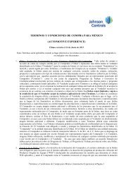


![[PDF] Warren S. Johnson Society of Retirees, Inc.](https://img.yumpu.com/23687624/1/190x245/pdf-warren-s-johnson-society-of-retirees-inc.jpg?quality=85)