LM-1 Digital Air/Fuel Ratio (Lambda) Meter Manual - Innovate ...
LM-1 Digital Air/Fuel Ratio (Lambda) Meter Manual - Innovate ...
LM-1 Digital Air/Fuel Ratio (Lambda) Meter Manual - Innovate ...

Create successful ePaper yourself
Turn your PDF publications into a flip-book with our unique Google optimized e-Paper software.
<strong>LM</strong>-1 <strong>Digital</strong> <strong>Air</strong>/<strong>Fuel</strong> <strong>Ratio</strong> (<strong>Lambda</strong>) <strong>Meter</strong><br />
<strong>Manual</strong><br />
Warning!<br />
The Oxygen Sensor used in this device gets very hot in operation.<br />
Do not touch the hot sensor. Do not let a hot sensor touch a<br />
combustible surface. Do not use the sensor with or near flammable<br />
liquids or gases. Failure to heed these warnings may result in severe<br />
burns, explosions or fires.<br />
When installed in the exhaust, the oxygen sensor MUST be<br />
connected and operating with the <strong>LM</strong>-1 whenever the car is running.<br />
An un-powered oxygen sensor will be quickly damaged when<br />
exposed to hot exhaust gases.<br />
<strong>LM</strong>-1_<strong>Manual</strong>_3.4.doc
1. Overview............................................................................................................................... 2<br />
2. The <strong>LM</strong>-1 Instrument ............................................................................................................ 3<br />
2.1. The <strong>LM</strong>-1 Instrument (Size: 7" x 4" x 1.5")...................................................................... 3<br />
3. First Time Use ...................................................................................................................... 3<br />
4. Installation............................................................................................................................. 4<br />
4.1. Mounting the sensor using a Bung or Exhaust Clamp. .................................................... 4<br />
4.2. How to fabricate a copper heat sink ................................................................................. 6<br />
5. Operation .............................................................................................................................. 6<br />
6. Calibration............................................................................................................................. 7<br />
6.1. Free air calibration ............................................................................................................ 7<br />
6.2. Sensor heater calibration .................................................................................................. 7<br />
6.3. Calibration Schedule......................................................................................................... 7<br />
7. Recording other vehicle data with the <strong>LM</strong>-1 ......................................................................... 8<br />
7.1. Overview ........................................................................................................................... 8<br />
7.2. Recording.......................................................................................................................... 8<br />
8. Remote display of <strong>Lambda</strong> and/or AFR ............................................................................... 9<br />
8.1. Analog <strong>Lambda</strong>/AFR instrument....................................................................................... 9<br />
8.2. Special considerations when installing <strong>LM</strong>-1 permanently in the vehicle......................... 9<br />
9. Programming the <strong>LM</strong>-1....................................................................................................... 11<br />
9.1. Installing the <strong>LM</strong> Programmer Software ......................................................................... 11<br />
Hooking up the <strong>LM</strong>-1 device to the computer............................................................................ 11<br />
9.2. Resetting the calibration data ......................................................................................... 12<br />
9.3. Updating the software (<strong>LM</strong>-1 firmware) .......................................................................... 12<br />
9.4. Programming the analog outputs.................................................................................... 13<br />
9.4.1. Advanced output programming................................................................................ 14<br />
10. Tips, Tricks and Troubleshooting ....................................................................................... 15<br />
10.1. General measurement requirements .......................................................................... 15<br />
10.2. Vehicles with ‘smog-pumps’ ........................................................................................ 15<br />
10.3. Measuring at the tail-pipe ............................................................................................ 15<br />
10.4. Single Cylinder Engines .............................................................................................. 15<br />
10.5. Diesel Engines............................................................................................................. 15<br />
10.6. Reference cell or Pump cell circuit open or shorted errors......................................... 15<br />
10.7. Sensor Timing Errors .................................................................................................. 16<br />
10.8. Other tricks .................................................................................................................. 16<br />
10.9. Analog Output tricks/hints ........................................................................................... 16<br />
11. Advanced Topics ................................................................................................................ 17<br />
11.1. Connecting the <strong>LM</strong>-1 to simulate a narrow band oxygen sensor................................ 17<br />
12. Kit Contents ........................................................................................................................ 18<br />
Appendix A: <strong>LM</strong>-1 Cable Pinouts .................................................................................................20<br />
Appendix B: <strong>LM</strong>-1 Error Codes and Troubleshooting Tips .......................................................... 23<br />
Appendix C: Limited Warranty...................................................................................................... 24<br />
Revision History............................................................................................................................. 25<br />
1. Overview<br />
- 2 -
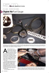
The <strong>LM</strong>-1 is a hand-held instrument used to measure the <strong>Air</strong>/<strong>Fuel</strong> <strong>Ratio</strong> (AFR) or <strong>Lambda</strong> for an<br />
engine. For gasoline-driven engines, the theoretically optimal air fuel ratio is 14.7 pounds of air<br />
for every pound of fuel. At this ratio, theoretically, all available oxygen in the air combines with all<br />
available fuel. This ratio is called the stoichiometric ratio. Stoichiometric for different fuels are as<br />
follows:<br />
Gasoline 14.7<br />
LPG (Propane) 15.5<br />
Methanol 6.4<br />
Ethanol 9.0<br />
CNG 17.2<br />
Diesel 14.6<br />
The measurement <strong>Lambda</strong> is the actual air fuel ratio over the stoichiometric ratio. A <strong>Lambda</strong><br />
measurement of “1” equates to the air fuel ratio of 14.7 (for gasoline engines). When <strong>Lambda</strong> is<br />
less than 1 the engine runs “rich”, i.e., unburned fuel exists in the exhaust stream. If lambda is<br />
greater than 1 the engine runs lean, i.e., free oxygen (0 2 ) is present in the exhaust. Depending on<br />
the engine, maximum power is typically delivered when the engine runs slightly rich (for example<br />
at lambda values of 0.8 to 0.9 for most engines). This instrument provides a means to measure<br />
the actual air fuel ratio or lambda in the engine in operation directly from the exhaust. For this a<br />
special wide-band oxygen sensor is used to measure the lambda value derived from the oxygen<br />
content (or lack thereof) of the exhaust gases.<br />
2. First Time Use<br />
1. Verify that the included 9V battery is installed in the battery compartment on the bottom of the<br />
instrument.<br />
2. Connect the power cable to the <strong>LM</strong>-1 12V Power connector and plug the other end in your<br />
cigarette lighter socket in your car. Note that the 9V battery is for powering the <strong>LM</strong>-1<br />
electronics and display, but it cannot power the oxygen sensor. (The primary purpose for the<br />
9V battery is to power the <strong>LM</strong>-1 when it is connected to a PC for data downloads). You must<br />
have a 12V power supply available to power the oxygen sensor.<br />
Note: The supply voltage to the <strong>LM</strong>-1 must not exceed 16V.<br />
3. Do not connect the sensor yet.<br />
4. Switch the meter on.<br />
The display shows either:<br />
when connected to 12V Power, or .<br />
In the second case, switch the ignition of your car on.<br />
5. Switch the meter off after 10 seconds.<br />
6. Connect the sensor to the sensor interface connector. The sensor must be exposed to air for<br />
the first time calibration.<br />
7. Switch the meter on. The display should show now:<br />
- 3 -
Indicating that the sensor is warming up to its optimum operating temperature. The display shows<br />
what percentage of the temperature is reached and what the battery voltage is that the meter<br />
sees on the power connector. The warm-up period will last for about 30 seconds for a cold<br />
sensor, depending on the sensor type used.<br />
After the sensor is warmed up the meter automatically calibrates the sensor heater controller to<br />
the particular sensor. During this 20-second period the <strong>LM</strong>-1 collects and calculates sensor<br />
specific data required to quickly reach operating temperature in the future. After the first time use<br />
the meter will use these values to regulate the sensor's temperature. During the heater calibration<br />
the display will show:<br />
Counting down to 0.<br />
Note: When using the Bosch Sensors the <strong>LM</strong>-1 may perform multiple calibration passes. This is<br />
normal and need not cause concern. When it completes, continue to step 8.<br />
8. Press the Calibration button.<br />
The meter will now calibrate itself by using air as a reference gas with known oxygen content.<br />
After the calibration period is over (2-3 seconds), the instrument is ready to operate.<br />
To recalibrate you need to hold down the Calibration button for a minimum of 2<br />
seconds.<br />
3. Installation<br />
3.1. Mounting the sensor using a Bung or Exhaust Clamp.<br />
Using a bung is the preferred method for mounting the O 2 sensor for both catalytic and<br />
non-catalytic cars.<br />
On CATALYTIC CONVERTER equipped vehicles:<br />
Bung: Install the oxygen sensor’s bung upstream from the catalytic converter<br />
(a bung and plug is included in the <strong>LM</strong>-1 kit). Any decent muffler or<br />
exhaust shop can do this for you. The wide-band oxygen sensor is then<br />
installed into the bung to take a reading. (Insert the plug into the bung<br />
when not in use). The bung must be installed in the exhaust pipe at<br />
the side or on top, NOT on the bottom of the exhaust pipe. Best<br />
position is between 10:00 and 2:00 position.<br />
……or………<br />
Exhaust Clamp: You may use the optional Exhaust Clamp to mount the O 2 sensor to the<br />
car’s tail pipe when taking readings from cars with catalytic converters<br />
(see below). However, it is recommended instead to use the bung (as<br />
described above) to give you the most accurate reading. Measuring<br />
after the cat will result in leaner-than-reality readings, depending on the<br />
- 4 -
On NON-CATALYTIC converter vehicles:<br />
efficiency of the cat. Some operators of chassis dynos use this method<br />
and roughly “correct” the reading.<br />
Exhaust Clamp: With non-cat cars, you can simply take the reading from the car’s tail<br />
pipe; however, you MUST use the optional Exhaust Clamp to do so. Do<br />
NOT simply insert the O 2 sensor into the tail pipe. Doing so may<br />
damage the sensor and it will certainly not yield accurate<br />
measurements. (The oxygen sensor needs to have its cable exposed<br />
to outside air to yield the most accurate results.)<br />
……or………<br />
Bung: You have the option with non-catalytic cars to also use a Bung as<br />
described above. Use of a bung is the preferred method for mounting<br />
the 0 2 sensor for both catalytic and non-catalytic cars.<br />
On TURBO CHARGED vehicles:<br />
Bung: Install the bung downstream from the turbo before the catalytic<br />
converter. The high exhaust pressure before the turbo interferes with<br />
the lambda measurement and the high exhaust temperatures<br />
encountered there can damage the sensor.<br />
Do NOT install the Bung below the 3 o'clock or 9 o'clock position.<br />
Condensation can form in the exhaust pipe and permanently damage the sensor.<br />
6 o’clock is the absolute worst position to mount the sensor.<br />
Wide band oxygen sensors – like the one shipped with the <strong>LM</strong>-1 – are<br />
designed to work with unleaded gasoline. Using them with leaded gasoline will<br />
significantly reduce the lifespan of the sensor. The reduction is directly<br />
proportional to the metal content of the fuel. In most cases, a wide band sensor<br />
will provide accurate measurements somewhere between 50 hours and 500 hours<br />
with leaded fuel.<br />
WHEN INSTALLED IN THE EXHAUST, THE OXYGEN SENSOR<br />
MUST BE CONNECTED AND OPERATING WITH THE <strong>LM</strong>-1<br />
WHENEVER THE CAR IS RUNNING. AN UN-POWERED OXYGEN<br />
SENSOR WILL BE DAMAGED WHEN EXPOSED TO EXHAUST GAS.<br />
RULE OF THUMB: POWER UP THE OXYGEN SENSOR<br />
IMMEDIATELY AFTER THE ENGINE IS STARTED.<br />
- 5 -
The maximum temperature of the sensor at the bung (the sensor hexagon)<br />
should not exceed 500 o C or 900 o F. If these temperatures are exceeded in your<br />
application you should either install a copper heat sink (instructions below) or the<br />
<strong>Innovate</strong> Motorsports Heat-Sink Bung extender (HBX-1).<br />
The bung extender is recommended for situations where airflow is restricted or<br />
the encountered heat is higher than a heat sink can handle.<br />
3.2. How to fabricate a copper heat sink<br />
Use a 4” x 4” (10cm x 10 cm) sheet of copper sheet metal 14ga (1.5mm) thick. Drill a hole in the<br />
center with the same diameter of the oxygen sensor threads ~3/4” (19mm).<br />
Fold the sides up 45 deg and mount it between the sensor and the bung like you would a big<br />
washer. Orient it such that the sides are exposed to good airflow.<br />
4. Operation<br />
Once the <strong>LM</strong>-1 has been installed and is in place (see Chapter 4: Installation), lambda<br />
measurements can now be taken.<br />
In operation, the meter's display shows:<br />
showing both the current lambda value and air-fuel-ratio. The numeric lambda and air-fuel-ratio<br />
values are averaged over about 0.2-0.3 seconds so that the numbers are more consistent and<br />
easy to read.<br />
If lambda is greater than 6 (for example, in free air), the display will show “—“ for <strong>Lambda</strong>, and<br />
instead of an AFR reading, the percent of oxygen will be shown..<br />
The bar-graph at the bottom shows the actual instant lambda value in 16 steps. The more of the<br />
bar showing, the richer the mixture. The bar at mid-level means a lambda value of 1.0 (AFR of<br />
14.7 for gasoline engines). If the whole bar shows, the actual lambda value is 0.68 or richer (AFR<br />
of 10 or less for gasoline engines). If none of the bar shows the lambda value is 1.32 or leaner<br />
(AFR 19.4 or more for gasoline engines).<br />
- 6 -
5. Calibration<br />
There are two types of calibration for the <strong>LM</strong>-1: free air calibration and sensor heater calibration.<br />
Sensor heater calibration is automatically performed the first time a new sensor is used, while<br />
free air calibration should be executed frequently.<br />
5.1. Free air calibration<br />
To achieve maximum precision, the <strong>LM</strong>-1 and its sensor needs to be recalibrated frequently.<br />
When the measured lambda is greater than 6, the display will show the oxygen content in %. For<br />
free air it should show 20.9%. If the display value is different by more than 0.6%, recalibrate. You<br />
can test the oxygen sensor by breathing on it. The oxygen content of your breath will show.<br />
The sensor MUST be operated in free air for calibration.<br />
If the wide-band sensor is installed in a vehicle, wait 6-8 hours after running the engine so that all<br />
exhaust gas is dissipated from the exhaust tract of the vehicle. Better yet, disengage the oxygen<br />
sensor and expose the sensor to air (away from the exhaust) for calibration purposes:<br />
1. Connect the meter to 12V from the vehicle and switch it on.<br />
2. After the sensor has warmed up, press the 'Calibrate' button for a minimum of 2 seconds.<br />
3. After the calibration is complete, switch the <strong>LM</strong>-1 off and wait for 30 seconds before you start<br />
the car.<br />
The display will show "Free <strong>Air</strong> Calibr." while it calibrates itself. When the calibration procedure is<br />
finished (2-3 seconds), the display returns to normal showing lambda and oxygen content. If the<br />
oxygen content now differs from 20.9% by more than 0.6%, repeat the calibration.<br />
5.2. Sensor heater calibration<br />
If you change the sensor – either with a replacement sensor or a new type of sensor --, the<br />
heater circuit of the <strong>LM</strong>-1 needs to be recalibrated as well. (See steps in chapter 3 'First Time<br />
Use'). The heater calibration data in the <strong>LM</strong>-1 will be reset when the meter is operated from 12V<br />
without a sensor connected for at least 5 seconds. You can force a reset by doing this, and then<br />
recalibrate by turning the unit off, reconnecting the sensor, and turning the unit on.<br />
After the sensor is warmed up the meter automatically calibrates the sensor heater controller to<br />
the particular sensor. During this 20-second period the <strong>LM</strong>-1 collects and calculates sensorspecific<br />
data required to quickly reach operating temperature in the future. During the heater<br />
calibration the display will show:<br />
Counting down to 0.<br />
Note: When using the Bosch Sensors the <strong>LM</strong>-1 may perform multiple calibration passes. This is<br />
normal and need not cause concern. When it completes, continue to a free air calibration. It is<br />
recommended to perform a free air calibration after any time the sensor heater is<br />
recalibrated.<br />
5.3. Calibration Schedule<br />
- 7 -
Normally aspirated daily driver:<br />
- Calibrate before installation of new sensor<br />
- Calibrate new sensor again after 3 month of use<br />
- Thereafter calibrate once a year or every 20,000 miles, whichever comes first<br />
Turbo car, daily driver (tuned rich):<br />
- Calibrate before installation of new sensor<br />
- Calibrate new sensor again after 3 month of use<br />
- Thereafter calibrate twice a year or every 10,000 miles, whichever comes first<br />
Race car<br />
- Calibrate before first installation of new sensor<br />
- Calibrate once per race weekend<br />
Dyno use<br />
- Calibrate a new sensor<br />
- Calibrate every 2-3 days, depending on usage<br />
6. Recording other vehicle data with the <strong>LM</strong>-1<br />
6.1. Overview<br />
The <strong>LM</strong>-1 has the capability to record other vehicle data from other vehicle sensors while driving<br />
so as to compile a complete log of engine data. For example, the optional <strong>LM</strong>A-2 cable provides<br />
input for up to 5 other sensors (RPM plus 4 others) to the <strong>LM</strong>-1 whose data values will be<br />
recorded.<br />
Never connect the Aux inputs to 12 volt or battery power. Connecting the<br />
inputs to sources that generate greater than 5 volts will result in damage to the<br />
<strong>LM</strong>-1.<br />
The <strong>LM</strong>-1 simply records the voltage on each input connection with a resolution of 10 bits (a<br />
precision of 0.00488 Volt). <strong>LM</strong>-1 will record up to 44 minutes of data from all sensors including<br />
lambda. A new value for each sensor is recorded every 0.08192 seconds (roughly 12<br />
times/second). Software to view and analyze recorded data log files is included with your <strong>LM</strong>-1<br />
and can also be downloaded at www.tuneyourengine.com.<br />
6.2. Recording<br />
To record data in the <strong>LM</strong>-1, press the 'Record' button. The <strong>LM</strong>-1 will display a blinking 'R'<br />
between the lambda and AFR/O2 measurements while recording. To stop recording, press the<br />
'Record' button again. Each time you start recording a new record ‘Session’ is created. A total of<br />
44 minutes of data can be recorded in the <strong>LM</strong>-1. If the internal memory of the <strong>LM</strong>-1 is full, the<br />
blinking 'R' will not show when starting a recording session. Instead it will show an 'F' for 'Full' for<br />
a few seconds. To erase all recorded data, press and hold the 'Record' until 'RS' (for ReSet)<br />
shows between lambda and AFR/O2 display.<br />
Use the included LogWorks software package to download recorded data.<br />
To erase all recorded data, press and hold the 'Record' until 'RS' (for ReSet)<br />
shows between lambda and AFR/O2 display.<br />
- 8 -
7. Remote display of <strong>Lambda</strong> and/or AFR<br />
In some applications it may be desirable to mount the <strong>LM</strong>-1 in the engine compartment or under<br />
the dash permanently and monitor the air-fuel data remotely using a dash-mounted instrument.<br />
The <strong>LM</strong>-1 provides two options for that application.<br />
7.1. Analog <strong>Lambda</strong>/AFR instrument.<br />
There are many analog lambda/AFR displays on the market. They are essentially voltmeters for a<br />
voltage between 0 and 1 V and measure the analog voltage of a narrow band oxygen sensor.<br />
Some are true analog instruments while others provide a LED bar. Because of the very limited<br />
sensing range of a narrow band sensor they are essentially useless as true AFR meters. With the<br />
<strong>LM</strong>-1, connecting these meters to the second analog output of the <strong>LM</strong>-1 allows them to be used<br />
as true remote AFR meters, provided the <strong>LM</strong>-1 analog output is programmed to the<br />
characteristics of the used meter. (Note: the <strong>LM</strong>-1’s Analog Out port is a mini-TRS (stereo)<br />
connection which provides two analog outputs, plus a ground.) The <strong>LM</strong>-1's second analog output<br />
is factory programmed to provide a linear output between 1V and 2V for an AFR of 10 to 20,<br />
allowing a digital voltmeter to be used as the AFR display. Any other linear output range between<br />
0 and 5V can be programmed. See chapter 9.6, 'Programming analog outputs' for details.<br />
7.2. Special considerations when installing <strong>LM</strong>-1 permanently in the<br />
vehicle<br />
Do NOT install the 9V battery in the <strong>LM</strong>-1 when installing it permanently in<br />
the vehicle.<br />
In a typical permanent installation the <strong>LM</strong>-1 will be powered by switched 12V from the vehicle<br />
(12V switched on when the ignition key is turned on) while its power switch is permanently on.<br />
Because the <strong>LM</strong>-1 automatically switches to internal battery power when it does not detect 12V,<br />
the internal battery would drain quickly while the vehicle is parked. To avoid this, do not install the<br />
9V battery. The <strong>LM</strong>-1 will function correctly without it and will be able to record as usual. To<br />
download recorded data, follow the alternate steps described in chapter 9.<br />
It is NOT a good idea to connect the <strong>LM</strong>-1 permanently to 12V and switch it on before the vehicle<br />
is started. Depending on the climate and the senor position in the exhaust, condensation water<br />
can form in the exhaust pipes. This condensation water could then be blown by the exhaust<br />
stream against the hot sensor when the car is started. The resulting heat shock can permanently<br />
damage the sensor.<br />
To protect the <strong>LM</strong>-1 when installed permanently it is a good idea to power the <strong>LM</strong>-1 only after<br />
the car is started. The starter motor in some vehicles can create voltage spikes of over 100V<br />
that have the potential to do damage. Although rare, this is a real possibility and the <strong>LM</strong>-1<br />
contains protection circuitry to guard against it. A relay connected as shown below insures that<br />
the <strong>LM</strong>-1 is disconnected while cranking. This reduces further drain on the car battery by the<br />
sensor heater and protects the <strong>LM</strong>-1 against abnormally large voltage spikes.<br />
- 9 -
Connect one terminal of the relay switch and relay coil to switched 12V (number 15 on European<br />
cars). Connect the other switch terminal to the 12V input of the <strong>LM</strong>-1. Connect the other end of<br />
the relay coil to the starter solenoid wire (number 50 on European cars). When the starter<br />
solenoid is operated, the relay will switch off. In running condition, the relay coil current will flow<br />
from 12V through the starter solenoid to ground. The relay coil current is normally far too small to<br />
operate the starter solenoid.<br />
- 10 -
8. Programming the <strong>LM</strong>-1<br />
The <strong>LM</strong>-1 is programmable with the following functionality:<br />
1. Change the relationship between <strong>Lambda</strong> and AFR.<br />
2. Upgrade and change the firmware.<br />
3. Change the output characteristics of the Analog outputs.<br />
4. Download recorded data into a spreadsheet.<br />
5. Graph and analyze the recorded data.<br />
8.1. Installing the <strong>LM</strong> Programmer Software<br />
Put the included CD in your CD-drive on your computer and follow the instructions on screen.<br />
The LogWorks Software will be installed including pre-set directories for log-data and<br />
downloaded software.<br />
The following items will be installed on your hard-drive<br />
1. <strong>LM</strong> Programmer<br />
This is used to program the analog outputs of the <strong>LM</strong>-1, the fuel type used, the sensor<br />
type used, and also allows to ‘reflash’ the firmware of the <strong>LM</strong>-1.<br />
2. LogWorks<br />
This is a comprehensive data logging and analysis package to download and analyze<br />
engine data recorded by the <strong>LM</strong>-1. It also allows real-time logging and display.<br />
3. <strong>Manual</strong>s for all <strong>Innovate</strong> Products<br />
4. Tools<br />
5. Example log files<br />
Hooking up the <strong>LM</strong>-1 device to the computer<br />
- Connect the included serial download cable to a free serial port on your computer.<br />
- With the <strong>LM</strong>-1 turned off, connect the round Mini-DIN8 connector to the serial port of<br />
the <strong>LM</strong>-1.<br />
- Start the <strong>LM</strong> Programmer<br />
- Switch on the <strong>LM</strong>-1 Instrument.<br />
The <strong>LM</strong>-1 display shows:<br />
The <strong>LM</strong>-1 will stay in serial mode until it is switched off, either by its power switch or by<br />
disconnecting 12V if no internal battery is installed.<br />
Your screen should look like this:<br />
- 11 -
On this page you can see the software version of the <strong>LM</strong>-1, which sensor your <strong>LM</strong>-1 uses and<br />
you can change the multiplier to calculate AFR from <strong>Lambda</strong>. A number of different multipliers<br />
are already pre-selectable but you can change it to a custom one for the particular fuel you are<br />
using.<br />
8.2. Resetting the calibration data<br />
Press the Reset Calibration button if you want to reset all calibration data in the <strong>LM</strong>-1.<br />
This will clear all calibration data of the <strong>LM</strong>-1.<br />
8.3. Updating the software (<strong>LM</strong>-1 firmware)<br />
Click the 'Update Firmware' in the main page to upgrade to the latest firmware for the <strong>LM</strong>-1.<br />
Firmware for the <strong>LM</strong>-1 has the extension dld. You can download the latest firmware and<br />
software (<strong>LM</strong> Programmer and LogWorks) from the <strong>Innovate</strong>! Motorsports web-site at<br />
http://www.tuneyourengine.com<br />
If your computer crashes during a firmware upgrade, the <strong>LM</strong>-1 has a recovery mechanism where<br />
it will be able to retry the download again and not be disabled by half loaded firmware. Switch the<br />
<strong>LM</strong>-1 off and on again and then try to restart the <strong>LM</strong>1 Manager software. The recovery<br />
mechanism is designed to be able to recover 99.9% of the time. While we don’t anticipate this<br />
occurring, it is possible that the <strong>LM</strong>-1 will not recover correctly and may need to be serviced at<br />
our factory. If you suspect this is the case, contact <strong>Innovate</strong> support.<br />
- 12 -
8.4. Programming the analog outputs<br />
Select one of the Analog output tabs. The Analog output page looks like this:<br />
This shows the analog output voltages versus <strong>Lambda</strong> for one of the two analog outputs. The<br />
graph display is automatically scaled to the selected voltages. For each output you can specify a<br />
minimum and maximum lambda value and the associated voltages. Below the minimum and<br />
above the maximum lambda values the output voltages stay constant at the associated<br />
programmed voltage.<br />
By selecting the ‘use <strong>Air</strong>-<strong>Fuel</strong>-<strong>Ratio</strong>’ button you can program the curve by AFR instead of<br />
<strong>Lambda</strong>.<br />
This does not change the programming, only the representation of the data. When<br />
programming by AFR the <strong>LM</strong> Programmer converts the number to <strong>Lambda</strong> before<br />
programming the <strong>LM</strong>-1.<br />
Click the Program button to download the new data into the <strong>LM</strong>-1.<br />
As factory programmed the first output simulates a typical narrow band oxygen sensor. The<br />
second output is programmed to output between 1.0 V for an AFR of 10 (gasoline) and 2.0V for<br />
an AFR of 20. This allows to connect it to a digital voltmeter or panel meter (0.2V input) to show<br />
directly AFR. Other curves of course are easily programmable<br />
- 13 -
8.4.1. Advanced output programming<br />
Note:<br />
The advanced analog output settings are only available from <strong>LM</strong>-1 firmware version 1.33b on. If<br />
your <strong>LM</strong>-1 has an earlier version of firmware, you can upgrade to later versions by downloading it<br />
from www.tuneyourengine.com .<br />
The normal state of the analog outputs is to update the outputs every time the <strong>LM</strong>-1 takes a new<br />
measurement. The <strong>LM</strong>-1 is fast enough to distinguish individual pockets of exhaust gas. For<br />
many applications this will be too fast. The advanced programming allows to set the analog out<br />
update speed.<br />
Press the “Advanced button” to set the advanced analog out settings. The following dialog box<br />
will appear:<br />
When setting the <strong>LM</strong>-1 to the slower response speed settings the measured mixture data will be<br />
averaged over the response time setting before being output.<br />
You can also specify what output voltage is visible on the analog outputs during warmup of the<br />
sensor and during error conditions.<br />
The ‘High Impedance’ setting allows to specify that the analog outputs do not drive the output<br />
during warmup or error condition. They will be free floating. This is important for more closely<br />
simulating a narrow band sensor. Many EFI systems monitor the impedance of a narrow band<br />
sensor during engine warmup to determine sensor readiness. A narrow band sensor that’s too<br />
cold will have a high impedance.<br />
Note:<br />
The high impedance setting will always apply to both analog outputs of the <strong>LM</strong>-1.<br />
They can’t be set to high impedance individually.<br />
- 14 -
9. Tips, Tricks and Troubleshooting<br />
9.1. General measurement requirements<br />
The <strong>LM</strong>-1 measures the air-fuel-ratio by measuring the amount of oxygen in the exhaust (for lean<br />
conditions) or the amount of unburned or partially burned fuel (for rich conditions). You should<br />
correct for the following in order to get optimum results from the <strong>LM</strong>-1<br />
1) An exhaust leak will allow oxygen to enter the exhaust stream and therefore will<br />
measure leaner than the engine is actually running. For correct measurement, airleaks<br />
in the exhaust MUST be prevented under all circumstances.<br />
2) Missing ignitions (where the air-fuel mixture does not ignite) also pump unburned<br />
oxygen into the exhaust and cause the <strong>LM</strong>-1 to measure lean.<br />
3) The only circumstance where the <strong>LM</strong>-1 will measure richer than the engine is running<br />
is if the pressure in the exhaust tract is excessive (and the engine is running on the<br />
rich side to begin with).<br />
9.2. Vehicles with ‘smog-pumps’<br />
Older fuel injected vehicles with a ‘smog-pump’ actually inject air into the exhaust stream to aid<br />
their catalytic converter in the burn-up of unburned or partially burned fuels. This additional air will<br />
make the exhaust look leaner than the engine is running. For an accurate measure, install the<br />
<strong>LM</strong>-1 sensor up-stream of the outputs of the smog-pump. If this is not possible, temporarily<br />
disable the smog-pump by removing its drive belt.<br />
9.3. Measuring at the tail-pipe<br />
On non-catalytic converter equipped vehicles it is possible to measure the air-fuel-ratio at the tailpipe.<br />
It is highly recommended to use the optional <strong>LM</strong>-1 Exhaust Clamp. Without it too much<br />
outside air may enter the exhaust, especially at idle, to prevent correct measurements and<br />
leading to a lean measurement. Sticking the sensor itself into the exhaust pipe can yield<br />
inconsistent results because the sensor will not have outside air available as a reference gas and<br />
its reaction time becomes so slow that the <strong>LM</strong>-1 will report a sensor timing error. The oxygen<br />
sensor needs to have the back part of the sensor (where the wires enter the sensor) exposed to<br />
outside air.<br />
9.4. Single Cylinder Engines<br />
These kinds of engines are difficult to measure at the tail-pipe. The oscillations of the exhaust<br />
gas are so large that a lot of outside air enters the exhaust and prevents correct measurement.<br />
Sometimes it helps to just wrap a piece of heat resistant cloth around the exhaust clamp to<br />
prevent outside air from entering the exhaust.<br />
9.5. Diesel Engines<br />
Diesel Engines and gas turbines run at wide open throttle at all times. They do not have a throttle<br />
but regulate power by the amount of injected fuel. The <strong>LM</strong>-1 can still be used, but measurements<br />
at idle will read as lean.<br />
9.6. Reference cell or Pump cell circuit open or shorted errors<br />
- 15 -
Under some rare circumstances it is possible that the heater calibration data in the <strong>LM</strong>-1 can<br />
become partially destroyed. This can manifest in the above-mentioned errors. Follow the steps in<br />
chapter 3 ‘First time use’ to reset the heater calibration data.<br />
9.7. Sensor Timing Errors<br />
These errors are typically encountered when the sensor does not have outside air available as<br />
reference gas. If you encounter this error, restart the <strong>LM</strong>-1 and operate the sensor in free air. If<br />
you still encounter this error, the sensor may be bad and needs to be replaced.<br />
Replacement sensors are available from your nearest VW dealer under the VW part-number<br />
021-906-262-B or direct from <strong>Innovate</strong> Motorsports.<br />
Sensor timing errors are also common when the sensor overheats. Relocate the sensor further<br />
downstream in the exhaust, install a heat sink or Heat-Sink Bung extender (HBX-1).<br />
Sometimes it’s possible to encounter Error 08 when the exhaust gas suddenly gets too rich.<br />
Normally the <strong>LM</strong>-1 will display a ‘too rich’ indication if the exhaust gas is too rich. If the mixture<br />
gets rich very suddenly, the <strong>LM</strong>-1 cannot distinguish between a too rich condition and a sensor<br />
timing error.<br />
9.8. Other tricks<br />
The <strong>LM</strong>-1 has two different functions for the record and calibration button when it runs off it’s<br />
internal 9V battery (12V disconnected):<br />
1. Calibration button:<br />
Shows firmware version and sensor type used.<br />
2. Record button<br />
Pressing the record button with an RPM converter connected shows the RPMs read by the RPM<br />
converter.<br />
Note:<br />
If the RPM converter is programmed for RPMs greater than 10230 (see RPM converter manual),<br />
the shown RPM’s will be ½ of the real RPMs.<br />
9.9. Analog Output tricks/hints<br />
Very often there is a ground offset between the device that receives the analog output voltage<br />
and the <strong>LM</strong>-1. Both devices reference different grounds and therefore see different voltages. So<br />
to compensate for the ground offsets the analog output voltage points have to be shifted by the<br />
ground offsets. To measure what the real ground offset is, you can program the analog outputs<br />
temporarily to output a flat line voltage by entering the same voltage in both fields for the two<br />
analog out programming points. This way the analog output voltage will be fixed, independent of<br />
current AFR and can therefore be measured and compensated for easily<br />
Note:<br />
The analog outputs are NOT designed to power other devices or sensors.<br />
So using the flat-line setting at 5V and expecting to power a sensor from it<br />
will not work and can damage the <strong>LM</strong>-1.<br />
- 16 -
10. Advanced Topics<br />
10.1. Connecting the <strong>LM</strong>-1 to simulate a narrow band oxygen<br />
sensor.<br />
It is possible to install the wide-band sensor in place of the OEM oxygen sensor. In this case the<br />
meter's analog output signal will replace the OEM oxygen sensor's signal to the fuel injection<br />
computer. EFI equipped cars typically incorporate a narrow band oxygen sensor. These sensors<br />
are typically 1, 2, 3 or 4 wire sensors.<br />
The analog output connector of the <strong>LM</strong>-1 can simulate the operation of a narrow band sensor<br />
while the wide-band oxygen sensor is installed in place of the OEM narrow-band sensor. Factory<br />
equipped Analog output 1 of the <strong>LM</strong>-1 is programmed to simulate a narrow band sensor. Some<br />
vehicles are equipped with oxygen sensors that do not produce an output voltage but change<br />
their resistance depending on exhaust gas content. These sensors cannot be simulated. They<br />
are used in less than 1% of all vehicles. Refer to your vehicles specifications if you think that<br />
your vehicle may be in this category. The same is true for vehicles already factory equipped with<br />
a wide-band oxygen sensor. These cannot be simulated either.<br />
Some EFI-computers will create a fault when the heater power wires of the oxygen sensor are<br />
disconnected. In this case mount the old oxygen sensor in a safe place (but not necessarily in the<br />
exhaust) and connect the heater wires to it to keep the EFI-computer happy.<br />
hot.<br />
Be careful where you mount the stock sensor, as heated sensors will get<br />
To connect the <strong>LM</strong>-1 to the EFI-computer, first determine what kind of narrow band sensor is<br />
used, then follow the instructions below (you will need a digital multimeter to determine correct<br />
OEM sensor wires):<br />
a. Vehicle has a 1-wire sensor:<br />
Wire analog output 1 directly to the wire.<br />
b. Vehicle has a 2-wire sensor:<br />
While the engine is off determine which of the 2 wires has a low resistance between the wire and<br />
the sensor body. This is the heater power for the sensor. Wire analog output 1 directly to the<br />
other wire. Leave the heater power wire unconnected but make sure it cannot ground itself or see<br />
above.<br />
c. Vehicle has a 3-wire sensor:<br />
Typically the 3 wires are: heater power, Ground, and sensor element connection.<br />
Generally they have 1 black wire and 2 white wires. Connect the black wire from the EFI<br />
computer to analog output 1 of the meter. Leave the other wires unconnected but make sure they<br />
cannot contact any metal parts or see above. If the wiring colors are different, then heater power<br />
can simply be determined by measuring the voltage on the wires when the engine is running. The<br />
wire showing 12V or more is the heater power. The sensor element connection voltage fluctuates<br />
around 0.45V when the car is warmed up. Wire analog output 1 directly to this wire. The Ground<br />
connection has low resistance to chassis ground (less than 1 Ohm). Measure while the engine is<br />
off.<br />
d. Vehicle has a 4-wire sensor<br />
Typically the 4 wires are: heater power, heater ground, sensor ground, and sensor element<br />
connection. Proceed as for the 3-wire sensor.<br />
- 17 -
11. Kit Contents<br />
Sensor Cable (10 ft)<br />
P/N: 3738<br />
Power Cable<br />
P/N 3740<br />
9 Volt Battery<br />
Quick Start Guide<br />
<strong>LM</strong>-1 Basic Kit P/N: 3723<br />
Software CD<br />
- 18 -<br />
Bung/Plug Kit<br />
P/N 3735<br />
Analog Output Cable<br />
P/N: 3730<br />
Serial Cable<br />
P/N: 3741<br />
02 Sensor<br />
P/N 3737<br />
<strong>LM</strong>-1 <strong>Meter</strong>
<strong>LM</strong>-1 RPM Kit P/N: 3724<br />
(Refer to <strong>LM</strong>-1 Basic Kit (3723) for other items included in this kit.)<br />
<strong>LM</strong>A-2 RPM Converter RPM Converter<br />
Program Cable<br />
Programmer Cable<br />
P/N: 3746<br />
<strong>LM</strong>A-3 AuxBox<br />
<strong>LM</strong>-1 AuxBox Kit P/N: 3756<br />
(Refer to <strong>LM</strong>-1 Basic Kit (3723) for other items included in this kit.)<br />
- 19 -<br />
<strong>LM</strong>A-3 to <strong>LM</strong>-1 Cable<br />
P/N: 3748<br />
Accessory Kit<br />
P/N: 3749<br />
Terminator Plug<br />
P/N: 3750
Appendix A: <strong>LM</strong>-1 Cable Pinouts<br />
A1. Serial Interface (Mini-DIN8 female connector)<br />
Serial Interface:<br />
19.2 kBaud<br />
8 Data bits<br />
1 Stop bit<br />
no parity<br />
no hardware handshaking<br />
Pin Assignments<br />
<strong>Lambda</strong> <strong>Meter</strong><br />
Mini-DIN8 Signal Computer DB-9 Computer DB-25<br />
1 n/c n/c n/c<br />
2 CTS 8 5 Connected to +5V<br />
3 RxD 2 3<br />
4 GND 5 7<br />
5 TxD 3 2<br />
6 GND 5 7<br />
7 n/c n/c n/c<br />
8 n/c n/c n/c<br />
A2. Aux Input Connector (Mini-DIN7 female connector)<br />
Note: Connect to signal of maximum 5V only.<br />
Serious damage to meter and/or sensor may result if connected to signals of more than 5V<br />
amplitude.<br />
Pin Assignments<br />
<strong>Lambda</strong> <strong>Meter</strong><br />
Mini-DIN7 Signal<br />
- 20 -
1 +5V from <strong>Meter</strong><br />
2 Sensor 5 Input<br />
3 Sensor 1 Input<br />
4 Sensor 4 Input<br />
5 Sensor 2 Input<br />
6 Sensor 3 Input<br />
7 Ground<br />
A3. Analog Outputs (3.5mm Stereo connector)<br />
Stereo plug shown<br />
Pin Assignments<br />
<strong>Lambda</strong> <strong>Meter</strong><br />
Stereo Signal<br />
1 Analog output 1<br />
2 Analog output 2<br />
3 Ground<br />
A4. Sensor Interface Connector (Standard DIN-5 female)<br />
Pin Assignments<br />
<strong>Lambda</strong> <strong>Meter</strong> Signal Wire Colors<br />
Bosch LSU4.2<br />
1 Pump+ red<br />
2 Sens+ black<br />
3 Heater - white<br />
4 Pump-/Sens- yellow<br />
5 Heater + gray<br />
A5. Power Connector (3.5mm power connector female)<br />
- 21 -
- 22 -
Appendix B: <strong>LM</strong>-1 Error Codes and Troubleshooting Tips<br />
Error<br />
Code<br />
Error Message Likely Root Cause Fix<br />
Error 1 Heater circuit shorted 1. Short in cable<br />
1. Repair/replace cable.<br />
2. Short in sensor<br />
2. Replace sensor.<br />
Error 2 Heater circuit open 1. Damaged cable or DIN 1. Verify DIN connector is fully<br />
connector not fully seated seated into unit. Repair/replace<br />
cable.<br />
Error 3 Pump cell circuit shorted 1. Short in cable<br />
1. Repair/replace cable.<br />
2. Short in sensor<br />
2. Replace sensor.<br />
3. Sensor heater calibration 3. Perform sensor heater<br />
incorrect<br />
recalibration.<br />
4. Sensor overheating 4. Move your sensor bung as<br />
5. EGT >1700º F<br />
far downstream as possible<br />
OR add a heatsink to isolate<br />
the sensor from the pipe.<br />
5. “”<br />
Error 4 Pump cell circuit open 1. Damaged cable or DIN 1. Verify DIN connector is fully<br />
connector not fully seated seated into unit. Repair/replace<br />
2. Sensor heater calibration cable.<br />
incorrect<br />
2. Perform complete heater<br />
calibration (not just free air<br />
calibration). See section 4.6<br />
Error 5 Reference cell circuit 1. Short in cable<br />
1. Repair/replace cable.<br />
shorted<br />
2. Short in sensor<br />
2. Replace sensor.<br />
Error 6 Reference cell circuit open 1. Damaged cable or DIN 1. Verify DIN connector is fully<br />
connector not fully seated seated into unit. Repair/replace<br />
2. Damaged Sensor<br />
cable.<br />
2. Replace sensor<br />
Error 7 General System error Typically a software error Reboot <strong>LM</strong>-1. Re-flash unit if<br />
(typically a software error).<br />
necessary.<br />
Error 8 Sensor Timing error 1. Sensor overheating. 1. a. Perform sensor heater<br />
(typically a damaged (The Bosch LSU4.2 is rated recalibration; b. Move your<br />
sensor).<br />
to operate at a sensor<br />
sensor bung as far<br />
housing temperature of < 900 downstream as possible. Right<br />
degrees (measured at the before the cat, or 2-3 feet from<br />
bung) for maximum accuracy the end of the tailpipe are good<br />
and control. When this<br />
locations; c. Add a heatsink to<br />
operating temperature range isolate the sensor from the<br />
is exceeded, the sensor can pipe. The HBX-1 is an<br />
no longer be accurately available accessory.<br />
controlled. )<br />
2. Sensor is damaged<br />
2. Replace sensor.<br />
Error 9 Supply Voltage too low Supply voltage too low for Bypass cigarette-adapter,<br />
sensor regulation<br />
recharge battery, or improve<br />
electrical system<br />
- 23 -
Appendix C: Limited Warranty<br />
LIMITED WARRANTY<br />
<strong>Innovate</strong> stands behind the quality of its products. <strong>Innovate</strong> makes the following warranty to<br />
purchasers of its products: All new <strong>Innovate</strong> products carry a six-month warranty from the date of<br />
purchase. If proof of purchase cannot be provided, warranty will be determined by date of<br />
manufacture.<br />
When Warranty Void<br />
This warranty shall terminate and <strong>Innovate</strong> shall have no obligation pursuant to it if (i) your<br />
<strong>Innovate</strong> product has been modified or repaired in a manner not previously authorized by<br />
<strong>Innovate</strong> in writing, (ii) the identification markings on your <strong>Innovate</strong> product have been removed,<br />
defaced, or altered; (iii) your <strong>Innovate</strong> product was subjected to accident, abuse, shipping<br />
damage, or improper use; (iv) your <strong>Innovate</strong> product was not used or configured as specified in<br />
the product manual; or (v) your <strong>Innovate</strong> product was subjected to operating conditions more<br />
severe than those specified in the product manual.<br />
Exclusions From This Warranty<br />
Oxygen Sensors are excluded from this warranty.<br />
Repairs Under This Warranty<br />
In the unlikely event that your <strong>Innovate</strong> hardware product should prove defective during the<br />
warranty period, contact <strong>Innovate</strong> Customer Support for a return material authorization (RMA) at<br />
949-502-8400. Products returned for service must be securely packed to prevent damage and<br />
shipped charges pre paid, along with proof of purchase and the return material authorization<br />
number, to the <strong>Innovate</strong> repair location as instructed by Customer Service. <strong>Innovate</strong> within a<br />
reasonable amount of time from its receipt of your product so shipped, will ship to you, at its<br />
option, the repaired product or a new or reconditioned product of comparable or greater specified<br />
functionality. All repaired or replacement products shall be warranted for the remainder of the<br />
original product warranty.<br />
Disclaimer<br />
INNOVATE MAKES NO OTHER EXPRESS OR IMPLIED WARRANTY WITH RESPECT TO<br />
YOUR INNOVATE PRODUCT OTHER THAN THE LIMITED WARRANTY SET FORTH ABOVE.<br />
No <strong>Innovate</strong> dealer, agent, or employee is authorized to make any modification, extension, or<br />
addition to this warranty, unless enforceable or unlawful under applicable law, INNOVATE<br />
DISCLAIMS ALL IMPLIED WARRANTIES, INCLUDING THE IMPLIED WARRANTIES OF<br />
MERCHANTABILITY, NONINFRINGEMENT, AND FITNESS FOR A PARTICULAR PURPOSE,<br />
AND THE LIABILITY OF INNOVATE, IF ANY, FOR DAMAGES RELATING TO ANY<br />
ALLEGEDLY DEFECTIVE PRODUCT SHALL UNDER ANY TORT, CONTRACT, OR OTHER<br />
LEGAL THEORY BE LIMITED TO THE ACTUAL PRICE PAID FOR SUCH PRODUCT AND<br />
SHALL IN NO EVENT INCLUDE INCIDENTAL, CONSEQUENTIAL, SPECIAL, OR INDIRECT<br />
DAMAGES OF ANY KIND EVEN IF INNOVATE IS AWARE OF THE POSSIBILITY OF SUCH<br />
DAMAGES. Some states do not allow limitations on how long an implied warranty lasts or the<br />
exclusion or limitation of incidental or consequential damages, so the above limitations or<br />
exclusions may not apply to you.<br />
- 24 -
Revision History<br />
1.0 – 5/12/03<br />
Initial release<br />
1.1- 5/14/03<br />
Corrected misc. errata.<br />
2.0 – 6/15/03<br />
Complete revision and update, incl. sections 6, 9, 10, 11<br />
2.1 – 6/20/03<br />
Corrected misc. errata.<br />
2.2 – 6/21/03<br />
Reformatting of TOC.<br />
2.3 – 6/25/03<br />
Corrected/updated Appendix B<br />
2.4 – 6/26/03<br />
Added Appendix D<br />
2.5 – 7/2/03<br />
Corrected/updated programming section (Section 9).<br />
5.6 - 7/9/03<br />
Updated photos<br />
5.7 - 7/23/03<br />
Update included devices list (Section 2.1).<br />
Added Warning at first page and Installation section (Section 4.1).<br />
Update Analog out programming text and screenshot (Section 9.6).<br />
Update <strong>LM</strong>D display (Section A.5).<br />
Update Serial Display Section (Section 11.2).<br />
2.8 - 9/03/03<br />
Update copy after the screenshot of the Data Logger Configuration (Section 9.7)<br />
Update photos and copy for Analog Output Cable (Appendix A1)<br />
Update copy for Analog Outputs (Appendix B3)<br />
2.9 - 1/15/04<br />
Corrected section B2- Aux. Input wiring<br />
Corrected various errata<br />
3.0 - 3/30/04<br />
Update section 4.1 and Appendix B<br />
Removed Appendix A<br />
3.1 – 09/23/05<br />
Updated TOC<br />
- 25 -
3.2 – 03/16/06<br />
Added Calibration Schedule<br />
3.3 – 06/08/06<br />
Updated Tips and Tricks.<br />
Removed sensor support<br />
3.4 – 05/02/07<br />
Added Kit Contents Section<br />
- 26 -