Solenoid Valves, Pneumatic Cylinders, Fittings, Air Treatment - fidemar
Solenoid Valves, Pneumatic Cylinders, Fittings, Air Treatment - fidemar
Solenoid Valves, Pneumatic Cylinders, Fittings, Air Treatment - fidemar

You also want an ePaper? Increase the reach of your titles
YUMPU automatically turns print PDFs into web optimized ePapers that Google loves.
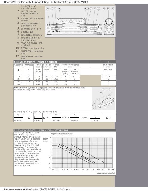
<strong>Solenoid</strong> <strong>Valves</strong>, <strong>Pneumatic</strong> <strong>Cylinders</strong>, <strong>Fittings</strong>, <strong>Air</strong> <strong>Treatment</strong> Groups - METAL WORK<br />
1.<br />
CYLINDER HEAD:<br />
aluminium alloy<br />
2. JACKET: profiled<br />
anodized aluminium<br />
alloy<br />
3. PISTON GASKET: NBR or<br />
Viton®<br />
4. CENTRAL ELEMENT:<br />
aluminium alloy<br />
5. SCRAPER: Delrin 500<br />
6. O-RING: NBR<br />
7. BULL RING: Hostaform<br />
8. CUSHIONING CONE:<br />
aluminium alloy<br />
9. STATIC O-RINGS: NBR<br />
or Viton®<br />
10. PISTON: aluminium alloy<br />
11. OUTER STRIP: stainless<br />
steel<br />
12. INNER STRIP: stainless<br />
steel<br />
DIMENSIONAMENTO - FORZE E MOMENTO ø<br />
Alesaggio Interasse Forza<br />
effettiva<br />
ø Y F a 6<br />
bar (N)<br />
Corsa di<br />
amm.zo<br />
Carico<br />
Max<br />
(mm) L(N) Ma<br />
longitud<br />
(Nm)<br />
Momento flettente<br />
max<br />
Mr<br />
trasvers.<br />
(Nm)<br />
M.torcente<br />
max<br />
Mv (Nm)<br />
16 9 110 15 129 4 0.3 0.5<br />
25 14 250 21 300 15 1 3<br />
32 18 420 26 450 30 2 4<br />
40 22 640 32 750 60 4 8<br />
NB: When the cylinder is subjected simultaneously to torque and force, it is<br />
advisable to keep to the following equations.<br />
Ma = F x ha Mr = L x hv + G x hr Mv = F x hv<br />
Mv<br />
Mv<br />
L<br />
Mv max<br />
<<br />
L max<br />
< 1;<br />
Mv max<br />
+0.22 x<br />
DIAGRAMMA VELOCITA' - CARICO MAX AMMORTIZZABILE<br />
For the cylinder to reach the<br />
end-of-stroke position<br />
without intense or repeated<br />
impact which would damage<br />
it, it is necessary to annul<br />
the kinetic energy of the<br />
moving mass and the work<br />
generated. The maximum<br />
cushionable load depends on<br />
the traversing speed and the<br />
absorption of the air buffer<br />
supplied standard with the<br />
various cylinders. The<br />
diagram shows the speeds<br />
and cushionable mass for<br />
the various diameters at a<br />
pressure of 6 bar.<br />
http://www.metalwork.it/eng/cilc.html (2 of 3) [8/3/2001 03:26:32 p.m.]<br />
Mv<br />
Mv max<br />
+ 0.4<br />
L<br />
L max<br />
< 1