A320 Operating Manual - Delta Virtual Airlines
A320 Operating Manual - Delta Virtual Airlines
A320 Operating Manual - Delta Virtual Airlines

You also want an ePaper? Increase the reach of your titles
YUMPU automatically turns print PDFs into web optimized ePapers that Google loves.
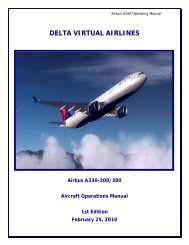
DELTA VIRTUAL AIRLINES<br />
Airbus <strong>A320</strong><br />
Aircraft Operations <strong>Manual</strong><br />
First Edition<br />
August 31, 2009
Table of Contents<br />
Airbus 320 <strong>Operating</strong> <strong>Manual</strong><br />
Welcome ................................................................................................................... 1<br />
History and Overview ................................................................................................. 2<br />
Powerplants .............................................................................................................. 4<br />
SNECMA CFM56 ..................................................................................................... 4<br />
IAE V2500 ............................................................................................................. 4<br />
Aircraft Specifications ................................................................................................. 5<br />
Cockpit Checkout ....................................................................................................... 6<br />
FS9 MAIN (CAPTAIN’S) PANEL ................................................................................ 6<br />
FS9 OVERHEAD PANEL ........................................................................................... 7<br />
FS9 CENTER PEDESTAL VIEW ................................................................................. 9<br />
FSX MAIN (CAPTAIN’S) PANEL .............................................................................. 10<br />
FSX OVERHEAD PANEL- ....................................................................................... 13<br />
FSX CENTER PEDESTAL VIEW .............................................................................. 14<br />
Tutorial-How to Fly the <strong>A320</strong> .................................................................................... 15<br />
Transitioning to an Airbus 320 .............................................................................. 15<br />
<strong>A320</strong> FLIGHT DECK FAMILIARIZATION ................................................................. 16<br />
Flying the aircraft – Tutorial ..................................................................................... 24<br />
Fuel Planning and Weight and Balance ...................................................................... 30<br />
Checklists ................................................................................................................ 31<br />
Flight Deck Preparation ........................................................................................ 31<br />
At Gate Parked-Before Engine Start ....................................................................... 31<br />
Engine Start......................................................................................................... 32<br />
After Engine Start ................................................................................................ 32<br />
Taxi .................................................................................................................... 32<br />
Before Takeoff ..................................................................................................... 33<br />
Takeoff - Cleared or Taxi into position & hold ........................................................ 33<br />
Cruise ................................................................................................................. 33<br />
Descent ............................................................................................................... 34<br />
Approach ............................................................................................................. 34<br />
Landing ............................................................................................................... 34<br />
After Landing (When clear of the runway) ............................................................. 35<br />
At the Gate / Shutdown ........................................................................................ 35<br />
Crew Briefings ......................................................................................................... 36<br />
Takeoff ............................................................................................................... 36<br />
Landing ............................................................................................................... 36<br />
Crew Announcements........................................................................................... 37<br />
Appendix – <strong>Operating</strong> Information ............................................................................ 38<br />
Taxi Speeds: ........................................................................................................ 38<br />
Typical V Speeds .................................................................................................. 38<br />
Climb Profile ........................................................................................................ 38<br />
i
ii<br />
Airbus 320 <strong>Operating</strong> <strong>Manual</strong><br />
Standard Climb Rates ........................................................................................... 38<br />
Descent Rate ....................................................................................................... 38<br />
Approach/Landing Speed Profile............................................................................ 39<br />
Flap Speeds ......................................................................................................... 39<br />
Acknowledgements and Legal Stuff ........................................................................... 40
Welcome<br />
Airbus 320 <strong>Operating</strong> <strong>Manual</strong><br />
Welcome to the <strong>Delta</strong> <strong>Virtual</strong> <strong>Airlines</strong>’ Airbus <strong>A320</strong> Aircraft <strong>Operating</strong> <strong>Manual</strong><br />
(AOM).<br />
The AOM is based upon the DVA Fleet Installer. We are always seeking to<br />
improve the accuracy of the AOM. Should you have questions about the specifics<br />
of this airplane or this manual, you should create a help desk issue at our<br />
website, www.deltava.org<br />
Should you have questions about aviation in general, creating a help desk issue<br />
is the best course of action to take. The training department and the flight<br />
academy personnel, who will do their best to answer your questions, will address<br />
these.<br />
If you are new to flying and would like to learn training that is modeled after real<br />
world training, you can sign up for flight instruction in the DVA Flight Academy.<br />
PAGE 1
History and Overview<br />
Airbus 320 <strong>Operating</strong> <strong>Manual</strong><br />
Despite the conventional wisdom holding Boeing and Airbus airliners as very<br />
different, a close examination of the Airbus <strong>A320</strong> family will lead one to believe<br />
that these often-cited differences are merely skin deep. The development of the<br />
<strong>A320</strong> and its siblings in the 1980’s and 1990’s is in many ways a repetition of the<br />
developments and features that led Boeing to jetliner dominance two decades<br />
earlier.<br />
After seeing the success of its early A300 and A310 wide-bodied airliners, Airbus<br />
Industries decided to target the 115-185 passenger market dominated by<br />
Boeing’s 727 and to compete with the B737 family and B757-200. The <strong>A320</strong><br />
program was launched in March 1984 with JAA certification for the <strong>A320</strong>-100<br />
awarded in early 1988 with certification for the definitive <strong>A320</strong>–200 variant<br />
following in November of that year. FAA approval for both models was awarded<br />
in December of 1988.<br />
What set the <strong>A320</strong> apart from its predecessors and made it a revolutionary<br />
aircraft were its extensive use of composite materials and full “fly-by wire” flight<br />
controls. While both were used before in commercial jetliners (composites in the<br />
A310 and “fly-by wire” in the Concorde), the <strong>A320</strong> took both to new levels in the<br />
quest to develop the “ultimate profit maker,” as Airbus called its new aircraft.<br />
Even for pilots accustomed to newer glass cockpits, entering the <strong>A320</strong> flight deck<br />
for the first time is an experience. There is no yoke – only a small joystick on the<br />
side (the “side stick”) and instead of conventional instruments, the pilots have a<br />
variety of CRT and LCD screens that can convey a vast multitude of aircraft<br />
information.<br />
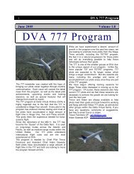
The “fly-by wire” system<br />
translates all pilot control<br />
inputs into electronic<br />
signals that are passed to<br />
the flight controls using<br />
four redundant systems.<br />
Because there is no direct<br />
linkage between the<br />
cockpit controls and the<br />
control surfaces, computers can monitor the flight and prevent potentially<br />
hazardous situations such as stalls, excessive bank and dangerous over-speeds<br />
PAGE 2
Airbus 320 <strong>Operating</strong> <strong>Manual</strong><br />
from occurring, as well as flying the aircraft in autopilot mode in a far more<br />
efficient and precise manner than any human pilot.<br />
As mentioned above, Airbus took a page out of Boeing’s book and emulated the<br />
American manufacturer in two critical ways. First, they created a number of <strong>A320</strong><br />
variants (the 319, 321 and now the “Baby Bus” 318) in different sizes to meet<br />
different route densities, just like Boeing has done with the different 737<br />
variants.<br />
Second, Airbus took the pioneering Boeing practice of aircraft commonality and<br />
took it to new levels. Decades ago, Boeing took many of the fuselage parts of<br />
the 707 (most visibly, the nose) and used them on their 727 and 737 airliners –<br />
greatly simplifying manufacturing and maintenance. Airbus did the same thing,<br />
with a large variety of parts and especially the flight deck, which is shared<br />
between all modern Airbus aircraft from the A318 all the way to the giant A340-<br />
600. This has resulted in a dramatic reduction in training costs, from reduced<br />
simulator counts to shorter type conversion times for flight crews. In early 1994,<br />
the FAA approved a common type rating on the <strong>A320</strong> and A321 without further<br />
training, meaning that a pilot qualified to operate the <strong>A320</strong> was fully qualified to<br />
operate the A321 without any additional training.<br />
Today, the <strong>A320</strong> remains at the top of the list as Airbus’ best-selling aircraft with<br />
6,313 ordered and 3,754 delivered as of January 31 st<br />
, 2009.<br />
PAGE 3
Powerplants<br />
Airbus 320 <strong>Operating</strong> <strong>Manual</strong><br />
All aircraft in the <strong>A320</strong> family can be equipped with either the CFM56 or the<br />
IAE V2500. It is interesting to note that both engines are the product of<br />
collaboration between famous names in the jet engine industry – CFM is owned<br />
by France’s SNECMA and General Electric, while IAE is a joint venture between<br />
Pratt & Whitney, MTU, Rolls Royce and Japanese Aero Engines.<br />
SNECMA CFM56<br />
The Airbus <strong>A320</strong> and Boeing 737 families are rivals in the commercial aviation<br />
market. Where they meet, however, is in the choice of engine. Both aircraft use<br />
variants of the SNECMA CFM56 turbofan engine.<br />
First developed as a JT3D replacement for the United States Air Force’s KC-135<br />
and E-3 variants of the Boeing 707 airframe, over 2,400 CFM56 engines are<br />
mounted in the A319, <strong>A320</strong> and A321, with another 7,000 installed in Boeing 737<br />
airliners. Over 500 examples of the CFM56-2C were used to re-engine DC-8<br />
“Sixty Series” models as part of the “Seventy Series” conversion, and the CFM56-<br />
5C is used in the four-engine A340. SNECMA estimates that an aircraft powered<br />
with CFM56 engines takes off somewhere in the world every five seconds!<br />
The CFM56-5A and -5B variants are used in the <strong>A320</strong> family, producing between<br />
22,000 and 33,000 lbs of thrust combined.<br />
IAE V2500<br />
The V2500 engine (and IAE itself) is the result of major jet turbine<br />
manufacturers collaborating to develop a smaller turbofan engine in the 22,000<br />
to 33,000 pound market segment. The V2500 is a slightly more advanced (and<br />
complicated) engine than the CFM56, providing improved fuel economy at the<br />
cost of slightly more involved maintenance and increased engine weight. The<br />
V2500 is also the engine of choice for the McDonnell-Douglas MD-90 series of<br />
airliners.<br />
Although <strong>Delta</strong>/Northwest <strong>Airlines</strong> does not use the V2500, the engine has been<br />
a significant commercial success since its introduction in 1989 on Airbus aircraft<br />
by Indian <strong>Airlines</strong>. Today, three-quarters of all single-aisle Airbus aircraft are<br />
delivered with the V2500 as original equipment.<br />
PAGE 4
Aircraft Specifications<br />
The chart below provides specifications for the entire family.<br />
Airbus 320 <strong>Operating</strong> <strong>Manual</strong><br />
A318 A319 <strong>A320</strong>-200 A321<br />
WINGSPAN 111 FT 11 IN<br />
WING AREA<br />
1,320 FT 2<br />
OVERALL LENGTH 103 FT 2 IN 111 FT 123 FT 3 IN 146 FT<br />
CABIN LENGTH 70 FT 2 IN 78 FT 90 FT 3 IN 113 FT<br />
HEIGHT 41 FT 2 IN 38 FT 7 IN<br />
CABIN WIDTH 12 FT 1 IN<br />
EMPTY WEIGHT<br />
84,600 LBS 88,400 LBS 90,400 LBS<br />
105,600<br />
LBS<br />
MAXIMUM TAKEOFF WEIGHT 130,100 141,100 162,000 183,000<br />
LBS LBS LBS LBS<br />
MAXIMUM LANDING WEIGHT 123,500 134,500 142,200 162,000<br />
LBS LBS LBS LBS<br />
MAXIMUM ZERO FUEL 116,800 125,700 134,500 153,200<br />
WEIGHT<br />
LBS LBS LBS LBS<br />
FUEL CAPACITY 42,210 LBS 41,942 LBS<br />
RANGE 3,250 NM 3,700 NM 3,000 NM 3,000 NM<br />
6,000 KM 6,800 KM 5,700 KM 5,600 KM<br />
TYPICAL SEATING 107 124 150 185<br />
PAGE 5
Cockpit Checkout<br />
Airbus 320 <strong>Operating</strong> <strong>Manual</strong><br />
The fleet <strong>A320</strong> features a different panel depending on what version of flight<br />
simulator you are using.<br />
FS9 MAIN (CAPTAIN’S) PANEL<br />
The main panel contains most of what is needed to fly the aircraft successfully.<br />
In this section, we’ll point out the key features of this panel but their operation<br />
will be covered later in this manual.<br />
Electronic Flight Instrument System (EFIS) control panel. This panel is used to<br />
control the data displayed on the Navigation Display (ND).<br />
Flight Control Unit (FCU). This panel is used to manage the automatic flight<br />
system when not under direct control of the Flight Guidance System, a.k.a.<br />
Autopilot.<br />
Primary Flight Display (PFD). This display features information such as airspeed,<br />
altitude, pitch/roll angle, heading, rate of climb, set barometric pressure, and the<br />
Flight Mode Annunciator (FMA).<br />
PAGE 6
Airbus 320 <strong>Operating</strong> <strong>Manual</strong><br />
Navigation Display (ND). This display features information related to lateral<br />
navigation of the aircraft. Display modes include ROSE LS (ILS), ROSE VOR,<br />
ROSE NAV, ARC, & PLAN. This display is controlled via the EFIS control panel.<br />
Standby Instruments. These instruments serve as backups for the instruments<br />
displayed on the PFD.<br />
Engine/Warning Display (E/WD). This is the top screen of the Electronic<br />
Centralized Aircraft Monitor (ECAM) featuring key information related to the<br />
engines, flaps, and other aircraft systems.<br />
Landing gear pane. This area contains the controls for operation of the landing<br />
gear and automatic brakes.<br />
System Display (SD). This is the lower screen of the Electronic Centralized<br />
Aircraft Monitor (ECAM) featuring information related to the various aircraft<br />
systems. This is controlled via the ECAM control panel located on the pedestal.<br />
FS9 OVERHEAD PANEL<br />
The overhead panel contains controls for most of the aircraft’s systems and is<br />
accessed by clicking the overhead hotspot (shown in yellow).<br />
PAGE 7
Airbus 320 <strong>Operating</strong> <strong>Manual</strong><br />
Air Data and Inertial Reference System Control Display Unit (ADIRS CDU).<br />
Switches and displays are used to manage the aircraft’s primary navigation<br />
system.<br />
Fire Detection and Suppression. Controls in this area are used to detect and<br />
manage fire related events in the engines and APU.<br />
Hydraulic System management. Controls in this area are used to manage the<br />
engine driven hydraulic systems.<br />
Fuel System management. Controls in this area are used to manage the fuel<br />
tanks and fuel pumps on the aircraft.<br />
Electrical System management. Controls in this area are used to manage<br />
electrical power on the aircraft including external power and the engine driven<br />
generators.<br />
Air Systems. Bleed air for engine start and environment control (heat and air<br />
conditioning) can be supplied from the engines or APU. Controls are used to<br />
manage the bleed air and environmental control systems on the aircraft.<br />
Anti-Ice Systems. Controls manage the engine, wing, and probe anti-ice systems.<br />
Cabin Pressurization. This area contains the controls to manage the aircraft’s<br />
cabin pressurization.<br />
Aircraft Light Controls. Controls for external lighting of the aircraft.<br />
Auxiliary Power Unit (APU). Controls for the aircraft’s APU.<br />
Internal Lights and Signs. Controls for the flight deck’s internal lighting and cabin<br />
signs.<br />
PAGE 8
FS9 CENTER PEDESTAL VIEW<br />
Airbus 320 <strong>Operating</strong> <strong>Manual</strong><br />
The center pedestal contains controls and displays related to navigation and<br />
communications as well as the thrust levers. It is accessed by clicking the<br />
pedestal hotspot shown in yellow.<br />
System Display (SD). The lower screen of the Electronic Centralized Aircraft<br />
Monitor (ECAM) featuring information related to the various aircraft systems.<br />
Multipurpose Control and Display Unit (MCDU). This equipment is used to<br />
interact with the aircraft’s Flight Maintenance Guidance System (FMGS).<br />
Electronic Centralized Aircraft Monitor (ECAM) Control Panel. This area is used to<br />
switch between the different ECAM system options on the System Display (SD).<br />
Thrust Levers and Pitch Trim Controls. Used to adjust the aircraft’s thrust.<br />
GPS Unit. Used as the aircraft’s primary navigation system.<br />
Navigation and Communication Radios. Control panel for the aircraft’s navigation<br />
and communication radios.<br />
Engine Ignition and Start panel. The controls used to start the aircraft’s engines.<br />
PAGE 9
Airbus 320 <strong>Operating</strong> <strong>Manual</strong><br />
Navigation and Communication Radios. Control panel for the aircraft’s navigation<br />
and communication radios.<br />
Spoiler and Air Brakes. Control levers for the spoilers and air brakes.<br />
Flap Lever. Lever used to set the aircraft’s flaps.<br />
Transponder. Aircraft’s transponder display and related controls.<br />
FSX MAIN (CAPTAIN’S) PANEL<br />
The main or Captain’s panel is the default panel view. The main panel contains<br />
most of what is needed to fly the aircraft successfully. In this section, we’ll point<br />
out the key features of this panel. Also notice the panel selection hotspots in the<br />
lower right. These are used to open the different panel views.<br />
Electronic Flight Instrument System (EFIS) control panel. This panel is used to<br />
control the data displayed on the Navigation Display (ND).<br />
PAGE 10
Airbus 320 <strong>Operating</strong> <strong>Manual</strong><br />
Flight Control Unit (FCU). This panel is used to manage the automatic flight<br />
system when not under direct control of the Flight Guidance System, a.k.a.<br />
Autopilot.<br />
Primary Flight Display (PFD). This display features information such as airspeed,<br />
altitude, pitch/roll angle, heading, rate of climb, set barometric pressure, and the<br />
Flight Mode Annunciator (FMA).<br />
Navigation Display (ND). Display features information related to lateral<br />
navigation of the aircraft. Display modes include ROSE LS (ILS), ROSE VOR,<br />
ROSE NAV, ARC, & PLAN. This display is controlled via the EFIS control panel.<br />
Standby Instruments. These instruments serve as backups for the instruments<br />
displayed on the PFD.<br />
Engine/Warning Display (E/WD). This is the top screen of the Electronic<br />
Centralized Aircraft Monitor (ECAM) featuring key information related to the<br />
engines, flaps, and other aircraft systems.<br />
PAGE 11
Landing Gear Panel<br />
Airbus 320 <strong>Operating</strong> <strong>Manual</strong><br />
Landing Gear panel – Accessed using the panel hotstpot. This area contains<br />
the controls for operation of the landing gear and automatic brakes.<br />
A. Landing Gear Position Indication (green arrows = gear down)<br />
B. Auto Brake Selection Buttons<br />
C. Anti-Skid & Nose wheel Steering Switch<br />
D. Gear Handle<br />
PAGE 12
FSX OVERHEAD PANEL-<br />
This panel can be accessed using the hotspot button.<br />
Airbus 320 <strong>Operating</strong> <strong>Manual</strong><br />
Air Data and Inertial Reference System Control Display Unit (ADIRS CDU). These<br />
switches and displays are used to manage the aircraft’s primary navigation<br />
system.<br />
Fire Detection and Suppression. Controls in this area are used to detect and<br />
manage fire related events in the engines and APU.<br />
Hydraulic System management. The controls in this area are used to manage the<br />
engine driven hydraulic systems.<br />
Air Systems. Bleed air for engine start and environment control (heat and air<br />
conditioning) can be supplied from the engines or APU. These controls are used<br />
to manage the bleed air and environmental control systems on the aircraft.<br />
Aircraft Light Controls. Controls for external lighting of the aircraft.<br />
Auxiliary Power Unit (APU). These are the controls for the aircraft’s APU.<br />
Internal Lights and Signs. These are the controls for the flight deck’s internal<br />
lighting and cabin signs.<br />
Fuel System management. The controls in this area are used to manage the fuel<br />
tanks and fuel pumps on the aircraft.<br />
Anti-Ice Systems. These controls manage the engine, wing, and probe anti-ice<br />
systems.<br />
PAGE 13
FSX CENTER PEDESTAL VIEW<br />
This panel can be accessed using the hotspot button.<br />
Airbus 320 <strong>Operating</strong> <strong>Manual</strong><br />
Thrust Levers and Pitch Trim Controls. Used to adjust the aircraft’s thrust.<br />
<strong>Manual</strong> Pitch Trim Wheels<br />
Thrust Levers<br />
Spoiler and Air Brakes. Control levers for the spoilers and air brakes.<br />
Engine Ignition and Start panel. These controls are used to start the aircraft’s<br />
engines.<br />
Flap Lever. Control lever used to set the aircraft’s flaps.<br />
PAGE 14
Tutorial-How to Fly the <strong>A320</strong><br />
Airbus 320 <strong>Operating</strong> <strong>Manual</strong><br />
In this brief tutorial, we’ll introduce you to your new work environment and<br />
briefly describe some of the pertinent systems on the <strong>A320</strong> to better familiarize<br />
yourself with the procedures. We will be going through the various checklist<br />
“flows” and then fly a short hop to cover all of the phases of flying this aircraft.<br />
We will also provide some useful operating techniques that you may find helpful.<br />
TRANSITIONING TO AN AIRBUS 320<br />
If you are accustomed to flying more “traditional” aircraft such as the Boeing or<br />
McDonnell Douglas fleets, the move to an Airbus aircraft may be a bit confusing.<br />
Aside from the computerized systems throughout the aircraft, there are two main<br />
areas that you should be aware of prior to starting. These are the thrust levers<br />
and the flap settings.<br />
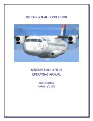
Unlike other aircraft,<br />
Airbus has done away<br />
with the throttle levers<br />
that give the pilot direct<br />
control of engine thrust.<br />
Instead, the Airbus 320<br />
is equipped with thrust<br />
levers that feature<br />
several position detents<br />
and modes of operation.<br />
While on the ground, the<br />
pilot can move the<br />
thrust levers to indicate<br />
the desired thrust<br />
setting. The computer will then command the engines accordingly. When taking<br />
off, the thrust levers are moved to either the TOGA (Take Off/Go Around) detent<br />
or the “Flex” detent if a de-rated takeoff is being performed. In this detent,<br />
the<br />
computer will automatically apply the proper amount of thrust needed for<br />
takeoff. The easiest way to do this in Fight Sim is to press the F4 key on your<br />
keyboard.<br />
Once the aircraft is stable and climbing, the computer will instruct the pilot to<br />
move the levers to the Climb detent. Pressing the F2 key will do this for you. The<br />
throttle levers will remain in this detent until the landing phase.<br />
PAGE 15
Airbus 320 <strong>Operating</strong> <strong>Manual</strong><br />
The next area that should be addressed is the flap setting convention used by<br />
Airbus. Instead of listing the flap settings in degrees as on other aircraft, Airbus<br />
has simply numbered the flap settings as 1, 2, 3, & Full.<br />
<strong>A320</strong> FLIGHT DECK FAMILIARIZATION<br />
Using the DVA <strong>A320</strong> fleet installer aircraft, you will be working in a two<br />
dimensional environment. Above is the instrument panel of the DVA Airbus 320.<br />
Immediately you will notice that most of your gauges are found on the electronic<br />
displays, with only a few standby gauges in case of system failure.<br />
Let’s work from left to right as we review what we’re looking at:<br />
ELECTRONIC FLIGHT INFORMATION SYSTEM (EFIS):<br />
Primary Flight Display (PFD)-This is the<br />
outboard display unit (DU). Within the PFD<br />
display unit we have the electronic speed<br />
tape on the left and altitude ribbon on the<br />
right. Sandwiched between the two is the<br />
Electronic Attitude Direction Indicator<br />
(EADI). On the bottom is an electronic<br />
compass tape for quick reference to heading<br />
PAGE 16
Airbus 320 <strong>Operating</strong> <strong>Manual</strong><br />
with our altimeter setting in the lower right corner. On the very top is the Flight<br />
Mode Annunciator (FMA) that shows us which autopilot functions is engaged.<br />
Navigation Display (ND)<br />
The navigation DU is the inboard DU, appropriately situated next to the PFD. The<br />
ND can display a number of things, such as TCAS target reference, vertical and<br />
horizontal deviation for ILS signals, deviation bars for radio navigation, etc. The<br />
view in the screen shot above is the typical configuration for the DVA <strong>A320</strong>. In<br />
ARC mode you will see the frequencies your navigation radios are tuned to and<br />
where the aircraft is positioned in reference to these radio facilities. See below<br />
for different ND modes.<br />
These are only a few of the different ND modes available, but give you a descent<br />
picture of what’s available. To the left is ARC, center is PLAN, and right is ARC<br />
with WPT selected to display waypoints in your selected range of view.<br />
EFIS Control Panel: This is where you will make selections for the various ND<br />
display views using the selector knobs for system and range as well as the<br />
various push buttons:<br />
CSTR: Shows flight plan constraints on the ND when in ARC mode<br />
WPT: Shows waypoints visible within your selected range<br />
VORD: Shows VOR stations within range<br />
NDB: Shows NDBs within range<br />
ARPT: Shows airports within range<br />
PAGE 17
Airbus 320 <strong>Operating</strong> <strong>Manual</strong><br />
NOTE: Be advised that using the WPT and ARPT buttons with a large range<br />
selected will quickly clutter your display and make it difficult to prioritize. These<br />
are best used with range set to 10NM (20 max).<br />
ELECTRONIC CENRALIZED AIRCRAFT MONITORING (ECAM)<br />
SYSTEM:<br />
Upper ECAM Display (Engine Display)<br />
The center DU on the main instrument panel is part of the ECAM system that<br />
consists of an upper display for engine parameters, and a lower display (partially<br />
visible on the 2D panel) for system synoptic diagrams and indications. Our focus<br />
here is the upper display. This DU presents engine data in the top left quarter of<br />
the display indicating from top to bottom: N1 dial, EGT dial, N2, and Fuel Flow<br />
(FF). The top right quarter of the display shows flap position indications by<br />
diagram and digital readout. The lower left quarter shows takeoff and landing<br />
checklists and presents you with other information during flight, such as<br />
reminders for landing lights and No Smoking and Seatbelt signs. The lower<br />
right<br />
quarter shows auto brake settings.<br />
PAGE 18
STANDBY GAUGES<br />
Airbus 320 <strong>Operating</strong> <strong>Manual</strong><br />
There are a few standby gauges that are essential to flight in the event of a<br />
malfunction that renders the Display Units unusable. From top to bottom they<br />
are:<br />
1. Air Speed (top left)<br />
2. Altimeter with barometric calibration (top right)<br />
3. Attitude Direction Indicator (ADI)<br />
4. Clock (bottom left)<br />
5. Horizontal Situation Indicator (HSI) (bottom right)<br />
PAGE 19
GLARE SHIELD PANEL<br />
Airbus 320 <strong>Operating</strong> <strong>Manual</strong><br />
Moving up we come to the glare shield. Again working from left to right we’ll<br />
review the various controls. (Some of them were briefly covered in the preceding<br />
sections.)<br />
MASTER CAUTION AND WARNING<br />
On the left side of the FCU there are two dark buttons, one on top of the other.<br />
These are the Master Warning and Master Caution buttons. Warning is on top<br />
and flashes red, Caution is below and flashes amber. By pressing them, the lights<br />
are extinguished and the audible tone silenced.<br />
CHRONOMETER AND PRIORITY<br />
Next to the caution and warning buttons is a round push button (pb) labeled<br />
CHRONO. Pressing this button starts the chronometer and displays in the<br />
Navigation Display. This is particularly useful when placed in a holding pattern or<br />
on some other time constraint by ATC. For whatever reason you may need it, it’s<br />
available.<br />
To reset the counter, simply press the button again.<br />
Below the chronometer round push button (pb) is the Side Stick Priority Button.<br />
This is not simulated in this particular panel, but it provides the flight computers<br />
with prioritization between the two side sticks. Assuming you and your first<br />
officer are putting opposing force on the side sticks, the one with priority (CAPT<br />
or Copilot) is the direction the flight computer will command the flight controls.<br />
PAGE 20
EFIS CONTROL PANEL<br />
Airbus 320 <strong>Operating</strong> <strong>Manual</strong><br />
Situated between the autopilot and master caution/warning control panels, the<br />
EFIS control panel is the central interface for manipulating the different views on<br />
the Navigation Display (covered earlier) and managing the barometric altimeter.<br />
The altimeter can be calibrated using inches mercury (inHg), and hectopascals<br />
(hPa). Hectopascal units are the same as QNH readings. Altimeter settings in<br />
certain countries outside the continental United States are reported in hPa,<br />
especially France. You can turn the control knob left or right to change the<br />
setting. Above transition altitude when you return the altimeter to standard,<br />
29.92 inches (1013 hPa), pull the knob. For our <strong>A320</strong>, this is accomplished with a<br />
left mouse click. The digital readout will display STD. To return to the changeable<br />
setting, simply click the push/pull button again and the window will display the<br />
last selected setting.<br />
Below the altimeter controls are two buttons labeled FD and ILS.<br />
FD: Engages/disengages the Flight Director<br />
ILS: Engages/disengages the ILS vertical and lateral deviation dots on the PFD<br />
FLIGHT CONTROL UNIT (FCU)<br />
If you’re a seasoned Boeing pilot, you referred to this as the Mode Control Panel,<br />
or MCP. In the Airbus world, however, we call it the Flight Control Unit, or FCU.<br />
However you want to call it, the functions are similar to what you worked with in<br />
the Boeing airplanes. The control approach is a bit different. Airbus adopted a<br />
PAGE 21
Airbus 320 <strong>Operating</strong> <strong>Manual</strong><br />
push/pull methodology for managing just about all of the controls in the flight<br />
deck. The knobs you see on the FCU are all turn/push/pull. In <strong>Delta</strong> <strong>Virtual</strong><br />
<strong>Airlines</strong>’ <strong>A320</strong>, we simulate a push/pull simply by left clicking the knob.<br />
There are two modes of automatic flight in the Airbus series: Selected and<br />
Managed.<br />
Selected: The pilot is telling the autopilot what you want it to do. For example,<br />
with the auto thrust system engaged, you may dial, or select, a particular speed<br />
you wish the aircraft to fly. The same holds true for heading, and to an extent,<br />
the altitude.<br />
Managed: In this mode, the autopilot is receiving its commands directly from the<br />
Flight Management Guidance Computer (FMGC) based on the data active in the<br />
MCDU.<br />
To better understand the push/pull action, you push the knob to give control to<br />
the FMGC, which commands the autopilot. You pull the knob to take control from<br />
the FMGC. When you are in managed mode, a white dot will appear next to the<br />
numerical readout of the speed, heading, and altitude. You can fly the <strong>A320</strong> in<br />
any mix of modes as well. For example, with the autopilot engaged, you can fly<br />
with speed in select mode with heading and altitude in manage, or any other<br />
combination thereof.<br />
The black button just below the speed window labeled SPD/MACH will change<br />
the speed-reading between knots indicated and Mach.<br />
The black button labeled HDG/TRK VS/FPA located between the two autopilot<br />
buttons does several things, but only one is modeled here for our purposes:<br />
Changes the heading readout to display course setting for radio navigation.<br />
{Real world}: This button also changes our display from vertical speed to flight<br />
path angle. On the PFD you would notice a little circle denoting the actual flight<br />
path angle of the aircraft. This is not simulated in our <strong>A320</strong>.<br />
Altitude may be set in hundreds or thousands of feet. In the actual aircraft we<br />
would be able to use the black button below the altitude window to change<br />
between metric altitude when necessary but this is inoperative in our airplane.<br />
Clicking above the altitude selector knob will allow you to cycle between 100 and<br />
1,000 feet. Click left or right of the knob to increase or decrease your new<br />
altitude.<br />
PAGE 22
In the center of the panel are three buttons:<br />
Airbus 320 <strong>Operating</strong> <strong>Manual</strong><br />
AP1 / AP2: Engages or disengages #1 or #2 autopilot.<br />
A/THR: Engages or disengages auto thrust<br />
These buttons illuminate when they are activated. The lights extinguish when the<br />
system is disengaged.<br />
This is the end of our familiarization briefing. Please be sure to review the<br />
complete panel documentation as the overhead and pedestal panels are also<br />
available, but are beyond the scope of this tutorial. Having familiarized ourselves<br />
with the flight deck layout and some of the more important panels and functions,<br />
we’re now ready to begin our first flight!<br />
PAGE 23
Flying the aircraft – Tutorial<br />
Airbus 320 <strong>Operating</strong> <strong>Manual</strong><br />
The purpose of this tutorial is to familiarize the pilot with the operation of the<br />
<strong>Delta</strong> <strong>Virtual</strong> <strong>Airlines</strong> fleet <strong>A320</strong>. The starting point will be in a ‘cold and dark’<br />
cockpit parked at the gate. We will also assume fuel planning and loading is<br />
complete – see the Fuel Planning section of this manual for detailed fuel planning<br />
and loading guidance. Because the <strong>A320</strong> is a Stage 2 aircraft, we will assume the<br />
pilot possesses some knowledge of basic procedures including communicating<br />
with ATC and determining taxi routes or runways to use.<br />
Let’s get started. Load your flight simulator with the fleet <strong>A320</strong>. Make sure<br />
appropriate payload and fuel loading is complete using the Flight Simulator fuel<br />
and payload menus. At this point you should be in the aircraft at the Captain’s<br />
“Main” panel. Before applying power to the aircraft certain safety checks must be<br />
completed.<br />
Main Panel<br />
1. Flight Director (F/D) ......................... ON<br />
2. A/T and AP ...................................... OFF<br />
Landing Gear Panel<br />
1. Gear Handle .................................... DOWN<br />
Throttle Quadrant<br />
1. Parking Brake .................................. SET<br />
2. Engine Switches 1 & 2 ..................... OFF (Down)<br />
3. Engine Ignition Selector ................... NORM<br />
4. Speed Brakes ................................. RET<br />
4. Flaps ............................................... 0 (Up)<br />
5. Throttles ......................................... IDLE DETENT<br />
Overhead<br />
1. Nav & Logo lights ............................. ON<br />
PAGE 24
Now it’s time to apply power and continue preflight checks.<br />
Overhead<br />
1. Battery ........................................... ON (no light)<br />
2. APU Start Button .............................. ON<br />
3. APU Generator Access Bus ................ ON (no light)<br />
4. ADIRS system .................................. ON<br />
5. FLT CTL buttons .............................. ON (no light)<br />
6. Generators 1 & 2 ............................. ON (no light)<br />
7. Fire agent buttons (1, 2, & APU) ....... No lights<br />
8. Air Cross Bleed Selector .................... AUTO<br />
9. Cabin Signs ..................................... On & On<br />
10. Electric Hyd pump .......................... AUTO (no light)<br />
11. Fuel cross feed ............................... OFF (no light)<br />
12. Wing and engine anti-ice ................ OFF (no light)<br />
13. Probe Heat .................................... AUTO (no light)<br />
Airbus 320 <strong>Operating</strong> <strong>Manual</strong><br />
If you are flying online, obtain your necessary ATC Clearance.<br />
Now that we have our clearance and should know the departure runway, it is<br />
time to program the desired route into the aircraft’s navigation system. The fleet<br />
<strong>A320</strong> uses Flight Simulator’s default GPS as its main navigation system. This may<br />
be programmed using the Flight Planner within Flight Simulator when using<br />
multiple waypoints or via the GPS panel view for a more direct route. At this level<br />
of your virtual career, you should be familiar with the basics of proper departure<br />
and approach procedures, functionality that is available by using Flight<br />
Simulator’s Flight Planner.<br />
After the GPS is configured, we should complete the flight deck preparations<br />
based on the clearance information provided by ATC.<br />
Main Panel<br />
1. NAV/GPS selector ............................. NAV<br />
2. Barometric Pressure ......................... SET<br />
3. Speed ............................................. SET<br />
4. HDG ............................................... Set<br />
PAGE 25
5. Initial Altitude .................................. SET<br />
6. V/S ................................................. SET<br />
Airbus 320 <strong>Operating</strong> <strong>Manual</strong><br />
It’s finally time to push back. Ensure the APU is running by pressing the APU<br />
selector button.<br />
The aircraft is now ready for pushback and engine start. If flying online with<br />
ATC, obtain push pack and engine start clearance first. Immediately prior to start<br />
and push, activate the beacon via the overhead panel, release the parking brake,<br />
and push back using the method you prefer.<br />
When the push back is complete, set the parking brake. Once stopped and the<br />
brake is set, it is time to start engines. The <strong>A320</strong> relies heavily on its automated<br />
systems and engine start is no different. First select the ENG selector on the<br />
main panel to call up the engine display. Then, on the throttle quadrant, move<br />
the engine #2 selector to the up or ON position. Monitor the engine data via the<br />
selected display.<br />
Once engine #2 has stabilized, it’s time to repeat the start sequence for engine<br />
#1. Again, monitor the engine data during start-up.<br />
Now that the engines are started, we can shut off the APU. Select the APU<br />
button to bring up the APU display. On the overhead panel, select OFF on the<br />
APU GEN button and press the APU Start button to shut-off the APU. Monitor the<br />
APU status on the APU display.<br />
Set the flaps for takeoff via the throttle pedestal panel (normally Flaps 1) and<br />
activate the anti-skid and nose wheel steering on the landing gear panel.<br />
If flying with ATC, obtain your taxi clearance. Once approved, turn on the taxi<br />
light via the overhead panel and advance the throttles slowly to begin forward<br />
motion. As you taxi to the departure runway, remember straight ahead taxi<br />
speeds should not exceed 30 knots ground speed and turning speeds should not<br />
exceed 12 knots ground speed.<br />
Once at the runway obtain your takeoff clearance if flying with ATC guidance.<br />
PAGE 26
Once cleared for takeoff, complete these remaining tasks.<br />
Overhead<br />
1. Strobe ............................................ ON<br />
2. Landing Lights ................................. ON<br />
Airbus 320 <strong>Operating</strong> <strong>Manual</strong><br />
Now taxi onto the runway and line up on the centerline. Once aligned, activate<br />
the auto throttle and click the TO/GA button on the throttle pedestal. Maintain<br />
runway alignment and monitor engine performance during takeoff roll. Monitor<br />
your speed and at Vr apply backpressure and smoothly rotate to an approximate<br />
10-degree nose up attitude. Rotation rate should be about 3 degrees per second.<br />
Maintain this attitude until liftoff and a positive rate of climb is achieved. Watch<br />
your airspeed and ensure you stay below 250 knots. Once a positive rate of<br />
climb is established and the altitude has increased beyond 35’ AGL, retract the<br />
gear. You may also turn off the taxi light.<br />
Once safely airborne, click the A/P button and engage the heading, speed, and<br />
altitude modes by pressing the specific knobs. Ensure that the airspeed<br />
continues to increase towards your selected airspeed and do not exceed the 250<br />
knots speed restriction. Retract the flaps to 0 when passing 220 knots.<br />
As your speed stabilizes at the target speed, you can increase the rate of climb.<br />
Don’t be too aggressive or your speed will decay. Continue your climb out<br />
complying with any departure restrictions. Passing 10,000 feet set the target<br />
speed to 290 knots, unless your departure procedure dictates otherwise, and<br />
turn off the landing lights.<br />
Once you are given clearance to proceed as filed, press the GPS button on the<br />
main panel and select LOC. The aircraft will begin to turn towards your first<br />
programmed waypoint. Although the GPS is now guiding the aircraft, be sure to<br />
monitor each waypoint segment to ensure proper navigation.<br />
Once passing 18,000 feet, select 29.92 for your barometric pressure and select<br />
your cruise speed. If you will be cruising above FL230, make sure to toggle the<br />
SPD/MACH selector button to change the speed values to MACH. As you climb<br />
towards your cruising altitude, you may reduce your vertical speed incrementally<br />
to ensure a smooth transition to level flight and maintain your airspeed.<br />
PAGE 27
Airbus 320 <strong>Operating</strong> <strong>Manual</strong><br />
When approximately 200 miles from your destination obtain the current weather<br />
and determine the landing runway. Yes, you selected a landing runway during<br />
preflight but weather does change especially during longer flights.<br />
Once cleared, you may begin your descent. Manage your descent by selecting<br />
the desired altitude and vertical speed. Make sure you will be below 250 knots<br />
prior to descending through 10,000 feet. It is also company policy to turn on the<br />
landing lights when below 10,000 feet.<br />
We will assume you are flying an ILS approach. Tune in the ILS Frequency in<br />
preparation for landing. Select the NAV button on the main panel to activate the<br />
navigation radios. Toggle the ILS button to display the localizer and glideslope<br />
indicator on the PFD. Continue your arrival towards the Initial Approach Fix<br />
(IAF). Plan to reach that point at the charted altitude and 190 KIAS. A good rule<br />
of thumb is to deploy FLAPS 1 when slowing thru 200 KIAS. Depart the Initial<br />
Approach Fix by following the approach plate information. When you are<br />
receiving the localizer and glide slope, you can select APR button on the main<br />
panel. Continue flap deployment to Flaps 3 in stabilized segments.<br />
Maintain 180 KIAS until glide slope intercept occurs or you reach a point 10 NM<br />
from the runway. At this point, reduce your target speed to 160 KIAS deploying<br />
flaps to FULL. Lower the landing gear and turn on the taxi light.<br />
Maintain a stable approach and disengage the autopilot and auto throttle as<br />
conditions dictate. When approximately 50 feet off the runway, pull the throttles<br />
all the way back to idle. When about 30 feet off the runway, increase pitch about<br />
3 degrees to flare the aircraft. Hold this attitude until touchdown. On touchdown,<br />
deploy the spoilers (/) and manually apply reverse thrust by pressing and holding<br />
the F2 key. Maintain runway alignment and slow the aircraft. When slowing<br />
through 80 KIAS, stow the reverse thrust be pressing the F1 key. Slow to taxi<br />
speed and turn off the runway.<br />
Once off the runway<br />
Overhead<br />
1. Strobes .......................................... OFF<br />
2. Landing Lights ................................ OFF<br />
3. APU ............................................... START<br />
PAGE 28
Throttle Pedestal<br />
1. Spoilers ........................................... RETRACTED<br />
2. Flaps .............................................. 0<br />
Airbus 320 <strong>Operating</strong> <strong>Manual</strong><br />
If ATC is present, obtain you taxi clearance and taxi to the gate using the same<br />
procedures you did on the way out. Once at the gate:<br />
Throttle Pedestal<br />
1. Parking Brakes ................................. SET<br />
2. Engine switches ............................... OFF<br />
Overhead<br />
1. Taxi light ......................................... OFF<br />
2. Beacon ............................................ OFF<br />
3. Seat belt signs ................................ OFF<br />
Congratulations! You have just completed your first of many flights in the <strong>A320</strong>.<br />
PAGE 29
Fuel Planning and Weight and Balance<br />
Airbus 320 <strong>Operating</strong> <strong>Manual</strong><br />
Detailed Fuel Planning is covered in the Flight Encyclopedia. All burn rates are<br />
per engine and were measured at the maximum aircraft gross weight for the<br />
altitude and therefore should reflect the worst-case scenario.<br />
Altitude Indicated<br />
Airspeed<br />
True Airspeed Fuel Burn<br />
Ground Operations N/A N/A 400 PPH<br />
12,000’ 290 KIAS 360 KTAS 1395 PPH<br />
FL180 290 KIAS 394 KTAS 1391 PPH<br />
FL240 290 KIAS 429 KTAS 1410 PPH<br />
FL300 300 KIAS 480 KTAS 1501 PPH<br />
FL360 260 KIAS 447 KTAS 1100 PPH<br />
Fuel Loading<br />
<strong>Delta</strong> <strong>Virtual</strong>’s Airbus <strong>A320</strong> variants have three (A319, A321) or five (A318, <strong>A320</strong>)<br />
fuel tanks as outlined in the table below.<br />
Model/Tank Center Left Main Right Main Left Aux Right Aux<br />
A318 14,605 lbs 12,256 lbs 12,256 lbs 1,554 lbs 1,554 lbs<br />
A319 14,605 lbs 13,814 lbs 13,813 lbs - -<br />
<strong>A320</strong> 14,605 lbs 12,256 lbs 12,256 lbs 1,554 lbs 1,554 lbs<br />
A321 19,642 lbs 13,713 lbs 13,713 lbs - -<br />
To load fuel into your aircraft, select Aircraft, then Fuel and place the correct<br />
fuel amounts in the correct tanks.<br />
PAGE 30
Checklists<br />
FLIGHT DECK PREPARATION<br />
Airbus 320 <strong>Operating</strong> <strong>Manual</strong><br />
o All Charts/Flight Plan ....... On Board<br />
o Parking Brake .................. ON<br />
o Throttle Levers ................ IDLE<br />
o Engine Ignition Switches ... OFF<br />
o Battery ............................ ON<br />
o Landing Gear ................... DOWN<br />
o Flaps/Slats ....................... 0 (Up) (ECAM AGREE)<br />
o Spoilers ........................... RETRACTED<br />
o Flight Plan ....................... Loaded (FS Flight Planner or GPS)<br />
o Fuel Qty .......................... CHECK<br />
o Cabin Signs ..................... ON<br />
o Nav Lights ....................... ON<br />
AT GATE PARKED-BEFORE ENGINE START<br />
o All Charts/Flight Plan ....... On Board<br />
o Weight/Balance ............... Meet Flight Requirements (Check<br />
charts)<br />
o ACARS (optional) ............. Connected and Flight Started<br />
o ATC Flight Clearance (if online) RECEIVED<br />
o Altimeter ........................ SET<br />
o Transponder .................... SET/Standby<br />
o COM1 ............................. SET as needed<br />
o NAV 1 & 2 ...................... SET as needed<br />
o ADF ................................ SET as needed<br />
o Airspeed Bug (A/P) ........... SET<br />
o Heading Bug (A/P) ........... SET<br />
o Altitude (A/P) ...........................SET<br />
ATC CLEARANCE - Call for IFR/VFR Departure-Push/Start Request (if flying<br />
online)<br />
o All doors ......................... Closed / Locked<br />
o Rotating Beacon Switch .... ON<br />
o Parking Brakes ................. RELEASED<br />
o Clock/Chrono ................... START<br />
o Pushback ......................... START<br />
-BEFORE ENGINE START CHECKLIST COMPLETED-<br />
PAGE 31
ENGINE START<br />
o BATT Master Switch ......... ON<br />
o Throttle ........................... IDLE<br />
o Parking Brakes ................ SET<br />
o APU ................................ ON<br />
o #2 Engine Switch (right) ... ON<br />
o Engine instruments .......... N1 Increase, Stable<br />
o Generator Switch ............. ON<br />
o #1 Engine Switch (left) ..... ON<br />
o Engine instruments .......... N1 Increase, Stable<br />
o Generator Switch ............. ON<br />
o APU ................................ OFF<br />
AFTER ENGINE START<br />
TAXI<br />
-ENGINE START CHECKLIST COMPLETED-<br />
o Internal Lights ................. AS NEEDED<br />
o Taxi Light ........................ ON<br />
o Pitot Heat ........................ ON<br />
o Elevator Trim ................... SET (+1.0)<br />
o Autopilot ......................... SET<br />
o Flaps ............................... 1<br />
-AFTER ENGINE START CHECKLIST COMPLETED-<br />
Airbus 320 <strong>Operating</strong> <strong>Manual</strong><br />
ATC TAXI CLEARANCE - Request taxi to active runway (if online)<br />
o Parking Brakes ................. RELEASED<br />
o GPS/NAV Switch ............... NAV<br />
o Flight Controls ................. CHECKED (Free & Clear)<br />
o Crew takeoff briefing ........ COMPLETE<br />
o Crew announcements ....... COMPLETE<br />
-TAXI CHECKLIST COMPLETED-<br />
PAGE 32
BEFORE TAKEOFF<br />
o Flight Director .................. ON<br />
o Auto Pilot ........................ SET (Checked)<br />
o Flaps ............................... 1 (Checked)<br />
o Spoilers ........................... RETRACTED (Checked)<br />
ATC Take off CLEARANCE - Request for takeoff<br />
-BEFORE TAKEOFF CHECKLIST COMPLETED-<br />
TAKEOFF - CLEARED OR TAXI INTO POSITION & HOLD<br />
CRUISE<br />
o Parking Brakes ................. RELEASED<br />
o Strobe & Landing Lights .... ON<br />
o Transponder .................... ON / Normal<br />
-TAKEOFF CHECKLIST COMPLETED-<br />
After Takeoff / Climb<br />
o Gear ............................... UP (Lights Out)<br />
o Flaps ............................... 0 (UP)<br />
o Spoilers ........................... RETRACTED<br />
o Taxi Light ........................ OFF<br />
Passing 10,000 Ft MSL<br />
o Landing Lights ................. OFF<br />
o Seat Belt Signs ................. OFF (as conditions permit)<br />
Passing 18,000 Ft MSL<br />
o Altimeters ........................ STD (29.92)<br />
o Engine Instruments .......... MONITOR<br />
o Fuel Consumption ............ MONITOR<br />
o Navigation ..............................MONITOR<br />
-CRUISE CHECKLIST COMPLETED-<br />
PAGE 33<br />
Airbus 320 <strong>Operating</strong> <strong>Manual</strong>
DESCENT<br />
APPROACH<br />
LANDING<br />
ATC Descent CLEARANCE – Descend<br />
Passing 18,000 Ft MSL<br />
o Altimeters ........................ SET<br />
o Seat Belt Signs ................. ON<br />
Passing 10,000 Ft MSL<br />
o Landing Lights ................. ON<br />
-DESCENT CHECKLIST COMPLETED-<br />
ATC Approach CLEARANCE - Approach<br />
o GPS/NAV Switch ............... NAV<br />
o ILS Freq .......................... SET<br />
o Flaps ............................... AS SCHEDULED<br />
-APPROACH CHECKLIST COMPLETED-<br />
ATC Landing CLEARANCE - to Land<br />
o Landing Gear ................... DOWN (Three Green)<br />
o Taxi Light ........................ ON<br />
o Flaps ............................... FULL<br />
o Autopilot ......................... OFF<br />
o Auto throttle .................... OFF<br />
-LANDING CHECKLIST COMPLETED-<br />
PAGE 34<br />
Airbus 320 <strong>Operating</strong> <strong>Manual</strong>
AFTER LANDING (WHEN CLEAR OF THE RUNWAY)<br />
ATC Taxi CLEARANCE - To gate<br />
o Landing Lights ................. OFF<br />
o Strobe Lights ................... OFF<br />
o Transponder .................... Standby<br />
o Flaps ............................... 0 (UP)<br />
o Spoilers ........................... RETRACTED<br />
o APU........................................ON<br />
AT THE GATE / SHUTDOWN<br />
-AFTER LANDING CHECKLIST COMPLETED-<br />
o Parking Brakes .........................SET<br />
o Clock/Chrono ...........................OFF<br />
o Taxi Light ................................OFF<br />
o Engine Switches .......................OFF<br />
o Rotating Beacon Light ...............OFF<br />
o Seat Belt Sign ..........................OFF<br />
o ACARS Shutdown (optional)<br />
o ........................................................ End Flight, File PIREP<br />
Airbus 320 <strong>Operating</strong> <strong>Manual</strong><br />
NOT FOR REAL WORLD AVIATION USE<br />
PAGE 35
Crew Briefings<br />
TAKEOFF<br />
Captain to Co-pilot<br />
LANDING<br />
Airbus 320 <strong>Operating</strong> <strong>Manual</strong><br />
We will be taking off on RWY (active runway), climbing to (altitude). If<br />
we encounter an engine malfunction, fire or other emergency before V1<br />
(critical engine failure recognition speed) KIAS, the flying pilot will retard<br />
the throttles to flight idle and bring the aircraft to a complete stop on the<br />
runway. The non flying pilot will notify the proper ATC of our intentions<br />
and assist the flying pilot as requested or needed to operate the aircraft in<br />
a safe manner.<br />
If the aircraft has reached Vr (rotate speed) KIAS, the flying pilot will fly<br />
the aircraft per company procedures and the non flying pilot will notify the<br />
appropriate ATC of our intentions and assist the flying pilot as requested<br />
or needed to operate the aircraft in a safe manner and land the aircraft as<br />
soon as possible.<br />
Captain to Co-pilot<br />
Aircraft Weight is: ______ Taxi Instructions to Active: _________<br />
V Speeds for this flight are (calculated) See prepared Flip Chart(s)<br />
Flap Settings: Takeoff _____ Engine Failure Approach ______<br />
Discuss the Departure Procedures for this flight (Ref Charts, SIDs)<br />
Discuss Weather considerations (Ref ATIS, METAR, TF)<br />
Weather conditions are (obtain from ATIS, Metar and TF).<br />
Landing on RWY (active runway) at (airport) using the (???) approach<br />
(Ref STAR)<br />
Descend at (???). Our Final Approach altitude will be (???)<br />
V Speeds for this approach are (calculated) (See prepared Flip Chart(s))<br />
PAGE 36
Missed approach Procedures are (Ref Approach Plates)<br />
Taxiway Turnoff _____<br />
Taxi Route from Active ________________<br />
Parking at Gate (#)<br />
CREW ANNOUNCEMENTS<br />
Departure<br />
Airbus 320 <strong>Operating</strong> <strong>Manual</strong><br />
“Ladies and gentlemen, on behalf of the flight crew, this is your (captain<br />
or first officer) (insert name), welcoming you aboard <strong>Delta</strong> <strong>Virtual</strong> <strong>Airlines</strong><br />
flight number (flight) with service to (destination). Our flight time today<br />
will be approximately (time en route) to (destination). At this time, I’d like<br />
to direct your attention to the monitors in the aisles for an important<br />
safety announcement. Once again, thank you for flying <strong>Delta</strong> <strong>Virtual</strong><br />
<strong>Airlines</strong>.”<br />
Climbing above 10,000 feet MSL<br />
Inform cabin crew that use of approved electronic devices is authorized.<br />
At Cruise Altitude<br />
Approach<br />
Landing<br />
“Ladies and gentlemen,<br />
this is the (Captain or First Officer) speaking.<br />
We’ve reached our cruising altitude of (altitude). We should be<br />
approximately (time) enroute and expect to have you at the gate<br />
on time.<br />
I’ve turned off the fasten seatbelt sign, however, we ask that while in<br />
your seat you keep your seatbelt loosely fastened as turbulence is often<br />
unpredicted. Please let us know if there is anything we can do to make<br />
your flight more comfortable, so sit back and enjoy your flight.”<br />
Inform<br />
cabin crew of approach and to discontinue use of electronic<br />
devices.<br />
“On<br />
behalf of <strong>Delta</strong> <strong>Virtual</strong> <strong>Airlines</strong> and your entire flight crew we’d like to<br />
welcome you to (destination) where the local time is (time). We hope<br />
you’ve enjoyed your flight with us today and hope that the next time your<br />
plans call for air travel, you’ll choose us again. Once again, thank you for<br />
flying <strong>Delta</strong> <strong>Virtual</strong> <strong>Airlines</strong>.”<br />
PAGE 37
Appendix – <strong>Operating</strong> Information<br />
TAXI SPEEDS:<br />
Airbus 320 <strong>Operating</strong> <strong>Manual</strong><br />
Do not exceed 20 knots on straight taxiways. Do not exceed 10 knots in turns<br />
and when approaching gates or other parking areas.<br />
Exit high-speed taxiways at no more than 35 knots, low speed taxiways at no<br />
more than 15 knots.<br />
TYPICAL V SPEEDS<br />
CLIMB PROFILE<br />
STANDARD CLIMB RATES<br />
DESCENT RATE<br />
V Speed KIAS<br />
V1 149 KIAS<br />
VR 149 KIAS<br />
V2 152 KIAS<br />
Speed Altitude<br />
V2 + 20 KIAS 1,500 ft AFE<br />
250 KIAS 10,000 ft<br />
290 KIAS FL180<br />
.74 mach FL240<br />
.78 mach FL280<br />
.78 mach Cruise Alt<br />
FPM Altitude<br />
2000 - 2200 Below 10,000 ft<br />
1000 - 2000 10,000 ft to FL180<br />
1000 - 2000 FL180 to FL280<br />
500 – 1500 Above FL280<br />
Target Speed Descent Rate Altitude<br />
290 KIAS 2200 fpm Cruise to 10,000 ft MSL<br />
250 KIAS 1500 fpm Below 10,000 ft MSL<br />
PAGE 38
APPROACH/LANDING SPEED PROFILE<br />
FLAP SPEEDS<br />
Airbus 320 <strong>Operating</strong> <strong>Manual</strong><br />
Speed Altitude<br />
Distance from<br />
Airport<br />
Flaps<br />
240 KIAS Below 10,000 feet 30 nm Up<br />
200 KIAS 15 nm 1<br />
190 KIAS 10 nm 2<br />
160 KIAS Varies Final Approach Fix 3 or Full<br />
Vref + 5 Varies 3 or Full<br />
Vref + 5 Varies Runway Threshold 3 or Full<br />
Flap Position Flap Degrees Maximum Speed<br />
0 Slats 0°<br />
Flaps 0°<br />
N/A<br />
1 Slats 18°<br />
Flaps 10°<br />
230 KIAS<br />
2 Slats 22°<br />
Flaps 15°<br />
200 KIAS<br />
3 Slats 22°<br />
Flaps 20°<br />
185 KIAS<br />
4 (Full) Slats 27°<br />
Flaps 35°<br />
177 KIAS<br />
PAGE 39
Acknowledgements and Legal Stuff<br />
PAGE 40<br />
Airbus 320 <strong>Operating</strong> <strong>Manual</strong><br />
<strong>Delta</strong> <strong>Virtual</strong> <strong>Airlines</strong> 2009 Copyright © 2009 Global <strong>Virtual</strong> <strong>Airlines</strong> Group. All<br />
rights reserved.<br />
For flight simulation purposes only. In no way are we affiliated with <strong>Delta</strong> Air<br />
Lines, its affiliates, or any other airline. All logos, images, and trademarks<br />
remain the property of their respective owners. <strong>Delta</strong> <strong>Virtual</strong> <strong>Airlines</strong> is a nonprofit<br />
entity engaged in providing an avenue for flight simulation enthusiasts.<br />
Larry Foltran and Ryan Watkins created this manual in 2009.<br />
Flight Sim screenshots courtesy Larry Foltran.<br />
This manual is copyright 2009. The authors grant unlimited rights to <strong>Delta</strong><br />
<strong>Virtual</strong> <strong>Airlines</strong> for modification and non-profit electronic duplication and<br />
distribution. Materials from outside sources were used and other copyrights may<br />
apply. All cited sections remain the property of their authors.<br />
While we strive to mirror real-world operations, this manual is not designed for<br />
use in the operation of real-world aircraft.<br />
NOT FOR REAL WORLD AVIATION USE