Tool Support for Seamless System Development based on ...
Tool Support for Seamless System Development based on ...
Tool Support for Seamless System Development based on ...

You also want an ePaper? Increase the reach of your titles
YUMPU automatically turns print PDFs into web optimized ePapers that Google loves.
Abstract<br />
<str<strong>on</strong>g>Tool</str<strong>on</strong>g> <str<strong>on</strong>g>Support</str<strong>on</strong>g> <str<strong>on</strong>g>for</str<strong>on</strong>g> <str<strong>on</strong>g>Seamless</str<strong>on</strong>g> <str<strong>on</strong>g>System</str<strong>on</strong>g> <str<strong>on</strong>g>Development</str<strong>on</strong>g> <str<strong>on</strong>g>based</str<strong>on</strong>g> <strong>on</strong><br />
AUTOSAR Timing Extensi<strong>on</strong>s<br />
Oliver Scheickl, Christoph Ainhauser<br />
BMW Car IT GmbH<br />
Many software-<str<strong>on</strong>g>based</str<strong>on</strong>g> functi<strong>on</strong>s in modern cars have<br />
strict timing c<strong>on</strong>straints. Due to the ever growing number<br />
of such functi<strong>on</strong>s and the trend towards higher integrati<strong>on</strong>,<br />
the development of automotive systems is<br />
becoming more complex. The industry has realised<br />
that model-<str<strong>on</strong>g>based</str<strong>on</strong>g> software engineering approaches are<br />
required to cope with this increasing complexity and,<br />
am<strong>on</strong>g others, to ensure the fulfilment of the timing<br />
c<strong>on</strong>straints. There<str<strong>on</strong>g>for</str<strong>on</strong>g>e, different kinds of tools are required<br />
<str<strong>on</strong>g>for</str<strong>on</strong>g> the various engineering steps during the whole<br />
timing-aware development process.<br />
For AUTOSAR systems, the tooling <str<strong>on</strong>g>for</str<strong>on</strong>g> timing-aware<br />
development is not yet fully satisfying. First, most of<br />
the existing tools focus <strong>on</strong>ly <strong>on</strong> a specific step of the engineering<br />
process. Sec<strong>on</strong>d, if at all, today’s interacti<strong>on</strong><br />
of tools is often realised as two-sided island soluti<strong>on</strong>s<br />
<str<strong>on</strong>g>based</str<strong>on</strong>g> <strong>on</strong> proprietary import and export interfaces. <str<strong>on</strong>g>Tool</str<strong>on</strong>g><br />
interacti<strong>on</strong> however is required to allow specific tools <str<strong>on</strong>g>for</str<strong>on</strong>g><br />
single engineering steps to be integrated into a seamless<br />
tool support. To our best knowledge, the existing approaches<br />
are neither <str<strong>on</strong>g>based</str<strong>on</strong>g> <strong>on</strong> a comm<strong>on</strong> infrastructure<br />
nor <strong>on</strong> a standardised timing model. Finally, appropriate<br />
tools <str<strong>on</strong>g>for</str<strong>on</strong>g> the specificati<strong>on</strong> of AUTOSAR timing<br />
requirements are missing.<br />
This paper proposes a tool support <str<strong>on</strong>g>for</str<strong>on</strong>g> seamless timing<br />
specificati<strong>on</strong>, analysis and verificati<strong>on</strong> that overcomes<br />
the current challenges. The soluti<strong>on</strong> integrates a) Artime,<br />
a textual editor to specify timing requirements,<br />
b) Gliwa’s timing suite T1, a target timing measurement<br />
tool to gather timing guarantees and c) Artip, a<br />
graphical timing verificati<strong>on</strong> tool, which compares requirements<br />
and guarantees and visualises the results.<br />
Our approach integrates all tools necessary <str<strong>on</strong>g>for</str<strong>on</strong>g> a seamless<br />
model-<str<strong>on</strong>g>based</str<strong>on</strong>g> system development <str<strong>on</strong>g>based</str<strong>on</strong>g> <strong>on</strong> the standardised<br />
timing model offered by the AUTOSAR Timing<br />
Extensi<strong>on</strong>s. We implemented Artime, Artip and the<br />
integrati<strong>on</strong> of Gliwa’s timing tool suite T1 as plug-ins<br />
<str<strong>on</strong>g>for</str<strong>on</strong>g> Artop [6].<br />
We applied this approach in a series development<br />
project at BMW Group. In the project we showed how<br />
our proposed tool support <str<strong>on</strong>g>for</str<strong>on</strong>g> seamless system development<br />
improves the applicati<strong>on</strong> of the AUTOSAR Timing<br />
Extensi<strong>on</strong>s in practice. The tool support, its embedding<br />
in the engineering process, and the results of the applicati<strong>on</strong><br />
are presented in this paper.<br />
Keywords: AUTOSAR, Timing Extensi<strong>on</strong>s, Timing<br />
Model, Timing Analysis, <str<strong>on</strong>g>Tool</str<strong>on</strong>g> <str<strong>on</strong>g>Support</str<strong>on</strong>g>, Practical Use,<br />
Artop, Artime, T1<br />
1<br />
Peter Gliwa<br />
Gliwa GmbH<br />
1 Introducti<strong>on</strong><br />
Modern car functi<strong>on</strong>s, realized by electr<strong>on</strong>ics and software,<br />
have driven many innovati<strong>on</strong>s in the automotive<br />
industry. Meanwhile, complex functi<strong>on</strong>s are present in<br />
many small-sized premium cars as well and define the<br />
new standard of user experience and driver assistance<br />
<str<strong>on</strong>g>for</str<strong>on</strong>g> the near future. The functi<strong>on</strong>s are typically provided<br />
by interactive distributed real-time systems. The development<br />
of these vehicle electrical systems is a complex<br />
task (see <str<strong>on</strong>g>for</str<strong>on</strong>g> example [2, 7]).<br />
Some of the car functi<strong>on</strong>s must be provided within<br />
given time bounds to functi<strong>on</strong> properly. Timing c<strong>on</strong>straints<br />
are typically driven by physics (e.g. repetiti<strong>on</strong><br />
rate of c<strong>on</strong>trol loops) or derived from end user requirements<br />
(e.g. immediate reacti<strong>on</strong> to user input). As many<br />
parts of modern vehicle electrical systems are software<str<strong>on</strong>g>based</str<strong>on</strong>g>,<br />
correct timing behaviour of the software is vital<br />
to the fulfilment of timing c<strong>on</strong>straints.<br />
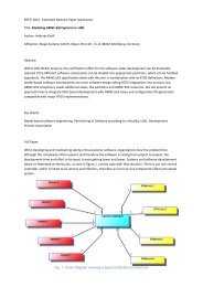
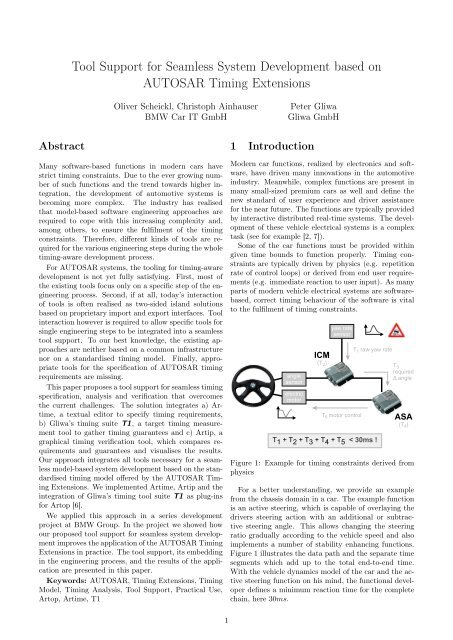
Figure 1: Example <str<strong>on</strong>g>for</str<strong>on</strong>g> timing c<strong>on</strong>straints derived from<br />
physics<br />
For a better understanding, we provide an example<br />
from the chassis domain in a car. The example functi<strong>on</strong><br />
is an active steering, which is capable of overlaying the<br />
drivers steering acti<strong>on</strong> with an additi<strong>on</strong>al or subtractive<br />
steering angle. This allows changing the steering<br />
ratio gradually according to the vehicle speed and also<br />
implements a number of stability enhancing functi<strong>on</strong>s.<br />
Figure 1 illustrates the data path and the separate time<br />
segments which add up to the total end-to-end time.<br />
With the vehicle dynamics model of the car and the active<br />
steering functi<strong>on</strong> <strong>on</strong> his mind, the functi<strong>on</strong>al developer<br />
defines a minimum reacti<strong>on</strong> time <str<strong>on</strong>g>for</str<strong>on</strong>g> the complete<br />
chain, here 30ms.
The example includes sensors (yaw rate, angle), buses<br />
(CAN, Flexray), ECUs 1 (ICM 2 , ASA 3 ) and actuators<br />
(motor driver).<br />
The angle sensor and its CAN c<strong>on</strong>necti<strong>on</strong> to the ICM<br />
is also affected by the timing c<strong>on</strong>straints. For the sake<br />
of simplicity it is not c<strong>on</strong>sidered in this paper.<br />
T1 and T5 in the example are mostly hardware dependent<br />
and typically produce a c<strong>on</strong>stant delay in the<br />
path. T3 reflects the communicati<strong>on</strong> overhead produced<br />
by the Flexray bus – depending <strong>on</strong> the Flexray c<strong>on</strong>figurati<strong>on</strong>.<br />
T2 and T4 represent the time spent “within” an<br />
ECU <str<strong>on</strong>g>for</str<strong>on</strong>g> receiving, processing and transmitting data.<br />
This paper focuses <strong>on</strong> such ECU internal timing. It<br />
is influenced by a number of things: scheduling strategy,<br />
executi<strong>on</strong> times, blocking times, operating system<br />
c<strong>on</strong>figurati<strong>on</strong>, communicati<strong>on</strong> strategies, communicati<strong>on</strong><br />
buffer sizes and synchr<strong>on</strong>isati<strong>on</strong> effects. Flexray<br />
communicati<strong>on</strong> typically introduces synchr<strong>on</strong>isati<strong>on</strong> effects<br />
since the ECU internal schedule with its periodical<br />
tasks <str<strong>on</strong>g>based</str<strong>on</strong>g> <strong>on</strong> its ECU internal clock source has to be<br />
synchr<strong>on</strong>ised with the independent Flexray timing. The<br />
use case described later in Sec. 5 <str<strong>on</strong>g>for</str<strong>on</strong>g> example includes<br />
timing c<strong>on</strong>straints related to the Flexray synchr<strong>on</strong>isati<strong>on</strong>.<br />
It is important to a) be aware of the system’s timing<br />
c<strong>on</strong>straints, b) clearly document and specify the c<strong>on</strong>straints<br />
and c) verify that these c<strong>on</strong>straints are met<br />
in the producti<strong>on</strong> software. Documentati<strong>on</strong> and verificati<strong>on</strong><br />
of timing c<strong>on</strong>straints become especially important<br />
<str<strong>on</strong>g>for</str<strong>on</strong>g> the distributed development process typical of<br />
the automotive industry. For a single ECU, suppliers<br />
and car manufacturers c<strong>on</strong>tribute parts of the software<br />
as black-boxes. More and more, these black-boxes are<br />
AUTOSAR software comp<strong>on</strong>ents with well-defined interfaces.<br />
When integrated together in <strong>on</strong>e ECU, these<br />
comp<strong>on</strong>ents influence the timing <strong>on</strong> a system level with<br />
all its preempti<strong>on</strong>s and c<strong>on</strong>current run-time requirements<br />
[8, 7].<br />
Since AUTOSAR Release 4.0 (Dec. 2009), timing behaviour<br />
can be described as so-called Timing Extensi<strong>on</strong>s<br />
<str<strong>on</strong>g>for</str<strong>on</strong>g> software comp<strong>on</strong>ents, compositi<strong>on</strong>s, basic software<br />
and <str<strong>on</strong>g>for</str<strong>on</strong>g> the entire system [1]. The resulting specificati<strong>on</strong>s<br />
can be exchanged between development teams either<br />
as timing requirements or as timing guarantees. We<br />
outline our timing development methodology in Sec. 2.<br />
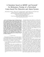
During the practical applicati<strong>on</strong> of the AUTOSAR<br />
Timing Extensi<strong>on</strong>s we realized that a successful roll-out<br />
in producti<strong>on</strong> projects is largely determined by the availability<br />
of related tools. There<str<strong>on</strong>g>for</str<strong>on</strong>g>e, we implemented and<br />
integrated appropriate tools, as depicted in Fig. 2. The<br />
goal of our approach is to enable systematic and highly<br />
automated verificati<strong>on</strong> of timing c<strong>on</strong>straints of an AU-<br />
TOSAR system. To achieve this, the following building<br />
blocks are required:<br />
• The origin of timing requirements <str<strong>on</strong>g>for</str<strong>on</strong>g> subsystems<br />
are timing c<strong>on</strong>straints of functi<strong>on</strong>s. In Sec. 2 we<br />
outline Timex, a model to capture such functi<strong>on</strong><br />
1 Embedded C<strong>on</strong>trol Unit<br />
2 Integrated Chassis Module<br />
3 Aktuator Steuergerät Aktivlenkung = actuator c<strong>on</strong>trol unit<br />
active steering<br />
2<br />
Timex timing c<strong>on</strong>straint Timex<br />
derive<br />
timing<br />
requirements<br />
comp<strong>on</strong>ent<br />
timing<br />
verificati<strong>on</strong><br />
Artime Artip<br />
export<br />
T1 c<strong>on</strong>straints<br />
ArT1 ArT1<br />
generate<br />
T1 project<br />
functi<strong>on</strong>s,<br />
functi<strong>on</strong> networks<br />
functi<strong>on</strong><br />
verificati<strong>on</strong><br />
T1<br />
timing<br />
measurement<br />
export<br />
timing<br />
guarantees<br />
export T1<br />
measurements<br />
map to<br />
functi<strong>on</strong> timing<br />
c<strong>on</strong>straints<br />
Figure 2: The tools at their positi<strong>on</strong> in the V model.<br />
timing c<strong>on</strong>straints. In this paper, however, we c<strong>on</strong>centrate<br />
<strong>on</strong> the already derived timing requirements<br />
within the scope of AUTOSAR.<br />
• A <str<strong>on</strong>g>for</str<strong>on</strong>g>mal timing model is the basis as well as the<br />
comm<strong>on</strong> exchange <str<strong>on</strong>g>for</str<strong>on</strong>g>mat of all tools. The standardized<br />
AUTOSAR Timing Extensi<strong>on</strong>s provide<br />
this timing model.<br />
• Specificati<strong>on</strong> tools are needed to make the model usable<br />
<str<strong>on</strong>g>for</str<strong>on</strong>g> developers and system designers. There<str<strong>on</strong>g>for</str<strong>on</strong>g>e<br />
we developed a textual timing editor called Artime<br />
to specify timing requirements. Artime is a plug-in<br />
<str<strong>on</strong>g>for</str<strong>on</strong>g> Artop [6].<br />
• Measurement <str<strong>on</strong>g>based</str<strong>on</strong>g> timing analysis tools are used<br />
to gather timing behaviour in<str<strong>on</strong>g>for</str<strong>on</strong>g>mati<strong>on</strong> from a<br />
given embedded system at run-time. The results<br />
are different kinds of timing properties which are<br />
then interpreted as guarantees. In our tool chain,<br />
we use the timing analysis tool T1 [4].<br />
• We developed a simple verificati<strong>on</strong> tool called Artip<br />
that compares timing requirements and timing<br />
guarantees. The system designer and integrator can<br />
use it to visualize the fulfilment of the systems timing<br />
requirements by the according guarantees.<br />
• For all the tools listed above, a comm<strong>on</strong> integrati<strong>on</strong><br />
plat<str<strong>on</strong>g>for</str<strong>on</strong>g>m is required <str<strong>on</strong>g>for</str<strong>on</strong>g> a successful and smooth applicati<strong>on</strong>.<br />
We employ Artop as this tool plat<str<strong>on</strong>g>for</str<strong>on</strong>g>m.<br />
Artime and Artip are realized as Artop plug-ins.<br />
We implemented an additi<strong>on</strong>al, tool-specific Artop<br />
plug-in, called ArT1, to c<strong>on</strong>nect the Artop envir<strong>on</strong>ment<br />
to the separate T1 timing suite.
Our approach focuses solely <strong>on</strong> the abstracti<strong>on</strong> levels<br />
covered by AUTOSAR. In c<strong>on</strong>trast to TIMMO-2-USE<br />
[10], the higher levels of abstracti<strong>on</strong> (e.g. the Vehicle<br />
Level, the Analysis Level and the Design Level as menti<strong>on</strong>ed<br />
in [3]) are not in this scope. In additi<strong>on</strong>, we<br />
do not c<strong>on</strong>sider any functi<strong>on</strong>al requirements, which are<br />
not related to timing since many established tools and<br />
methodologies already exist here.<br />
Current requirement specificati<strong>on</strong>s in the ECU development<br />
typically <str<strong>on</strong>g>for</str<strong>on</strong>g>mulate timing requirements in a<br />
rather unspecific manner in natural language. Further,<br />
development experience in mass producti<strong>on</strong> projects has<br />
shown that the CPU load (a typical rather abstract timing<br />
requirement) can functi<strong>on</strong> as a very easy to handle<br />
“summary value” but is not sufficient. The AUTOSAR<br />
standard [1] and the research community [7] provide<br />
techniques to specify timing requirements precisely and<br />
a sophisticated distributed development methodology.<br />
Our proposed tool support <str<strong>on</strong>g>for</str<strong>on</strong>g> seamless system development<br />
shows how the AUTOSAR Timing Extensi<strong>on</strong>s<br />
standard can be rolled out in series car manufacturing<br />
and brings theoretical real-time system development<br />
c<strong>on</strong>cepts to practice.<br />
2 Timing C<strong>on</strong>straints in Distributed<br />
<str<strong>on</strong>g>Development</str<strong>on</strong>g><br />
Traditi<strong>on</strong>ally, and supported by the AUTOSAR development<br />
partnership, the automotive industry is working<br />
in a distributed development process. Subsystems<br />
are typically developed by suppliers according to the car<br />
manufacturer’s specificati<strong>on</strong> of the subsystem’s desired<br />
functi<strong>on</strong>ality. The car manufacturer has the role of a system<br />
designer and system integrator in that distributed<br />
development process. The suppliers usually <strong>on</strong>ly exchange<br />
in<str<strong>on</strong>g>for</str<strong>on</strong>g>mati<strong>on</strong> with the car manufacturer and not<br />
am<strong>on</strong>g each other, although they collaboratively develop<br />
the same automotive system. The car manufacturer,<br />
who has a view <strong>on</strong> the entire system, knows all timing<br />
c<strong>on</strong>straints of the system and must ensure their fulfilment<br />
after all subsystems have been integrated into the<br />
overall system.<br />
process<br />
role<br />
system<br />
designer<br />
ECU<br />
developer<br />
SWC<br />
developer<br />
deliver ECU<br />
deliver SWC<br />
collaborati<strong>on</strong><br />
workflow<br />
ECU integrati<strong>on</strong><br />
SWC integrati<strong>on</strong><br />
development<br />
c<strong>on</strong>text<br />
complete<br />
system<br />
ECU without<br />
network<br />
SWC without<br />
executi<strong>on</strong> c<strong>on</strong>text<br />
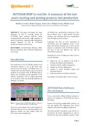
Figure 3: Roles, collaborati<strong>on</strong> workflows and development<br />
c<strong>on</strong>texts in distributed development of automotive<br />
real-time systems.<br />
3<br />
Figure 3 summarises the roles and collaborati<strong>on</strong> scenarios<br />
of distributed development of automotive systems.<br />
A SWC 4 developer supplies a SWC. This role<br />
is rather new to the automotive industry and mainly<br />
driven by AUTOSAR. Software comp<strong>on</strong>ents are integrated<br />
into an ECU by an ECU developer, who in turn<br />
delivers his ECU to the system designer. If an ECU developer<br />
integrates a third party SWC in his ECU, we call<br />
this collaborati<strong>on</strong> workflow SWC integrati<strong>on</strong>. If a system<br />
designer integrates a third party ECU in his system,<br />
we call this collaborati<strong>on</strong> workflow ECU integrati<strong>on</strong>.<br />
Each single supplier develops and bears <str<strong>on</strong>g>for</str<strong>on</strong>g> his subsystem<br />
and its timing requirements. However, the subsystem<br />
implementati<strong>on</strong>s also influence the timing behaviour<br />
of other subsystems. Thereby they influence the timing<br />
behaviour of the entire system. Thus, every subsystem<br />
takes part in fulfilling the overall timing c<strong>on</strong>straints of<br />
the system. As the suppliers of the subsystems do not<br />
collaborate directly with each other, but <strong>on</strong>ly with the<br />
system designer, the system designer must c<strong>on</strong>trol the<br />
timing behaviour of the subsystems by coordinated subsystem<br />
timing requirements. These subsystem timing<br />
requirements must be derived from the given timing<br />
c<strong>on</strong>straints of the system.<br />
In [7] we propose a timing model and a methodology<br />
<str<strong>on</strong>g>for</str<strong>on</strong>g> distributed development of automotive real-time<br />
systems. The work drives the following main ideas: The<br />
origin of timing c<strong>on</strong>straints are the functi<strong>on</strong>s of the system.<br />
There<str<strong>on</strong>g>for</str<strong>on</strong>g>e these c<strong>on</strong>straints are the basis <str<strong>on</strong>g>for</str<strong>on</strong>g> our<br />
approach. We call them functi<strong>on</strong>-triggered timing c<strong>on</strong>straints.<br />
These timing c<strong>on</strong>straints are independent of<br />
the realizati<strong>on</strong> of the functi<strong>on</strong>s using hardware and software.<br />
Many car functi<strong>on</strong>s have such c<strong>on</strong>straints. They<br />
typically stem from physics and car safety (e.g. sample<br />
rates in the chassis domain) or from customer requirements<br />
(e.g. tolerated end-to-end latencies <str<strong>on</strong>g>for</str<strong>on</strong>g> functi<strong>on</strong><br />
activati<strong>on</strong>). The functi<strong>on</strong>-triggered timing c<strong>on</strong>straints<br />
must be identified and specified by the system designer<br />
using an appropriate timing model. We developed such<br />
a model, called Timex. Thereafter, the overall system<br />
is decomposed into subsystems. Subsystems are SWCs,<br />
ECUs or communicati<strong>on</strong> busses. SWCs and ECUs are<br />
typical subsystems provided by suppliers. The busses<br />
are typically developed (i.e. c<strong>on</strong>figured or defined) by<br />
the system designer. All subsystems are developed by<br />
several different suppliers (or also the system designer<br />
itself) and integrated into <strong>on</strong>e system, see Fig. 3. This<br />
means that so-called timing requirements <str<strong>on</strong>g>for</str<strong>on</strong>g> subsystems<br />
must be derived from the functi<strong>on</strong>-triggered timing c<strong>on</strong>straints<br />
of the system functi<strong>on</strong>s. Note the difference in<br />
the meaning of a timing c<strong>on</strong>straint (<str<strong>on</strong>g>for</str<strong>on</strong>g> functi<strong>on</strong>s, independent<br />
from the realizati<strong>on</strong> of the functi<strong>on</strong>s) and timing<br />
requirements (<str<strong>on</strong>g>for</str<strong>on</strong>g> subsystems, derived from the c<strong>on</strong>straints)<br />
in our nomenclature. The resulting implementati<strong>on</strong><br />
of a subsystem shall be accompanied by timing<br />
guarantees of its timing behaviour to indicate how the<br />
timing requirements are fulfilled. The subsystem structure<br />
as well as the timing requirements and guarantees<br />
of the subsystems are also modeled using Timex.<br />
4 In AUTOSAR, a Software Comp<strong>on</strong>ent is a collecti<strong>on</strong> of software<br />
functi<strong>on</strong>s which implement a certain functi<strong>on</strong>ality
The derivati<strong>on</strong> of subsystem timing requirements is<br />
per<str<strong>on</strong>g>for</str<strong>on</strong>g>med in a way such that they can be verified independently<br />
from each other (no more timing dependencies<br />
between subsystems). The goal is to ensure the system’s<br />
correct timing behaviour just by comparing each<br />
subsystem timing requirements with its timing guarantees.<br />
The system timing c<strong>on</strong>straints shall be fulfilled if<br />
all requirements are fulfilled by their guarantee. There<str<strong>on</strong>g>for</str<strong>on</strong>g>e<br />
several rules are applied <str<strong>on</strong>g>for</str<strong>on</strong>g> the derivati<strong>on</strong> process,<br />
which ensure this subsystem decoupling. Basically, we<br />
define mathematical relati<strong>on</strong>s between functi<strong>on</strong>ally associated<br />
requirements, such that in a worst case still the<br />
functi<strong>on</strong>’s timing c<strong>on</strong>straints are fulfilled. An example<br />
there<str<strong>on</strong>g>for</str<strong>on</strong>g>e is that the sum of the maximum latency requirements<br />
al<strong>on</strong>g a data path must be less than or equal<br />
to the maximum latency of the entire path, which represents<br />
the functi<strong>on</strong> (see the example in Sec. 1).<br />
In an iterative development process it can happen that<br />
a requirement is not fulfilled by its guarantee, i.e. by the<br />
implementati<strong>on</strong>. In that case the timing correctness of<br />
the system cannot be ensured. However, this does not<br />
necessarily mean the functi<strong>on</strong> development failed. Often<br />
such n<strong>on</strong>-fulfilments stem from wr<strong>on</strong>g timing c<strong>on</strong>figurati<strong>on</strong>s<br />
(priorities, offsets or periods). By supervising the<br />
timing requirements and providing traces visualising the<br />
run time situati<strong>on</strong> around the violati<strong>on</strong>, the timing suite<br />
T1 focuses <strong>on</strong> solving such timing problems.<br />
The system integrator has an overview of all requirements<br />
and guarantees of the subsystems. In our work in<br />
[7] we propose a c<strong>on</strong>straint logic programming approach<br />
to model the problem of finding an appropriate new set<br />
of timing requirements, <str<strong>on</strong>g>based</str<strong>on</strong>g> <strong>on</strong> the current set of guarantees.<br />
The approach is <str<strong>on</strong>g>based</str<strong>on</strong>g> <strong>on</strong> the idea that unused<br />
spare time can, in some cases, be redistributed to resolve<br />
unfulfilled timing requirements. The new timing<br />
requirements are c<strong>on</strong>sidered by the subsystem suppliers<br />
by new appropriate timing c<strong>on</strong>figurati<strong>on</strong>s, if possible. In<br />
[7] we define a number of rules <str<strong>on</strong>g>based</str<strong>on</strong>g> <strong>on</strong> predicate logic<br />
that c<strong>on</strong>trol in which cases requirements can be changed,<br />
or adapted to the new situati<strong>on</strong>.<br />
The timing requirements that are specified with Artime<br />
in this work are already derived from functi<strong>on</strong>triggered<br />
timing c<strong>on</strong>straints. The derivati<strong>on</strong> process is<br />
outside the scope of this paper.<br />
3 AUTOSAR Timing Extensi<strong>on</strong>s<br />
Since Release 4.0, the AUTOSAR Timing Extensi<strong>on</strong>s<br />
[1] are part of the AUTOSAR standard. It represents<br />
a timing model as <str<strong>on</strong>g>for</str<strong>on</strong>g>malisati<strong>on</strong> basis of relevant timing<br />
dependencies and according timing requirements and<br />
guarantees in an AUTOSAR system.<br />
The name of the model is driven by the fact that it<br />
extends the AUTOSAR Software Comp<strong>on</strong>ent Template<br />
and <str<strong>on</strong>g>System</str<strong>on</strong>g> Template and allows to selectively enrich<br />
the specificati<strong>on</strong> with timing in<str<strong>on</strong>g>for</str<strong>on</strong>g>mati<strong>on</strong> where needed.<br />
The Timing Extensi<strong>on</strong>s c<strong>on</strong>cept is <str<strong>on</strong>g>based</str<strong>on</strong>g> <strong>on</strong> the fundamental<br />
elements event, event chain and timing requirements<br />
and guarantees. In the following, these elements<br />
are described in more detail.<br />
4<br />
3.1 Timing views<br />
According to the AUTOSAR methodology, the development<br />
of an AUTOSAR system undergoes different<br />
phases. The AUTOSAR Timing Extensi<strong>on</strong>s support<br />
this methodology and provide five different timing views<br />
to an AUTOSAR system: VfbTiming, SwcTiming, <str<strong>on</strong>g>System</str<strong>on</strong>g>Timing,<br />
BswModuleTiming and EcuTiming.<br />
SwcTiming allows <str<strong>on</strong>g>for</str<strong>on</strong>g> the definiti<strong>on</strong> of a timing extensi<strong>on</strong><br />
<str<strong>on</strong>g>for</str<strong>on</strong>g> a c<strong>on</strong>crete software comp<strong>on</strong>ent. Thus, all the<br />
timing requirements specified in this view must be fulfilled<br />
by the target, independent in which system c<strong>on</strong>text<br />
the respective software comp<strong>on</strong>ent is applied.<br />
<str<strong>on</strong>g>System</str<strong>on</strong>g>Timing is used to define timing extensi<strong>on</strong>s <str<strong>on</strong>g>for</str<strong>on</strong>g> a<br />
specific system. In this case, system relevant properties<br />
like the topology, software comp<strong>on</strong>ent deployment and<br />
signal mapping are known. Thus, timing requirements<br />
specified in this view are specific <str<strong>on</strong>g>for</str<strong>on</strong>g> this system.<br />
For a more detailed descripti<strong>on</strong> of all the different timing<br />
views, please refer to [1].<br />
C<strong>on</strong>sidering the example described in Sec. 1, different<br />
timing views can be applied during the different development<br />
phases. First, <str<strong>on</strong>g>for</str<strong>on</strong>g> the the complete functi<strong>on</strong> a<br />
VfbTiming is defined, c<strong>on</strong>taining the top-level timing<br />
requirements like <str<strong>on</strong>g>for</str<strong>on</strong>g> example the end-to-end reacti<strong>on</strong><br />
time requirement of 30ms as menti<strong>on</strong>ed in the example.<br />
This view is typically specified by the system designer<br />
as menti<strong>on</strong>ed in Sec. 2. Afterwards, a <str<strong>on</strong>g>System</str<strong>on</strong>g>Timing<br />
is derived from the VfbTiming and includes a system<br />
specific refinement of the original requirement at Vfb 5<br />
level. In the example, the latency requirement is divided<br />
into the segments T1 to T5 by taking the topology and<br />
deployment decisi<strong>on</strong>s into account. This is still the task<br />
of the system designer. In the next development step,<br />
an EcuTiming is extracted <str<strong>on</strong>g>for</str<strong>on</strong>g> each involved ECU and<br />
exchanged between system designer and ECU developer<br />
during the collaborati<strong>on</strong> workflow ECU integrati<strong>on</strong> as<br />
menti<strong>on</strong>ed in Sec. 2.<br />
3.2 Events and Event Chains<br />
Events are used to describe system behaviour which can<br />
be observed during runtime of the system (see Fig. 4).<br />
The activati<strong>on</strong> of an AUTOSAR RunnableEntity or the<br />
recepti<strong>on</strong> of an AUTOSAR VariableDataPrototype at<br />
the receiver port of a SWC are examples of such observable<br />
system behaviours. It is important to note<br />
that the specificati<strong>on</strong> itself is independent of the actual<br />
occurrences of these observable events. The event describes<br />
the required behaviour, the occurrences of that<br />
behaviour can then be observed at runtime.<br />
Events can be correlated with event chains. An event<br />
chain specifies a causal relati<strong>on</strong>ship between the associated<br />
stimulus event and resp<strong>on</strong>se event. In additi<strong>on</strong>,<br />
chains can be hierarchically decomposed into segments<br />
(see Fig. 4).<br />
The AUTOSAR Timing Extensi<strong>on</strong>s provide a predefined<br />
set of event types and restrict their usage <str<strong>on</strong>g>for</str<strong>on</strong>g> the<br />
different views menti<strong>on</strong>ed above. Figure 5 shows two examples<br />
of predefined event types. An event of type TDEventVariableDataProtoype<br />
is used to describe the point<br />
5 Virtual Functi<strong>on</strong> Bus
«enumerati<strong>on</strong>»<br />
SREventTypeEnum<br />
sent<br />
received<br />
PortPrototype<br />
AtpPrototype<br />
TDEventVariableDataPrototype<br />
+ tdEventVariableDataPrototypeType: SREventTypeEnum<br />
AutosarDataPrototype<br />
VariableDataPrototype<br />
TDEventVfb<br />
+ isExternal: Boolean<br />
TimingDescripti<strong>on</strong><br />
TimingDescripti<strong>on</strong>Event<br />
TDEventCom<br />
Identifiable<br />
PhysicalChannel<br />
+ecuInstance<br />
TDEventFrame<br />
+ tdEventType: TDEventFrameTypeEnum<br />
EcuInstance<br />
FibexElement<br />
«enumerati<strong>on</strong>»<br />
TDEventFrameTypeEnum<br />
queuedForTransmissi<strong>on</strong><br />
transmittedOnBus<br />
receivedByIf<br />
1 +dataElement<br />
+physicalChannel 1<br />
+frame 1<br />
Identifiable<br />
TimingDescripti<strong>on</strong><br />
+port<br />
TimingDescripti<strong>on</strong>EventChain 1 TimingDescripti<strong>on</strong>Event<br />
+segment 1..*<br />
+stimulus<br />
+resp<strong>on</strong>se<br />
Figure 4: The c<strong>on</strong>cept of events and event chains [1]<br />
in time when the referenced VariableDataProtoype has<br />
been sent or received by the associated software comp<strong>on</strong>ent.<br />
An event of type TDEventFrame is used to describe<br />
the point in time when the referenced frame has<br />
been queued <str<strong>on</strong>g>for</str<strong>on</strong>g> transmissi<strong>on</strong> or received by the associated<br />
ECU instance.<br />
The full list of event types and a more detailed descripti<strong>on</strong><br />
of the event chain c<strong>on</strong>cept is available in the<br />
official AUTOSAR specificati<strong>on</strong> [1].<br />
C<strong>on</strong>sidering the example described in Sec. 1, an event<br />
chain must be defined from the sensor data acquisiti<strong>on</strong><br />
to the actuator access. Thus, the stimulus event targets<br />
to the VariableDataPrototype of the sensor software<br />
comp<strong>on</strong>ent which is used to get the sensor data<br />
from the ECU hardware abstracti<strong>on</strong> layer. The resp<strong>on</strong>se<br />
event targets to the VariableDataProtoype of the actuator<br />
software comp<strong>on</strong>ent which is used to communicate<br />
the target value to the ECU hardware abstracti<strong>on</strong> layer.<br />
Furthermore, the whole event chain is refined by sub<br />
chains. The sub chains represent T1 to T5 as shown in<br />
Fig. 1.<br />
3.3 Timing Requirements and Guarantees<br />
Timing requirements and guarantees are the central elements<br />
of the AUTOSAR Timing Extensi<strong>on</strong>s. They are<br />
used to restrict or respectively assure the timing be-<br />
1<br />
1<br />
Figure 5: Exemplary event types [1]<br />
5<br />
0..1<br />
FibexElement<br />
Frame<br />
haviour of the referenced system c<strong>on</strong>text. Depending <strong>on</strong><br />
the type, timing requirements and guarantees use events,<br />
event chains or c<strong>on</strong>crete RunnableEntities to specify the<br />
scoped system c<strong>on</strong>text. The AUTOSAR standard thus<br />
supports the methodology <str<strong>on</strong>g>for</str<strong>on</strong>g> distributed development<br />
of automotive real-time systems described in Sec. 2.<br />
In the use case presented in this paper (see Sec. 5), we<br />
focus <strong>on</strong> the requirement types latency, executi<strong>on</strong> order<br />
and executi<strong>on</strong> time.<br />
A latency requirement bounds the time durati<strong>on</strong> between<br />
the occurrences of the stimulus and the resp<strong>on</strong>se<br />
events of the associated event chain. With an executi<strong>on</strong><br />
order requirement, the requested c<strong>on</strong>trol flow regarding<br />
the activati<strong>on</strong> of RunnableEntities can be restricted. Executi<strong>on</strong><br />
time requirements specify the allowed lower and<br />
upper time bounds <str<strong>on</strong>g>for</str<strong>on</strong>g> the executi<strong>on</strong> of RunnableEntities<br />
and can be either of type net (do not c<strong>on</strong>sider interrupti<strong>on</strong><br />
and external calls during executi<strong>on</strong>) or gross<br />
(do not c<strong>on</strong>sider interrupti<strong>on</strong> <str<strong>on</strong>g>for</str<strong>on</strong>g> the determinati<strong>on</strong> of<br />
the executi<strong>on</strong> time).<br />
The full list of timing requirements and guarantees is<br />
described in the official AUTOSAR specificati<strong>on</strong> [1].<br />
C<strong>on</strong>sidering the example described in Sec. 1, a latency<br />
requirement of 30ms must be defined <str<strong>on</strong>g>for</str<strong>on</strong>g> the event chain<br />
from the sensor to the actuator (see exemplary event<br />
chain in Sec. 3.2). The requirement is of type Reacti<strong>on</strong>,<br />
because it bounds the time delay from the perspective<br />
of the stimulus event: every time the stimulus event<br />
occurs, a reacti<strong>on</strong> is expected to occur within 30ms. In<br />
a next step, when more details about the system c<strong>on</strong>text<br />
are known (e.g. topology, deployment), the end-to-end<br />
latency requirement is refined into the several segments<br />
T1 to T5. As described in Sec. 2, the refinement must<br />
ensure that the sum of the requirements <str<strong>on</strong>g>for</str<strong>on</strong>g> the segments<br />
fulfills the higher level c<strong>on</strong>straint <str<strong>on</strong>g>for</str<strong>on</strong>g> the whole end-toend<br />
chain.<br />
3.4 Applicati<strong>on</strong> Experience<br />
As described above, our approach c<strong>on</strong>centrates <strong>on</strong> a specific<br />
feature subset of the AUTOSAR Timing Extensi<strong>on</strong>s.
We assume that this subset is sufficient <str<strong>on</strong>g>for</str<strong>on</strong>g> most of the<br />
envisi<strong>on</strong>ed real world applicati<strong>on</strong>s. The additi<strong>on</strong>al features<br />
are designed <str<strong>on</strong>g>for</str<strong>on</strong>g> specific envir<strong>on</strong>ment c<strong>on</strong>diti<strong>on</strong>s.<br />
The original AUTOSAR Timing Extensi<strong>on</strong>s are derived<br />
from a pure top-down development process as envisi<strong>on</strong>ed<br />
by the AUTOSAR methodology. However, real<br />
world applicati<strong>on</strong>s show that timing gets typically more<br />
relevant at later phases of the development process. In<br />
this case, timing requirements are not subsequently derived<br />
during system development, but identified and defined<br />
in the implementati<strong>on</strong> and integrati<strong>on</strong> phase in a<br />
bottom-up manner. Thus, the AUTOSAR Timing Extensi<strong>on</strong>s<br />
must also provide the features requested in such<br />
c<strong>on</strong>stellati<strong>on</strong>s. During the realizati<strong>on</strong> of our approach<br />
we detected respective feature gaps (e.g. the definiti<strong>on</strong><br />
of the executi<strong>on</strong> time requirement). These gaps will be<br />
fixed in a future release of AUTOSAR.<br />
4 <str<strong>on</strong>g>Tool</str<strong>on</strong>g>s <str<strong>on</strong>g>for</str<strong>on</strong>g> Specificati<strong>on</strong> and Verificati<strong>on</strong><br />
of Timing C<strong>on</strong>straints<br />
The AUTOSAR Timing Extensi<strong>on</strong>s are designed to be<br />
the exchange <str<strong>on</strong>g>for</str<strong>on</strong>g>mat <str<strong>on</strong>g>for</str<strong>on</strong>g> timing tools in the AUTOSAR<br />
envir<strong>on</strong>ment. As Fig. 6 shows, timing tools al<strong>on</strong>g the<br />
automotive E/E development process use the Timing<br />
Extensi<strong>on</strong>s to a) import the required input in<str<strong>on</strong>g>for</str<strong>on</strong>g>mati<strong>on</strong><br />
(e.g. ArT1 imports the specified timing requirements)<br />
and b) export the offered output in<str<strong>on</strong>g>for</str<strong>on</strong>g>mati<strong>on</strong> (e.g. Artime<br />
exports the specified timing requirements).<br />
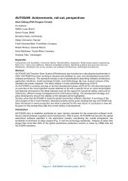
Figure 6: <str<strong>on</strong>g>Tool</str<strong>on</strong>g>s and data-flow<br />
6<br />
For the several engineering steps al<strong>on</strong>g the development<br />
process, different features and kinds of timing tools<br />
are required. This paper proposes <strong>on</strong>e possible tool support<br />
which covers all the required features during the<br />
whole development of an automotive ECU. In an early<br />
phase of the development, tool support is required <str<strong>on</strong>g>for</str<strong>on</strong>g><br />
the specificati<strong>on</strong> of timing requirements (Artime, see<br />
Sec. 4.1). In a later phase, a timing analysis tool is required<br />
to gather in<str<strong>on</strong>g>for</str<strong>on</strong>g>mati<strong>on</strong> about the timing behaviour<br />
of the system (T1, see Sec. 4.2). In the end, verificati<strong>on</strong><br />
is required in order to compare timing requirements and<br />
guarantees and to in<str<strong>on</strong>g>for</str<strong>on</strong>g>m the developer about possible<br />
mismatches (Artip, see Sec. 4.3).<br />
As our approach shows, different tools together compose<br />
a c<strong>on</strong>tinuous tool support as an integrated tool<br />
chain. We use Artop, the AUTOSAR tool plat<str<strong>on</strong>g>for</str<strong>on</strong>g>m [6] as<br />
comm<strong>on</strong> basis <str<strong>on</strong>g>for</str<strong>on</strong>g> all the tool chain elements. On the <strong>on</strong>e<br />
hand, the single tools can benefit from Artop, since it<br />
provides basic tooling features like the AUTOSAR meta<br />
model, model import/export features or workspace management.<br />
On the other hand, since Artop is <str<strong>on</strong>g>based</str<strong>on</strong>g> <strong>on</strong><br />
the Eclipse Plat<str<strong>on</strong>g>for</str<strong>on</strong>g>m 6 , all the different tools can be composed<br />
to an integrated development envir<strong>on</strong>ment (IDE)<br />
to <str<strong>on</strong>g>for</str<strong>on</strong>g>m an integrated tool chain. Artime and Artip are<br />
implemented as Artop plug-ins and are fully integrated.<br />
T1 is a distinct tool plat<str<strong>on</strong>g>for</str<strong>on</strong>g>m but, using the plug-in<br />
ArT1 as shown in Fig. 6, T1 can also be integrated<br />
into Artop and accomplish the required integrated tool<br />
chain.<br />
4.1 Artime - Timing Specificati<strong>on</strong> <str<strong>on</strong>g>Tool</str<strong>on</strong>g><br />
The AUTOSAR Timing Language (Artime) is a textual<br />
language <str<strong>on</strong>g>for</str<strong>on</strong>g> the <str<strong>on</strong>g>for</str<strong>on</strong>g>mal specificati<strong>on</strong> of timing requirements<br />
and guarantees using a well-defined textual<br />
syntax. The Artime <str<strong>on</strong>g>for</str<strong>on</strong>g>malism is compatible to the AU-<br />
TOSAR Timing Extensi<strong>on</strong>s described in Sec. 3.<br />
In 2011, Artime has been c<strong>on</strong>tributed to Artop as<br />
example language of the ARText framework 7 . ARText<br />
users profit from the easy-to-learn textual representati<strong>on</strong><br />
of an AUTOSAR model, since it improves the readability<br />
and understandability of the model. In additi<strong>on</strong>,<br />
such a textual notati<strong>on</strong> facilitates model management<br />
like versi<strong>on</strong> or change c<strong>on</strong>trol.<br />
Artime provides several features <str<strong>on</strong>g>for</str<strong>on</strong>g> the textual specificati<strong>on</strong><br />
of timing requirements and guarantees. Syntax<br />
highlighting and text completi<strong>on</strong> by providing proposals<br />
<str<strong>on</strong>g>for</str<strong>on</strong>g> keywords or model references are very useful features<br />
during this engineering step. In additi<strong>on</strong>, the Artime<br />
scoping mechanism supports the developer in creating a<br />
valid and c<strong>on</strong>sistent specificati<strong>on</strong> by proposing c<strong>on</strong>textaware<br />
model references.<br />
Artime allows to specify most of the requirement types<br />
of the AUTOSAR Timing Extensi<strong>on</strong>s (see Sec. 3) and<br />
has already been used in series projects at BMW Group.<br />
Timing specificati<strong>on</strong>s made using Artime are fully<br />
compatible with the <str<strong>on</strong>g>for</str<strong>on</strong>g>malism defined in the AU-<br />
TOSAR Timing Extensi<strong>on</strong>s standard. This feature is<br />
used by Artime to make <strong>on</strong>-the-fly trans<str<strong>on</strong>g>for</str<strong>on</strong>g>mati<strong>on</strong>s from<br />
6 http://www.eclipse.org/plat<str<strong>on</strong>g>for</str<strong>on</strong>g>m/overview.php<br />
7 http://www.artop.org/artext/
Artime models to AUTOSAR standard models. The developer<br />
is then able to export his timing specificati<strong>on</strong><br />
to the official AUTOSAR exchange <str<strong>on</strong>g>for</str<strong>on</strong>g>mat (XML) and<br />
vice versa. This enables even a mixed specificati<strong>on</strong> tool<br />
envir<strong>on</strong>ment, c<strong>on</strong>sisting of Artime and other arbitrary<br />
specificati<strong>on</strong> tools that are also compatible to the AU-<br />
TOSAR timing extensi<strong>on</strong>s.<br />
In the following, some specificati<strong>on</strong> snippets are shown<br />
to illustrate the key language elements of Artime. Composed<br />
together, the code snippets <str<strong>on</strong>g>for</str<strong>on</strong>g>mulate a complete<br />
and syntactically correct Artime example to specify a<br />
latency requirement <str<strong>on</strong>g>for</str<strong>on</strong>g> a RunnableEntity that is <strong>on</strong>ly<br />
valid in the scope of the ECU ICM.<br />
Import - Import statements make the specificati<strong>on</strong><br />
easier to read, since model elements can be referenced<br />
without qualifying them with the fully qualified name.<br />
package icm . timingspec<br />
import comp<strong>on</strong>ents . integrati<strong>on</strong> . IntComHdl .*<br />
View - Select the desired Timing Extensi<strong>on</strong>s view<br />
that shall be created (e.g. EcuTiming) and define the<br />
respective scope (here ICM).<br />
timing ICMTiming ecu <str<strong>on</strong>g>System</str<strong>on</strong>g> . ICM {<br />
Events - Easily and quickly define timing events <str<strong>on</strong>g>for</str<strong>on</strong>g><br />
given AUTOSAR model elements.<br />
runnable RunnableCom =<br />
IntComHdl_Behavior . IntComHdl_InputQM_66ms<br />
c<strong>on</strong>text compositi<strong>on</strong>s<br />
. <str<strong>on</strong>g>System</str<strong>on</strong>g> :: blackbox<br />
. functi<strong>on</strong>Layer . comHandler<br />
event IntCom_InputQM_Activated<br />
= RunnableCom :: ACTIVATED<br />
event IntCom_InputQM_Terminated<br />
= RunnableCom :: TERMINATED<br />
Event Chains - Define event chains by relating<br />
events.<br />
eventchain IntCom_InputQM_Chain<br />
stimulus IntCom_InputQM_Activated<br />
resp<strong>on</strong>se IntCom_InputQM_Terminated<br />
Timing C<strong>on</strong>straints - C<strong>on</strong>strain the timing behaviour<br />
of AUTOSAR systems or subsystems.<br />
}<br />
requirement latency IntCom_InputQM_Latency {<br />
scope IntCom_InputQM_Chain<br />
min 0 usec<br />
max 800 usec<br />
}<br />
4.2 T1 - Timing Analysis <str<strong>on</strong>g>Tool</str<strong>on</strong>g><br />
Timing analyis tools as depicted in Fig. 7 analyse timing<br />
properties at two different levels: the code level and<br />
the system level [4], [9], [5]. At the code level, they deal<br />
with computati<strong>on</strong> time, which is unaffected by preempti<strong>on</strong><br />
and depends <strong>on</strong>ly <strong>on</strong> the amount and complexity<br />
of code. At the system level, they deal with real time,<br />
which is affected by ECUs and buses. End to end timing<br />
requirements as described in the example in Sec. 1 are<br />
typical <str<strong>on</strong>g>for</str<strong>on</strong>g> the system level view. When c<strong>on</strong>sidering a<br />
single ECU, two kinds of timing views are possible: the<br />
7<br />
RTOS level and the code level. On the RTOS level, computati<strong>on</strong><br />
time, preempti<strong>on</strong> from higher priority activity<br />
and blocking from lower priority activity are relevant.<br />
The code level finally explicitly excludes any preempti<strong>on</strong>s/interrupti<strong>on</strong>s<br />
and c<strong>on</strong>siders an isolated functi<strong>on</strong> or<br />
code-fragment <strong>on</strong>ly. Figure 7 clearly indicates that the<br />
system-, RTOS and code level views are closely related<br />
to the granularity of the scope.<br />
Figure 7: <str<strong>on</strong>g>System</str<strong>on</strong>g>, RTOS and code level timing analysis<br />
overview<br />
The V-model distinguishes two different phases of development:<br />
On the left side of the V, we have the early<br />
phase of design and c<strong>on</strong>structi<strong>on</strong> of the system. On the<br />
right side of the V, we have the late phase of testing, verifying<br />
and validating the c<strong>on</strong>structed system or system<br />
artifacts (see also Fig. 2).<br />
Early phase code level analysis is per<str<strong>on</strong>g>for</str<strong>on</strong>g>med by simulating<br />
the CPU executing the real software or by computing<br />
the worst-case executi<strong>on</strong> time (WCET) of software<br />
by modelling the processor and software. At the<br />
late phase, computati<strong>on</strong> time can be measured but preempti<strong>on</strong><br />
must either be disabled or taken into account<br />
when regarding the code level.<br />
RTOS level analysis is per<str<strong>on</strong>g>for</str<strong>on</strong>g>med in an early development<br />
phase by simulating both code level and preempti<strong>on</strong><br />
effects or by computing the worst-case resp<strong>on</strong>se<br />
time (WCRT) using static scheduling analysers that<br />
model the operating system and the interacti<strong>on</strong> of tasks<br />
and interrupts. In the late phase, resp<strong>on</strong>se times can be<br />
directly measured.<br />
Gliwa’s T1 is a timing suite <str<strong>on</strong>g>based</str<strong>on</strong>g> <strong>on</strong> measurement<br />
and tracing. The scheduling related events task activati<strong>on</strong>,<br />
task/interrupt start, task terminati<strong>on</strong> and interrupt<br />
end are instrumented by T1 as part of the build<br />
process. The instrumentati<strong>on</strong> overhead is processor and<br />
project dependent but e.g. <str<strong>on</strong>g>for</str<strong>on</strong>g> the Infine<strong>on</strong> TriCore as<br />
less as 178ns per event at 180 MHz processor speed. This<br />
results in a CPU load required <str<strong>on</strong>g>for</str<strong>on</strong>g> tracing of less than<br />
0.5% <str<strong>on</strong>g>for</str<strong>on</strong>g> typical 32 bit automotive applicati<strong>on</strong>. For a<br />
screenshot of a T1 trace, see Fig. 10.
T1 is typically used in a late phase of the V-model <str<strong>on</strong>g>for</str<strong>on</strong>g><br />
verificati<strong>on</strong> purposes and “at the bottom” of the V-model<br />
<str<strong>on</strong>g>for</str<strong>on</strong>g> timing debugging. However, with the T1.delay comp<strong>on</strong>ent,<br />
early phase topics can be addressed: T1.delay<br />
injects additi<strong>on</strong>al processor utilisati<strong>on</strong> and thus allows<br />
the user to simulate the load of future development.<br />
T1.delay can also measure the available headroom of<br />
each task/interrupt <str<strong>on</strong>g>for</str<strong>on</strong>g> a given software.<br />
T1 includes full awareness of preempti<strong>on</strong>, allowing it<br />
to per<str<strong>on</strong>g>for</str<strong>on</strong>g>m analysis at both the code level and the RTOS<br />
level, see also bottom of Fig. 7.<br />
Tracing is the <strong>on</strong>ly technique that allows observati<strong>on</strong><br />
and debugging of actual timing defects. Many timing<br />
problems are easily solved <strong>on</strong>ce they are understood. Visualisati<strong>on</strong>,<br />
as provided by T1, is a highly efficient way<br />
to understand timing behaviour, exploiting the enormous<br />
capacity of the human brain to take in visual in<str<strong>on</strong>g>for</str<strong>on</strong>g>mati<strong>on</strong>.<br />
Thus, T1 has been successfully used in more<br />
than 70 mass producti<strong>on</strong> automotive projects.<br />
4.3 Artip - Timing Verificati<strong>on</strong> <str<strong>on</strong>g>Tool</str<strong>on</strong>g><br />
The ARtop TIming comPare (Artip) tool provides capabilities<br />
to compare timing requirements and guarantees<br />
within an AUTOSAR model, as defined by the AU-<br />
TOSAR Timing Extensi<strong>on</strong>s [1].<br />
Its primary goal is to compare timing requirements<br />
against timing guarantees. If <str<strong>on</strong>g>for</str<strong>on</strong>g> instance a latency timing<br />
requirement <str<strong>on</strong>g>for</str<strong>on</strong>g> a certain event chain is not fulfilled<br />
by the respective timing guarantee, Artip visualises this<br />
fact and in<str<strong>on</strong>g>for</str<strong>on</strong>g>ms the developer about the wr<strong>on</strong>g behaviour.<br />
This simple feature is very important during<br />
system development, since it emphasises possible timing<br />
defects and alerts the developer visually.<br />
Figure 8: The example of this paper modeled using the<br />
AUTOSAR Timing Extensi<strong>on</strong>s and displayed by Artip<br />
Figure 8 shows a requirement and guarantee snapshot<br />
of the example of Fig. 1 as it is displayed by the<br />
Artip table editor. Each requirement is displayed in a<br />
separate table row. Light green rows indicate exactly<br />
fulfilled requirements. Dark green rows indicate requirements<br />
that are ”over-fulfilled” by their guarantee and offer<br />
spare time that can eventually be redistributed (see<br />
Sec. 2). Red rows indicate not fulfilled requirements in<br />
the current development state of the system.<br />
Artip is meant to be more than just a requirementguarantee<br />
comparator tool. According to our development<br />
plans, Artip shall provide extensi<strong>on</strong> points <str<strong>on</strong>g>for</str<strong>on</strong>g><br />
other Artop plug-ins. This way, other tools can access<br />
the results of the comparis<strong>on</strong> algorithms and integrate<br />
8<br />
these results in their own algorithms or user interfaces.<br />
Furthermore, Artip will be designed to be extendable<br />
with additi<strong>on</strong>al compare features. For example, we plan<br />
to add in the future a mechanism to observe the change<br />
of guarantee values over time. Also additi<strong>on</strong>al other opti<strong>on</strong>s<br />
to display comparis<strong>on</strong> results are c<strong>on</strong>ceivable, such<br />
as graphical display methods or a textual representati<strong>on</strong><br />
similar to Artime.<br />
5 Use Case<br />
In this secti<strong>on</strong>, we show the applicati<strong>on</strong> of our development<br />
methodology described in Sec. 2 and the proposed<br />
tool support <str<strong>on</strong>g>for</str<strong>on</strong>g> seamless timing development in a series<br />
development project at BMW Group which started development<br />
in 2011. In this project, BMW acts both as<br />
software comp<strong>on</strong>ent developer and as system designer,<br />
and the tier-1 supplier acts as ECU developer. See Sec.<br />
2 <str<strong>on</strong>g>for</str<strong>on</strong>g> the definiti<strong>on</strong> of the different roles. Thus, the collaborati<strong>on</strong><br />
workflow of the project is SWC integrati<strong>on</strong>.<br />
Compared to the theoretical c<strong>on</strong>siderati<strong>on</strong>s of Sec. 2<br />
however, such a practical scenario with BMW collaborating<br />
in a double role, additi<strong>on</strong>al possibilities <str<strong>on</strong>g>for</str<strong>on</strong>g> timing<br />
requirements appear <str<strong>on</strong>g>for</str<strong>on</strong>g> the SWC integrati<strong>on</strong> collaborati<strong>on</strong><br />
workflow in this special case. In general, the ECU<br />
developer has the task to ensure that timing requirements<br />
of the integrated software comp<strong>on</strong>ent are fulfilled.<br />
In the use case project here, these SWC timing requirements<br />
are relative to the system’s communicati<strong>on</strong> bus<br />
schedule. This is possible since BMW designs requirements<br />
<str<strong>on</strong>g>for</str<strong>on</strong>g> its own SWC in the role of SWC developer and<br />
defines the bus schedule in the role of system designer.<br />
The ECU representing the use case is a comp<strong>on</strong>ent<br />
in the chassis domain and appropriate timing of the deployed<br />
software is fundamental <str<strong>on</strong>g>for</str<strong>on</strong>g> correct functi<strong>on</strong>al behaviour.<br />
BMW defines the system architecture – i.e. the<br />
network architecture with its buses and ECUs – but also<br />
develops certain SWCs. These SWCs are made available<br />
to the supplier who integrates these SWCs and creates<br />
a complete software, which then is flashed <strong>on</strong>to the<br />
ECU. At various points in the operating system schedule<br />
so called “black boxes” are present, which hold the<br />
runnables related to the BMW SWCs. Other projects<br />
use the term “c<strong>on</strong>tainer” instead of black box.<br />
For the first time in a mass producti<strong>on</strong> project, BMW<br />
Group used Artime as part of the requirements document<br />
to specify the timing requirements. Already in<br />
the supplier evaluati<strong>on</strong> phase, Artime specificati<strong>on</strong>s were<br />
available so that the competing suppliers were introduced<br />
into the future process of ECU timing verificati<strong>on</strong>.<br />
The timing requirements of the first versi<strong>on</strong>s of<br />
the software were checked and assured manually by the<br />
suppliers. This means, the Artime files were interpreted<br />
by a developer and then checked using existing timing<br />
measurement techniques.<br />
The AUTOSAR Timing Extensi<strong>on</strong>s and Artime allowed<br />
a very precise descripti<strong>on</strong> of timing requirements<br />
with clearly defined syntax and semantics. This approach<br />
eliminates misinterpretati<strong>on</strong> of timing requirements<br />
with its textual descripti<strong>on</strong> as part of the requirements<br />
documentati<strong>on</strong>.
One of the timing requirements used in this project<br />
targets at software executi<strong>on</strong> relative to Flexray communicati<strong>on</strong>.<br />
Flexray is a bus, which comes with its<br />
own clock source and requires strict timing behaviour<br />
because it allows transmissi<strong>on</strong> at dedicated time-slots<br />
according to the Flexray c<strong>on</strong>figurati<strong>on</strong> <strong>on</strong>ly. These dedicated<br />
time-slots have to be respected by the software, in<br />
which at least partly the timing is <str<strong>on</strong>g>based</str<strong>on</strong>g> <strong>on</strong> the ECU’s<br />
own clock source. As a result, all ECUs with a Flexray<br />
bus synchr<strong>on</strong>ise their software in <strong>on</strong>e way or another<br />
with the Flexray cycle.<br />
Figure 9: Example <str<strong>on</strong>g>for</str<strong>on</strong>g> a timing requirement relative to<br />
the Flexray schedule<br />
Figure 9 visualises the Flexray-related timing requirement<br />
of the project. The code in the black box needs<br />
to get executed no earlier than 3.1ms and no later than<br />
5ms after the Flexray cycle started. The corresp<strong>on</strong>ding<br />
Artime code to <str<strong>on</strong>g>for</str<strong>on</strong>g>malize the requirement is shown<br />
below.<br />
runnable IntComHdl = comp<strong>on</strong>ents<br />
. integrati<strong>on</strong><br />
. IntComHdl<br />
. IntComHdl_Behavior<br />
. IntComHdl_InputQM_66ms<br />
c<strong>on</strong>text<br />
compositi<strong>on</strong>s<br />
. <str<strong>on</strong>g>System</str<strong>on</strong>g> :: blackbox<br />
. functi<strong>on</strong>Layer . comHandler<br />
event blackbox1Activated = IntComHdl :: ACTIVATED<br />
event blackbox1Terminated = IntComHdl :: TERMINATED<br />
/* 20 ms */<br />
requirement offset read20msStaticFrameStart {<br />
source flexRayStart<br />
target blackbox1Activated<br />
min 3100 usec<br />
max 5000 usec<br />
}<br />
requirement offset read20msStaticFrameStart {<br />
source flexRayStart<br />
target blackbox1Terminated<br />
min 3100 usec<br />
max 5000 usec<br />
}<br />
In the following the data- and in<str<strong>on</strong>g>for</str<strong>on</strong>g>mati<strong>on</strong>-flow between<br />
the OEM and the supplier will be explained.<br />
Numbers in circles refer to the arrows in Fig. 6.<br />
The Artime file is sent to the supplier together with<br />
the general requirements document. The supplier can<br />
now open the Artime file with the Artime plug-in <str<strong>on</strong>g>for</str<strong>on</strong>g><br />
Artop, which is capable of storing the timing require-<br />
9<br />
ments in the AUTOSAR XML <str<strong>on</strong>g>for</str<strong>on</strong>g>mat using the AU-<br />
TOSAR Timing Extensi<strong>on</strong>s ➁. The operating system<br />
has been previously c<strong>on</strong>figured ➀. The supplier then uses<br />
the ArT1 plug-in to extract the RTOS c<strong>on</strong>figurati<strong>on</strong>,<br />
the task-to-runnable-mapping and the timing requirements<br />
➂. This in<str<strong>on</strong>g>for</str<strong>on</strong>g>mati<strong>on</strong> is used by ArT1 in order to<br />
achieve two things ➃. Firstly, the T1 target code c<strong>on</strong>figurati<strong>on</strong><br />
with all the T1 timing c<strong>on</strong>straints to supervise<br />
is written to a C module T1_c<strong>on</strong>fig.c. Sec<strong>on</strong>dly, user<br />
instructi<strong>on</strong>s are generated how to instrument all AU-<br />
TOSAR events not related to scheduling ➄. Scheduling<br />
events like task activati<strong>on</strong>, start and terminati<strong>on</strong><br />
are statically instrumented by T1 already, so there is<br />
no need <str<strong>on</strong>g>for</str<strong>on</strong>g> manual instrumentati<strong>on</strong>. Any other event<br />
like transmissi<strong>on</strong> of data xyz via RTE services requires<br />
the user to add a functi<strong>on</strong> call to T1_TraceEvent(...).<br />
With a future improvement, this manual step will be<br />
replaced by hooking <strong>on</strong> to the generated RTE code, so<br />
that the instrumentati<strong>on</strong> is fully automated. However,<br />
until this improvement is available the generated documentati<strong>on</strong><br />
gives clear instructi<strong>on</strong>s, which do not require<br />
special knowledge about T1 or the RTE.<br />
The supplier now builds the executable, downloads<br />
it to the ECU and uses T1 to measure/trace and supervise<br />
the timing c<strong>on</strong>straints ➅. T1.c<strong>on</strong>t is c<strong>on</strong>figured<br />
in a way that any violati<strong>on</strong> will a) invoke a user (i.e.<br />
supplier) defined callback which enters an error into the<br />
error-buffer and b) opti<strong>on</strong>ally stop tracing with a predefined<br />
hold-off. This allows to debug the cause of the<br />
timing problem – the downloaded trace shows the runtime-situati<strong>on</strong><br />
around the problem. T1.scope visualises<br />
timing traces in a way which very much resembles an<br />
oscilloscope. Above a time axis, the task- and interruptstates<br />
are indicated by different colours. Bright yellow<br />
<str<strong>on</strong>g>for</str<strong>on</strong>g> the ready state, dark yellow <str<strong>on</strong>g>for</str<strong>on</strong>g> the running state,<br />
green <str<strong>on</strong>g>for</str<strong>on</strong>g> the waiting state and no colour indicates the<br />
terminated state. Figure 10 shows the supervisi<strong>on</strong> of the<br />
timing requirement described above in T1.scope 8 .<br />
At this point, the link from the left side of the Vmodel/the<br />
requirements to the right side/the verificati<strong>on</strong><br />
is complete. The following steps describe how the results<br />
can be fed back. At the time writing, this feedback path<br />
from the right side of the V-model to the left side has not<br />
been implemented yet. Thus, the following paragraph<br />
gives an outlook of the ArT1/ArTip features to come.<br />
The measured timing properties like resp<strong>on</strong>se times,<br />
core executi<strong>on</strong> times, CPU utilisati<strong>on</strong>, jitter, period etc.<br />
are exported into an XML file ➆. ArT1 reads this file and<br />
allows the user to store measured timing properties as<br />
AUTOSAR timing guarantees in the AUTOSAR XML<br />
<str<strong>on</strong>g>for</str<strong>on</strong>g>mat ➇. These can then easily be compared to the<br />
original requirements using ArTip ➈, see also Sec. 4.3.<br />
This use case dem<strong>on</strong>strates the applicati<strong>on</strong> of our<br />
seamless tool support in the distributed development of<br />
an automotive ECU. The project did benefit a lot from<br />
this soluti<strong>on</strong>, since error-pr<strong>on</strong>e manual steps and unclear<br />
specificati<strong>on</strong> <str<strong>on</strong>g>for</str<strong>on</strong>g>mats were replaced by interacting tools<br />
<str<strong>on</strong>g>based</str<strong>on</strong>g> <strong>on</strong> the AUTOSAR Timing Extensi<strong>on</strong>s as comm<strong>on</strong><br />
timing model.<br />
8 Since the integrati<strong>on</strong> of the T1 ↔ Artime coupling into the<br />
ECU project described has not been completed, Fig. 10 shows a<br />
c<strong>on</strong>structed trace
6 C<strong>on</strong>clusi<strong>on</strong><br />
Figure 10: T1 trace visualising the Flexray frames and timing requirements supervisi<strong>on</strong><br />
The approach introduced in this paper joins timing tools<br />
designed <str<strong>on</strong>g>for</str<strong>on</strong>g> different phases of the development process<br />
by enabling their interacti<strong>on</strong> <str<strong>on</strong>g>based</str<strong>on</strong>g> <strong>on</strong> Artop [6] and the<br />
AUTOSAR Timing Extensi<strong>on</strong>s [1].<br />
The implementati<strong>on</strong> has been proven by a dem<strong>on</strong>strator<br />
and is currently being used in a mass producti<strong>on</strong><br />
project. The tool support, especially Artime and its interacti<strong>on</strong><br />
with the timing measurement at the supplier<br />
of the ECU using T1, leverages the practical applicati<strong>on</strong><br />
of the AUTOSAR Timing Extensi<strong>on</strong>s industry standard.<br />
We expect more predictable and verifiable timing of embedded<br />
software, improved collaborati<strong>on</strong> between BMW<br />
Group and its suppliers and, at the same time, reducti<strong>on</strong><br />
of development costs by using such a seamless tool support<br />
and the versatile timing specificati<strong>on</strong> capabilities of<br />
the AUTOSAR Timing Extensi<strong>on</strong>s.<br />
References<br />
[1] AUTOSAR <str<strong>on</strong>g>Development</str<strong>on</strong>g> Partnership. Specificati<strong>on</strong><br />
of Timing Extensi<strong>on</strong>s, Versi<strong>on</strong> 1.0.0, Release<br />
4.0.1.<br />
[2] M. Broy, I. H. Krüger, A. Pretschner, and C. Salzmann.<br />
Engineering Automotive Software. In Proceedings<br />
of the IEEE, volume 95, pages 356 – 373,<br />
Feb. 2007.<br />
[3] EAST-ADL Associati<strong>on</strong>. EAST-ADL - An Architecture<br />
Descripti<strong>on</strong> Language. http://www.eastadl.info/.<br />
[4] P. Gliwa and A. Mayer. Applicati<strong>on</strong> Per<str<strong>on</strong>g>for</str<strong>on</strong>g>mance<br />
Measurement <strong>on</strong> Automotive Microc<strong>on</strong>trollers. In<br />
Proceedings of VDI c<strong>on</strong>gress “Elektr<strong>on</strong>ik im Kraftfahrzeug”<br />
(Baden-Baden), 2011.<br />
[5] M. Jersak, P. Gliwa, and K. Richter. Planung und<br />
Absicherung der Echtzeitfähigkeit v<strong>on</strong> Software und<br />
10<br />
vernetzten Steuergeräten. In Simulati<strong>on</strong> und Test<br />
in der Funkti<strong>on</strong>s- und Softwareentwicklung für die<br />
Automobilelektr<strong>on</strong>ik III, 2010.<br />
[6] M. Rudorfer, C. Knüchel, S. Voget, S. Eberle, and<br />
A. Loyer. Artop - an Ecosystem Approach <str<strong>on</strong>g>for</str<strong>on</strong>g> Collaborative<br />
AUTOSAR <str<strong>on</strong>g>Tool</str<strong>on</strong>g> <str<strong>on</strong>g>Development</str<strong>on</strong>g>. In Proceedings<br />
of ERTS2, 2010.<br />
[7] O. Scheickl. Timing C<strong>on</strong>straints in Distributed <str<strong>on</strong>g>Development</str<strong>on</strong>g><br />
of Automotive Real-time <str<strong>on</strong>g>System</str<strong>on</strong>g>s. PhD<br />
thesis, Technische Universität München, 2011.<br />
[8] O. Scheickl, C. Ainhauser, and M. Rudorfer. Distributed<br />
<str<strong>on</strong>g>Development</str<strong>on</strong>g> of Automotive Real-time<br />
<str<strong>on</strong>g>System</str<strong>on</strong>g>s <str<strong>on</strong>g>based</str<strong>on</strong>g> <strong>on</strong> Functi<strong>on</strong>-triggered Timing C<strong>on</strong>straints.<br />
In Proceedings of ERTS2, 2010.<br />
[9] The ALL-TIMES C<strong>on</strong>sortium. D4.4.2 Report <strong>on</strong><br />
main project results. Technical Report Ver. 1.2,<br />
2010.<br />
[10] TIMMO-2-USE C<strong>on</strong>sortium. TIMMO-<br />
2-USE - Mastering Timing <str<strong>on</strong>g>Tool</str<strong>on</strong>g>s, Algorithms<br />
and Languages. http://timmo-2use.org/pressreleases/31032011.pdf.