English - Rohde & Schwarz
English - Rohde & Schwarz
English - Rohde & Schwarz

Create successful ePaper yourself
Turn your PDF publications into a flip-book with our unique Google optimized e-Paper software.
News from <strong>Rohde</strong> & <strong>Schwarz</strong><br />
In hot pursuit of the top performers:<br />
new medium-class spectrum analyzers<br />
Software-based radios<br />
for professional use<br />
Coverage measurements<br />
supported by convenient software<br />
2000/I<br />
166
The new, attractively priced FSP spectrum analyzers,<br />
though medium class, offer similar performance<br />
as the high-end instruments FSE and<br />
FSIQ. In some respects they even outdo the<br />
top performers. With their high measurement<br />
speed and accuracy, the FSP analyzers are<br />
not only the right tool for general-purpose<br />
laboratory and service applications but also<br />
the ideal choice for production environments<br />
(page 4).<br />
Articles<br />
Josef Wolf<br />
Michael Fraebel;<br />
Robert Vielhuber<br />
Wolfgang Kernchen<br />
Günter Huber;<br />
Stefan Ritthaler<br />
Franz Demmel;<br />
Ulrich Unselt<br />
Elke Schulze;<br />
Günther Zurek-Terhardt<br />
Application notes<br />
Heinz-Peter Olbrück<br />
Burkhard Küfner;<br />
Dr Rene Desquiotz<br />
Wilhelm Kraemer<br />
Michael Manert<br />
Photo 43 516<br />
2 News from <strong>Rohde</strong> & <strong>Schwarz</strong> Number 166 (2000/I)<br />
Number 166 2000/I Volume 40<br />
Spectrum Analyzer FSP<br />
Medium class aspiring to high end.......................................................... 4<br />
Series 4400<br />
Software-based radios for professional use............................................... 8<br />
Signal Generator SMIQ<br />
Fit for 3G with new options .................................................................. 10<br />
TV Test Transmitter SFQ<br />
SFQ goes North American – with digital TV standard ATSC ..................... 13<br />
Digital Direction Finder DDF190<br />
Now from 0.5 MHz through 3000 MHz................................................ 16<br />
Web over DTV – Cost-attractive service through DVB:<br />
Transmission of extra data in Web format............................................... 18<br />
Content Management System eidonXbase<br />
Database-supported information management ........................................ 20<br />
I/Q Modulation Generator AMIQ<br />
New models 03 and 04 as well as digital I/Q output option.................... 22<br />
Microwave Signal Generator SMR<br />
SMR as tracking generator for Vector Network Analyzer ZVM.................. 24<br />
Calculating measurement uncertainty<br />
of conformance test systems for mobile phones ....................................... 26
Johann Maier;<br />
Andreas Spachtholz<br />
Ralf Dittmar<br />
Thomas Reichel<br />
Alexander Wörner<br />
Stefan Böttinger<br />
Roland Minihold<br />
Monika Roth<br />
Web over DTV is a simple and cost-effi cient<br />
solution for distributing Internet resources<br />
among TV viewers, for example, or for allowing<br />
TV providers to offer additional services<br />
with their programs. This service is implemented<br />
by means of the <strong>Rohde</strong>&<strong>Schwarz</strong><br />
DTV IP Inserter and the DTV Web Carousel<br />
software (page 18).<br />
Software<br />
Coverage Measurement Software ROMES 3 – Acquisition, analysis<br />
and visualization of data in coverage measurements ............................... 29<br />
Encryption Software SafeIT<br />
Sensitive data? Play it safe ................................................................... 34<br />
Panorama<br />
Power Refl ection Meter NRT<br />
Fit for 3G digital mobile radio .............................................................. 36<br />
Optimizing digital TV networks – QoS maintained automatically .............. 38<br />
Regular features<br />
CD-ROM: Exploring the world of mobile-radio tester CMU ....................... 28<br />
Test hint: Enhanced accuracy in BER measurements<br />
by precise level calibration of CMD ....................................... 33<br />
In brief: Have a go – puzzle competition on the Internet with<br />
individualized main prize ..................................................... 39<br />
Information in print.............................................................................. 40<br />
Press comments....................................................................................41<br />
Newsgrams.........................................................................................41<br />
Imprint<br />
Published by ROHDE&SCHWARZ GmbH&Co. KG · Muehldorfstrasse 15 · 81671 Munich · Support<br />
Center: Tel. (+49) 01805124242 · E-mail: customersupport@rohde-schwarz.com · Fax (+4989)<br />
4129-3777 · Editor and layout: Ludwig Drexl, Redaktion – Technik (German) · <strong>English</strong> translation:<br />
Dept. 5CL4 · Photos: Stefan Huber · Circulation 90000 · ISSN 0028-9108 · Supply free of charge<br />
through your nearest <strong>Rohde</strong>&<strong>Schwarz</strong> representative · Printed in Germany by peschke druck, Munich<br />
Reproduction of extracts permitted if source is stated and copy sent to <strong>Rohde</strong>&<strong>Schwarz</strong> Munich.<br />
News from <strong>Rohde</strong> & <strong>Schwarz</strong> Number 166 (2000/I) 3
Photo 43 446<br />
Articles<br />
Spectrum Analyzer FSP<br />
Medium class aspiring to high end<br />
Playing right at the top of the high-end class are Spectrum Analyzers FSE and<br />
Signal Analyzers FSIQ from <strong>Rohde</strong> & <strong>Schwarz</strong>. After all, their RF performance,<br />
measurement speed and accuracy plus fl exibility make them suitable for even<br />
the most demanding applications. New on the scene are the attractively priced<br />
Spectrum Analyzers FSP (FIG 1) that, although medium class, are able to offer<br />
similar performance. And in some respects they even outdo the top performers.<br />
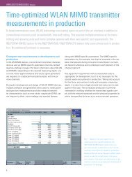
High measurement accuracy<br />
combined with high speed<br />
With its high measurement speed and<br />
accuracy, FSP is not only the right<br />
tool for general-purpose laboratory<br />
and service applications but also an<br />
ideal choice for production needs.<br />
Speed and accuracy are decisive for<br />
throughput and for investment in measuring<br />
equipment for a given production<br />
target. To signifi cantly improve<br />
these key features, <strong>Rohde</strong> & <strong>Schwarz</strong><br />
took a completely new approach in<br />
the design of FSP, making it fi t for inproduction<br />
measurements, for example<br />
on components and modules of radio<br />
transmission equipment, with maximum<br />
speed and reproducibility.<br />
The basic prerequisite for high measurement<br />
throughput is high-speed remote<br />
control. A normal benchmark test determines<br />
the number of traces transmit-<br />
4 News from <strong>Rohde</strong> & <strong>Schwarz</strong> Number 166 (2000/I)<br />
ted per second to a controller on the<br />
remote interface. FSP is fi tted with an<br />
IEC/IEEE-bus interface as stan dard.<br />
With 10 MHz span and minimum<br />
sweep time it transmits up to 30 traces<br />
with 501 test points per trace. In the<br />
zero span mode, as many as 70 traces<br />
per second are possible. In manual<br />
operation, up to 25 pictures per second<br />
create the impression of an analog<br />
measurement and enable speedy alignment.<br />
The FSP family comprises four analyzers with<br />
different frequency ranges:<br />
FSP3 9 kHz to 3 GHz<br />
FSP7 9 kHz to 7 GHz<br />
FSP13 9 kHz to 13 GHz<br />
FSP30 9 kHz to 30 GHz<br />
Thus optimum frequency range can be offered<br />
for each application, whether RF or microwave.<br />
FIG 1 FSP (front, as cabinet for portable use) is approaching high-end<br />
units (FSE and FSIQ in background) in performance<br />
Synthesizer set in next<br />
to no time<br />
A VCO works as the fi rst local oscillator.<br />
This offers considerably higher speed<br />
than the usual magnetically tuned YIG<br />
oscillator because it can be set much<br />
faster. You notice it in particular when<br />
resetting the frequency between two<br />
frequency scans. The sweep oscillator<br />
is always synchronized to the reference<br />
frequency, which results in<br />
excellent frequency accuracy even<br />
with large spans. The minimum sweep<br />
time of FSP is 2.5 ms. Plus, the FSP<br />
synthesizer features extremely low<br />
phase noise. The guaranteed fi gure at<br />
500 MHz and 10 kHz carrier offset is<br />
–106 dBc(1 Hz). Typically, a fi gure as<br />
low as –110 dBc(1 Hz) is obtained<br />
(FIG 2). These good phase noise characteristics<br />
are maintained up to 7 GHz<br />
input frequency because there is no<br />
doubling of the oscillator frequency.
Phase noise/dBc(1Hz)<br />
–90<br />
–100<br />
–110<br />
–120<br />
–130<br />
1 10 100 1000<br />
Frequency offset/kHz<br />
FIG 2 Phase noise of Spectrum Analyzer FSP at 500 MHz, measured<br />
on 10 units<br />
Digital signal processing<br />
Other important features contributing to<br />
the high measurement speed of FSP are<br />
the high sampling rate (32 MHz) for<br />
FIG 4 Adjacent-channel power measurement<br />
to IS-95 CDMA in time domain (Fast ACP). Measurements<br />
to this standard, for example, require<br />
a sweep time of approx. 800 ms when using<br />
the integration method so far common in spectrum<br />
analyzers, to be able to detect the power<br />
in the transmit channel and in two adjacent<br />
channels (above and below the transmit channel)<br />
with 0.25 dB standard deviation. Using the<br />
measurement method of FSP in the time domain,<br />
only 50 ms is required. Time overheads caused<br />
by frequency switchover, internal calculations<br />
and output of results via IEC/IEEE bus are only<br />
approx. 30 ms, so reproducible results are available<br />
within 80 ms.<br />
Anti-aliasing<br />
bandpass 12 bit<br />
IF<br />
A<br />
20.4 MHz<br />
D<br />
the last IF voltage or video voltage, and<br />
processing of the digitized signals in<br />
R&S-developed ASICs. So sweep times<br />
between 1 µs and 16000 s are possible<br />
at zero span. This concept benefi ts<br />
not only measurement speed but also<br />
accuracy and reproducibility.<br />
To maximize measurement speed and<br />
simplify manual operation, FSP features<br />
internal routines, running markedly<br />
faster using the internal sequences<br />
than with external control. Frequent<br />
measurements in development, verifi -<br />
cation and production are those of<br />
power and adjacent-channel power<br />
on TDMA or CDMA signals for example.<br />
Here FSP offers preconfi gured,<br />
particularly fast test routines for the<br />
major standards (W-CDMA, cdmaOne,<br />
IS-136 and TETRA).<br />
Digital resolution fi lters are implemented<br />
for bandwidths between 10 Hz<br />
and 30 kHz (FIG 3). Switchover<br />
between the fi lters is effected by loading<br />
the corresponding coeffi cients into<br />
the ASIC. This digital implementation<br />
of the IF bandwidths not only allows<br />
use of Gaussian fi lters, common in<br />
spectrum analyzers, but also of steep<br />
channel fi lters and even root-cosine<br />
fi lters, stipulated by different standards<br />
for measuring channel and adjacentchannel<br />
power.<br />
IF<br />
32 MHz<br />
IF<br />
Q mixer<br />
LO<br />
I mixer<br />
LO<br />
90˚<br />
NCO<br />
FIG 3 Block diagram of digital fi lters in FSP<br />
I<br />
Q<br />
Digital resolution<br />
bandwidths<br />
Filter coeff.<br />
Filter coefficients<br />
Articles<br />
I 2 + Q 2<br />
IF<br />
envelope<br />
The digital concept is utilized in FSP<br />
to measure adjacent-channel power<br />
in the time domain. The FSP family<br />
comes with channel fi lters for the<br />
most common standards, including<br />
W-CDMA. For power detection there<br />
is the rms detector familiar from the<br />
FSE family. FSP sets the different channel<br />
frequencies one after the other<br />
according to the selected standards,<br />
and mea sures the power at each frequency<br />
using the specifi ed channel<br />
fi lters. Because of the fast VCO synthesizer,<br />
the time required for channel<br />
frequency switchover is virtually insignifi<br />
cant. Using this method, measurements<br />
are speeded up by a factor of<br />
about 10 compared to the integration<br />
method common to date in spectrum<br />
analyzers (FIG 4).<br />
News from <strong>Rohde</strong> & <strong>Schwarz</strong> Number 166 (2000/I) 5<br />
Photo 43 389/10
Articles<br />
Deviation/dB<br />
1<br />
0.8<br />
0.6<br />
0.4<br />
0.2<br />
0<br />
–0.2<br />
–0.4<br />
–0.6<br />
–0.8<br />
–1<br />
0 500 1000 1500 2000 2500 3000<br />
Input frequency/MHz<br />
FIG 5 Frequency response of FSP up to 3 GHz, measured on 10 units at<br />
0/25/50°C. Red tolerance lines mark guaranteed limit values specifi ed in<br />
data sheet. Calculated standard deviation of results is 0.135 dB<br />
Measurement uncertainty<br />
reduced to a minimum<br />
In FSP, <strong>Rohde</strong> & <strong>Schwarz</strong> presents for<br />
the fi rst time a spectrum analyzer with<br />
a guaranteed total measurement uncertainty<br />
as small as 0.5 dB in the main<br />
communication range up to 3 GHz,<br />
and this over the specifi ed temperature<br />
range, for all RF attenuator settings and<br />
with 70 dB level range on the display.<br />
Due to the high measurement accuracy<br />
of FSP, higher tolerances can be<br />
allowed for the DUT and the number of<br />
rejects reduced, or measurement times<br />
can be reduced with correspondingly<br />
lower repeat accuracy.<br />
The outstanding precision of FSP is<br />
based on a concept that minimizes<br />
uncertainties right from the start:<br />
• digital signal processing in ASICs,<br />
• use of function modules with close<br />
tolerances, which are decisive for<br />
measurement uncertainties,<br />
• correction of residual errors by<br />
integrated fi rmware.<br />
To make it easier for the user to calculate<br />
the total measurement uncertainty,<br />
for example in a test system, the FSP<br />
data sheet for the fi rst time specifi es<br />
standard deviations of the individual<br />
uncertainties (FIGs 5 and 6).<br />
6 News from <strong>Rohde</strong> & <strong>Schwarz</strong> Number 166 (2000/I)<br />
Deviation/dB<br />
0.6<br />
0.4<br />
0.2<br />
–0.2<br />
–0.4<br />
Excellent RF performance<br />
The RF performance of an analyzer<br />
is a decisive criterion as to whether<br />
complex measurements, for example<br />
of intermodulation or spurious, can be<br />
performed for a given DUT. Depending<br />
on the demands made for RF performance,<br />
a high-end spectrum analyzer<br />
like FSE or a medium-class instrument<br />
like FSP will be used. While FSP is not<br />
comparable with FSE or FSIQ in terms<br />
of RF performance, it excels in sensitivity<br />
and large-signal characteristics for<br />
an instrument of the medium class.<br />
Sensitivity is usually specifi ed as displayed<br />
average noise level (DANL)<br />
at the smallest resolution bandwidth.<br />
FSP achieves < –140 dBm at 10 Hz<br />
resolution bandwidth up to 7 GHz.<br />
Typical fi gures are –145 dBm (10 Hz)<br />
up to 3 GHz and –143 dBm (10 Hz)<br />
from 3 GHz to 7 GHz. The FFT fi lters<br />
(1 Hz to 30 kHz) fi tted as standard<br />
not only improve DANL but also afford<br />
considerably higher speed than sweep<br />
fi lters.<br />
But overall dynamic range is determined<br />
by DANL plus large-signal characteristics.<br />
The latter depend on the<br />
power-handling capacity of the input<br />
mixer (1 dB compression) and on intermodulation.<br />
With a 1 dB compression<br />
0<br />
–0.6<br />
0 10 20 30 40 50 60 70 80 90<br />
Rel. level/dB<br />
FIG 6 Linearity error of digital bandwidth fi lters between 10 Hz and<br />
30 kHz in level range down to 90 dB below reference level, measured<br />
on 30 units. Red tolerance lines mark data sheet specifi cations (±0.2 dB<br />
down to –70 dB and ±0.5 dB below)<br />
FIG 8 Adjacent-channel power measurement<br />
on W-CDMA uplink signal shows the excellent<br />
overall dynamic range of about 64 dBc of<br />
Spectrum Analyzer FSP<br />
level of the input mixer of 0 dBm and<br />
a third-order intercept point of ≥7 dBm,<br />
FSP offers an overall dynamic range<br />
that is excellent in this medium class<br />
(FIG 7).<br />
The outstanding dynamic characteristics<br />
show, for example, in adjacentchannel<br />
power measurements on uplink<br />
W-CDMA signals to ARIB standard<br />
with an overall dynamic range of<br />
approx. 64 dBc in the fi rst adjacent<br />
channel (FIG 8).
20<br />
10<br />
0<br />
–10<br />
–30<br />
–50<br />
–70<br />
–90<br />
–110<br />
–130<br />
dBm<br />
–150<br />
FIG 7 Displayed average noise level (DANL) at 10 Hz bandwidth and<br />
third-order intercept point (TOI) measured on 10 FSP3 units<br />
Multitude of preconfigured<br />
measurement functions<br />
TOI/dBm<br />
DANL/dBm<br />
0 500 1000 1500 2000 2500 3000<br />
Frequency/MHz<br />
The FSP family comes with a large<br />
number of preconfi gured measurement<br />
functions for the wide range of applications<br />
to be covered by a spectrum<br />
analyzer (yellow box). With so many<br />
functions ready implemented, FSP‘s list<br />
of options is very short. An OCXO is<br />
available for enhanced frequency accuracy,<br />
a tracking generator for scalar<br />
network analysis up to 3 GHz, and<br />
an AM/FM demodulator with internal<br />
loudspeaker and headphones output<br />
for signal monitoring. The optional<br />
REFERENCES<br />
[1] Wolf, Josef: Spectrum Analyzer FSEA/FSEB:<br />
New dimensions in spectral analysis. News<br />
from <strong>Rohde</strong> & <strong>Schwarz</strong> (1995) No.148,<br />
pp 4–8<br />
Condensed data of FSP<br />
Frequency range (FSP3/7/13/30) 9 kHz to 3/7/13/30 GHz<br />
Amplitude measurement range –140 dBm to 30 dBm<br />
Amplitude display range 10 dB to 200 dB in steps of 10 dB, linear<br />
Amplitude measurement error limit < 0.5 dB up to 3 GHz<br />
< 2 dB from 3 GHz to 13 GHz<br />
< 2.5 dB from 13 GHz to 30 GHz<br />
Resolution bandwidths 1 Hz to 30 kHz, FFT fi lters<br />
10 Hz to 10 MHz in increments of 1 and 3<br />
EMI bandwidths 200 Hz, 9 kHz, 120 kHz,<br />
channel fi lters<br />
Detectors max peak, min peak, auto peak, sample,<br />
average, rms, quasi-peak<br />
Display 21 cm (8.4") TFT colour LC display, VGA<br />
resolution<br />
Remote control IEC 625-2 (SCPI 1997.0) or RS-232-C<br />
Dimensions (W x H x D) 412 mm x 197 mm x 417 mm<br />
Weight w/o options (FSP3/7/13/30) 10.5/11.3/12/12 kg<br />
Reader service card 166/01<br />
100-base T-LAN interface allows not<br />
only networked control of FSP but also<br />
transfer of large amounts of data from<br />
FSP‘s IQ memory (2 x 128 kwords).<br />
Noise Measurement Software FS-K3<br />
is available for measuring the noise<br />
fi gure of amplifi ers and frequency-converting<br />
components and modules. The<br />
noise source is driven direct by FSP.<br />
Josef Wolf<br />
Articles<br />
Photo 43 389/12<br />
Preconfigured test functions<br />
• Frequency counter with fast algorithm<br />
for digitally implemented<br />
bandwidths up to 30 kHz<br />
• Measurement of noise and<br />
phase noise<br />
• Measurement of AM modulation<br />
depth<br />
• Measurement of third-order<br />
intercept point (TOI)<br />
• Power measurement in time<br />
domain (mean, rms and peak<br />
power over selectable time<br />
periods)<br />
• Power measurement in frequency<br />
domain, adjacent-channel power<br />
measurement preconfi gured for<br />
major standards<br />
• Gated-sweep function<br />
• Versatile trigger functions (free<br />
run, video, external, IF power,<br />
pretrigger, trigger delay)<br />
• Signal statistics (APD/CCDF)<br />
over defi nable number of decorrelated<br />
measured values<br />
• Measurement of occupied bandwidth<br />
• EMI quasi-peak detector (bands<br />
A, B and C/D) with corresponding<br />
EMI bandwidths 200 Hz,<br />
9 kHz and 120 kHz<br />
• User-defi nable limit lines (absolute<br />
or relative) with selectable<br />
margin and pass/fail indication<br />
• Two independent test settings<br />
with fast switchover at keystroke<br />
• Split-screen display with separate<br />
settings in two measurement<br />
windows<br />
News from <strong>Rohde</strong> & <strong>Schwarz</strong> Number 166 (2000/I) 7
Photo 43465<br />
Articles<br />
Series 4400<br />
Software-based radios for<br />
professional use<br />
The new Series 4400 radio generation (M3SR for multiband, multimode, multifunction<br />
surface radio) (FIG 1) is based on a powerful uniform platform. The open<br />
system architecture surmounts the drawbacks of conventional LOS radios, characterized<br />
by different platforms and devices for various frequency bands and applications.<br />
Like its successful predecessors of Series 400U, the application range of<br />
Series 4400 radios covers air traffi c control through air defence to complex naval<br />
communication systems.<br />
Multifunctional platform<br />
Complex transmission modes, digital<br />
modulation and straightforward integration<br />
into modern networks are the<br />
demands on today’s radio systems.<br />
Plus, professional users insist on multiline<br />
capability, ie concurrent operation<br />
of several communication lines in a<br />
single radio.<br />
In Series 4400, <strong>Rohde</strong> & <strong>Schwarz</strong><br />
offers a concept that is implemented on<br />
a software-controlled, uniform platform<br />
8 News from <strong>Rohde</strong> & <strong>Schwarz</strong> Number 166 (2000/I)<br />
with very large scale integration (VLSI)<br />
modules. This principle ensures truly<br />
versatile use and an extreme measure<br />
of radio-system standardization with all<br />
the accompanying potential for reducing<br />
cost of ownership.<br />
Based on an embedded realtime operating<br />
system, the platform handles internal<br />
communication, interfaces with the<br />
outside world and takes care of AF<br />
signal processing as well as device<br />
control. Waveform modifi cations or<br />
additional data radio protocols can<br />
be implemented by simple software<br />
downloads. The customer can thus<br />
create fl exible radio systems from hardware<br />
and software building blocks.<br />
The basic platform is identical for all<br />
applications. In tune with the philosophy<br />
of a universal platform, a variety<br />
of software and hardware extensions,<br />
called preplanned product improvements<br />
(P 3 I), were conceived for the<br />
basic unit. These include extension<br />
of the frequency range and also integrated<br />
high-data-rate modems.<br />
Series 4400 is equipped with VLSI<br />
components, so space requirements<br />
are reduced by up to 50 % compared<br />
to conventional units. And this together<br />
with higher performance is a very<br />
marked advantage especially for shipboard<br />
applications.
FIG 2<br />
Multiband Series 4400 in its present<br />
confi guration covers the frequency range<br />
100 MHz to 512 MHz. Future modules<br />
with appropriate software will considerably<br />
extend this range – deploying the same<br />
platform<br />
FIG 1<br />
Thanks to their open concept, Series 4400<br />
radios are easily integrated into complex<br />
communication scenarios. They fully meet<br />
requirements for future-proofness, fl exibility<br />
and modularity<br />
Optimally integrated into<br />
modern networks<br />
Network integration is simplifi ed by a<br />
variety of standardized interfaces. The<br />
LAN hubs integrated into the radios<br />
provide for easy networking between<br />
installations and with other communication<br />
components. Plus, serial and ISDN<br />
interfaces are offered for controlling<br />
units from detached stations. A graded<br />
system of passwords for various user<br />
groups guards authorized access.<br />
Real plug&play<br />
To reduce the maintenance effort to a<br />
minimum, the individual modules are<br />
fully independent of each other. Meaning<br />
that if a module is replaced, neither<br />
hardware adjustment nor an exchange<br />
VLF HF VHF UHF SHF<br />
10 kHz 1.5 MHz 30 100 300<br />
512 3 GHz Frequency<br />
P 3 I<br />
Condensed data of Series 4400 (VHF/UHF models)<br />
Frequency range VHF/UHF 100 MHz to 512 MHz<br />
Output power VHF/UHF 30 W AM/100 W FM<br />
Operating modes VHF/UHF simplex, half-duplex, duplex,<br />
EPM: HAVE QUICK I/II, SATURN, SECOS,<br />
UHF SATCOM DAMA<br />
various combinations of these modes<br />
Number of parallel receiver/exciter lines 4<br />
Number of parallel EPM lines 2<br />
Remote-control interfaces LAN, RS-232-C/485, ISDN, DTMF<br />
Reader service card 166/02<br />
of platform software is required. The<br />
radios recognize the used hardware<br />
on booting and confi gure themselves<br />
appropriately.<br />
Multiline and multimode<br />
VHF(tact.)<br />
The multichannel radios of Series 400U<br />
already offered two parallel communication<br />
lines, with Series 4400 there<br />
are up to four. And the radios of Series<br />
4400 occupy only three height units –<br />
an innovation in surface radios.<br />
Two of these communication lines<br />
can be protected against jamming<br />
and interception for secure transmission<br />
(eg frequency hopping and<br />
encryption). Even waveform modifi -<br />
cations or third-party data radio protocols<br />
can be implemented line by<br />
First configuration<br />
level<br />
P 3 I<br />
line by simple software downloads.<br />
Voice is digitized internally and can<br />
be routed to one of the communication<br />
lines by an integrated digital<br />
switch. In this way the open concept<br />
of Series 4400 can implement digital<br />
voice and/or data communication.<br />
Multiband capability<br />
Articles<br />
Another outstanding feature of Series<br />
4400 is the possibility of extending<br />
to extra frequency bands (FIG 2). The<br />
limits of traditional transceivers (eg<br />
VHF/UHF or HF) have been done<br />
away with. Thanks to the multiband<br />
capability of Series 4400, rigid assignments<br />
to a certain application or frequency<br />
band are a thing of the past.<br />
Michael Fraebel; Robert Vielhuber<br />
News from <strong>Rohde</strong> & <strong>Schwarz</strong> Number 166 (2000/I) 9
Articles<br />
Signal Generator SMIQ<br />
Fit for 3G with new options<br />
Last year the frequency range of Vector Signal Generator Family SMIQ (FIG 1)<br />
was extended to 6.4 GHz [*]. This year the emphasis is on upgrading SMIQ for<br />
third-generation mobile radio (3G). The versatility of the successful generators has<br />
been boosted by extra options and especially by a new version of the modulation<br />
coder.<br />
Photo 43 359/2<br />
Modulation coder further<br />
improved<br />
Like its predecessor, the new Modulation<br />
Coder SMIQ-B20 supports all<br />
relevant types of digital modulation<br />
from FSK to 256QAM and also all<br />
established mobile-radio standards.<br />
To meet future requirements, some of<br />
its specifi cations were improved and<br />
additional functions added (see box<br />
on right).<br />
EDGE implemented<br />
8PSK modulation as defi ned in the<br />
extension of GSM standard EDGE<br />
(enhanced data rate for GSM evolution)<br />
with 3π/8 rotation and the asso-<br />
10 News from <strong>Rohde</strong> & <strong>Schwarz</strong> Number 166 (2000/I)<br />
ciated linearized Gaussian fi lter are<br />
already implemented in the modulation<br />
coder. Especially worth noting is that<br />
SMIQ can process external data in realtime.<br />
Plus, SMIQ is the only unit on the<br />
market able to switch between GMSK<br />
and EDGE modulation from slot to slot,<br />
ie to simulate mixed GSM/EDGE signals<br />
like those to be processed by base<br />
stations if an old and a new mobile<br />
phone have to be operated at the same<br />
time (FIG 2). This unique feature saves<br />
a second signal source in such applications.<br />
W-CDMA to 3GPP standard<br />
Software option SMIQ-B45 supports<br />
generation of downlink and uplink sig-<br />
FIG 1<br />
Signal Generator<br />
SMIQ is now ready<br />
to go for third-generation<br />
mobile radio<br />
nals to 3GPP standard (FDD mode) 1 .<br />
This means simulating the physical channels<br />
including their slot structure. The<br />
signals exactly conform to 3GPP standard<br />
in frame structure, spectral distribution<br />
and signal statistics, allowing<br />
correct testing of the particular<br />
components.<br />
Versatile confi guration<br />
The current 3GPP standard is supported,<br />
stipulating a chip rate of<br />
3.840 Mchip/s and 15 slots/frame as<br />
1) Until the passing of the standard the functionality<br />
of the option will be adapted at regular<br />
intervals. Required software updates are<br />
free of charge. For users wanting to generate<br />
W-CDMA signals to NTTDoCoMo standard,<br />
option SMIQ-B43 can also be installed.<br />
Photo 43 334
proposed by Operators Harmonization<br />
Group (OHG).<br />
Up to four base stations or four mobile<br />
stations with separately selected scrambling<br />
code can be simulated. One BS<br />
may have up to 128 data channels in<br />
addition to special channels. An MS<br />
can be operated in the three modes<br />
PRACH only, PCPCH only and DPCCH<br />
+ DPDCH (max. 6 DPDCHs).<br />
Symbol rate, channelization code,<br />
power (can even be varied in time)<br />
as well as data contents and timing<br />
offset can be selected for each code<br />
channel (timing offset can be used to<br />
infl uence signal statistics and thus crest<br />
factor).<br />
P-/S-CPICH, P-/S-SCH, P-/S-CCPCH,<br />
AP-/CD-AICH, PDSCH, DL-DPCCH and<br />
DPCHs with their corresponding slot<br />
structure can be generated in the downlink.<br />
Transmit diversity is also already<br />
supported. The clipping function allows<br />
simple simulation of the clipping measures<br />
implemented in every base station.<br />
Despite the large functionality of this<br />
option, W-CDMA signals can be generated<br />
fast by means of assistant functions.<br />
A W-CDMA signal is produced<br />
by a few keystrokes with the aid of<br />
predefi ned confi gurations, which may<br />
be varied through selection of the crest<br />
factor or the number of data channels.<br />
To avoid incorrect entries, overlapping<br />
of individual code channels<br />
(domain confl icts) can be displayed<br />
and even automatically resolved by<br />
a keystroke (FIG 3). The graphical<br />
display of constellation diagram, CCDF<br />
and occupied code domain serves to<br />
check generated signals for conformance.<br />
And this can be done far more<br />
easily than with an analyzer.<br />
Oversampling is digital, so long signal<br />
lengths can be implemented (eg 13<br />
frames with 3.84 Mchip/s), which<br />
allows much more realistic signals to be<br />
generated than by continuous repetition<br />
of the same frame.<br />
FIG 2<br />
Section of mixed<br />
GSM/EDGE signal<br />
generated with<br />
SMIQ (slots 1 and 3<br />
contain GSM burst,<br />
slot 2 EDGE burst)<br />
MAG<br />
Ref Lvl<br />
10 dBm<br />
• Generation of mixed GSM/<br />
EDGE signals<br />
• Creation of multichannel,<br />
random confi gurable W-CDMA<br />
signals to 3GPP and power<br />
control of individual W-CDMA<br />
channels in realtime (with<br />
option B45/B48)<br />
• Measurement of BER (with<br />
option B21)<br />
• Optional two-channel arbitrary<br />
waveform generator<br />
The new modulation coder enhances<br />
SMIQ by additional options and by<br />
various improvements:<br />
• Maximum permissible symbol<br />
rate of 18 Msymbol/s, unrivalled<br />
and future-safe<br />
• Amplitude shift keying (ASK)<br />
and split-phase fi lter are<br />
implemented. The special feature<br />
of this fi lter is that it generates<br />
Manchester-coded signals.<br />
These are signals where each<br />
symbol is represented by a<br />
dB<br />
T1<br />
10<br />
–90<br />
0<br />
The new functions at a glance<br />
Articles<br />
CF 890.2 MHz Meas Signal<br />
SR 270.833 kHz Magnitude<br />
Standard GSM<br />
SYMBOLS 514.75<br />
signal change, ie the symbol<br />
adopts two states per symbol<br />
clock. Together with ASK modulation<br />
for example, this selfclocking<br />
code allows generation<br />
of signals for the Japanese<br />
ETC system (electronic toll collection)<br />
that is currently being<br />
developed<br />
• Memory for storing user-specifi c<br />
modulation data per option<br />
can be extended up to max.<br />
80 Mbits<br />
• Improved resolution of digital fi lters.<br />
As a result, SMIQ can now<br />
achieve ACP values of –74 dB<br />
with TETRA standard<br />
• The number of available fi lters<br />
was extended, the permissible<br />
range of their parameters widened<br />
and combination of fi lters<br />
with any modulation allowed. It<br />
is thus possible to simply simulate<br />
many applications outside<br />
the major standards<br />
News from <strong>Rohde</strong> & <strong>Schwarz</strong> Number 166 (2000/I) 11
Articles<br />
Second source for W-CDMA data<br />
If SMIQ is equipped with Memory<br />
Extensions SMIQ-B11 and -B12, the<br />
modulation coder together with option<br />
B48 has a second means of generating<br />
W-CDMA data for up to four channels,<br />
called enhanced channels in SMIQ.<br />
These channels can be combined with<br />
the remaining channels and offer a<br />
variety of other applications:<br />
• The maximum sequence length of<br />
enhanced channels is 200 frames.<br />
If only one channel is required,<br />
the maximum is even 800 frames.<br />
Very long signal sequences and<br />
endless PN sequences (eg PN9)<br />
like those often required for BER<br />
measurements can thus be implemented<br />
for the channel under test.<br />
• The code power of enhanced<br />
channels can be varied in realtime<br />
by an external control signal.<br />
This enables testing the closedloop<br />
power control function of a<br />
mobile station for example.<br />
• To determine the performance of a<br />
W-CDMA receiver under real conditions,<br />
BER measurements have<br />
to be carried out in the presence<br />
of a large number of orthogonal<br />
adjacent channels. SMIQ can simulate<br />
this situation: the measurement<br />
channels are generated with<br />
the enhanced channels while up<br />
to 508 other channels simulate<br />
FIG 3<br />
Display of occupied code domain of W-CDMA<br />
signal. Black areas indicate impermissible overlaps<br />
(domain confl icts)<br />
12 News from <strong>Rohde</strong> & <strong>Schwarz</strong> Number 166 (2000/I)<br />
the OCNS (orthogonal channel<br />
noise simulation) signal. Due to<br />
the doubling of data sources in<br />
option B20, different periods can<br />
be selected for pseudo-random bit<br />
sequence (PRBS) and OCNS signals<br />
to avoid the same error occurring<br />
at the same point of the PRBS<br />
signal. This ensures measurements<br />
in realistic conditions.<br />
Measurement of bit error rate<br />
Option B21 enhances SMIQ for BER<br />
measurements at bit rates of up to<br />
30 MHz. The DUT delivers the data to<br />
be tested and the related clock, while<br />
the BER tester compares them with the<br />
nominal data, calculates and displays<br />
the error rate. Selectable PRBS are<br />
used as nominal data. Status messages<br />
for missing clock and data or synchronization<br />
failure help in the event of<br />
problems. Signal sections of no interest<br />
can be blanked out by the Data<br />
Enable or Pattern Ignore function. Even<br />
non-continuous PRBS signals can be<br />
processed via a restart line (eg fi nite<br />
PRBS stored in an ARB).<br />
Two-channel arbitrary waveform<br />
generator<br />
To further enhance the versatility<br />
of the modulation coder, a two-channel<br />
ARB generator with a maximum<br />
clock rate of 40 MHz is available<br />
(option SMIQ-B60). It can store up to<br />
512 k externally computed I/Q values<br />
that are loaded into SMIQ. The supplied<br />
Windows Software WinIQSIM<br />
allows convenient calculation of I and<br />
Q baseband signals on a PC. Together<br />
with a convenient editor, the software<br />
can calculate any kind of TDMA frame<br />
confi guration, simulate impairments<br />
by overlapping interference signals,<br />
generate multicarrier signals and much<br />
more. Ready computed data records<br />
can be saved in a nonvolatile memory<br />
four times the size of the output memory<br />
and need not be recomputed each<br />
time.<br />
The two-channel ARB option (B60) and<br />
enhanced channels can easily be retrofi<br />
tted by the user, as can the options<br />
BER measurement (B21) and W-CDMA<br />
(B45).<br />
Wolfgang Kernchen<br />
REFERENCES<br />
[*] Klier, Johann: Signal Generators SMIQ04B<br />
and SMIQ06B: I/Q modulation now up<br />
to 6.4 GHz. News from <strong>Rohde</strong> & <strong>Schwarz</strong><br />
(1999) No. 163, pp 8–10<br />
Reader service card 166/03
TV Test Transmitter SFQ<br />
SFQ goes North American –<br />
with digital TV standard ATSC<br />
TV Test Transmitter SFQ has proven itself as a platform for the new digital TV<br />
modulation methods introduced in Europe [1]: as a universal test signal source<br />
in the development, production, quality control and servicing of all components<br />
employed in video and audio data transmission. The transmitter generates standard<br />
modulation signals for all the digital methods involved, for terrestrial emission<br />
(DVB-T), cable transmission (DVB-C) and transmission via satellite (DVB-S). The<br />
new model 30 (FIG 1) includes yet another standard: the digital terrestrial TV<br />
transmission standard ATSC recently introduced in North America.<br />
Photo 42 592<br />
FIG 1 Model 30 of TV Test Transmitter SFQ<br />
generates signals complying with the North-<br />
American TV standard ATSC<br />
All ATSC signals in excellent<br />
quality<br />
In 1996 the Federal Communications<br />
Commission (FCC) selected the TV<br />
standard of the Advanced Television<br />
Systems Committee (ATSC) as the new<br />
digital terrestrial TV standard for the<br />
United States of America. Allocation of<br />
the frequency ranges was completed<br />
a year later. The transition from the<br />
50-year-old analog NTSC system to<br />
the new digital transmission standard<br />
has since rapidly taken place.<br />
SFQ supplies signals of excellent quality<br />
in full compliance with specifi cation<br />
ATSC DOC. A/53 (8VSB) (FIG 2).<br />
The standard parameters can be modifi<br />
ed as required for a given measurement<br />
task. The test data sequences<br />
delivered by SFQ allow convenient<br />
measurement of bit error rates at the<br />
receiving equipment. To simulate real<br />
transmission conditions, the quality of<br />
the RF signal from SFQ can be modifi<br />
ed and degraded.<br />
Transmission immune to<br />
interference<br />
Articles<br />
The ATSC standard employs 8T VSB<br />
(eight-level trellis-coded vestigial sideband)<br />
amplitude modulation, which<br />
has eight discrete levels and is immune<br />
to interference. Vestigial sideband fi ltering<br />
of the signal (rolloff characteristic)<br />
reduces the bandwidth to the US channel<br />
spacing of 6 MHz and makes for<br />
minimum symbol interference in the<br />
receiver.<br />
News from <strong>Rohde</strong> & <strong>Schwarz</strong> Number 166 (2000/I) 13
Ref Lvl<br />
–6 dBm<br />
0<br />
–10<br />
–20<br />
–30<br />
–40<br />
–50<br />
–60<br />
–70<br />
–80<br />
–90<br />
–100<br />
Articles<br />
Marker 1 [T1]<br />
–20.19 dBm<br />
210.25460922 MHz<br />
RBW 100 kHz RF Att 20 dB<br />
VBW 1 MHz<br />
SWT 100 ms<br />
TG Lv1 –7 dBm<br />
Unit dB<br />
Center 212.95 MHz 1 MHz/ Span 10 MHz<br />
FIG 2 SFQ supplies RF output spectrum in conformance<br />
with standard<br />
Data randomization ensures constant<br />
power density in the channel, and Reed-<br />
Solomon coding provides outer error<br />
correction (FEC). The subsequent interleaver<br />
performs convolutional coding<br />
and protects the signal from burst-type<br />
transmission interference. To deal with<br />
the diffi cult terrestrial transmission conditions,<br />
the outer error correction of the<br />
signal is complemented by inner error<br />
correction in the form of trellis coding<br />
of the data (for detailed description of<br />
the ATSC coder see box).<br />
The transmitted data are organized in<br />
frames by means of segment and fi eld<br />
sync signals. The segment and fi eld<br />
sync information is transmitted in binary<br />
form and used in the receiver for clock<br />
recovery and as a training sequence<br />
for adaptive channel matching (equalizer).<br />
A pilot carrier whose power is<br />
very low in comparison with the sum<br />
signal power and which corresponds<br />
to the unmodulated carrier in frequency<br />
and phase is transmitted along with<br />
the signal for carrier recovery in the<br />
receiver.<br />
Sync<br />
detector<br />
PRBS<br />
generator<br />
Frame<br />
structure<br />
Trellis<br />
encoder<br />
Randomizer<br />
Insertion<br />
of sync<br />
Reed-<br />
Solomon<br />
encoder<br />
Flexible input interfaces<br />
The useful data are fed to SFQ byteoriented<br />
in 188-byte transport stream<br />
packets. The system data rate is<br />
19.39 Mbit/s in conformance with the<br />
ATSC standard. Deviating from the<br />
ATSC standard data rate, SFQ accepts<br />
a data rate variation by ±10 %. The<br />
resulting linear bandwidth variation<br />
of the output spectrum causes violation<br />
of the upper and lower channel<br />
boundaries. A standard output symbol<br />
rate of SFQ can be attained for virtually<br />
any input data rate by means of the<br />
optional input interface, which allows<br />
the output symbol rate to be set independently<br />
of the input data rate [2].<br />
A synthesizer on the input interface<br />
generates the precise symbol rate in the<br />
absence of an input transport stream.<br />
This option also provides additional<br />
input interfaces:<br />
• synchronous parallel interface<br />
(SPI),<br />
• asynchronous serial interface<br />
(ASI),<br />
• externally clocked asynchronous<br />
serial interface (ASI ext. CLK),<br />
• externally clocked parallel interface<br />
(SPI ext. CLK),<br />
• SMPTE 310 interface (optionally<br />
with ext. CLK).<br />
Versatile transmission tests<br />
Standard-conforming signals are useful<br />
in go/nogo tests of equipment but in<br />
most cases do not refl ect the real situation.<br />
SFQ can simulate the errors occurring<br />
in real transmission systems, thus<br />
enabling error limits to be determined.<br />
This also allows assessment of receivers<br />
through to their performance limits.<br />
Interleaver<br />
Mapper I/Q filter<br />
14 News from <strong>Rohde</strong> & <strong>Schwarz</strong> Number 166 (2000/I)<br />
I<br />
Q<br />
FIG 3<br />
Block diagram of<br />
ATSC coder (see<br />
box)<br />
SFQ offers a wealth of functions for<br />
putting transmission systems through<br />
their paces:<br />
• It can generate output signals<br />
with I/Q modulation, thus allowing<br />
sideband switchover (IF/RF<br />
inversion). Settable RF parameters:<br />
residual carrier, I/Q phase, I/Q<br />
imbalance and pilot amplitude.<br />
• An internal, high-precision noise<br />
source (optional) allows BER characteristics<br />
of receivers to be<br />
recorded for quality classifi cation.<br />
Bit-error measurement can be carried<br />
out by SFQ if the latter is<br />
fi tted with the option B17.<br />
• An optional fading simulator can<br />
be looped into the signal path<br />
to investigate the behaviour of<br />
transmission systems with multipath<br />
reception.<br />
• The randomizer, Reed-Solomon<br />
coder and interleaver in the<br />
ATSC encoder path can be<br />
switched off. This is useful in<br />
the development of receivers and<br />
helpful in servicing.<br />
• The data signal applied to SFQ<br />
can be replaced by internally<br />
generated test signals at various<br />
points of the encoder. The following<br />
test signals are available:<br />
– null TS packets,<br />
– null PRBS packets (2 15 –1 or<br />
2 23 –1),<br />
– PRBS before/after trellis coding,<br />
– sync PRBS (2 15 –1 or 2 23 –1)<br />
for simple BER measurements in<br />
receivers.<br />
REFERENCES<br />
[1] Handl, Josef: TV Test<br />
Transmitter SFQ Model<br />
20 – TV via antenna:<br />
digitally fi t. News from<br />
<strong>Rohde</strong>&<strong>Schwarz</strong> (1999)<br />
No. 161, pp 4 – 6<br />
[2] Schmidt, Peter: Optional<br />
input interface for TV Test<br />
Transmitter SFQ. News<br />
from <strong>Rohde</strong>&<strong>Schwarz</strong><br />
(1997) No. 156, pp<br />
34–35
The SFQ output frequency range from<br />
0.3 MHz to 3.3 GHz enables tests far<br />
beyond the frequency range defi ned by<br />
the standard as well as measurements<br />
at any intermediate frequencies. The<br />
wide output level range of +3.2 dBm<br />
to –99.9 dBm allows measurements<br />
on high-sensitivity receiver modules<br />
but also transmission measurements at<br />
high levels.<br />
New, yet tried and tested<br />
Like the other successful SFQ models,<br />
the new model offers many proven features:<br />
user-friendly operation, messages<br />
indicating non-standard settings or<br />
operating states, status menus, online<br />
help, IEC/IEEE bus and RS-232-C interfaces<br />
as well as fi rmware updates from<br />
a PC. The future-oriented platform concept<br />
of the TV test transmitter has been<br />
designed to integrate coming modulation<br />
systems, so that SFQ is a profi table<br />
long-term investment.<br />
Günter Huber;<br />
Stefan Ritthaler<br />
The input signal at the coder (FIG 3)<br />
is an MPEG2-coded transport<br />
stream with a data rate of<br />
19.392658 Mbit/s and a packet<br />
length of 188 bytes.<br />
The sync detector at the coder input<br />
checks the input data stream for transport<br />
stream synchronization and, if<br />
the latter is in line with the standard,<br />
enables the output signal. The data<br />
are segmented to form the VSB data<br />
frame format, the frame structure<br />
being determined by segment and<br />
fi eld synchronization. Each segment<br />
comprises 208 bytes, ie the sync<br />
byte, three header bytes, 184 payload<br />
bytes and 20 FEC bytes.<br />
The randomizer links the data to<br />
a PRBS sequence to ensure constant<br />
power density in the channel.<br />
The data are block-coded in the<br />
Reed-Solomon encoder (207, 187,<br />
t = 10) for outer error correction.<br />
The 20 Reed-Solomon bytes of the<br />
FEC are calculated and added to<br />
each transport stream packet. The<br />
Operating principle of ATSC coder<br />
FEC bytes allow up to ten data bytes<br />
per transport stream packet to be<br />
corrected in the receiver.<br />
Burst-type interference on the transmission<br />
path causes series of errored<br />
symbols. An interleaver at the coder<br />
end and a corresponding deinterleaver<br />
at the receiver end distribute<br />
the errors to many Reed-Solomon<br />
blocks, ensuring that the number of<br />
errors per block is kept small enough<br />
for the Reed-Solomon decoder to<br />
correct them.<br />
Conversion of the data byte to the<br />
symbol to be transmitted takes place<br />
in the trellis encoder. Each byte is<br />
divided into four symbols, and the<br />
trellis encoder adds a parity bit for<br />
inner error correction to each dibit<br />
thus generated. This yields groups of<br />
tribits, each representing a symbol,<br />
which the mapper allocates to one of<br />
the eight amplitude levels. Vestigial<br />
sideband modulation is implemented<br />
by digital Hilbert transformation followed<br />
by analog I/Q modulation.<br />
Condensed data of SFQ<br />
Frequency range 0.3 MHz to 3.3 GHz<br />
Level range +3.2 dBm to –99.9 dBm<br />
Input data rate 19.392658 Mbit/s ±10 %,<br />
in packets of 188 bytes<br />
Output symbol rate 10.762 Msymbol/s ±10 %<br />
Signal bandwidth 6 MHz ±10 %<br />
Data inputs TS parallel (LVDS), ASI, SMPTE 310<br />
Modulation method 8T VSB<br />
Error simulation carrier suppression,<br />
I/Q imbalance,<br />
I/Q phase<br />
Special functions (switch-selected) scrambler, interleaver, Reed-Solomon, pilot,<br />
pilot amplitude variable<br />
Test signals null TS packets,<br />
null PRBS packets (2 15 –1 or 2 23 –1),<br />
sync PRBS (2 15 –1 or 2 23 –1),<br />
PRBS before/after trellis coding<br />
(2 15 –1 or 2 23 –1)<br />
Reader service card 166/04<br />
Articles<br />
News from <strong>Rohde</strong> & <strong>Schwarz</strong> Number 166 (2000/I) 15
Articles<br />
Digital Direction Finder DDF190<br />
Now from 0.5 MHz through<br />
3000 MHz<br />
Digital Direction Finder DDF190 [*] was originally designed for the VHF-UHF<br />
frequency range covered by the two DF Antennas ADD190 (20 MHz to 1300 MHz)<br />
and ADD071 (1300 MHz to 3000 MHz) (FIG 1). In response to the great success<br />
of this DF family and the requests of many customers for a favourably priced<br />
and compact DF solution in the HF range too, <strong>Rohde</strong> & <strong>Schwarz</strong> has extended<br />
the direction fi nder accordingly.<br />
16 News from <strong>Rohde</strong> & <strong>Schwarz</strong> Number 166 (2000/I)<br />
Photo 43 393/1<br />
FIG 1 Digital Direction Finder DDF190<br />
with the mast-mounted Antennas ADD190<br />
and ADD071, covering frequency range<br />
20 MHz to 3000 MHz. New is the<br />
Antenna ADD119 (top) for range 0.5 MHz<br />
to 30 MHz. Bottom left: portable Miniport<br />
Receiver EB200<br />
Photo 43 455/2<br />
New features at a glance<br />
What is most conspicuous is the new<br />
HF DF Antenna ADD119 (FIG 1) that<br />
covers the frequency range 0.5 MHz<br />
to 30 MHz. Extended fi rmware in DF<br />
Unit EBD190 performs bearing calculations<br />
in this range. Connection<br />
Board GX190 is responsible for automatic<br />
selection and power supply of the<br />
antennas, which may also work simultaneously.<br />
DDF190 offers full remote<br />
control via the RS-232-C system interface<br />
of EBD190 in the extended frequency<br />
range too.<br />
Even in the shortwave range, Direction<br />
Finder DDF190 can work with all<br />
receivers featuring an unregulated IF<br />
output of 10.7 MHz or 21.4 MHz, for<br />
example broadband <strong>Rohde</strong> & <strong>Schwarz</strong><br />
receivers EB200 (FIG 1) or ESMB,<br />
or ESMC plus Frequency Extension<br />
ESMC-FE. Test receivers can also be<br />
used of course, for instance those of<br />
the ESN or ESVN series.<br />
In the VHF-UHF range, the direction<br />
fi nder operates on the principle of a correlative<br />
interferometer which, thanks to<br />
a patented <strong>Rohde</strong> & <strong>Schwarz</strong> method,<br />
requires only one receiver instead of<br />
the two of a conventional system. The<br />
Watson-Watt method employed in the<br />
HF range allows the use of very compact<br />
antennas.
New HF DF Antenna ADD119<br />
HF DF Antenna ADD119 consists of<br />
two crossed, active loop elements and<br />
an active dipole housed in a fl at,<br />
fi berglass-reinforced plastic radome. It<br />
permits direction fi nding with a maximum<br />
error as small as 2° (rms), allowing<br />
ITU class A to be attained also<br />
in the HF range assuming an environment<br />
with suffi ciently low interference,<br />
adequate S/N ratio and vertical polarization.<br />
The directional patterns of the<br />
antenna elements make ADD119 suitable<br />
for receiving groundwaves as well<br />
as fl at skywaves. To obtain unambiguous<br />
bearings, the mast height should<br />
be no more than about 20 % of the<br />
shortest operating wavelength – higher<br />
masts, because of their self- resonance,<br />
lead to unduly large phase differences<br />
between the loop and dipole<br />
elements and thus to ambiguous results.<br />
ADD119 has the same size and connectors<br />
as VHF-UHF Antenna ADD190<br />
and is ideal for mobile and stationary<br />
applications.<br />
System configuration<br />
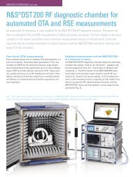
FIG 2 shows a typical system confi guration<br />
for mobile applications in the<br />
HF and VHF-UHF ranges. Antennas<br />
ADD190 and ADD071 are mounted<br />
on a telescopic mast attached to the<br />
vehicle. To minimize mutual interaction,<br />
HF Antenna ADD119 is set up on a<br />
tripod at a distance of about 40 m.<br />
ADD190 and ADD119 can be fi tted<br />
with an electronic compass (option) for<br />
automatic north alignment.<br />
To confi gure a system with only one<br />
mast – for example in stationary applications<br />
– with ADD190 mounted at the<br />
top of the mast, the disturbing effect of<br />
the mast in the HF range can be eliminated<br />
by using two Antennas ADD119<br />
on opposite sides of the mast in conjunction<br />
with Combiner GX119.<br />
Connection Board GX190 comprises<br />
a control-signal distributor plus an RF<br />
selector for 0.1 MHz to 3000 MHz,<br />
Compass<br />
GH150<br />
DF Antenna<br />
ADD 071<br />
(1300 MHz to<br />
3000 MHz)<br />
which connects one of maximally six<br />
antennas to the output. This is usually<br />
done by automatic control from DF Unit<br />
EBD190, but the system can also be<br />
confi gured for control via an RS-232-C<br />
interface.<br />
Special features<br />
DF Antenna ADD190 (20 MHz to 1300 MHz)<br />
RF<br />
IF<br />
HF DF Antenna ADD119<br />
Tripod<br />
AP502Z2<br />
Connection Board GX190<br />
Receiver<br />
Control<br />
TTL parallel<br />
DF Unit<br />
EBD190<br />
DF Unit EBD190 comes with a frontpanel<br />
keypad and LC display for convenient,<br />
straightforward operation. The<br />
receiver is operated separately; interfaces<br />
for antenna range selection are<br />
supported however. Sequential scanning<br />
of the antenna elements during<br />
Condensed data of DDF190<br />
Frequency range 0.5 MHz to 3000 MHz with three antennas<br />
and suitable receiver<br />
Polarization vertical<br />
DF accuracy 2° (rms) 0.5 MHz to 80 MHz<br />
1° (rms) 80 MHz to 1300 MHz<br />
2° (rms) 1.3 GHz to 3 GHz<br />
DF sensitivity (< 5° bearing fl uctuation<br />
(rms), 5 s integration time) 0.5 MHz to 30 MHz: 5 µV/m to 15 µV/m<br />
(frequency-dependent)<br />
20 MHz to 3000 MHz: 1 µV/m to 10 µV/m<br />
(frequency-dependent)<br />
Bandwidths HF: 0.25/0.5/1/3/5 kHz<br />
VHF/UHF: 1/2.5/8/25/100 kHz<br />
Reader service card 166/05<br />
Compass<br />
GH150<br />
RS-232-C<br />
FIG 2 Typical confi guration of mobile DF<br />
system for 0.5 MHz to 3000 MHz<br />
Articles<br />
the DF process leads to noise in the<br />
AF signal of the receiver typical of<br />
single-receiver direction fi nders. For<br />
undisturbed monitoring of the useful<br />
signal, the scanning function and thus<br />
direction fi nding can be switched off<br />
(AF/DF key).<br />
In most cases DF accuracy can be<br />
substantially improved, especially with<br />
noisy or disturbed signals, by choosing<br />
an appropriate averaging time<br />
(between 0.1 s and 5 s) and performing<br />
signal-matched fi ltering in DDF190<br />
(from 0.5 kHz to 100 kHz). Three<br />
operating modes (NORmal, CONTinuous,<br />
GATE) and several display modes<br />
(polar, numerical, histogram) are available<br />
for further optimization of direction<br />
fi nding for various types of application.<br />
A newly implemented Q (quality)<br />
fi lter effectively suppresses wild bearings.<br />
A realtime clock allows a time<br />
stamp to be output together with each<br />
bearing. This makes for easier allocation<br />
of information in networked DF<br />
and location systems.<br />
Franz Demmel; Ulrich Unselt<br />
REFERENCES<br />
[*] Demmel, Franz; Wille, Raimund: Digital<br />
direction fi nding from 20 to 3000 MHz to<br />
ITU guidelines. News from <strong>Rohde</strong> & <strong>Schwarz</strong><br />
(1996) No. 152, pp 30 – 32<br />
News from <strong>Rohde</strong> & <strong>Schwarz</strong> Number 166 (2000/I) 17
Articles<br />
Web over DTV<br />
Cost-attractive service through DVB:<br />
Transmission of extra data in Web format<br />
Web over DTV is a simple and cost-attractive solution for distributing Internet<br />
resources among TV viewers, for example, and for allowing TV providers to<br />
offer additional services with their programs. This service can be implemented by<br />
means of the <strong>Rohde</strong> & <strong>Schwarz</strong> DTV IP Inserter and DTV Web Carousel software.<br />
The underlying principle is to insert selected Internet data in IP format into the<br />
MPEG2 data stream of a DVB transmitter for broadcasting together with the TV<br />
signal via an antenna. The recipient can store this information in his PC and view<br />
it using a standard Web browser.<br />
DTV IP Inserter<br />
The DTV IP Inserter (FIG) allows transmission<br />
of additional data in Internet<br />
format (IP) with the DVB MPEG2 data<br />
stream. The DVB broadcaster can now<br />
offer an extra service to provide many<br />
viewers with the data. Transmission of<br />
these additional data is not subject to<br />
any restrictions and does not change the<br />
data rate of the programs contained in<br />
the transport stream, consisting of video,<br />
audio and service information. This is<br />
possible by utilizing unused resources<br />
(null packets) in the transport stream. A<br />
packet detector in DTV IP Inserter DIP<br />
identifi es the null packets inserted in the<br />
transport stream for stuffi ng, which are<br />
18 News from <strong>Rohde</strong> & <strong>Schwarz</strong> Number 166 (2000/I)<br />
then exchanged for IP packets and thus<br />
effectively utilized. Additional data can<br />
be inserted after the MPEG encoder or<br />
multiplexer by the multiprotocol encapsulation<br />
method defi ned for DVB.<br />
If the available transmission data rate<br />
is constant, the DTV IP Inserter directly<br />
follows the MPEG encoder (see block<br />
diagram) and the variable part of the<br />
video and audio data is supplemented<br />
with additional data to form a fi xed<br />
data rate. The clear advantage for<br />
program providers is the optimum utilization<br />
of the data rate. To make use of<br />
the resources available in the transport<br />
stream, the DTV IP Inserter is located<br />
after the multiplexer.<br />
DTV Web Carousel<br />
Convenient use of the resources provided<br />
by the DTV Inserter is ensured by<br />
the DTV Web Carousel system solution.<br />
This software allows to transmit<br />
selected Internet pages via DVB to<br />
stationary and mobile subscribers and<br />
to view these pages after reception<br />
with a common Web browser.<br />
Web Carousel sends the data without<br />
request, which exactly corresponds<br />
to the push principle used in teletext for<br />
example. The sense of transmission is<br />
unidirectional, communication is from<br />
transmitter to receiver.
Program 1<br />
Video<br />
Audio<br />
Data<br />
Program n<br />
Service info<br />
Video<br />
Audio<br />
Block diagram: use of free MPEG2 transport<br />
stream capacity with DTV IP Inserter DIP (see<br />
photo on right) in front of and after multiplexer<br />
DTV Web Carousel then sends the<br />
provided information pool cyclically to<br />
an addressed subscriber group. Once<br />
the end of the buffer is reached, transmission<br />
starts again from the beginning.<br />
The software receives the sent information<br />
as a list with Internet addresses<br />
(URLs) in the form of a text fi le. Switchover<br />
to new contents is possible irrespective<br />
of the current transmission.<br />
All applications with unidirectional<br />
transmission can be implemented with<br />
this system.<br />
Elke Schulze;<br />
Günther Zurek-Terhardt<br />
Reader service card 166/06<br />
MPEG<br />
video<br />
encoder<br />
MPEG<br />
audio<br />
encoder<br />
Inserter<br />
MPEG<br />
video<br />
encoder<br />
MPEG<br />
audio<br />
encoder<br />
Service<br />
MUX 1<br />
Service<br />
MUX n<br />
n Mbit<br />
MPEG2<br />
transport stream<br />
MPEG2<br />
transport stream<br />
IP data<br />
n Mbit<br />
DTV<br />
IP inserter<br />
DTV IP Inserter<br />
• Insertion of additional DVB-<br />
MPEG2 data in Internet format<br />
• Data transmission irrespective of<br />
DVB-C, DVB-T or DVB-S standard<br />
• Use of null packets that are not<br />
used in the transport stream<br />
• Exchange of data already contained<br />
in the transport stream<br />
• Insertion variants<br />
– Stuffi ng of remaining data rate<br />
– Dynamic stuffi ng to obtain fi xed<br />
data rate<br />
• Insertion of multicast applications<br />
• Insertion both in Intranet and<br />
Internet<br />
1<br />
2<br />
n<br />
Service<br />
Photo 43 451/3<br />
Transport<br />
MUX<br />
14.7 Mbit<br />
Web over DTV at a glance<br />
IP data<br />
DTV<br />
IP inserter<br />
Articles<br />
14.7 Mbit<br />
MPEG2<br />
transport stream<br />
DTV Web Carousel<br />
• Emission of any Internet contents<br />
• Convenient administration of<br />
contents to be sent<br />
• Contents can easily be compiled<br />
• Provision of data in IP format<br />
• Modular and scalable<br />
architecture<br />
• Secured unidirectional protocol<br />
for data transmission<br />
• Runs on standard PC with MS<br />
Windows NT<br />
News from <strong>Rohde</strong> & <strong>Schwarz</strong> Number 166 (2000/I) 19
Articles<br />
Content Management System eidonXbase<br />
Database-supported<br />
information management<br />
The technical documentation department of the service center at the<br />
<strong>Rohde</strong> & <strong>Schwarz</strong> Cologne plant offers allround solutions for the complete fi eld<br />
of modern publishing [*]. Cooperating with eidon GmbH, the Cologne specialists<br />
offer software products for information management. The eidonXbase Content<br />
Management System is of primary importance for documents in SGML, XML and<br />
CGM formats, plus comprehensive services to create system solutions for complex<br />
documentation and information tasks.<br />
More and more data<br />
The penetration of technology into daily<br />
life and increasing product complexity<br />
mean that a company’s documentation<br />
must observe a growing number of<br />
laws, standards and directives. It is<br />
not the piles of documents collected in<br />
a company that make for its success<br />
but mainly fast and proper access to<br />
the information required from case to<br />
case.<br />
A large part of information management<br />
is handled by the technical docu-<br />
20 News from <strong>Rohde</strong> & <strong>Schwarz</strong> Number 166 (2000/I)<br />
mentation department: complex processes<br />
and products have to be documented<br />
and the vast quantity of electronic<br />
documentation has to be managed<br />
and maintained.<br />
Throughput times must be reduced,<br />
all potential utilized and conditions<br />
created for optimizing documentation<br />
processes.<br />
With the right database, the effort<br />
involved in creating, managing and<br />
publicizing technical documentation<br />
can be reduced and the increasing<br />
FIG 1<br />
Fast access even to<br />
extremely comprehensive<br />
documents<br />
with eidonXbase<br />
Content Management<br />
System<br />
amount of data dealt with more effi -<br />
ciently. Stored information can be<br />
multiply re-used and generation costs<br />
reduced. eidonXbase is a powerful<br />
tool for information management of<br />
this kind.<br />
Databases for a better grasp<br />
The eidonXbase Content Management<br />
System supports joint documentation<br />
editing and ensures fast companywide<br />
access to information. The systems<br />
integrated in the software map<br />
Glossary<br />
CGM Computer Graphics Metafi le;<br />
graphical fi le format<br />
DTD Document Type Defi nition<br />
JDBC/<br />
ODBC Open DataBase Connectivity;<br />
interface allowing integration<br />
of data from any applications<br />
into a database<br />
Oracle8i Database from Oracle<br />
SGML Standard Generalized Markup<br />
Language; programming<br />
language for technical documentation<br />
SQL Structured Query Language<br />
XML Extensible Markup Language<br />
(part of SGML)
FIG 2 Convenient translation management for<br />
multilingual documentation<br />
workfl ows and help technical writers<br />
coordinate wide-ranging projects in<br />
many languages. This system, especially<br />
designed to manage documentation<br />
on the Internet, offers many advantages<br />
and possibilities of application<br />
through extremely fast access to any<br />
documentation and its parts (FIG 1).<br />
eidonXbase is extremely easy to handle<br />
despite high functionality and automation<br />
potential. Familiarization time is<br />
very short, adaptation to changing<br />
requirements is very easy and can be<br />
done by the user. The simply confi gured,<br />
graphical user interface allows<br />
user-specifi c views of the managed<br />
documents.<br />
The degree of automation of steering<br />
and production processes in technical<br />
documentation can be intensifi ed by<br />
the integrated Xript script language.<br />
Architecture<br />
eidonXbase stores and manages XML<br />
and SGML texts as well as CGM4<br />
graphics in the form of single data<br />
sets in a relational SQL database and<br />
thus allows extremely fast and precise<br />
access. The database also manages<br />
the contents of other documents but<br />
stores them in a special area of the<br />
fi le system. It is addressed through<br />
JDBC/ODBC. The software is implemented<br />
entirely as a Java application in<br />
a modern three-layer architecture and<br />
thus also fully Internet-compatible.<br />
The content management system is<br />
standard-conformant throughout and<br />
can be used on virtually all platforms<br />
(hardware, operating system, SQL database).<br />
It makes optimum use of relational<br />
database characteristics, so it is<br />
very fast and highly scalable. Integration<br />
into corporate data processing is<br />
simplifi ed enormously by setting up on<br />
tried and tested SQL technology. Operating<br />
eidonXbase on Oracle8i, for<br />
example, allows homogeneous implementation<br />
of document- and data-oriented<br />
XML applications.<br />
Heinz-Peter Olbrück<br />
REFERENCES<br />
[*] Zorenböhmer, Jörg: Database-supported<br />
documentation – Technical documentation<br />
by high-tech methods. News from<br />
<strong>Rohde</strong> & <strong>Schwarz</strong> (1999) No. 162,<br />
pp 16–17<br />
Reader service card 166/07<br />
Articles<br />
Functions<br />
• Data memory in relational SQL<br />
database<br />
• Powerful script language, programming<br />
interface (Java-API),<br />
SQL access<br />
• User and group management<br />
• Re-use of document contents<br />
• Translation management (FIG 2)<br />
Functions for documents<br />
• Check in/out with version<br />
numbering<br />
• Document families (topics)<br />
• Trigger functions (import, export,<br />
delete)<br />
• Access to documents and<br />
versions<br />
• Protection against unauthorized<br />
or competitive access<br />
Additional functions for subordinate<br />
documents<br />
• Full support of XML, SGML and<br />
CGM4 formats<br />
• Meta data<br />
• Access to any subordinate documents,<br />
part versions, attributes,<br />
entities, etc<br />
• Import with/without DTD<br />
checking<br />
• Entities and DTD management<br />
News from <strong>Rohde</strong> & <strong>Schwarz</strong> Number 166 (2000/I) 21
Application notes<br />
I/Q Modulation Generator AMIQ<br />
New models 03 and 04 as well as<br />
digital I/Q output option<br />
Since its successful market launch two years ago, I/Q Modulation Generator<br />
AMIQ [1] has undergone intensive upgrading, which considerably increased<br />
its versatility [2]. Together with the WinIQSIM software [3], the previous model<br />
enabled generation of a huge number of waveforms covering a wide range of<br />
applications. The new models AMIQ03 and 04 (FIG 1) once again substantially<br />
widen the spectrum of applications.<br />
FIG 1 New AMIQ04 model with differential<br />
I/Q outputs and digital I/Q output options<br />
New features in brief<br />
• Digital I/Q Output option<br />
AMIQ-B3: This option adds the<br />
associated digital control signals<br />
to the analog outputs. The new<br />
Example: bit-error-rate measurements<br />
on TDMA systems<br />
Bit-error-rate measurements are normally<br />
performed using a pseudo-random binary<br />
sequence (PRBS). For a realistic test scenario,<br />
the PRBS to be evaluated must be<br />
continuously embedded in the TDMA data<br />
structure. Also, the PRBS should not be interrupted<br />
to guarantee smooth operation of<br />
the BER tester. This requires test signals with<br />
long data sequences. If a PRBS 9 sequence<br />
is used, 511 TDMA frames usually have to<br />
be generated (2 9 –1). Its storage capacity<br />
of 16 Msamples makes AMIQ04 ideal for<br />
this kind of application. FIG 2 shows a typical<br />
test setup with AMIQ and the optional<br />
22 News from <strong>Rohde</strong> & <strong>Schwarz</strong> Number 166 (2000/I)<br />
models 03 and 04 come ready<br />
for integration of the digital I/Q<br />
output option.<br />
• Models 03 and 04 may also work<br />
with an external clock via their<br />
CLK connector. This allows generators<br />
to be synchronized to a central<br />
system clock and avoid interference<br />
due to clock beats.<br />
BER Measurement AMIQ-B1. AMIQ is<br />
also an excellent source of multicarrier<br />
signals, so signals in adjacent channels or<br />
other interference signals can be generated<br />
in addition to the<br />
useful carrier with-<br />
out the need for a<br />
second generator.<br />
This allows typical<br />
receiver tests like<br />
adjacent-channel<br />
rejection or blocking.<br />
SMIQ<br />
Photo 43 419/2<br />
Win<br />
IQSIM<br />
IEC/<br />
IEEE bus<br />
• The resolution of output signals<br />
can be selected between 8 and<br />
16 bits. So DACs (digital/analog<br />
converters) with different bit<br />
widths, for example, can be used<br />
with the digital I/Q output option.<br />
• Model 04 has even larger storage<br />
capacity, enabling it to store and<br />
output complex curves of up to<br />
16 Msamples.<br />
Digital I/Q output option<br />
There is a marked trend towards digital<br />
signal processing. AMIQ’s answer to<br />
this development is the new option<br />
AMIQ-B3, which makes digital control<br />
signals available together with the<br />
associated clock signals and offers<br />
highly convenient operation through<br />
WinIQSIM.<br />
FIG 2 Measurement of bit error rate<br />
RF<br />
AMIQ<br />
Bit clock, control signals<br />
or<br />
Marker<br />
I/Q<br />
BERT<br />
DUT<br />
Data<br />
bits
This new option can supply a connected<br />
DUT with a voltage of +3.3 V or<br />
+5 V. The high levels of data and clock<br />
adjust automatically. A special feature<br />
of the digital output is that it outputs<br />
data and clock only for DUTs with<br />
the supply voltage applied. Otherwise<br />
all outputs are of high impedance to<br />
protect sensitive circuitry of the DUT.<br />
To avoid refl ection when operating<br />
AMIQ with clock frequencies >40 MHz,<br />
it is advisable to connect DUTs to the<br />
output using very short lines or to terminate<br />
them with the required impedance.<br />
A host of new applications<br />
The digital output allows a wide selection<br />
of applications. These range from<br />
measurements on DACs through tests<br />
of digital mobile-radio interfaces (see<br />
examples in boxes) to the use of lowvoltage<br />
differential signalling (LVDS)<br />
links. With the latter, high-frequency<br />
digital links (several hundred MHz)<br />
can be made on long lines using differential<br />
signals of low amplitude. For<br />
this purpose AMIQ-B3 drives an LVDS<br />
transmitter component that converts<br />
the signals into a serial data stream of<br />
higher frequency. A cable up to 10 m<br />
long connects the transmitter output<br />
with an LVDS receiver, which converts<br />
the data back into their original parallel<br />
format. In this way the digital signals<br />
from AMIQ-B3 can be routed over long<br />
distances or the associated LVDS chips<br />
can be tested.<br />
Through continuous product upgrading<br />
and especially thanks to the new<br />
AMIQ-B3 option, AMIQ once more<br />
emphasizes its role as a universal modulation<br />
generator meeting all requirements<br />
of the digital communication<br />
age.<br />
Burkhard Küfner;<br />
Dr Rene Desquiotz<br />
Example: testing DACs<br />
Digital/analog converters<br />
(DACs) link the<br />
digital to the analog<br />
world. High-resolution<br />
digital words at<br />
high sample frequency<br />
are needed<br />
to test new DAC<br />
designs. Its optional<br />
digital I/Q output<br />
makes AMIQ03/04<br />
ideal for this application<br />
due to word<br />
width of up to 16 bits<br />
per channel and a<br />
clock frequency up to<br />
100 MHz (FIG 3).<br />
CLK<br />
ext.<br />
Internal<br />
clock<br />
source<br />
REFERENCES<br />
[1] Kernchen, Wolfgang; Tiepermann, Klaus-<br />
Dieter: I/Q Modulation Generator AMIQ –<br />
Convenient generation of complex I/Q signals.<br />
News from <strong>Rohde</strong> & <strong>Schwarz</strong> (1998)<br />
No. 159, pp 10 –12<br />
[2] Küfner, Burkhard: I/Q Modulation Generator<br />
AMIQ – more applications through dif-<br />
Condensed data of AMIQ-B3<br />
Output 68-pin connector (submin D, half pitch)<br />
Number of channels 2 (one each for I and Q)<br />
Resolution selectable from 8 to 16 bits<br />
Output impedance approx. 50 Ω (typ.)<br />
DC voltage output selectable +3.3 V or +5 V<br />
Clock frequency max. 100 MHz (normal and inverted<br />
polarity)<br />
Reader service card 166/08<br />
int.<br />
I signal<br />
A critical aspect of<br />
these measurements<br />
is the spectral purity of the clock used. An<br />
impure clock signal causes a DAC to generate<br />
additional harmonics and nonharmonics,<br />
which in turn reduce the spurious-free<br />
dynamic range. To eliminate this source<br />
of error, the DUT can be supplied with a<br />
clock of extremely high spectral purity from<br />
an external source, eg a crystal oscillator<br />
or synthesizer, and the matching control<br />
signals obtained from the digital AMIQ<br />
output. AMIQ is driven by the same clock<br />
for the necessary synchronization of clock<br />
edges with the data from the option. For<br />
clock frequencies above approx. 40 MHz,<br />
CLK<br />
I signal<br />
Q signal<br />
Latch<br />
DAC<br />
DAC<br />
≤16<br />
CLK<br />
VCC<br />
Q signal Latch<br />
≤16<br />
AMIQ AMIQ-B3<br />
DUT<br />
Application notes<br />
Delay<br />
External<br />
clock<br />
source<br />
DAC<br />
DAC<br />
FIG 3 AMIQ with AMIQ-B3 option testing<br />
DACs<br />
the internal delay of AMIQ (max. approx.<br />
25 ns) has to be taken into account by<br />
delaying the clock accordingly.<br />
After loading of the desired trace into the<br />
AMIQ output memory by WinIQSIM (sinusoidal<br />
or multitone signal), a spectrum<br />
analyzer can be used to check the impact<br />
on spectral purity at the DUT output by<br />
varying bit width and clock frequency.<br />
ferential I/Q outputs. News from <strong>Rohde</strong> &<br />
<strong>Schwarz</strong> (1999) No. 162, pp 20 –21<br />
[3] Pauly, Andreas; Holzhammer, Jens: I/Q<br />
Simulation Software WinIQSIM – New<br />
approaches in calculating complex I/Q signals.<br />
News from <strong>Rohde</strong> & <strong>Schwarz</strong> (1998)<br />
No. 159, pp 13–15<br />
News from <strong>Rohde</strong> & <strong>Schwarz</strong> Number 166 (2000/I) 23
Application notes<br />
Microwave Signal Generator SMR<br />
SMR as tracking generator for<br />
Vector Network Analyzer ZVM<br />
The four models of the SMR family of signal sources cover the frequency range<br />
up to 20 GHz (SMR20), 27 GHz (SMR27), 30 GHz (SMR30) and 40 GHz (SMR40,<br />
FIG 1). All have a lower limit frequency of 1 GHz, which can optionally be<br />
extended down to 10 MHz. The immediate advantages of SMR are small size,<br />
light weight, high performance and an extremely attractive price [1]. The brandnew<br />
Vector Network Analyzer ZVM extends the frequency range of the successful<br />
ZVR analyzer family up to 20 GHz. The two units together – SMR and ZVM – are<br />
an ideal combination to make complex RF measurements child’s play.<br />
FIG 1 Microwave Signal Generator SMR40: a<br />
sought-after signal source in research, development,<br />
production and EMC measurements<br />
The ZVR family [2] already includes<br />
units for 9 kHz to 4 GHz (ZVR, ZVRE,<br />
ZVRL) and 20 kHz to 8 GHz (ZVC,<br />
ZVCE) and with the new member now<br />
also 10 MHz to 20 GHz. Like all vector<br />
network analyzers of the family, ZVM<br />
too has outstanding features (see box<br />
and FIG 2).<br />
But why does such a versatile and<br />
sophisticated network analyzer like<br />
ZVM need one or even two external<br />
generators? After all, it is already fi tted<br />
with a microwave source whose characteristics<br />
meet any requirements. The<br />
answer can be found in FIG 3, where<br />
a frequency-converting DUT is shown<br />
with a receive section for 200 MHz to<br />
7 GHz and an output at the fi xed IF of<br />
24 News from <strong>Rohde</strong> & <strong>Schwarz</strong> Number 166 (2000/I)<br />
741 MHz. The test setup allows measurement<br />
of mixer gain as a function of<br />
receive frequency, for instance, which<br />
is a standard measurement on receive<br />
units. The following frequency settings<br />
have to be made for the purpose (all RF<br />
levels have to be selected so that the<br />
DUT operates correctly of course):<br />
• Set SMR at mixer 2 to fi xed frequency<br />
of 3.6 GHz.<br />
• Set receive section of ZVM to test<br />
frequency of 741 MHz.<br />
• Set generator of ZVM to frequency<br />
sweep from 200 MHz to 7 GHz.<br />
• Set SMR at mixer 1 to frequency<br />
sweep from 8.141 GHz to<br />
14.941 GHz.<br />
All these settings are performed via the<br />
convenient user interface of the vector<br />
network analyzer. This also applies to<br />
the generator settings, remotely controlled<br />
by ZVM via the IEC/IEEE-bus connection.<br />
Photo 43 264/3<br />
For a measurement to run properly, the<br />
ZVM generator and SMR have to be<br />
synchronously tuned at mixer 1. In the<br />
example this is done with a frequency<br />
offset of 7.941 GHz, corresponding<br />
to the fi rst IF of the receive section. In<br />
the simplest case, ZVM sets SMR to<br />
the required frequencies at mixer 1<br />
via the IEC/IEEE bus. But this method<br />
is too slow, especially if DUT alignments<br />
are to be made. Luckily things<br />
can be done much faster, the network<br />
analyzer only has to be fi tted with<br />
option ZVR-B4, and terminals TRIG-<br />
GER and BLANK on ZVM and SMR<br />
have to be linked with the appropriate<br />
cable. Using this special interface, SMR<br />
becomes a real tracking generator for<br />
ZVM, or any other network analyzer<br />
of the ZVR family, since the generator’s<br />
maximum tuning speed of approx.<br />
1 GHz/ms now comes into play. That is<br />
more than enough for all conceivable<br />
adjustments of common DUTs.<br />
So where does this big boost in speed<br />
come from? You need look no further<br />
than the List mode provided in every<br />
SMR. For this mode, you fi rst create<br />
a list with frequencies and the associated<br />
levels. SMR can subsequently step<br />
through this list, in the auto mode or<br />
externally triggered. If there are ascending<br />
frequencies for constant level, a<br />
digital step sweep of crystal accuracy<br />
is performed, which can be accomplished<br />
extremely fast. Up to ten lists<br />
can be created in SMR, either manually<br />
or via the IEC/IEEE bus. So a<br />
maximum of 2003 frequency points
can be stored (up to 2001 of them<br />
being used by ZVM to resolve the frequency<br />
axis). With SMR used as a<br />
tracking generator, ZVM automatically<br />
generates the required list and loads it<br />
in SMR via the IEC/IEEE bus – it is all<br />
done for you. ZVM then activates the<br />
List mode of SMR via the IEC/IEEE bus<br />
with the external trigger and sends a<br />
trigger pulse to SMR. Every time SMR<br />
fi nishes a frequency step, it acknowledges<br />
by resetting the BLANK signal,<br />
and then ZVM triggers again. This<br />
method also works with the microwave<br />
signal generators of the SMP family<br />
and the RF sources SME and SMIQ.<br />
Wilhelm Kraemer<br />
REFERENCES<br />
[1] Kraemer, Wilhelm: Microwave Signal<br />
Generator SMR: Microwave in handy<br />
size. News from <strong>Rohde</strong> & <strong>Schwarz</strong> (1999)<br />
No. 162, pp 4–6<br />
[2] Ostwald, Olaf; Evers, Christian: Vector Network<br />
Analyzer ZVC: Double frequency and<br />
benefi t. News from <strong>Rohde</strong> (1998) No. 158,<br />
pp 4–6<br />
– Application Note 1EZ31_0E: Measurements<br />
on Frequency-Converting DUTs using<br />
Vector Network Analyzer ZVR<br />
Reader service card 166/09<br />
Trigger<br />
Blank<br />
200 MHz to 7 GHz<br />
SMR<br />
Port 1<br />
8.141 GHz to<br />
14.941 GHz<br />
ZVM<br />
Port 2<br />
SMR<br />
FIG 2<br />
New Vector Network<br />
Analyzer ZVM<br />
in one of its special<br />
applications: patented<br />
calibration<br />
methods from<br />
<strong>Rohde</strong> & <strong>Schwarz</strong><br />
allow easy and<br />
highly precise measurements<br />
on wafers<br />
IEC2<br />
Mixer 1 Mixer 2<br />
DUT<br />
(frequency-converting)<br />
RF RF<br />
IEC/IEEE bus<br />
741 MHz<br />
2f<br />
f<br />
3.6 GHz<br />
FIG 3<br />
Measurement of<br />
double frequencyconverting<br />
receiver<br />
front-end<br />
Application notes<br />
The new Vector Network<br />
Analyzer ZVM<br />
• Frequency range<br />
10 MHz to 20 GHz<br />
• Excellent dynamic range >115 dB<br />
(IF bandwidth 10 Hz)<br />
• High measurement speed<br />
Application notes<br />
Calculating measurement uncertainty<br />
of conformance test systems for mobile phones<br />
Conformance tests on mobile phones call for utmost RF accuracy. ETSI test specifi cation<br />
ETR028 [1], for example, deals with the subject of “uncertainties in the measurement<br />
of mobile-radio equipment”. In conformance test systems a reasonable<br />
compromise has to be found between measurement uncertainty, costs, automation<br />
and test time. This article shows, by way of example, how measurement uncertainties<br />
in conformance test systems from <strong>Rohde</strong> & <strong>Schwarz</strong> can be determined.<br />
Measurement tasks<br />
Conformance tests on mobile phones<br />
not only comprise protocol and audio<br />
tests but, very importantly, also measurement<br />
of RF parameters for compliance<br />
with specifi cations. The RF<br />
parameters are measured in the frequency<br />
band of the particular mobileradio<br />
standard (inband) as well as<br />
outside this range between 9 kHz and<br />
12.75 GHz (wideband); the applicable<br />
test methods are defi ned by ETR027<br />
[2]. System-specifi c test methods are<br />
described in the specifi cations for<br />
the individual mobile-radio standards,<br />
for example in ETS300607 (GSM<br />
11.10) for GSM900/GSM1800, or<br />
in ETS300394 for TETRA.<br />
The measurement uncertainties involved<br />
in laboratory test setups and in test<br />
systems are essentially attributable<br />
to the following factors (see also [3]<br />
and [4]):<br />
• frequency response of instruments/<br />
cabling,<br />
• linearity error of instrument levels,<br />
• mismatch resulting from interconnection<br />
of instruments, cables and<br />
EUT.<br />
Computation standards<br />
ETR028 is applicable in Europe for<br />
determining measurement uncertainties<br />
in conformance testing. The offi -<br />
cial version dates back to 1994 and<br />
comprises about 128 pages. In 1997<br />
a draft follow-up version appeared<br />
in two volumes with a total of about<br />
420 pages. The later version appears<br />
26 News from <strong>Rohde</strong> & <strong>Schwarz</strong> Number 166 (2000/I)<br />
to have been considerably improved<br />
in many aspects, so the examples<br />
given below are based on this version<br />
although it is not yet offi cially in<br />
force.<br />
Strategies in dealing with<br />
measurement uncertainties<br />
Advantages and disadvantages of<br />
switching matrix<br />
All instruments in a test system are<br />
connected to the EUT via a switching<br />
matrix (signal switching and conditioning<br />
unit – SSCU). Measurement uncertainties<br />
caused by mismatch are greater<br />
than in a manual test setup unless special<br />
precautions are taken. But the<br />
major advantage of this method is that<br />
the EUT needs to be connected only<br />
once and the various test setups can<br />
be created by means of relays. This<br />
method does away with manual intervention<br />
during the test, saves considerable<br />
time and avoids operator errors.<br />
Plus, it is possible to compensate the<br />
frequency response of instruments and<br />
cabling as well as linearity errors of<br />
the instruments in a test system – this<br />
method is employed, for example, in<br />
the path compensation software of<br />
<strong>Rohde</strong> & <strong>Schwarz</strong> conformance test systems.<br />
Calibration with power meter<br />
The frequency response and linearity<br />
error of the remaining instruments and<br />
the test setup can in addition be calibrated<br />
using a power meter with<br />
measurement uncertainty traceable to<br />
national standards. For this purpose<br />
the power meter, acting as a reference,<br />
is connected via relays to suitable test<br />
points in the SSCU. Without this calibration<br />
the linearity error and frequency<br />
response of the signal generators used<br />
is approx. 1.5 dB. Calibration of the<br />
complete system reduces measurement<br />
uncertainty to below 1 dB (at 95 % confi<br />
dence level).<br />
Calibration of RF generators<br />
As a rule, a signal with a known, fi xed<br />
level and variable frequency is applied<br />
to the EUT in the test cases. For this,<br />
the generators have to be calibrated to<br />
the nominal levels required for the test<br />
cases in question to signifi cantly reduce<br />
the effects of generator linearity and<br />
frequency error. To save the operator<br />
from having to screw the power sensors<br />
to the cable to the EUT prior to<br />
each test run, the difference between<br />
an internal test point and the end of<br />
the EUT cable is fi rst measured as a<br />
function of frequency and stored. The<br />
resulting trace is independent of level<br />
and constant over an extended period<br />
of time. It is used to calibrate generators<br />
at different levels, which can be<br />
performed fully automatically and thus<br />
immediately before the actual test, thus<br />
avoiding errors caused by generator<br />
temperature drift. Neglecting uncertainties<br />
due to mismatch, the absolute error<br />
of 1.5 dB can be reduced to the repeat<br />
accuracy (approx. 0.1 dB) and the<br />
measurement inaccuracy of the power<br />
meter. Depending on frequency and<br />
level, this is only about 0.1 dB in the<br />
case of <strong>Rohde</strong> & <strong>Schwarz</strong>’s NRVD with<br />
its Sensor -Z1.
Calculation of measurement<br />
uncertainty<br />
Calculation example 1<br />
All the above measurements involve<br />
uncertainties due to mismatch however.<br />
In ETR028, calculation of these uncertainties<br />
is discussed and demonstrated<br />
by many examples. The refl ections of<br />
all RF components involved are added<br />
up according to statistical laws. If a<br />
large number of components are used,<br />
this leads to unnecessarily great measurement<br />
uncertainties.<br />
This is demonstrated by an example<br />
based on the computation standard<br />
for measurement of an EUT that is<br />
connected to a spectrum analyzer<br />
(“specan” in the formula) via an SSCU<br />
(FIG 1) containing relays (K1 to K7)<br />
and a 10 dB attenuator (R1). The calculation<br />
of measurement uncertainties<br />
resulting from path refl ections is shown<br />
in TABLE 1, where<br />
Order Refl ections between two neighbouring<br />
components are called<br />
1st-order refl ections, refl ections<br />
between two components with<br />
one other component between<br />
them are called 2nd-order refl ections,<br />
etc<br />
ui Standard measurement uncertainty<br />
due to ith-order refl ections<br />
(see TABLE 1)<br />
re Refl ection coeffi cient of<br />
component e<br />
ae Transmission coeffi cient<br />
of component e<br />
EUT Equipment under test<br />
Result<br />
The total standard measurement uncertainty<br />
due to mismatch is approx.<br />
0.56 dB (standard uncertainty 1 σ) in<br />
this example. To obtain a confi dence<br />
level of 95 %, this value has to be multiplied<br />
by 1.96, which results in an<br />
expanded uncertainty of approx. 1.1 dB.<br />
The data of the components involved<br />
are taken from their data sheets.<br />
Spectrum analyzer<br />
C7 C6<br />
SSCU<br />
FIG 1 Part of SSCU used in <strong>Rohde</strong> & <strong>Schwarz</strong> conformance test systems<br />
FIG 2<br />
Measured refl ection<br />
and transmission of<br />
SSCU<br />
y/dB<br />
0<br />
–10<br />
–20<br />
–30<br />
–40<br />
–50<br />
R1<br />
C5 C4 C3 C2<br />
C1<br />
Transmission<br />
Reflection<br />
–60<br />
1 1.5 2 2.5 3 3.5<br />
f/GHz<br />
4<br />
TABLE 1 Calculation of measurement uncertainty due to path refl ections<br />
Calculation example 1 Result<br />
Reflections between neighbouring components (1st-order reflections)<br />
C<br />
C<br />
2nd-order reflections<br />
C<br />
C<br />
C<br />
C<br />
C<br />
C<br />
C C<br />
C<br />
9th-order reflections<br />
Total standard measurement uncertainty<br />
C<br />
C C<br />
C C C<br />
Application notes<br />
0.39 dB<br />
0.039 dB<br />
0.11 dB<br />
0.27 dB<br />
0.00 dB<br />
0.1 dB<br />
0.039 dB<br />
0.56 dB<br />
News from <strong>Rohde</strong> & <strong>Schwarz</strong> Number 166 (2000/I) 27<br />
DST
Application notes<br />
Calculation example 2<br />
According to [1], the scattering matrix<br />
of the SSCU can alternatively be measured<br />
by means of a network analyzer,<br />
the SSCU being treated as a complex<br />
component. In the example below,<br />
this yields a transmission coeffi cient of<br />
approx. 13 dB and a refl ection coeffi<br />
cient of r = 0.04. FIG 2 shows the<br />
frequency response of the transmission<br />
coeffi cient and of the refl ection coeffi<br />
cient at the input end.<br />
Calculation is thus reduced to a<br />
few steps (TABLE 2). The total standard<br />
measurement uncertainty is only<br />
0.18 dB, which corresponds to an<br />
expanded measurement uncertainty of<br />
0.36 dB (confi dence level 95 %).<br />
Summary<br />
Even with this simple example, the<br />
results obtained with the two computation<br />
models differ by more than 0.7 dB<br />
at 95 % confi dence level. The values<br />
obtained for example 1, taking into<br />
account all SSCU components involved, Reader service card 166/10<br />
CD-ROM<br />
The endless universe, mobile phones<br />
fl ying through space. These are the<br />
visionary images that greet the viewer<br />
of the CD-ROM presentation for Universal<br />
Radio Communication Tester CMU.<br />
After the introduction come the details:<br />
a transparent, intuitive user interface<br />
invites the viewer to go on a discovery<br />
trip of CMU. And there is plenty to<br />
explore. Just one click and an animated<br />
CMU offers an overview of the<br />
characteristics and design of the tester<br />
as well as potential applications. This<br />
part of the presentation describes operation,<br />
available measurements and<br />
optional device confi gurations. The<br />
user can rapidly create his very own<br />
CMU with all the available options<br />
28 News from <strong>Rohde</strong> & <strong>Schwarz</strong> Number 166 (2000/I)<br />
Calculation example 2 Result<br />
Total standard measurement uncertainty<br />
TABLE 2 Calculation example with SSCU treated as complex component<br />
are apparently too high. However, by<br />
measuring the test setup with a network<br />
analyzer and treating the SSCU as<br />
a complex component in accordance<br />
with [1], the measurement uncertainty<br />
stipulated by specifi cations can still be<br />
guaranteed for the same wiring.<br />
Michael Manert<br />
Exploring the world of mobile-radio tester CMU<br />
using a convenient tool. Confi gurations<br />
can easily be exported for consultation<br />
with colleagues or a<br />
<strong>Rohde</strong> & <strong>Schwarz</strong> sales<br />
engineer for example.<br />
The CD-ROM<br />
contains the complete<br />
data sheet<br />
for those needing<br />
more in-depth<br />
information on the<br />
tester. The opening<br />
page contains not only<br />
CMU data and features<br />
but also general information on<br />
<strong>Rohde</strong> & <strong>Schwarz</strong>, CMU training<br />
0.17 dB<br />
0.49 dB<br />
0.04 dB<br />
0.18 dB<br />
REFERENCES<br />
[1] ETR 028, ETSI Technical Report, 3rd Edition,<br />
June 1997 (unpublished work), “Uncertainties<br />
in the measurement of mobile radio<br />
equipment characteristics”, parts 1 and 2<br />
[2] ETR 027, ETSI Technical Report, 3rd Edition,<br />
June 1997 (unpublished work), “Methods<br />
of measurement for private mobile radio<br />
equipment”<br />
[3] Minihold, Roland: RF Level Test System.<br />
<strong>Rohde</strong> & <strong>Schwarz</strong> Application Note 1999,<br />
1MA21-1E<br />
[4] Wolf, Josef: Level Error Calculation for Spectrum<br />
Analyzers. <strong>Rohde</strong> & <strong>Schwarz</strong> Application<br />
Note 1998, 1EF 036-0E<br />
courses plus a list of worldwide sales<br />
offi ces with addresses and contacts.<br />
All in all this CD-ROM<br />
offers a highly practical<br />
approach for<br />
getting to know<br />
CMU and provides<br />
a good initial<br />
impression<br />
of the enormous<br />
performance and<br />
versatility of Universal<br />
Radio Communication<br />
Tester CMU.<br />
Stefan Böttinger
Photo 43 210/2<br />
Photo 43 125/2<br />
Coverage Measurement Software ROMES 3<br />
Acquisition, analysis and visualization<br />
of data in coverage measurements<br />
Communication with seamless coverage and without interference, reliable data<br />
transmission at an acceptable speed – these and many other quality criteria<br />
are decisive for the success of a mobile-radio network on the market. To enable<br />
network operators to provide the required quality – and thus be commercially<br />
successful – <strong>Rohde</strong> & <strong>Schwarz</strong> offers with its TS995x product line (FIG 1) hardware<br />
and software for all standards available today. Common to all systems is the<br />
modular and versatile Measurement Software ROMES 3.<br />
Complete solutions for<br />
communication networks<br />
Coverage measurement systems from<br />
<strong>Rohde</strong> & <strong>Schwarz</strong> accommodate virtually<br />
all fi elds of application: from network<br />
planning, installation and optimization<br />
through to network servicing<br />
and monitoring. Measured-data<br />
acquisition, test signal generation and<br />
result analysis are carried out comprehensively,<br />
fast and with high precision.<br />
The new Measurement Software<br />
ROMES 3 provides the platform for<br />
all these systems, which allow most<br />
network problems to be detected and<br />
analyzed. ROMES 3 collects data fast<br />
and conveniently during test tours and<br />
offers versatile visualization to meet<br />
user’s requirements.<br />
Universal and future-proof<br />
Modular concept<br />
ROMES 3 is based on a modular<br />
system concept, allowing any type of<br />
data to be collected and analyzed<br />
(FIG 2). Any sensor (eg test receiver,<br />
test mobile or GPS receiver) capable<br />
of result transfer to a PC can be used.<br />
This opens up a wide range of use,<br />
FIG 1<br />
TS995x offers an extensive<br />
line of products for<br />
mobile-radio networks<br />
covering practically all<br />
fi elds of application: network<br />
planning, installation,<br />
optimization and<br />
monitoring. The example<br />
below shows portable<br />
system TS9951 (case)<br />
and high-performance<br />
test system TS9955<br />
(vehicle).<br />
Photo 43 125/1<br />
Software<br />
News from <strong>Rohde</strong> & <strong>Schwarz</strong> Number 166 (2000/I) 29
Software<br />
Hardware Software<br />
RS-232-C<br />
IEEE<br />
USB<br />
EtherNet<br />
PCI<br />
ISA<br />
Driver<br />
Driver<br />
ASCII<br />
Dependent on device<br />
Independent of devices and technology<br />
Dependent on technology<br />
User-configurable<br />
Export Export<br />
Result files<br />
Core<br />
from measurements in mobile-radio<br />
and DAB/DVB networks through to<br />
almost any kind of exotic application.<br />
The modular concept enables the implementation<br />
of very small systems and<br />
high-performance test systems alike.<br />
And it makes the software future-proof,<br />
as it can easily be extended to accommodate<br />
upcoming technologies (eg<br />
W-CDMA).<br />
The core of the application can handle<br />
any kind of data and routes the incoming<br />
data stream to the appropriate<br />
software modules. All signals detected<br />
are stored on hard disk immediately on<br />
arrival at the core and visualized in a<br />
form meeting the user’s requirements.<br />
Apart from the core, there are numerous<br />
modules by which software can<br />
be extended to suit a given application.<br />
The modules are all available as<br />
options, so custom solutions can be<br />
confi gured fast. For example, different<br />
transmission technologies can be<br />
combined and/or multiply provided in<br />
a measurement system (eg a CDMA,<br />
two GSM and an ETACS mobile, a<br />
test receiver and GPS).<br />
30 News from <strong>Rohde</strong> & <strong>Schwarz</strong> Number 166 (2000/I)<br />
ROMES 3<br />
data format<br />
Technology<br />
X<br />
Alphanumeric values<br />
General<br />
GSS<br />
Special<br />
GSS<br />
Technology<br />
Y<br />
2D<br />
chart<br />
Map<br />
view<br />
Meas.<br />
report<br />
Layer<br />
3<br />
GSS: graphical subsystem<br />
FIG 2 The modular concept of ROMES 3 allows<br />
both very small systems and complex high-performance<br />
test systems to be implemented<br />
Integrated database<br />
ROMES 3 has an integrated database<br />
that allows customer-specifi c data to be<br />
included in result analysis. Results can<br />
be automatically linked to database<br />
contents, for example to a list of all<br />
base stations, from which the software<br />
then extracts the stations used.<br />
Simple, intuitive user interface<br />
The core of ROMES 3 also comprises<br />
the major part of the user interface,<br />
which offers many special features:<br />
• Central confi guration of all signals,<br />
events and modules known in the<br />
system<br />
• Automatic loading of working environments<br />
last stored upon restart<br />
of the application<br />
• Online confi guration of views via<br />
context menus, so display parameters<br />
can be added or removed<br />
during measurement<br />
• Multiview technique<br />
• User-confi gurable shortcuts<br />
• Context-sensitive online help etc<br />
Pipes between modules enable new<br />
applications<br />
ROMES 3 provides a simple yet effi -<br />
cient interface allowing communication<br />
between different modules<br />
via pipes (pipes are communication<br />
links between independent software<br />
modules). This is a precondition for<br />
master/slave operation, where one<br />
module drives another. The pipe concept<br />
opens up versatile applications,<br />
for example simultaneous testing of<br />
data or fax transmissions (see box) or<br />
recording of data measured with the<br />
test mobile.<br />
Analysis tools of ROMES 3<br />
Apart from effi cient measured-data<br />
acquisition, ROMES 3 offers comprehensive<br />
functionality for the localization<br />
of problems so that solutions can<br />
be found quickly.<br />
Search functions<br />
Replay, a powerful analysis and search<br />
function, is an integral part of the measurement<br />
software permitting fast and<br />
effi cient analysis without extra software<br />
tools. Replay reproduces recorded<br />
measured data. It can be started and<br />
stopped at any point of the recording.<br />
To make it easier to fi nd critical<br />
points, the user can jump to certain<br />
(predefi ned) events in the fi le. It is also<br />
possible to select how many seconds<br />
before and after the event the recording<br />
should be displayed in the replay<br />
window.<br />
MapX for geographical evaluation<br />
ROMES 3 uses the GIS (geographical<br />
information system) tool MapX for the<br />
display of measured data. This tool<br />
inserts colour-coded numerical data<br />
and base station locations into a road<br />
map (FIG 3). This type of measuredvalue<br />
display, which has become a<br />
standard, illustrates very clearly the<br />
radio network scenario. Both raster<br />
maps with pixel formats (BMP, JPG,<br />
TIF, etc) and vector maps can be used.<br />
Vector maps, as known generally, con-
Use of pipes<br />
Example: simultaneous testing of data<br />
or fax transmission with recording of<br />
signalling<br />
Network operators will in future have<br />
to test not only voice but, to an increasing<br />
extent, also data and fax transmission.<br />
Signalling is recorded along<br />
with data transmission, and time and<br />
location information is added. Since<br />
ROMES 3 stores all this information in<br />
one fi le correlated in time and location,<br />
analysis can be carried out immediately<br />
and effi ciently without the need<br />
for combining the data fi rst.<br />
This is possible through the use of<br />
pipes. The test mobile acts as a master.<br />
It is connected with the slave, ie the<br />
fax or data driver, via a pipe (FIG 4).<br />
During measurement the test-mobile<br />
driver signals to the slave via the pipe<br />
when it is available for fax and data<br />
functionality. The slave can store data<br />
during measurement and route them to<br />
the test-mobile driver in analog form.<br />
ROMES 3 displays the results in a clearcut<br />
representation (FIG 5).<br />
FIG 5 Test results of fax transmission<br />
with layer 3 information<br />
tain position information allocated to<br />
the individual objects, whereas raster<br />
maps have to be adjusted fi rst. For this,<br />
ROMES 3 offers a simple procedure:<br />
the unreferenced raster map is set up<br />
with reference to the test tour, ie specifi<br />
c points of the tour are assigned to<br />
specifi c points on the map. The rest is<br />
done by the referencing tool.<br />
ROMES 3 also offers the possibility of<br />
creating separate modules to implement<br />
special representations for the<br />
different types of transmissions. Handovers<br />
between cells can also be displayed.<br />
Diagrams and tables<br />
ROMES 3 can display measured values<br />
versus time in any number of tables or<br />
2D charts. The colours and time-axis<br />
resolution (1 min to 24 h) of diagrams<br />
can be freely confi gured at any time<br />
(even during a measurement) (FIG 6).<br />
FIG 3<br />
Display of level along a tour with indication of<br />
serving cells and handovers<br />
Master<br />
(eg mobile)<br />
Load/unload<br />
Data<br />
Load/unload<br />
Measurement commands<br />
Configuration<br />
ROMES3<br />
Software<br />
Data<br />
Slave<br />
(eg fax)<br />
FIG 4 Operating principle of pipe concept<br />
News from <strong>Rohde</strong> & <strong>Schwarz</strong> Number 166 (2000/I) 31
Software<br />
Special views<br />
To provide even more effi cient analysis<br />
for the various transmission technologies<br />
used in a network, for example<br />
GSM or CDMA, ROMES 3 is able to<br />
process data for visual representation<br />
in special, straightforward views. For<br />
example, there are views presenting a<br />
GSM measurement report, GSM layer<br />
2/3 messages or current GSM system<br />
information (FIG 7).<br />
Unique feature: mobile interference<br />
measurements<br />
ROMES 3 can very easily be adapted<br />
and extended for highly complex tasks<br />
such as interference measurements. To<br />
expand the measurement system for<br />
the acquisition of interference data<br />
(co-channel and adjacent-channel interference<br />
for both the C0 and the CX<br />
(traffi c) channel), all that is needed<br />
is extra signal-processing hardware<br />
and driver software. A powerful tool<br />
is thus created that allows storage of a<br />
wide variety of measured data (from<br />
a test mobile, a test receiver, as well<br />
as interference data) in one and the<br />
same fi le and correlated in time and<br />
location. This eliminates the need for<br />
time-consuming combination of data<br />
from different fi les (FIG 8).<br />
This unique feature of ROMES 3 will<br />
be described in detail in one of the<br />
following issues.<br />
Johann Maier; Andreas Spachtholz<br />
Reader service card 166/11<br />
32 News from <strong>Rohde</strong> & <strong>Schwarz</strong> Number 166 (2000/I)<br />
FIG 6<br />
ROMES 3 displays<br />
measured values in<br />
any number of 2D<br />
charts or alphanumeric<br />
tables<br />
FIG 7<br />
Special views for<br />
convenient analysis:<br />
here GSM measurements<br />
FIG 8<br />
ROMES 3 can be<br />
expanded at minimum<br />
expense, eg to<br />
include mobile interference<br />
analysis
Enhanced accuracy in BER measurements<br />
by precise level calibration of CMD<br />
NRVD<br />
ROHDE & SCHWARZ<br />
FSE<br />
NRV-Z4<br />
FIG 1 Test setup for calibration of BER level at<br />
RFOUT2 output of Radiocommunication Tester<br />
CMD<br />
The specifi cation for static BER sensitivity<br />
in GSM base-station receivers calls<br />
for tight tolerances that approach the<br />
limits of what is physically feasible. The<br />
tolerable level uncertainty of the tester<br />
for BER measurements must therefore<br />
be reduced accordingly.<br />
The level of Radiocommunication Tester<br />
CMD54/57/59 at the RFOUT2 output<br />
can now be calibrated much more precisely<br />
with the new option CMD-U92<br />
and a simple test setup (FIG 1), consisting<br />
of Power Meter NRVD, Power<br />
Sensor NRV-Z4 and Spectrum Analyzer<br />
FSE fi tted with option FSE-B22.<br />
Calibration is performed using the sensitive<br />
Spectrum Analyzer FSE under the<br />
conditions stipulated by GSM 11.21<br />
with a modulated signal at +50 dB<br />
higher level in the unused timeslots<br />
(FIG 2). The user can also carry out<br />
calibration. The absolute measurement<br />
uncertainty of FSE is eliminated by<br />
means of a reference measurement<br />
performed with the accurate Power<br />
Meter NRVD in the presence of a nonpulsed<br />
CMD output signal. In the subsequent<br />
measurement with a pulsed<br />
CMD output signal, the small linearity<br />
error of FSE (< 0.2 dB with option<br />
FSE-B22) alone contributes to the total<br />
calibration uncertainty of CMD-U92<br />
(< 0.5 dB).<br />
Calibration of CMD is performed<br />
between –85 dBm and –91 dBm at a<br />
+20 dB higher level to obtain suffi cient<br />
signal/noise ratio for measurement<br />
with FSE. The exactly calibrated BER<br />
level of CMD can then be reduced<br />
to the level required for BER measurements<br />
(–105 dBm to –111 dBm)<br />
by means of a precision 20 dB attenuator.<br />
Roland Minihold<br />
–40<br />
–50<br />
–60<br />
–70<br />
–80<br />
–90<br />
–100<br />
–110<br />
–120<br />
RF2<br />
OUT<br />
Ref Lvl<br />
–32 dBm<br />
CMD with CMD-U92<br />
ROHDE & SCHWARZ<br />
Marker 1 [T1]<br />
–35.50 dBm<br />
5.000000 ms<br />
–130<br />
Center 935.2 MHz 500 µs/<br />
REFERENCES<br />
– Calibrating CMD output level for static BER<br />
measurement. <strong>Rohde</strong> & <strong>Schwarz</strong> Application<br />
Note 1MA24_0E<br />
– CMD-U92 – Special calibration for CMD57,<br />
output level –85 dB to –91 dBm at<br />
50 dBc ADJ.TS. Technical Specifi cation,<br />
Stock No. 1129.0906.02<br />
Reader service card 166/12<br />
FIG 2 Measurement of used timeslot with Spectrum<br />
Analyzer FSE in time domain<br />
RBW 300 kHz RF Att 0 dB<br />
VBW 3 MHz<br />
SWT 5 ms Unit dBm<br />
SUMMARY [T1]<br />
RMS AVG –85.86 dBm<br />
T1<br />
Test Articles hint<br />
T2<br />
1<br />
A<br />
SGL<br />
TRG<br />
1RM<br />
EXT<br />
News from <strong>Rohde</strong> & <strong>Schwarz</strong> Number 166 (2000/I) 33
Photo 43 426/2<br />
Software<br />
Encryption Software SafeIT<br />
Sensitive data? Play it safe<br />
Despite all the advantages of electronic data transfer, one has to bear in mind<br />
that public communication paths such as PSTN, ISDN and especially the Internet<br />
are at a very high risk as far as the confi dentiality and integrity of transmitted<br />
data are concerned. An effective solution to this problem is encryption of sensitive<br />
data, eg by the user-friendly and cost-effi cient Encryption Software SafeIT from<br />
the <strong>Rohde</strong> & <strong>Schwarz</strong> subsidiary SIT.<br />
In recent years the traditional exchange<br />
of information by letter or fax has<br />
increasingly been replaced or even<br />
edged out completely by electronic<br />
data exchange. Despite all the advantages<br />
of electronic data transfer by<br />
e-mail or data carrier, public communication<br />
paths such as PSTN, ISDN and<br />
especially the Internet are subjected<br />
to high risks in terms of data confi dentiality<br />
and integrity. But also data on<br />
notebooks or PCs that can be accessed<br />
by a number of users may run these<br />
risks.<br />
File encryption with SafeIT<br />
SafeIT encrypts one or more fi les or<br />
whole directory trees with a powerful<br />
encryption algorithm. For this purpose<br />
a new key is generated for each fi le.<br />
Encrypted data can only be read again<br />
if the correct encryption key is known.<br />
To save space, fi les are automatically<br />
34 News from <strong>Rohde</strong> & <strong>Schwarz</strong> Number 166 (2000/I)<br />
compressed before encryption as this<br />
is no longer possible afterwards.<br />
Operation is straightforward. SafeIT is<br />
integrated into the context menu of the<br />
Windows Explorer and other applications<br />
and can be called up from there<br />
(FIG 1). SafeIT runs under Windows<br />
95/98/NT4.0/2000. The program<br />
may optionally be integrated into other<br />
applications such as e-mail programs<br />
and Lotus Notes.<br />
To perform the encryption operations,<br />
the user logs into SafeIT and<br />
gains authorized access by entering<br />
the password. To increase protection<br />
against unauthorized access, the<br />
loaded encryption program can automatically<br />
be terminated after a set<br />
period of time.<br />
In addition to encryption, SafeIT also<br />
allows fi les or directories to be deleted<br />
by overwriting. The original fi les are<br />
then gone and can neither be restored<br />
within the operating system nor by<br />
means of disk editors.<br />
Key to security<br />
An integrated management tool with<br />
graphical user interface serves for<br />
managing the encryption keys and<br />
confi guring other parameters of the<br />
program (FIG 2).<br />
Encryption keys can be generated<br />
by means of a PRBS (pseudo-random<br />
binary sequence) generator or can<br />
be entered directly by the user. To<br />
exchange keys between sender and<br />
receiver of encrypted data, the keys<br />
can be exported or imported via fi les.<br />
These fi les are protected by means of<br />
a password or an exchange key.<br />
User keys in SafeIT are protected by<br />
passwords. Furthermore fi le keys can
also be generated from passwords.<br />
We should like to point out that the<br />
user plays a key role in overall system<br />
security, since the security of passwords<br />
– like in any other system – plays a<br />
decisive role in SafeIT.<br />
No chance for intruders<br />
One drawback of passwords is the fact<br />
that they are often changed and that<br />
users have to keep their sequence of<br />
characters in mind as there are no additional<br />
aids provided. In other words,<br />
the most powerful encryption is useless<br />
if an intruder can easily fi nd out<br />
the password that is supposed to protect<br />
the encryption program. There are<br />
two possible ways of fi nding out passwords:<br />
the trial and error method (brute<br />
force) and the use of dictionaries. As for<br />
the brute force method, any combination<br />
of characters with the length 1,<br />
2, 3, 4 etc. are checked. Passwords<br />
should therefore have an adequate<br />
length to protect them against such<br />
kinds of attack. At least eight characters<br />
comprising both digits and special<br />
characters are therefore recommended.<br />
The dictionary method tries all<br />
character sequences from a prepared<br />
dictionary.<br />
A good password can easily<br />
be memorized but is difficult to<br />
guess.<br />
Names of users, initials, names of<br />
accounts, vehicle registrations and<br />
other personal information and simple<br />
variations of them (reverse order,<br />
changing upper and lower case characters)<br />
are not suitable for passwords.<br />
Words in pairs or triples separated<br />
by special characters are more suitable<br />
for passwords as such combinations<br />
make it very diffi cult for intruders<br />
of the dictionary method to crack the<br />
password. Also initials of a sentence<br />
that can easily be remembered form a<br />
powerful password (eg “The sky above<br />
Munich was high and blue” becomes<br />
“TsaMwhab”).<br />
The quality of passwords has to be<br />
judged quite critically if an encryption<br />
key is to be generated from them. To<br />
provide comparable encryption security<br />
for a 128-bit key, a random password<br />
from a pool of 62 characters<br />
would have to have a length of at least<br />
22 characters.<br />
Additional security through<br />
PC card<br />
To meet even higher security requirements<br />
<strong>Rohde</strong> & <strong>Schwarz</strong> SIT offers an<br />
encryption product with hardware support<br />
as an option. This product is a PC<br />
card (PCMCIA) that has the same user<br />
interface as SafeIT. In addition to the<br />
encryption component the hardware<br />
also has a physical PRBS generator<br />
for key generation and a secure key<br />
storage.<br />
Ralf Dittmar<br />
Reader service card 166/13<br />
FIG 2<br />
Key management<br />
with SafeIT<br />
FIG 1 Convenient encryption via<br />
context menu<br />
News from <strong>Rohde</strong> & <strong>Schwarz</strong> Number 166 (2000/I) 35
Panorama<br />
Power Reflection Meter NRT<br />
Fit for 3G digital mobile radio<br />
Power Refl ection Meter NRT [*] has fi rmly established itself as a tool for testing<br />
digital mobile radio equipment, especially in the role of measuring the transmitted<br />
power of base stations during production, in service and for commissioning and<br />
installation. Major factors in its success are the high accuracy of Power Sensors<br />
NRT-Z43 and NRT-Z44, the simpler handling compared with a terminating power<br />
meter, plus the possibility of operating the two sensors directly from a PC or<br />
laptop. Now NRT has been upgraded to measure components of third-generation<br />
mobile radio (3G).<br />
The challenge of 3G<br />
With digital mobile radio, Power Refl ection<br />
Meter NRT (FIG 1) is a preferred<br />
tool for GSM applications. Of late,<br />
measurements on third-generation base<br />
stations have increasingly been in<br />
demand. Where power meters are<br />
concerned, the essential difference<br />
between the generations is that in 3G<br />
the envelope of the transmitted signal<br />
36 News from <strong>Rohde</strong> & <strong>Schwarz</strong> Number 166 (2000/I)<br />
is modulated, with peak powers of<br />
up to 13 dB above the mean. This<br />
signal characteristic not only makes<br />
measuring mean power with conventional<br />
diode detectors more diffi cult, it<br />
also calls for completely new functions<br />
beyond the scope of classic power<br />
measurement: peak power, crest factor<br />
(peak to mean power ratio) and CCDF<br />
(complementary cumulative distribution<br />
function).<br />
Photo 42 935<br />
FIG 1<br />
Full functionality for mobile use: Power Refl ection<br />
Meter NRT with Sensor NRT-Z44<br />
NRT was able to handle these tasks<br />
in the past, but only at chip rates of<br />
1.23 Mc/s for IS-95CDMA. 3.84 Mc/s<br />
and 4.1 Mc/s are presently required<br />
for W-CDMA, meaning a totally different<br />
hardware concept for power<br />
measurements. But <strong>Rohde</strong> & <strong>Schwarz</strong><br />
chose a different approach to maintain<br />
the attractive price/performance ratio<br />
of its sensors. The microprocessor in the<br />
NRT sensor uses mathematical models
of the whole signal path to calculate the<br />
deviation to be expected for the particular<br />
waveform and corrects the result<br />
accordingly. In addition to improved<br />
calibration of the sensor by means of<br />
even more accurate equipment, these<br />
corrections lead to an uncertainty for<br />
the measurement of mean power that<br />
is hardly above that of an unmodulated<br />
sinusoidal signal. The deviation for the<br />
crest factor is below 1 dB.<br />
So what must the user do to enjoy<br />
the benefi ts of higher measurement<br />
accuracy? Simply enter the signal type<br />
– eg W-CDMA – and the chip rate. The<br />
sensor takes care of the rest.<br />
Not forgetting cable loss<br />
Another NRT innovation that makes<br />
working with it easier is that cable<br />
losses between sensor and source<br />
or sensor and load are fully taken<br />
into account. This new correction function<br />
allows virtual shifting of the measurement<br />
plane along the connecting<br />
cables, as if the sensor were directly<br />
at the source or the load. This enables<br />
not only correction of the power value<br />
but also a VSWR indication exactly at<br />
each measurement point.<br />
Example: given cable loss of 1.5 dB<br />
between sensor and antenna, a directional<br />
power meter indicates return<br />
loss with reference to the antenna connector<br />
that is 3 dB too high; an error<br />
of this size is quite common and is<br />
normally disregarded in everyday measurements.<br />
With the new NRT, this error<br />
can be avoided by simply entering the<br />
cable loss.<br />
REFERENCES<br />
[*] Reichel, Thomas: Power Refl ection Meter<br />
NRT – The next generation in directional<br />
power meters. News from <strong>Rohde</strong> & <strong>Schwarz</strong><br />
(1997) No. 153, pp 7–9<br />
All new NRT features are available<br />
on the basic unit as well as via the<br />
Windows “Virtual NRT” user interface<br />
(FIGs 2 and 3).<br />
Thomas Reichel<br />
Reader service card 166/14<br />
Panorama<br />
FIG 2 “Virtual NRT” user interface offers all<br />
functions of a power refl ection meter and more<br />
on any laptop or PC<br />
FIG 3 No problem thanks to “Virtual NRT” –<br />
recording one-shot or long-term events. Results<br />
can also be stored in a fi le with date and time<br />
News from <strong>Rohde</strong> & <strong>Schwarz</strong> Number 166 (2000/I) 37
Panorama<br />
Optimizing digital TV networks –<br />
QoS maintained automatically<br />
Network operators are naturally interested in offering as many programs as possible<br />
in one transmission channel. But the limits are reached when high compression<br />
starts producing visible artifacts that degrade picture quality. Digital Video<br />
Quality Analyzer DVQ (FIG 1) automatically detects such defects and helps to<br />
maintain quality of service (QoS).<br />
Photo 43 396<br />
The future is digital<br />
The creation and expansion of digital<br />
TV networks is in progress worldwide.<br />
Everything started with satellite-supported<br />
systems because of the comparatively<br />
small retrofi t effort. Meanwhile,<br />
terrestrial operators have followed up<br />
and are now establishing completely<br />
new networks for digital TV. Cable<br />
operators too are now beginning to<br />
trim their infrastructure for the digital<br />
age.<br />
What are the driving forces behind<br />
these activities? The most important<br />
reason – besides the high quality of digitally<br />
coded signals and the advantage<br />
of simple insertion of additional information<br />
accompanying the program<br />
– is the possibility of simultaneously<br />
transmitting several programs in one<br />
channel. This is profi table for the network<br />
operator since more programs<br />
38 News from <strong>Rohde</strong> & <strong>Schwarz</strong> Number 166 (2000/I)<br />
Photo 43 318/3<br />
usually mean more viewers and thus<br />
bigger earnings through advertising.<br />
Where to date only one program could<br />
be transmitted at a bandwidth of 6, 7<br />
or 8 MHz, it is now possible to combine<br />
the picture, sound and additional<br />
information of several programs using<br />
time-division multiplexing provided that<br />
the picture data (to MPEG2 standard)<br />
are suitably compressed.<br />
The limits of this compression process<br />
are reached if the compression rate<br />
is too high and picture quality suffers<br />
from visible artifacts. And that is exactly<br />
what has to be prevented: nobody<br />
wants to lose customers because of<br />
inferior QoS.<br />
Ensuring service quality<br />
To maintain constant quality of service,<br />
an instrument is needed to measure,<br />
FIG 1<br />
Digital Video Quality Analyzer DVQ needs no<br />
original picture as reference and offers extensive<br />
possibilities of application not only in network<br />
monitoring but also in development, production<br />
and quality assurance<br />
quantify and monitor QoS. Digital<br />
Video Quality Analyzer DVQ from<br />
<strong>Rohde</strong> & <strong>Schwarz</strong> was developed for<br />
precisely this purpose. It can evaluate<br />
picture quality in realtime according<br />
to subjective criteria and monitor<br />
and record vision and sound errors<br />
in a digital TV program [1; 2]. If a<br />
set picture-quality threshold is underranged,<br />
it responds so that immediate<br />
remedial actions can be taken.<br />
While the picture quality of analog TV is<br />
mainly determined by signal degradation<br />
along the transmission path, encoding<br />
quality and data rate are the decisive<br />
criteria for digital TV. However, the<br />
quality of the picture is not a constant<br />
quantity, it can fl uctuate a lot depending<br />
on the program material (newscasts,<br />
documentaries, sporting events, etc).<br />
So testing the transmission equipment<br />
with still pictures or short test sequences<br />
is not very informative.
The transmission of real program material<br />
with long-term logging of quality<br />
as in DVQ is a superior solution. This<br />
can be done either at the output of the<br />
encoder or at the multiplexer (FIG 2).<br />
The quality profi le acquired over an<br />
extended period of time provides lots<br />
of information about the settings of<br />
the operating units, eg compression<br />
parameters, data rate, multiplexing<br />
characteristics, and parameters can<br />
consequently be optimized.<br />
Due to the extremely high measurement<br />
speed of DVQ (only 400 ms per<br />
measured value), the data rate may be<br />
set or spread depending on the desired<br />
quality by considering the measurement<br />
results in a statistically operating<br />
multiplexer.<br />
Presenting such advantages, DVQ<br />
helps network operators and broadcasters<br />
utilize available bandwidth with<br />
utmost effi ciency, ie with as many pro-<br />
Have a go – puzzle competition<br />
on Internet with individualized<br />
main prize<br />
To mark the new millennium, <strong>Rohde</strong> &<br />
<strong>Schwarz</strong> is inviting puzzle enthusiasts<br />
the world over to show how good they<br />
are at problem solving. Every month a<br />
CCVS<br />
Control<br />
Time<br />
MPEG-2<br />
encoder<br />
DVQL-W<br />
Quality profile<br />
TS<br />
TS<br />
TS<br />
TS<br />
Control<br />
grams as possible, while maintaining<br />
the required quality of service.<br />
Alexander Wörner<br />
Reader service card 166/15<br />
new puzzle will appear<br />
on the Internet.<br />
One of Germany’s<br />
best-known<br />
puzzle masters<br />
was called in to<br />
shape the competition,<br />
which means<br />
that it is bound to be thrilling<br />
and challenging from start to fi nish.<br />
All the questions will have to do with<br />
communications and electronics in line<br />
with <strong>Rohde</strong> & <strong>Schwarz</strong>’s fi eld of activities.<br />
This gives you a fi rst clue, which<br />
should prove to be quite useful when<br />
the going gets tough. The best way of<br />
fi nding the correct answers is by talking<br />
to colleagues or friends, since your<br />
imagination, skills of combination and<br />
deduction will be stretched to the full.<br />
SND LEFT LOST<br />
SND RIGHT LOST<br />
DVQ<br />
M<br />
U<br />
X<br />
DIGITAL VIDEO QUALITY ANALYZER . DVQ<br />
0906.1998. 02 SER. 123456/001<br />
INPUT<br />
REF<br />
SMARTCARD<br />
MEAS/ DVQL-W PROGRAM : PHOENIX REF : 601/AES INP : ASI-F<br />
VIDEO SYNC<br />
100 80 60 40 20 0 SA<br />
MEASURE DECODER INPUT SETUP PRINT - +<br />
PICT LOST<br />
16<br />
TA<br />
PICT FREEZE<br />
EXC. GOOD FAIR POOR BAD<br />
6.073 MBIT/S<br />
DVQL-W LIMIT<br />
PARAM DISP MODE STOP PEAK<br />
TS ASI TS PARALLEL<br />
AUDIO SYNC<br />
ESC ENTER<br />
Transport stream (TS)<br />
MADE IN GERMANY<br />
FIG 2<br />
Use of DVQ at<br />
output of multiplexer<br />
to continuously monitor<br />
quality of service<br />
REFERENCES<br />
[1] Ibl, Harald; Wörner, Alexander: Picture<br />
quality measurements for digital TV. News<br />
from <strong>Rohde</strong> & <strong>Schwarz</strong> (1999) No. 161,<br />
pp 41– 43<br />
[2] Wörner, Alexander: Digital Video Quality<br />
Analyzer DVQ – Getting the picture on picture<br />
quality. News from <strong>Rohde</strong> & <strong>Schwarz</strong>,<br />
(1999) No. 163, pp 4–7<br />
In brief<br />
Twelve questions in all have to be<br />
answered to fi nd the solution. You may<br />
join in the competition at any time,<br />
because the questions from past months<br />
are still available on the Internet and<br />
can be called up. The main prize is<br />
an adventure trip worth 5000 Euro.<br />
This prize money may be divided up<br />
as the winner wishes, and here really<br />
the sky is the limit. You could attend<br />
the opera in Verona just as well as see<br />
Mika Hakkinen close up in a formula 1<br />
race. And there are plenty of other<br />
prizes for the runners-up.<br />
Monika Roth<br />
Visit the millennium puzzle at<br />
www.rohde-schwarz.com<br />
Panorama<br />
News from <strong>Rohde</strong> & <strong>Schwarz</strong> Number 166 (2000/I) 39
Information in print<br />
Universal Radio Communication Tester CMU200<br />
(100 kHz to 2700 MHz) is the number-one tester<br />
for development, production, quality control and<br />
high-end service in the mobile radio networks of<br />
today and tomorrow: multiprotocol test platform –<br />
easily upgradable for new standards, extremely<br />
high measurement speed, high accuracy, futureproof<br />
modular design, RF analyzer with selective<br />
power meter, universal spectrum analyzer;<br />
optional audio generator and analyzer, many<br />
other options.<br />
Data sheet PD 757.4318.21 enter 166/16<br />
Digital Radio Analyzer PCSD detects and analyzes<br />
interference in GSM and DAB networks<br />
and is available for both stationary and mobile<br />
use; CIR, C/I or general analysis, frequency<br />
range extendable up to 2050 MHz.<br />
Data sheet PD 757.5150.21 enter 166/17<br />
Microwave Signal Generator SMR The new<br />
model SMR30 (10 MHz to 30 GHz) is now<br />
included in the data sheet.<br />
Data sheet PD 757.4418.22 enter 166/18<br />
RF Performance Test System TS9970 measures<br />
the RF characteristics of wireless communication<br />
equipment (radiation and receiving characteristics)<br />
– especially with integrated antennas<br />
– and receive parameters like S/N and BER;<br />
both analog and digital radiocommunication<br />
standards are covered by the system.<br />
Data sheet PD 757.5189.21 enter 166/19<br />
Spectrum Analyzer FSP (9 kHz to 3/7/13/<br />
30 GHz) is available in four medium-class<br />
models offering all important functions and<br />
options as standard – including RMS detector<br />
and CCDF routine; the only extras that may be<br />
required are AM/FM demodulator, OCXO reference<br />
or a casing for portable use.<br />
Data sheet PD 757.5137.23 enter 166/20<br />
40 News from <strong>Rohde</strong> & <strong>Schwarz</strong> Number 166 (2000/I)<br />
Shielded Test Cell M-LINE (800 MHz to 40 GHz)<br />
for EMC measurements and type approval is<br />
available with or without a climatic box and is<br />
suited for the use of climatic equipment.<br />
Data sheet PD 757.5295.12 enter 166/21<br />
MPEG2 Measurement Decoder DVMD, Stream<br />
Explorer DVMD-B1 Their extension for ATSC is<br />
included in the new data sheets.<br />
Data sheets<br />
DVMD: PD 757.2744.23 enter 166/22<br />
DVMD-B1: PD 757.3628.23 enter 166/23<br />
Quality Explorer DVQ-B1 enables comprehensive<br />
analyses of quality and MPEG2 elementary<br />
streams, detects coding errors and presents quality<br />
results in a user-friendly way.<br />
Data sheet PD 757.5450.21 enter 166/24<br />
Probe Set HZ-11 (100 kHz to 2 GHz) Text and<br />
specs of this data sheet were revised to refl ect<br />
the latest developments.<br />
Data sheet PD 757.0158.22 enter 166/25<br />
Active Rod Antenna HE011 (50 kHz to 30 MHz<br />
and UHF) Modifi ed specs made a new edition<br />
of this data sheet necessary.<br />
Data sheet PD 757.0764.22 enter 166/26<br />
LaserVision LV3 The remaining models available<br />
are LV3/S (stand-alone system) and LV3/IL (inline<br />
system with base software, extended software<br />
and/or enlarged working area).<br />
Data sheet PD 757.3311.22 enter 166/27<br />
File Encryption Software SafeIT This software<br />
from SIT offers cost-effi cient protection of confi -<br />
dential data combined with convenient operation;<br />
data compression, physical deletion.<br />
Data sheet PD 757.5272.21 enter 166/28<br />
Posters<br />
Digital Broadcasting – ready to make you take<br />
off<br />
Image poster on DTV technology<br />
Poster PD 757.5372.21 enter 166/29<br />
DVB solutions from <strong>Rohde</strong> & <strong>Schwarz</strong> – solid as<br />
a rock<br />
Poster PD 757.4518.21 enter 166/30<br />
Antennas – built for the extremes<br />
Image poster on monitoring & com antennas<br />
Poster PD 757.5389.21 enter 166/31<br />
EMI measurement – ESI does it quick and easy<br />
EMI image poster with focus on ESI<br />
Poster PD 757.5420.21 enter 166/32<br />
FSP – features, speed, performance<br />
Spectrum analyzer<br />
Poster PD 757.5214.21 enter 166/33<br />
Hit the fast lane (CMU)<br />
Motif from the CMU ad as poster<br />
Poster PD 757.5437.21 enter 166/34<br />
Superior productivity by high-speed testing<br />
Image poster on board test equipment<br />
Poster PD 757.5343.21 enter 166/35<br />
T&M innovations … for 3G mobile radio<br />
Image poster on 3G mobile radio measurements<br />
Poster PD 757.5366.21 enter 166/36<br />
New application notes<br />
Creating Test Signals for Bluetooth with AMIQ/<br />
WinIQSIM and SMIQ<br />
Appl. 1GP38_0E enter 166/37<br />
AMIQ-K2 Application Software for the Transmission<br />
of I/Q Data of Different Formats to I/Q<br />
Modulation Generator AMIQ<br />
Appl. 1MA10_3E enter 166/38<br />
RF Level Test System +20 dBm to –130 dBm<br />
Appl. 1MA21_1E enter 166/39<br />
Schz
Effi cient tool for guaranteeing<br />
quality of service<br />
The European “Telecom Product News”<br />
showed the new MPEG2 Realtime Monitor<br />
DVRM on its title page. The magazine also<br />
described the instrument’s advantages:<br />
It monitors MPEG2 transport streams to DVB<br />
and ATSC in realtime for ETR290 or similar<br />
errors. Additional realtime monitoring is<br />
integrated for networks. This makes DVRM<br />
an effi cient tool for guaranteeing quality of<br />
service.<br />
Further DVB-T network extension<br />
with <strong>Rohde</strong> & <strong>Schwarz</strong> TV transmitters<br />
As part of creation of a DVB-T network<br />
in Spain, <strong>Rohde</strong> & <strong>Schwarz</strong> received an<br />
order for 32 high-power DVB-T Transmitters<br />
NV7100 and 150 Modulators SD100D.<br />
<strong>Rohde</strong> & <strong>Schwarz</strong> is thus supplying about<br />
100 high-power DVB-T transmitters and more<br />
than 250 DVB modulators to the Spanish<br />
network operator Retevision. During the fi rst<br />
phase 50 % network coverage was provided<br />
Software radio for initial equipment<br />
or as a retrofi t<br />
The Hungarian journal “TECHNIKA” recently<br />
reported in a title story on the new Series<br />
6000 multiband transceivers from<br />
<strong>Rohde</strong> & <strong>Schwarz</strong>. In a detailed description<br />
of the products it said:<br />
The units are designed as software radios<br />
and are capable of handling several EPM<br />
techniques: Have Quick I/II, SATURN and<br />
SECOS. These methods enable reliable and<br />
secure transmission of voice and data at<br />
high rates in the UHF, VHF and VHF/FM<br />
bands. With its compact dimensions and<br />
weighing less than 4 kg, Series 6000 is ideal<br />
as an initial equipment or retrofi t for aircraft<br />
radiocommunications in the range 30 MHz<br />
to 400 MHz.<br />
by the end of 1999. With the extra equipment,<br />
75 % of the DVB-T network is due to<br />
be on air by the end of July this year. What<br />
tipped the scale in favour of this decision<br />
was the modern technology and above all<br />
the reliable implementation on schedule of<br />
the network during the fi rst phase.<br />
Digital video quality analyzers for<br />
SES/Astra<br />
The leading European satellite operator SES/<br />
Astra will in future monitor the quality of its<br />
Press comments<br />
Third generation<br />
The Chinese technical journal “Foreign Electronic<br />
Measurement Technology” put the new<br />
Mobile Radio Tester CMU on the title page<br />
of its year-end edition. The characteristics<br />
of the tester were explained in detail in this<br />
issue:<br />
The instrument is a very secure investment for<br />
the future because it can easily be upgraded<br />
or converted with further standards such as<br />
IS-95, IS-136, AMPS or Bluetooth on top of<br />
GSM. In addition, the test time has been considerably<br />
reduced: single measurements by<br />
CMU are up to ten times faster than those performed<br />
by the present generation of mobile<br />
radio testers. Thus the throughput in production<br />
can be boosted enormously.<br />
Newsgrams<br />
TV channels with the aid of <strong>Rohde</strong> & <strong>Schwarz</strong><br />
digital video quality analyzers.<br />
For this purpose, an order was placed<br />
recently for the supply of DVQ analyzers.<br />
With DVQ, digital TV channels can for the<br />
fi rst time be monitored for quality of service in<br />
realtime and without a reference signal. SES/<br />
Astra, offering its viewers more than 400<br />
digital TV channels, will be using the DVQ<br />
units to improve quality of service through<br />
continuous monitoring.<br />
Stefan Böttinger<br />
News from <strong>Rohde</strong> & <strong>Schwarz</strong> Number 166 (2000/I) 41
Photo Author<br />
Newsgrams<br />
Reg TP renews VHF-UHF<br />
DF network<br />
The German Regulatory Authority<br />
for Post and Telecommunication<br />
(Reg TP) has the task,<br />
among other things, of controlling<br />
compliance with technical<br />
parameters stipulated for radio<br />
emissions and of locating and<br />
eliminating radio interference.<br />
Reg TP fulfils this task with the<br />
aid of comprehensive test facilities<br />
including mobile and stationary<br />
radio direction finders.<br />
In 1995 the authority, which<br />
cooperates with many organizations<br />
abroad within the framework<br />
of ITU, started a program<br />
to replace its VHF-UHF DF network.<br />
Following two invitations to<br />
tender, it procured a total of<br />
14 Digital VHF-UHF Monitoring<br />
Direction Finders DDF05M from<br />
<strong>Rohde</strong> & <strong>Schwarz</strong>, each covering<br />
the frequency range 20 to<br />
3000 MHz. All direction fi nders<br />
have now been installed and put<br />
into operation except for one site<br />
where matters relating to infrastructure<br />
need to be clarifi ed.<br />
Three of these direction fi nders<br />
were installed in the Berlin area.<br />
At an event on the premises of<br />
the Berlin Radio Measurement<br />
Center, Reg TP offi cially commissioned<br />
the new VHF-UHF DF network<br />
together with representatives<br />
from <strong>Rohde</strong> & <strong>Schwarz</strong> and<br />
invited guests.<br />
The importance of a well-functioning<br />
DF network was pointed<br />
out, in particular with a view to<br />
the government’s move to Berlin<br />
and the associated increase in<br />
radio traffi c.<br />
<strong>Rohde</strong> & <strong>Schwarz</strong> has been supplying<br />
the authority with VHF-<br />
UHF DF systems for more than<br />
25 years – starting with the Rotating<br />
Direction Finders NP 12,<br />
then proceeding to the PA005<br />
and PA055 generations of Doppler<br />
Direction Finders and fi nally<br />
to the state-of-the-art Digital Monitoring<br />
Direction Finders of the<br />
DDF0xM family, which now<br />
form the new VHF-UHF DF network<br />
of Reg TP. This shows<br />
the importance of the authority<br />
as a reference customer for<br />
<strong>Rohde</strong> & <strong>Schwarz</strong>.<br />
A practical demonstration convinced<br />
the guests of the speed<br />
and accuracy of remotely controlled<br />
direction fi nding and location.<br />
The connections were established<br />
via ISDN and GSM.<br />
Ulrich Unselt<br />
42 News from <strong>Rohde</strong> & <strong>Schwarz</strong> Number 166 (2000/I)<br />
International 3GPP meeting<br />
at <strong>Rohde</strong> & <strong>Schwarz</strong><br />
From 21 to 25 February 2000<br />
<strong>Rohde</strong> & <strong>Schwarz</strong> hosted a 3GPP<br />
meeting with some 55 participants<br />
(3GPP = 3rd Generation<br />
Partnership Project, in which<br />
the most important specification<br />
bodies in the world, such as ETSI<br />
in Europe, are formulating the<br />
specifications for third-generation<br />
mobile radio).<br />
The conference was staged by<br />
the TSGTWG1 group (TSGT =<br />
Technical Specifi cation Group<br />
Terminal, WG1 = Working<br />
Group for Terminal Conformance<br />
Testing) with its three subgroups<br />
T1RF (Radio Conformance<br />
Testing), T1Signalling and<br />
T1EMC.<br />
<strong>Rohde</strong> & <strong>Schwarz</strong> is particularly<br />
active in the T1RF subgroup,<br />
where the company provides<br />
Gerhard Geier (right), Executive<br />
Vice President of Radiomonitoring<br />
and Radiolocation Division,<br />
handing over to Peter Keul (left),<br />
head of the Berlin Radio Measurement<br />
Center, a map produced<br />
by means of MapView DF<br />
and Radiolocation Software<br />
the editor for the UE (user<br />
equipment) conformance test<br />
specifi cations TDD (time-division<br />
duplex).<br />
The conference rooms at <strong>Rohde</strong>&<br />
<strong>Schwarz</strong> were equipped with<br />
a LAN. This allowed each participant<br />
to connect his laptop<br />
to the network for exchanging<br />
the documents to be discussed.<br />
The LAN server was connected<br />
to the Internet and the ETSI central<br />
server in Sophia Antipolis<br />
in southern France so that all<br />
documents and contributions prepared<br />
until then were accessible.<br />
The Internet connection was used<br />
by many guests to keep contact<br />
with their company per e-mail.<br />
An invitation to the rotating restaurant<br />
in the Munich Olympic<br />
Tower for all participants formed<br />
the pleasant conclusion of the<br />
meeting.<br />
Thomas Maucksch<br />
Photo Author
GSM World Congress<br />
2000<br />
Mobile-radio coverage test technology,<br />
radio testers and protocol<br />
analyzers – these were<br />
the <strong>Rohde</strong> & <strong>Schwarz</strong> exhibition<br />
highlights at the GSM World<br />
Congress 2000 in Cannes.<br />
In particular the new Radiocommunication<br />
Tester CMU was the<br />
focus of interest of the development<br />
and production experts.<br />
Photo <strong>Rohde</strong>&<strong>Schwarz</strong><br />
A live demonstration of Protocol<br />
Analyzer CRTC with a GPRS<br />
DUT was a special draw for<br />
developers of products for thirdgeneration<br />
mobile radio (3G). In<br />
a mobile test with the new Interference<br />
Test System PCSD-K6<br />
(photo) interested visitors could<br />
convince themselves of the various<br />
test possibilities. Co-channel<br />
and adjacent-channel interferers<br />
can automatically be detected,<br />
located and recorded as a function<br />
of interference power. This<br />
method is unique on the world<br />
market and protected by several<br />
patents.<br />
Johann Maier<br />
<strong>Rohde</strong> & <strong>Schwarz</strong> selected<br />
as the supplier of radio<br />
equipment for Gripen<br />
fi ghter aircraft<br />
The Swedish manufacturer Saab<br />
has selected <strong>Rohde</strong> & <strong>Schwarz</strong><br />
as the supplier of radiocommunication<br />
equipment for the<br />
modern Gripen fighter aircraft<br />
(photo). A first order was placed<br />
for 168 airborne transceivers of<br />
Series 6000.<br />
According to Saab, <strong>Rohde</strong> &<br />
<strong>Schwarz</strong> won the order against<br />
worldwide competition because<br />
of the highly modern software<br />
radio concept of Series 6000,<br />
the low weight, compact design<br />
and attractive price/performance<br />
ratio.<br />
With its integrated digital avionics<br />
system and multirole<br />
capability, Gripen is the fi rst<br />
fi ghter aircraft of the fourth generation.<br />
It is ideally complemented<br />
by the modern radiocommunication<br />
equipment from<br />
<strong>Rohde</strong> & <strong>Schwarz</strong>. The compact<br />
VHF-UHF transceivers operate<br />
in the frequency range 30 to<br />
400 MHz and, thanks to the<br />
software radio concept, electronic<br />
protection measures can<br />
subsequently be integrated by<br />
a software download. After<br />
the Eurofi ghter Typhoon and<br />
the Tiger helicopter, <strong>Rohde</strong> &<br />
<strong>Schwarz</strong> again won out as the<br />
supplier of radio equipment of<br />
the latest generation in another<br />
modern aeronautic program.<br />
Stefan Böttinger<br />
Photo 43 477/4<br />
First Bluetooth test system<br />
worldwide<br />
At CeBIT 2000 <strong>Rohde</strong> & <strong>Schwarz</strong><br />
presented the first test system<br />
worldwide for Bluetooth equipment<br />
and components.<br />
Test System TS8960 fully complies<br />
with the current Bluetooth<br />
standards and enables all RF<br />
measurements laid down in the<br />
standards for the prescribed<br />
qualifi cation of Bluetooth components,<br />
which is the prerequisite<br />
for offi cial certifi cation<br />
and for using the designation<br />
“Bluetooth”. Great interest was<br />
shown at the new stand. But<br />
it offered more. True to the<br />
motto “Committed to Communication”<br />
a lot more solutions<br />
were shown for radiocommunications<br />
and T&M, among them<br />
the new Spectrum Analyzer FSP<br />
and Mobile Radio Tester CMU,<br />
Newsgrams<br />
TETRA trunked-radio systems,<br />
solutions for Internet access via<br />
TV antenna as well as new<br />
TV test equipment. On a separate<br />
stand, <strong>Rohde</strong> & <strong>Schwarz</strong><br />
subsidiary SIT presented new<br />
encryption solutions for ISDN<br />
and data transmission. The large<br />
number of visitors and their interest<br />
in <strong>Rohde</strong> & <strong>Schwarz</strong> solutions<br />
showed that the company benefi<br />
ts very much from the fact that<br />
CeBIT changed from an IT to a<br />
communications show.<br />
Stefan Böttinger<br />
<strong>Rohde</strong> & <strong>Schwarz</strong> exhibited on a<br />
new high-tech-design stand at this<br />
year’s CeBIT. 165 sqm on the<br />
ground fl oor and 40 sqm on the<br />
fi rst fl oor offered suffi cient space for<br />
an application-oriented presentation<br />
of products and for intensive<br />
talks with visitors and journalists.<br />
News from <strong>Rohde</strong> & <strong>Schwarz</strong> Number 166 (2000/I) 43<br />
Photo Saab
Visit us on Internet at www.rohde-schwarz.com<br />
ROHDE & SCHWARZ GmbH & Co. KG · Muehldorfstrasse 15 · 81671 Munich, Germany · P.O.B 80 14 69 · 81614 Munich<br />
Support Center: Tel. (+49) 018 05 12 42 42 · E-Mail: customersupport@rohde-schwarz.com · Fax (+49 89) 41 29-37 77<br />
News from <strong>Rohde</strong> & <strong>Schwarz</strong> 166 (2000/I) · PD 757.5320.21 · B42622