English - Rohde & Schwarz
English - Rohde & Schwarz
English - Rohde & Schwarz

Create successful ePaper yourself
Turn your PDF publications into a flip-book with our unique Google optimized e-Paper software.
Application notes<br />
Calculating measurement uncertainty<br />
of conformance test systems for mobile phones<br />
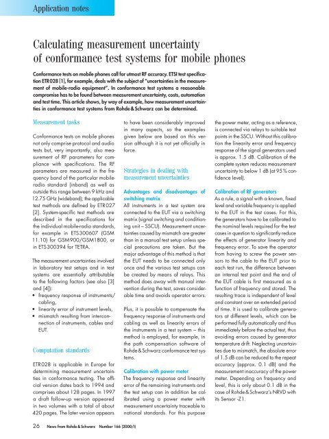
Conformance tests on mobile phones call for utmost RF accuracy. ETSI test specifi cation<br />
ETR028 [1], for example, deals with the subject of “uncertainties in the measurement<br />
of mobile-radio equipment”. In conformance test systems a reasonable<br />
compromise has to be found between measurement uncertainty, costs, automation<br />
and test time. This article shows, by way of example, how measurement uncertainties<br />
in conformance test systems from <strong>Rohde</strong> & <strong>Schwarz</strong> can be determined.<br />
Measurement tasks<br />
Conformance tests on mobile phones<br />
not only comprise protocol and audio<br />
tests but, very importantly, also measurement<br />
of RF parameters for compliance<br />
with specifi cations. The RF<br />
parameters are measured in the frequency<br />
band of the particular mobileradio<br />
standard (inband) as well as<br />
outside this range between 9 kHz and<br />
12.75 GHz (wideband); the applicable<br />
test methods are defi ned by ETR027<br />
[2]. System-specifi c test methods are<br />
described in the specifi cations for<br />
the individual mobile-radio standards,<br />
for example in ETS300607 (GSM<br />
11.10) for GSM900/GSM1800, or<br />
in ETS300394 for TETRA.<br />
The measurement uncertainties involved<br />
in laboratory test setups and in test<br />
systems are essentially attributable<br />
to the following factors (see also [3]<br />
and [4]):<br />
• frequency response of instruments/<br />
cabling,<br />
• linearity error of instrument levels,<br />
• mismatch resulting from interconnection<br />
of instruments, cables and<br />
EUT.<br />
Computation standards<br />
ETR028 is applicable in Europe for<br />
determining measurement uncertainties<br />
in conformance testing. The offi -<br />
cial version dates back to 1994 and<br />
comprises about 128 pages. In 1997<br />
a draft follow-up version appeared<br />
in two volumes with a total of about<br />
420 pages. The later version appears<br />
26 News from <strong>Rohde</strong> & <strong>Schwarz</strong> Number 166 (2000/I)<br />
to have been considerably improved<br />
in many aspects, so the examples<br />
given below are based on this version<br />
although it is not yet offi cially in<br />
force.<br />
Strategies in dealing with<br />
measurement uncertainties<br />
Advantages and disadvantages of<br />
switching matrix<br />
All instruments in a test system are<br />
connected to the EUT via a switching<br />
matrix (signal switching and conditioning<br />
unit – SSCU). Measurement uncertainties<br />
caused by mismatch are greater<br />
than in a manual test setup unless special<br />
precautions are taken. But the<br />
major advantage of this method is that<br />
the EUT needs to be connected only<br />
once and the various test setups can<br />
be created by means of relays. This<br />
method does away with manual intervention<br />
during the test, saves considerable<br />
time and avoids operator errors.<br />
Plus, it is possible to compensate the<br />
frequency response of instruments and<br />
cabling as well as linearity errors of<br />
the instruments in a test system – this<br />
method is employed, for example, in<br />
the path compensation software of<br />
<strong>Rohde</strong> & <strong>Schwarz</strong> conformance test systems.<br />
Calibration with power meter<br />
The frequency response and linearity<br />
error of the remaining instruments and<br />
the test setup can in addition be calibrated<br />
using a power meter with<br />
measurement uncertainty traceable to<br />
national standards. For this purpose<br />
the power meter, acting as a reference,<br />
is connected via relays to suitable test<br />
points in the SSCU. Without this calibration<br />
the linearity error and frequency<br />
response of the signal generators used<br />
is approx. 1.5 dB. Calibration of the<br />
complete system reduces measurement<br />
uncertainty to below 1 dB (at 95 % confi<br />
dence level).<br />
Calibration of RF generators<br />
As a rule, a signal with a known, fi xed<br />
level and variable frequency is applied<br />
to the EUT in the test cases. For this,<br />
the generators have to be calibrated to<br />
the nominal levels required for the test<br />
cases in question to signifi cantly reduce<br />
the effects of generator linearity and<br />
frequency error. To save the operator<br />
from having to screw the power sensors<br />
to the cable to the EUT prior to<br />
each test run, the difference between<br />
an internal test point and the end of<br />
the EUT cable is fi rst measured as a<br />
function of frequency and stored. The<br />
resulting trace is independent of level<br />
and constant over an extended period<br />
of time. It is used to calibrate generators<br />
at different levels, which can be<br />
performed fully automatically and thus<br />
immediately before the actual test, thus<br />
avoiding errors caused by generator<br />
temperature drift. Neglecting uncertainties<br />
due to mismatch, the absolute error<br />
of 1.5 dB can be reduced to the repeat<br />
accuracy (approx. 0.1 dB) and the<br />
measurement inaccuracy of the power<br />
meter. Depending on frequency and<br />
level, this is only about 0.1 dB in the<br />
case of <strong>Rohde</strong> & <strong>Schwarz</strong>’s NRVD with<br />
its Sensor -Z1.