English - Rohde & Schwarz
English - Rohde & Schwarz
English - Rohde & Schwarz

You also want an ePaper? Increase the reach of your titles
YUMPU automatically turns print PDFs into web optimized ePapers that Google loves.
New HF DF Antenna ADD119<br />
HF DF Antenna ADD119 consists of<br />
two crossed, active loop elements and<br />
an active dipole housed in a fl at,<br />
fi berglass-reinforced plastic radome. It<br />
permits direction fi nding with a maximum<br />
error as small as 2° (rms), allowing<br />
ITU class A to be attained also<br />
in the HF range assuming an environment<br />
with suffi ciently low interference,<br />
adequate S/N ratio and vertical polarization.<br />
The directional patterns of the<br />
antenna elements make ADD119 suitable<br />
for receiving groundwaves as well<br />
as fl at skywaves. To obtain unambiguous<br />
bearings, the mast height should<br />
be no more than about 20 % of the<br />
shortest operating wavelength – higher<br />
masts, because of their self- resonance,<br />
lead to unduly large phase differences<br />
between the loop and dipole<br />
elements and thus to ambiguous results.<br />
ADD119 has the same size and connectors<br />
as VHF-UHF Antenna ADD190<br />
and is ideal for mobile and stationary<br />
applications.<br />
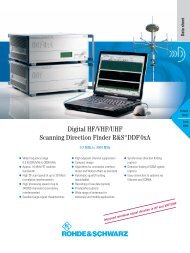
System configuration<br />
FIG 2 shows a typical system confi guration<br />
for mobile applications in the<br />
HF and VHF-UHF ranges. Antennas<br />
ADD190 and ADD071 are mounted<br />
on a telescopic mast attached to the<br />
vehicle. To minimize mutual interaction,<br />
HF Antenna ADD119 is set up on a<br />
tripod at a distance of about 40 m.<br />
ADD190 and ADD119 can be fi tted<br />
with an electronic compass (option) for<br />
automatic north alignment.<br />
To confi gure a system with only one<br />
mast – for example in stationary applications<br />
– with ADD190 mounted at the<br />
top of the mast, the disturbing effect of<br />
the mast in the HF range can be eliminated<br />
by using two Antennas ADD119<br />
on opposite sides of the mast in conjunction<br />
with Combiner GX119.<br />
Connection Board GX190 comprises<br />
a control-signal distributor plus an RF<br />
selector for 0.1 MHz to 3000 MHz,<br />
Compass<br />
GH150<br />
DF Antenna<br />
ADD 071<br />
(1300 MHz to<br />
3000 MHz)<br />
which connects one of maximally six<br />
antennas to the output. This is usually<br />
done by automatic control from DF Unit<br />
EBD190, but the system can also be<br />
confi gured for control via an RS-232-C<br />
interface.<br />
Special features<br />
DF Antenna ADD190 (20 MHz to 1300 MHz)<br />
RF<br />
IF<br />
HF DF Antenna ADD119<br />
Tripod<br />
AP502Z2<br />
Connection Board GX190<br />
Receiver<br />
Control<br />
TTL parallel<br />
DF Unit<br />
EBD190<br />
DF Unit EBD190 comes with a frontpanel<br />
keypad and LC display for convenient,<br />
straightforward operation. The<br />
receiver is operated separately; interfaces<br />
for antenna range selection are<br />
supported however. Sequential scanning<br />
of the antenna elements during<br />
Condensed data of DDF190<br />
Frequency range 0.5 MHz to 3000 MHz with three antennas<br />
and suitable receiver<br />
Polarization vertical<br />
DF accuracy 2° (rms) 0.5 MHz to 80 MHz<br />
1° (rms) 80 MHz to 1300 MHz<br />
2° (rms) 1.3 GHz to 3 GHz<br />
DF sensitivity (< 5° bearing fl uctuation<br />
(rms), 5 s integration time) 0.5 MHz to 30 MHz: 5 µV/m to 15 µV/m<br />
(frequency-dependent)<br />
20 MHz to 3000 MHz: 1 µV/m to 10 µV/m<br />
(frequency-dependent)<br />
Bandwidths HF: 0.25/0.5/1/3/5 kHz<br />
VHF/UHF: 1/2.5/8/25/100 kHz<br />
Reader service card 166/05<br />
Compass<br />
GH150<br />
RS-232-C<br />
FIG 2 Typical confi guration of mobile DF<br />
system for 0.5 MHz to 3000 MHz<br />
Articles<br />
the DF process leads to noise in the<br />
AF signal of the receiver typical of<br />
single-receiver direction fi nders. For<br />
undisturbed monitoring of the useful<br />
signal, the scanning function and thus<br />
direction fi nding can be switched off<br />
(AF/DF key).<br />
In most cases DF accuracy can be<br />
substantially improved, especially with<br />
noisy or disturbed signals, by choosing<br />
an appropriate averaging time<br />
(between 0.1 s and 5 s) and performing<br />
signal-matched fi ltering in DDF190<br />
(from 0.5 kHz to 100 kHz). Three<br />
operating modes (NORmal, CONTinuous,<br />
GATE) and several display modes<br />
(polar, numerical, histogram) are available<br />
for further optimization of direction<br />
fi nding for various types of application.<br />
A newly implemented Q (quality)<br />
fi lter effectively suppresses wild bearings.<br />
A realtime clock allows a time<br />
stamp to be output together with each<br />
bearing. This makes for easier allocation<br />
of information in networked DF<br />
and location systems.<br />
Franz Demmel; Ulrich Unselt<br />
REFERENCES<br />
[*] Demmel, Franz; Wille, Raimund: Digital<br />
direction fi nding from 20 to 3000 MHz to<br />
ITU guidelines. News from <strong>Rohde</strong> & <strong>Schwarz</strong><br />
(1996) No. 152, pp 30 – 32<br />
News from <strong>Rohde</strong> & <strong>Schwarz</strong> Number 166 (2000/I) 17