Introduction to Microcontrollers
Introduction to Microcontrollers
Introduction to Microcontrollers

Create successful ePaper yourself
Turn your PDF publications into a flip-book with our unique Google optimized e-Paper software.
2.4. ANALOG I/O 43<br />
111<br />
110<br />
101<br />
100<br />
011<br />
010<br />
001<br />
000<br />
code<br />
Vref<br />
/8<br />
= 1 lsb<br />
(a)<br />
Vref<br />
V in<br />
110<br />
101<br />
100<br />
011<br />
010<br />
001<br />
code<br />
(1)<br />
(1)<br />
(2)<br />
τ s 2τ s 3τ s 4τ<br />
s<br />
(b)<br />
V in<br />
111 7 lsb<br />
000<br />
6 lsb<br />
5 lsb<br />
4 lsb<br />
3 lsb<br />
2 lsb<br />
Vref<br />
1 lsb<br />
V ref /16<br />
t =0.5 lsb<br />
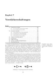
Figure 2.17: Basic idea of analog <strong>to</strong> digital conversion (r = 3, GND=0). (a) Mapping from analog<br />
voltage <strong>to</strong> digital code words, (b) example input and conversion inaccuracies.<br />
Figure 2.17 (a) shows the basic principle of analog-<strong>to</strong>-digital conversion. The analog input voltage<br />
range [GND, Vref] is parted in<strong>to</strong> 2 r classes, where r is the number of bits used <strong>to</strong> represent the digital<br />
value. Each class corresponds <strong>to</strong> a digital code word from 0 <strong>to</strong> 2 r − 1. The analog value is mapped<br />
<strong>to</strong> the representative of the class, in our case the midpoint, by the transfer function. We call r the<br />
resolution, but you will also find the term word width in the literature. Typical values for r are 8 or 10<br />
bits, but you may also encounter 12 bit and more. The lsb of the digital value represents the smallest<br />
voltage difference Vref/2 r that can be distinguished reliably. We call this value the granularity of<br />
the a/d converter, but you will often find the term resolution in the literature 6 . The class width of<br />
most classes corresponds <strong>to</strong> 1 lsb, with the exceptions of the first class (0.5 lsb) and the last class<br />
(1.5 lsb). This asymmetry stems from the requirement that the representative of the code word 0<br />
should correspond <strong>to</strong> 0 V, so the first class has only half the width of the other classes, whereas the<br />
representative of the code word 2 r − 1 should be Vref − 1 lsb <strong>to</strong> allow easy and compatible expansion<br />
<strong>to</strong> more bits. To avoid the asymmetry, we could for example use the lower bound of the class as its<br />
representative. But in this case, the worst case error made by digitization would be +1 lsb. If we use<br />
the midpoint, it is only ± 0.5 lsb.<br />
As you can see in Figure 2.17 (b), the conversion introduces some inaccuracies in<strong>to</strong> the microcontroller’s<br />
view of the analog value. First of all, the mapping of the analog value in<strong>to</strong> classes results in<br />
information loss in the value domain. Fluctuations of the analog value within a class go unnoticed, for<br />
instance both points (1) in the figure are mapped <strong>to</strong> the same code word 001. Naturally, this situation<br />
can be improved by reducing the granularity. One way <strong>to</strong> achieve this is <strong>to</strong> make r larger, at the cost<br />
of a larger word width. Alternatively, the granularity can be improved by lowering Vref, at the cost of<br />
a smaller input interval.<br />
Secondly, the conversion time, which is the time from the start of a conversion until the result of<br />
this conversion is available, is non-zero. In consequence, we get a certain minimum sampling period<br />
6 Actually, “resolution” is used very frequently, whereas “granularity” is not a term generally used, it is more common<br />
in clock synchronization applications. But <strong>to</strong> avoid confusion with the resolution in the sense of word width, we decided<br />
<strong>to</strong> employ the term granularity here as well.