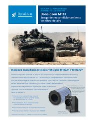
INLET BARRIER FILTER SYSTEM - Donaldson Company, Inc.
INLET BARRIER FILTER SYSTEM - Donaldson Company, Inc.
INLET BARRIER FILTER SYSTEM - Donaldson Company, Inc.

You also want an ePaper? Increase the reach of your titles
YUMPU automatically turns print PDFs into web optimized ePapers that Google loves.
Aerospace Filtration Systems, <strong>Inc</strong>.<br />
AFS-BH206B-IBF-KIT-ICA, Revision Initial Release Proprietary Information<br />
3-1. INSPECTION REQUIREMENTS<br />
3-1.1. GENERAL REQUIREMENTS<br />
a. Inspection of the IBF system consists of, in general terms, inspection of the filter<br />
assembly, inspection of the structural components, inspection of electrical and system<br />
components, and a special inspection at three specified points based on hours after initial<br />
installation. The components of the system are divided, generally as a scope of work, into<br />
Filter Assembly / Water Wash Tube / Seal, Structural Components, and Systems and<br />
Electrical components as is done throughout the manual.<br />
b. Refer to the Appendix A - Illustrated Parts Breakdown for component illustrations that<br />
provide supplemental information relative to proper assembly configuration, orientation, and<br />
locations for all components to be inspected per Chapter 3 and Table 3-1. Refer to<br />
Appendix A, Figure A-1 & A-2 for the primary kit components. Refer to Appendix A,<br />
Figures A-2, A-3 and A-5 for filters, wash tube and filter seal components. Refer to<br />
Appendix A, Figures A-5, (items 2, 9, 27 & 34 plus associated tubes, hoses, clamps and<br />
brackets) and A-12 thru A-15 for items considered the primary systems and electrical<br />
components. Refer to Appendix A, Figures A-3 (less the filter assemblies and<br />
systems/electrical components) and A-11 for items considered structural components.<br />
c. Table 3-1 gives a recommended inspection schedule for the components of the system.<br />
The Trouble-Shooting Guide, Table 8-1 found near the end of Chapter 8, also gives<br />
additional guidance when performing inspections and encountering trouble with the system.<br />
Chapter 8 also provides specific inspection guidance and removal/installation procedures for<br />
each component and is structured in the same three major groups as discussed above.<br />
3-1.2. <strong>FILTER</strong> ASSEMBLY INSPECTION<br />
a. The following inspections pertain to the barrier filter assembly and associated components,<br />
which include the filter assembly (i.e. filter frame and filter media), engine wash tube<br />
assembly, and all associated seals/fasteners.<br />
b. ON-CONDITION UP TO TIS LIMIT: Any FMA indication in the “RED”, “<strong>FILTER</strong>” light<br />
indication of the IBF cockpit indicator or failed PAC requires a conditional inspection in<br />
accordance with Table 3-1.<br />
c. VISUAL: All filter assembly components (plus engine wash tube assembly, seals and<br />
fasteners) are to be visually inspected at every annual in accordance with Table 3-1 checking<br />
for the following: filter media for tears, punctures, uneven or damaged pleats; seals for<br />
tears/damage; frame components for corrosion, cracks, distortions near holes, and check for<br />
missing or damaged fasteners.<br />
Use or disclosure of this material is subject 3-2 AFS Bell 206B IBF Instructions for Continued Airworthiness<br />
to the restrictions on the title page