INLET BARRIER FILTER SYSTEM - Donaldson Company, Inc.
INLET BARRIER FILTER SYSTEM - Donaldson Company, Inc.
INLET BARRIER FILTER SYSTEM - Donaldson Company, Inc.

Create successful ePaper yourself
Turn your PDF publications into a flip-book with our unique Google optimized e-Paper software.
Aerospace Filtration Systems, <strong>Inc</strong>.<br />
AFS-BH206B-IBF-KIT-ICA, Revision Initial Release Proprietary Information<br />
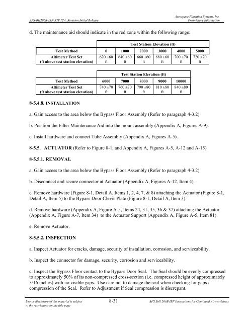
d. The maintenance aid should indicate in the red zone within the following range:<br />
Test Station Elevation (ft)<br />
Test Method 0 1000 2000 3000 4000 5000<br />
Altimeter Test Set<br />
(ft above test station elevation)<br />
620 ±60<br />
ft<br />
640 ±60<br />
ft<br />
660 ±60<br />
ft<br />
680 ±60<br />
ft<br />
700 ±70<br />
ft<br />
720 ±70<br />
ft<br />
Test Station Elevation (ft)<br />
Test Method 6000 7000 8000 9000 10000<br />
Altimeter Test Set<br />
(ft above test station elevation)<br />
8-5.4.8. INSTALLATION<br />
740 ±70<br />
ft<br />
760 ±70<br />
ft<br />
790 ±80<br />
ft<br />
810 ±80<br />
ft<br />
840 ±80<br />
ft<br />
a. Gain access to the area below the Bypass Floor Assembly (Refer to paragraph 4-3.2)<br />
b. Position the Filter Maintenance Aid into the mount assembly (Appendix A, Figures A-9).<br />
c. Install hardware and connect Tube Assembly (Appendix A, Figures A-5).<br />
8-5.5. ACTUATOR (Refer to Figure 8-1, and Appendix A, Figures A-5, A-12 and A-15)<br />
8-5.5.1. REMOVAL<br />
a. Gain access to the area below the Bypass Floor Assembly (Refer to paragraph 4-3.2)<br />
b. Disconnect and secure connector at Actuator (Appendix A, Figures A-12, Item 4).<br />
c. Remove hardware (Figure 8-1, Detail A, Items 1, 2, 4, 7, & 8) attaching the Actuator (Figure 8-1,<br />
Detail A, Item 5) to the Bypass Door Clevis Plate (Figure 8-1, Detail A, Item 3).<br />
d. Remove hardware (Appendix A, Figure A-5, Items 24, 31, 35, 36 & 37) attaching the Actuator<br />
(Appendix A, Figure A-7, Item 34) to the Actuator Support (Appendix A, Figure A-5, Item 81).<br />
e. Remove Actuator.<br />
8-5.5.2. INSPECTION<br />
a. Inspect Actuator for cracks, damage, security of installation, corrosion, and serviceability.<br />
b. Inspect the connector for damage, security, corrosion and serviceability.<br />
c. Inspect the Bypass Floor contact to the Bypass Door Seal. The Seal should be evenly compressed<br />
to approximately 50% of its non-compressed cross-section (i.e. compressed height of approximately<br />
3/16 inches) with no visible gaps. Use care not to damage the seal when checking for gaps /<br />
compression of the Seal. Refer to Adjustment if Seal compression is discrepant.<br />
Use or disclosure of this material is subject 8-31 AFS Bell 206B IBF Instructions for Continued Airworthiness<br />
to the restrictions on the title page