INLET BARRIER FILTER SYSTEM - Donaldson Company, Inc.
INLET BARRIER FILTER SYSTEM - Donaldson Company, Inc.
INLET BARRIER FILTER SYSTEM - Donaldson Company, Inc.

You also want an ePaper? Increase the reach of your titles
YUMPU automatically turns print PDFs into web optimized ePapers that Google loves.
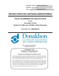
Aerospace Filtration Systems, <strong>Inc</strong>.<br />
AFS-BH206B-IBF-KIT-ICA, Revision Initial Release Proprietary Information<br />
a. Gain access to the top side of the Bypass Floor Assembly (Refer to paragraph 4-3.1).<br />
b. Connect a Barfield (or equivalent) altimeter test set vacuum system to the plenum tube assembly<br />
(Appendix A, Figure A-9, Item 3), by slipping a piece of 3/16 inch ID vinyl tubing over the end of<br />
the tube assembly. Ensure that the fit between the tubing and tube assembly is tight, i.e., no<br />
leakage.<br />
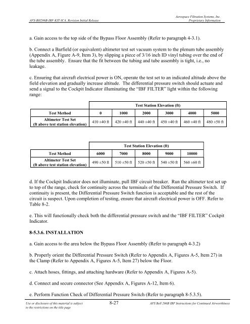
c. Ensuring that aircraft electrical power is ON, operate the test set to an indicated altitude above the<br />
field elevation and gradually increase altitude. The differential pressure switch should actuate and<br />
send a signal to the Cockpit Indicator illuminating the “IBF <strong>FILTER</strong>” light within the following<br />
range:<br />
d. If the Cockpit Indicator does not illuminate, pull IBF circuit breaker. Run the altimeter test set up<br />
to top of the range, check for continuity across the terminals of the Differential Pressure Switch. If<br />
continuity is present, the Differential Pressure Switch function is acceptable and the rest of the<br />
circuit is suspect. Upon completion of testing, ensure that aircraft electrical power is OFF. Refer to<br />
Table 8-2.<br />
e. This will functionally check both the differential pressure switch and the “IBF <strong>FILTER</strong>” Cockpit<br />
Indicator.<br />
8-5.3.6. INSTALLATION<br />
Test Station Elevation (ft)<br />
Test Method 0 1000 2000 3000 4000 5000<br />
Altimeter Test Set<br />
(ft above test station elevation)<br />
410 ±40 ft 420 ±40 ft 440 ±40 ft 450 ±40 ft 460 ±40 ft 480 ±50 ft<br />
Test Station Elevation (ft)<br />
Test Method 6000 7000 8000 9000 10000<br />
Altimeter Test Set<br />
(ft above test station elevation)<br />
490 ±50 ft 510 ±50 ft 520 ±50 ft 540 ±50 ft 560 ±60 ft<br />
a. Gain access to the area below the Bypass Floor Assembly (Refer to paragraph 4-3.2)<br />
b. Properly orient the Differential Pressure Switch (Refer to Appendix A, Figures A-5, Item 27) in<br />
the Clamp (Refer to Appendix A, Figures A-5, Item 27) below the Floor.<br />
c. Attach hoses, fittings, and attaching hardware (Refer to Appendix A, Figures A-5).<br />
d. Connect and secure connector (See Appendix A, Figures A-12, Item 6).<br />
e. Perform Function Check of Differential Pressure Switch (Refer to paragraph 8-5.3.5).<br />
Use or disclosure of this material is subject 8-27 AFS Bell 206B IBF Instructions for Continued Airworthiness<br />
to the restrictions on the title page