Manual MR3140-M - DResearch
Manual MR3140-M - DResearch
Manual MR3140-M - DResearch

Create successful ePaper yourself
Turn your PDF publications into a flip-book with our unique Google optimized e-Paper software.
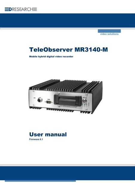
TeleObserver <strong>MR3140</strong>-M<br />
Mobile hybrid digital video recorder<br />
User manual<br />
Firmware 6.1<br />
video solutions
<strong>DResearch</strong> – User <strong>Manual</strong> TeleObserver <strong>MR3140</strong>-M 2011-02-03<br />
This document may not be copied, reproduced, summarised, translated or otherwise reproduced<br />
without the express permission of <strong>DResearch</strong>. It has been compiled to the best knowledge of<br />
<strong>DResearch</strong>. <strong>DResearch</strong> is not responsible for the consequences of typographical or residual errors<br />
relating to the user manual which is only informative in nature.<br />
<strong>DResearch</strong> retains the right to make amendments to the contents of the user manual without having<br />
any duty to inform third parties. Any change made to the product or its associated software not<br />
expressly confirmed by <strong>DResearch</strong> will result in the termination of the operating licence and warranty.<br />
Any company and/or product names are trade names and or legally protected trade marks of the<br />
relevant manufacturer.<br />
© Copyright 2011 <strong>DResearch</strong> Fahrzeugelektronik GmbH. All rights reserved.<br />
2
<strong>DResearch</strong> – User <strong>Manual</strong> TeleObserver <strong>MR3140</strong>-M 2011-02-03<br />
C O N T E N T S<br />
1 General information about <strong>DResearch</strong> video systems............................................................. 5<br />
1.1 System overview and new functions in this version............................................................... 6<br />
1.2 Scope of delivery.................................................................................................................... 7<br />
1.3 Accessories & additional devices........................................................................................... 7<br />
1.4 Safety advice.......................................................................................................................... 8<br />
1.5 Warranty................................................................................................................................. 9<br />
1.6 Certifications, standards and conformities ............................................................................. 9<br />
1.7 Scope of use ........................................................................................................................ 10<br />
1.8 General installation information............................................................................................ 10<br />
1.9 Temperature range .............................................................................................................. 11<br />
1.10 System components and device features ............................................................................ 12<br />
2 The recording device <strong>MR3140</strong>-M in detail ................................................................................ 15<br />
2.1 Device description................................................................................................................ 15<br />
2.2 Changing and inserting the removable disk......................................................................... 16<br />
2.3 Significance of the status LEDs ........................................................................................... 17<br />
2.4 Device interfaces.................................................................................................................. 18<br />
2.4.1 Analogue video inputs 1 ... 4 – connection of analogue CCTV cameras ........................ 18<br />
2.4.2 LAN Interface – connection of IP network cameras or other devices.............................. 18<br />
2.4.3 Video Out 1 and 2 – connection of control monitors ....................................................... 19<br />
2.4.3.1 Sequential video output and multiviews.................................................................. 19<br />
2.4.3.2 Display of information and system events (OSD) ................................................... 20<br />
2.4.4 Power supply for the device and cameras....................................................................... 21<br />
2.4.5 COM 1 – Serial data transmission and GPS connection................................................. 22<br />
2.4.6 COM 2 Interface – External modem connection............................................................. 22<br />
2.4.7 COM 3 and COM 4–Interface (IBIS and RS485)............................................................. 22<br />
2.4.8 The audio interface .......................................................................................................... 23<br />
2.4.9 GPIO-interface – detector inputs and switch relay outputs ............................................. 23<br />
2.4.10 GPIO-Interface ............................................................................................................ 24<br />
2.4.11 “Ext. Devices“ Interface – IBIS, CAN and RS485 ....................................................... 25<br />
3 Device Configuration - The main programm CMS and its main menu.................................. 26<br />
3.1 SystemManagement –module for device configuration....................................................... 27<br />
3.1.1 The device configuration.................................................................................................. 29<br />
3.1.1.1 System :: Basic settings .......................................................................................... 31<br />
3.1.1.2 System :: Time ....................................................................................................... 34<br />
3.1.1.3 System :: Passwords............................................................................................... 35<br />
3.1.1.4 System :: Version .................................................................................................... 36<br />
3.1.1.5 Devices :: Cameras................................................................................................. 36<br />
3.1.1.6 Devices :: IP-Cameras ............................................................................................ 39<br />
3.1.1.7 Devices :: Detectors ................................................................................................ 41<br />
3.1.1.8 Devices :: Relays .................................................................................................... 42<br />
3.1.1.9 Devices :: Audio ...................................................................................................... 42<br />
3.1.1.10 Connectors :: GPS.............................................................................................. 43<br />
3.1.1.11 Connectors :: Network ........................................................................................ 44<br />
3.1.1.12 Video output :: MultiView .................................................................................... 45<br />
3.1.1.13 Video output :: Transfer order............................................................................. 45<br />
3.1.1.14 Activations........................................................................................................... 46<br />
3.1.1.15 System events .................................................................................................... 48<br />
3.2 The web interface of the system .......................................................................................... 51<br />
3
<strong>DResearch</strong> – User <strong>Manual</strong> TeleObserver <strong>MR3140</strong>-M 2011-02-03<br />
4 Relevant comments on the daily operation ............................................................................. 52<br />
4.1 Power supply and shutdown of the systems .................................................................. 52<br />
4.2 Hold-back time of the permanent recordings versus data privacy .............................. 52<br />
4.3 Shutdown behaviour of the system ................................................................................. 53<br />
4.3.1 Shutdown behaviour during permanent and alarm recordings........................................ 53<br />
4.3.2 Shutdown behaviour during data research...................................................................... 54<br />
4.3.3 Influencing of the recording during data research ........................................................... 54<br />
4.4 Overheat protection: temperature shutdown level of the system......................................... 55<br />
4.5 Default configuration for factory reset .................................................................................. 55<br />
5 Update & Reset, maintenance, problem analysis and technical support............................. 56<br />
5.1 Update of the device via the update tool.............................................................................. 56<br />
5.2 Update and Reset of the device via the web interface ........................................................ 56<br />
5.3 Maintenance, cleaning and care of the system.................................................................... 57<br />
5.4 Problem analysis and resolution .......................................................................................... 58<br />
5.5 Technical support by the manufacturer................................................................................ 59<br />
6 Technical data of the <strong>MR3140</strong>-M ............................................................................................... 60<br />
7 Technical drawing ...................................................................................................................... 62<br />
8 Abbreviations.............................................................................................................................. 63<br />
4
<strong>DResearch</strong> – User <strong>Manual</strong> TeleObserver <strong>MR3140</strong>-M 2011-02-03<br />
1 General information about <strong>DResearch</strong> video systems<br />
Congratulations on the acquisition of your <strong>MR3140</strong>-M!<br />
Dear customer, thank you for deciding to purchase an <strong>MR3140</strong>-M mobile hybrid recorder, we are most<br />
grateful for your custom. You have made an excellent choice in acquiring this device, a top quality<br />
product from <strong>DResearch</strong>. The <strong>MR3140</strong>-M is a compact digital unit for recording video sequences from<br />
analogue and digital cameras as well as other associated data (IBIS and GPS). With industrial styling<br />
and a robust nature, the device is intended for mobile and static use under the severest conditions.<br />
Because of the particular application requirements of mobile CCTV monitoring, the <strong>MR3140</strong>-M is<br />
designed to be a compact, efficient system with a long service life.<br />
Owing to its tolerance of temperature variations and its resistance to vibration and shocks, corrosion,<br />
dust and moisture, the unit is particularly well equipped for flexible use in vehicles. The system<br />
digitizes and records up to 4 analogue video streams. Alternatively up to 8 digital video streams from<br />
IP cameras can be recorded from a local network. The <strong>MR3140</strong>-M also has many interfaces for<br />
configuration, expansion, maintenance and integration in all-in-one systems. As many as 12 IP<br />
cameras can be set up in the network for display on a control room monitor.<br />
Please take some time to read the user manual carefully so that you are familiar with the complete<br />
functional scope of the system and its application requirements. The documentation for the device is<br />
provided on the software CD supplied with the device.<br />
We wish you every success in working with the <strong>MR3140</strong>-M mobile hybrid recorder!<br />
<strong>DResearch</strong> devices at a glance MR3060* <strong>MR3140</strong> MR3180 TO1200* TO3100<br />
Analogue recording yes yes yes - yes<br />
Digital recording - yes yes - -<br />
Video-IN analogue (max.) 6 4 8 4 8<br />
Video-IN digital (max.) - 8 8 - -<br />
Video-OUT 1 2 2 - 1<br />
Transmission via SMS, Video (GSM, yes *** yes *** yes *** yes ** yes **<br />
GPRS, EDGE) if an alarm is triggered<br />
GPS data recording yes yes yes yes yes **<br />
IBIS data recording yes yes yes - yes **<br />
Max. capacity HD in GB 500 250 250 - 160<br />
Motion detection yes yes yes - -<br />
Sabotage detection yes yes yes - -<br />
Encryption/digital signature yes yes yes yes yes<br />
Digital inputs 6 6 8 6 8<br />
Digital outputs/switch relays 4 4 2 4 6<br />
RS232/485 yes yes yes yes yes<br />
Video management software incl. yes yes yes yes yes<br />
* The system TO1200 is no longer available from 2010, the system MR3060 is available from 2010.<br />
** optional, depends on type of device and/or software module key<br />
*** only for SMS transmission via external device<br />
5
<strong>DResearch</strong> – User <strong>Manual</strong> TeleObserver <strong>MR3140</strong>-M 2011-02-03<br />
1.1 System overview and new functions in this version<br />
System overview<br />
� Recording of video, audio, IBIS, GPS<br />
� Hybrid mode: recording of up to 8 analogue and digital camera signals<br />
� Formats - analogue: H264, CIF + 2CIF; digital: MJPEG, up to 1 MPx<br />
� Hard disks: HDD / SSD (S-ATA) with capacity between 80 and 250 GB<br />
� Recording into separated archives (alarm, pre-alarm, ring)<br />
� Automatic deleting of archives, configurable hold-back time and maximum recording time<br />
� Operating modes: pause, continuous recording, sleep<br />
� Selftest of the unit and automatic securing of the data integrity<br />
� Digital inputs for switches / buttons and alarm detectors<br />
� Digital relay outputs to switch external devices<br />
� Robust and fanless design, vandal safe<br />
� Vehicle fit and certified in accordance to e1 and EN50155<br />
� Extensive configuration options<br />
� Ethernet interfaces, serial interface RS232, 485<br />
� Sending SMS in the case of an alarm and for defined system events<br />
� Data security: multi-level access protection, digital signing of the recorded data<br />
� Numerous detectors for system disorders, motion and sabotage detection for analogue cameras<br />
� Logically combinable system detectors and allocation of defined actions<br />
� And much more…<br />
A detailed overview of the possibilities of the system is given in this document and further<br />
information materials, like system description or application concepts from <strong>DResearch</strong> –<br />
request them or visit us on our website:<br />
www.<strong>DResearch</strong>.de<br />
New features in this firmware – version 6.1<br />
� Suspension of the overheating protection: The upper temperature shutdown level can be<br />
increased – during the update – with the update tool from +55°C to +70°C. Please note the<br />
instruction of the update tool and the corresponding annotations in this document.<br />
� Definable default configuration: During the update with the update tool you can specify if the<br />
factory settings of the manufacturer or the current configuration of the system shall be defined as<br />
default configuration. This default configuration will be loaded by a factory reset. Please note the<br />
instruction of the update tool and the corresponding annotations in this document.<br />
6
<strong>DResearch</strong> – User <strong>Manual</strong> TeleObserver <strong>MR3140</strong>-M 2011-02-03<br />
1.2 Scope of delivery<br />
� Digital hybrid recorder<br />
� Removable hard disk (capacity between 80 – 250 GB)<br />
� Software for configuration and analysis (Central Monitoring Software - CMS)<br />
� Licences for the CMS<br />
� Product CD with software and documentation<br />
1.3 Accessories & additional devices<br />
The devices can be expanded with various accessories. For a detailed list of all the accessories<br />
offered by <strong>DResearch</strong>, please refer to the current product catalogue. For other information and<br />
ordering of accessories please contact your system integrator or our team direct.<br />
Assortment of additional devices for the system:<br />
� Power supply unit 24V/2,5A<br />
� Power – plug (ready-made 75cm cable with pin sleeves)<br />
� Miscellaneous mounting material<br />
� Service cable (crosslink and patch cables, serial service cable)<br />
� Plug set GPIO, plug set Ext. Device<br />
� Power-over-Ethernet switch (PoE) for supplying power to IP cameras<br />
� DC/DC transformer (various input voltages, Out: 12-24V)<br />
� Hard disks HDD/SSD: 80 - 250 GB<br />
� Video- and network cables (CAT 5; 6 ) in various lengths<br />
� GPIO tester<br />
Assortment of additional devices to extend the system:<br />
� WLAN modules<br />
� GPS receiver, GSM antenna in various versions<br />
� UMTS/GPRS/HSDPA/HSUPA modems for data transfer<br />
� Coupling systems for bridging vehicle clutches<br />
� Various analogue and IP network cameras<br />
� Coloured and b&w surveillance monitors for fitting into vehicles (trucks, buses,<br />
trams, trains)<br />
A complete installation in a rail carriage when expanded with accessories could look like this:*<br />
* This is an illustrative example of the MR3180 – the <strong>MR3140</strong>-M works with a maximum of four analogue cameras.<br />
7
<strong>DResearch</strong> – User <strong>Manual</strong> TeleObserver <strong>MR3140</strong>-M 2011-02-03<br />
1.4 Safety advice<br />
Incorrect handling can, at its worst, lead to personal injury or destruction of the device, and/or the<br />
termination of the guarantee. Therefore please be sure to note and follow the advice below before<br />
operating the device.<br />
� Never try to insert objects into any device openings since this could cause short-circuits or<br />
deliver electric shocks because of the voltage inside the unit.<br />
� Only use original parts or products recommended by the manufacturer in the operation of<br />
the equipment. If you have a problem please consult your system integrator.<br />
� Avoid installing equipment where it could be exposed to excessive smoke, dust, vibration,<br />
chemicals, moisture, heat, direct sunlight or electromagnetic fields. Such exposure can have<br />
a detrimental effect on the operation of the device and – in the worst case – can cause<br />
damage to the device.<br />
� Never operate the device in locations where there is a danger that water might penetrate the<br />
device.<br />
� When connecting up the device with the peripherals ensure that the cable is not under<br />
tension. Ensure all cables are installed properly.<br />
� Only remove the hard disk from the device when all the LEDs on the front panel are off. To<br />
remind you this warning is printed on the front of the removable hard disk.<br />
Remove only, when all LEDs are off!<br />
This is an (EMC, EN 55022) Class B system and can be used in all environments.<br />
8
<strong>DResearch</strong> – User <strong>Manual</strong> TeleObserver <strong>MR3140</strong>-M 2011-02-03<br />
1.5 Warranty<br />
The warranty terms for materials and manufacturing faults are, unless otherwise agreed by special<br />
negotiation, set out by <strong>DResearch</strong> Fahrzeugelektronik GmbH in its General Terms and Conditions.<br />
The General Terms and Conditions are to be found in the documents supplied. No further, expressed<br />
or tacit guarantees are accepted. The manufacturer is not responsible for claims arising from the<br />
improper handling or faulty installation by third parties.<br />
The warranty is terminated if repairs or interventions are made by people who have not been<br />
authorised by the manufacturer. Claims arising from the inappropriate use of the equipment, incorrect<br />
maintenance or the use of accessories not recommended by the manufacturer are not covered under<br />
the terms of the warranty.<br />
Opening the device inevitably leads to the cancellation of all existing guarantee cover, guaranteed<br />
rights and agreed warranties.<br />
The supplied software and installation pack presuppose a conflict-free operating system. Solving<br />
problems relating to this require detailed knowledge of the systems used or their complete<br />
reinstallation. The manufacturer makes no guarantees that programs or systems operated by the user<br />
will deliver the desired benefits.<br />
If a product is returned under the terms of the warranty this is always to be agreed in advance with the<br />
supplier, otherwise the return will not be processed. If returning an item, you will be given a returns<br />
number which is to be used throughout the procedure. The manufacturer takes no responsibility for<br />
damage or insurance during transit. Cash on delivery and ‘carriage forward’ shipments are not<br />
accepted.<br />
1.6 Certifications, standards and conformities<br />
The device is made to current safety and reliability standards (state: 09/2008) for use in a variety of<br />
environments. It was designed specially for use in trucks and locomotives and meets current<br />
requirements of various European standards.<br />
Certifications, standards and conformities:<br />
� CE compliant to EN55022 class B<br />
� RoHS conformity<br />
� Conformity to European rail standard EN50155<br />
� e1 certification from the German Federal Bureau of Motor Vehicles and Drivers (KBA)<br />
� Conformity to European EMC guidelines<br />
� Vibration IEC 61373 (9) and shock IEC 61373 (10.5)<br />
� Heat & fire resistance DIN 53438-2, DIN 5510-2<br />
9
<strong>DResearch</strong> – User <strong>Manual</strong> TeleObserver <strong>MR3140</strong>-M 2011-02-03<br />
1.7 Scope of use<br />
Public transport sectors<br />
Trams, suburban railways, underground railways, buses, local and long distance trains and other vehicles<br />
Distribution, logistics and transport sectors<br />
Secure cash transport, transportation of hazardous loads, trailers and storage areas, high-bay warehousing and<br />
distribution centres, etc.<br />
Housing and construction industry<br />
Local properties, lifts and entrance halls as well as building sites.<br />
Industry and commerce<br />
Builders yards, industrial sites, waterworks and water treatment works, pumping stations, power stations,<br />
transformer substations, wind farms, geothermal power stations, retail branches, shopping centres, etc.<br />
Maritime - Offshore<br />
Locks, sea level measuring stations, oil drilling platforms, off-shore wind farms, etc.<br />
Private sector<br />
Holiday cottages, residential property, bungalows, boats, yachts, other vessels.<br />
Caravans, camper vans, etc.<br />
1.8 General installation information<br />
Power supply<br />
� The device must be plugged into a buffered power supply (UPS or unswitched supply/permanent<br />
positive).<br />
� Do NOT use the on board train power supply switch to turn the system on. Use the ignition.<br />
� Ensure that the device is wired up exactly as described in the manual.<br />
Ensure there is a constant power supply of 12-24 VDC. Temporary power outages will be tolerated<br />
by the device but they are always to be avoided and can lead to system failures and permanent<br />
damage to the equipment (e.g. from lack of proper vehicle battery maintenance).<br />
The UPS must be a device which has been recommended by the manufacturer and has valid<br />
certification for the application type.<br />
Any damage resulting from disregarding this advice will not be covered by any guarantee or<br />
warranty.<br />
Cable length between device and cameras<br />
Long connection paths between device and cameras have detrimental effects on the quality of the<br />
video signals. Select camera positions so that as much as possible of the area to be monitored can be<br />
covered with minimum cable lengths. Your system integrator will help you with the design of the<br />
system.<br />
10
<strong>DResearch</strong> – User <strong>Manual</strong> TeleObserver <strong>MR3140</strong>-M 2011-02-03<br />
Ventilation and cooling<br />
Avoid installations where heat can build up. The equipment is designed to function without the need<br />
for a fault-prone fan, but adequate air circulation needs to be provided round the cooling fins.<br />
Mounting<br />
The system is equipped with an automatic overheating protection. In this case the system will be<br />
shut down automatically and controlled if the internal temperature is 55°C. Please note that the<br />
internal temperature may be up to 15°C above the am bient temperature.<br />
Select the installation place so that heat accumulations can be avoided and the system is<br />
sufficiently cooled by air circulation. Further information about overheating protection you will find<br />
at the end of this document.<br />
The device has 2 guide rails on the top and bottom which take mounting screws. If at all possible,<br />
mount the device on a mounting plate which can also take the necessary additional components such<br />
as a transformer and connection block.<br />
The device must not be mounted with the hard disk drive aperture facing down! When fitting<br />
ensure that it is possible to change the removable hard disks easily!<br />
1.9 Temperature range<br />
Storage temp.: maximum + 70°C<br />
Operating temp.: 0°C to + 55°C (normal HDD)<br />
0°C to + 70°C (HT- HDD, SSD)<br />
Humidity: 10 … 90 % (not condensed)<br />
When using conventional data storage devices (HDD) the unit will automatically shut down when it<br />
reaches its temperature limit of + 55°C (for normal HDD) in order to protect the hard disk.<br />
When the temperature reduces to below this limit, the device will automatically switch back on.<br />
This temperature-dependent switching event is stored in a log file.<br />
11
<strong>DResearch</strong> – User <strong>Manual</strong> TeleObserver <strong>MR3140</strong>-M 2011-02-03<br />
1.10 System components and device features<br />
The complete system consists of three different modules which communicate with each other via a<br />
proprietary software data protocol which is the same irrespective of the operating system.<br />
The device <strong>MR3140</strong>-M<br />
� Data recording and storage of video streams with metadata according to the<br />
predetermined configuration<br />
� Storage on a removable hard disk<br />
� Connection of up to two control monitors<br />
� Function and configuration: see following chapters<br />
� Default IP address of the device when shipped: 192.168.0.1<br />
Service computer and analysis station<br />
Usually the review station is used for analysing the recorded data. A service laptop is often employed for<br />
installation, configuration and system maintenance. A standard commercial computer can be used.<br />
Currently <strong>DResearch</strong> offers two software packages:<br />
Central Management Software (CMS)<br />
with the modules Vision, ImageFinder and SystemManagement for<br />
� Visualisation of recorded data (video, add. data)<br />
� Searching recorded data according to freely configurable parameters (e.g. time, events etc.)<br />
� Display of live video sequences (incl. additional data)<br />
� Device configuration<br />
� Operating systems (OS) supported: Windows XP Prof. and Vista<br />
ImageFinderNX<br />
The analysis software ImageFinder NX is the successor of the CMS module ImageFinder<br />
and provides a convenient search and analysis of the recorded data. The software is<br />
usable in conjunction with the USB-TTU. A direct search at the device is possible from<br />
version 1.5. The usage requires Windows operating systems Windows XP Prof. (SP 2)<br />
or Vista.<br />
The previous CMS module ImageFinder will be developed only until the end of 2009 and<br />
then discontinued!<br />
The TeleObserver Transfer Unit (USB-TTU)<br />
This separate device (USB-TTU) has the following uses:<br />
� Taking the removable hard disk for the evaluation/analysis of data.<br />
� Formatting the hard disk.<br />
� Activating removable hard disks and decoding data (when using DR.Secure<br />
encryption).<br />
� Displaying synchronous video images.<br />
� Analysing of the recorded data (video, audio, add. Data, such as IBIS and GPS).<br />
� Creating backups.<br />
� Export of video data, printing of pictures etc.<br />
(For a detailed description of all the features have a look in the manual of the USB-TTU.)<br />
12
<strong>DResearch</strong> – User <strong>Manual</strong> TeleObserver <strong>MR3140</strong>-M 2011-02-03<br />
Detailed information you will find in this manual and the data sheet.<br />
System specification – an overview<br />
� Hybrid recorder for recording video, audio and metadata, designed for buses, trains, trams and other<br />
vehicles, certified to e1 and EN 50155<br />
� 4 x video-in analogue (BNC), 8 x video-in to record from IP network cameras (AXIS, Mobotix and others<br />
up to 1 Megapixel, 1280 x 1024 Pixel)<br />
� 2 channel audio recording (e.g. for the documentation of the driver communication)<br />
� Removable hard disk HDD / SSD: up to 250 GB HDD<br />
� 2 x video-OUT for analogue and up to 12 IP network cameras, split screen display and<br />
onward signal switching<br />
� Recording of metadata such as IBIS (VDV 300), GPS<br />
� Interfaces: RS232, RS485, Ethernet, IBIS<br />
� 6 digital alarm inputs (for alarm triggering devices) and 4 digital outputs (for switch relays)<br />
� Integrated power supply for 4 analogue cameras<br />
� Compact, robust industrial design for use in the most difficult conditions with protection against vibration<br />
� Safe from vandalism through stable cast aluminium housing (continuous casting)<br />
� Maintenance-free through fan-free operation<br />
Software and data management<br />
� Live video pictures, search and playback function and fast video download via an Ethernet-interface<br />
� Configuration and management software with ergonomic graphical user interface<br />
� Expanded event and information management, including IBIS / GPS metadata<br />
� Support for alarm and fleet management<br />
� Data encryption, watermark, sabotage recognition, role-based access management, motion detection<br />
� Flash based real-time operating system and hardware control system<br />
� MJPEG and H.264+ (MPEG-4 AVC) picture compression with recording rates up to 200 frames per<br />
second<br />
� SMS support for alarm events as well as for maintenance/service-support (GSM modem required)<br />
13
<strong>DResearch</strong> – User <strong>Manual</strong> TeleObserver <strong>MR3140</strong>-M 2011-02-03<br />
Feature Description<br />
Configurable video<br />
recording<br />
Configurable picture<br />
resolution (picture<br />
format)<br />
Configurable picture<br />
quality<br />
Configurable alarm<br />
recording<br />
Activated alarm<br />
recording display<br />
Configurable metadata<br />
recording<br />
Calling up status<br />
information<br />
Display of the event<br />
log<br />
� Recording of video sequences from up to 8 cameras (hybrid operation of<br />
analogue and IP cameras) in automatic generated archives (one ring, alarm<br />
and pre-alarm archive per camera).<br />
� Maximum of 25 pictures/s for analogue cameras to the 4 video inputs<br />
� Recording of up to 8 IP cameras with a maximum of 25 pictures/s per camera<br />
� Definable setting for maximum age for the video footage.<br />
The picture format has to be determined before recording begins!<br />
� Recording formats from analogue cameras:<br />
� CIF (352 x 288 = 101 376 Pixels)<br />
� Half frame/2CIF (704 x 288 = 202 752 Pixels)<br />
� Recording formats from IP cameras:<br />
The IP camera picture format has to be determined in the camera set up – not<br />
via CMS!<br />
� For each analogue camera there are 5 different settings for the picture quality of<br />
the recorded video footage.<br />
� The picture quality from the IP cameras is determined by the camera<br />
configuration settings.<br />
� Pre- and post-alarm recording times are configurable.<br />
� Events can be used to start alarm recording.<br />
� Data recorded with this feature are marked as such. The alarm footage is not<br />
automatically overwritten.<br />
� The maximum age of the alarm sequences can be determined.<br />
� If alarm recording is activated, this is indicated by the yellow HD LED and it is<br />
displayed on the control monitor.<br />
� Besides video footage, additional data such as date/time, camera name, IBIS<br />
and GPS data can be recorded.<br />
� Information about the current status of the device is indicated via the devices<br />
LEDs and displayed on a control monitor (OSD).<br />
� Information about the device is recorded in the event log. The log can be<br />
viewed in the searching software.<br />
System events � Indicate the various device and archive conditions. They can be viewed on a<br />
control monitor (OSD).<br />
Motion detection � Trigger-level-controlled motion detection<br />
� Motion detection can be limited by masking off particular areas of the picture.<br />
� Configurable actions in response to motion detection e.g. alarm recording<br />
and/or switching relays.<br />
Camera sabotage � Trigger-level-controlled camera sabotage detection (only for analogue cameras)<br />
� Configurable actions in response to camera sabotage, e.g. relay switching,<br />
sending SMS.<br />
14
<strong>DResearch</strong> – User <strong>Manual</strong> TeleObserver <strong>MR3140</strong>-M 2011-02-03<br />
2 The recording device <strong>MR3140</strong>-M in detail<br />
2.1 Device description<br />
The <strong>MR3140</strong>-M is one part of the complete recording system and works without a fan. The housing is<br />
made from non-rusting, maintenance-free material. The data transmission and recording processes in<br />
the device are encrypted to prevent unauthorised access to the data. The file and security operating<br />
systems used prevent loss of important files if there is a power outage and therefore maintain<br />
continuity.<br />
The device forms the switching centre and link between all other system components. It provides the<br />
interfaces for the connection of cameras, peripherals such as WLAN modem, GSM modem, PoE<br />
switch, driver monitors, relays and switches as well as other components.<br />
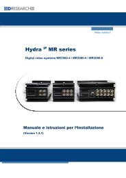
Front view of the <strong>MR3140</strong>-M<br />
Rear view of the <strong>MR3140</strong>-M<br />
Power supply<br />
Ethernet<br />
COM1<br />
RS 232<br />
Digital I/O<br />
RS 485, IBIS, CAN<br />
(optional)<br />
Removable storage disk<br />
COM2<br />
RS 232<br />
Audio<br />
Video-OUT<br />
1, 2<br />
(analogue)<br />
State - LEDs<br />
Video-IN<br />
1 .. 4<br />
(analogue)<br />
HD-lock<br />
15
<strong>DResearch</strong> – User <strong>Manual</strong> TeleObserver <strong>MR3140</strong>-M 2011-02-03<br />
2.2 Changing and inserting the removable disk<br />
In <strong>MR3140</strong>-M devices use only the hard disks provided and pre-formated by <strong>DResearch</strong>. Only hard<br />
disks with the same capacity should be used within each fleet. For more information and for<br />
ordering hard disks please contact the sales team (E-Mail: sales@dresearch.de).<br />
Use only original hard disks from the manufacturer!<br />
Otherwise all existing warranties and guarantees are invalidated.<br />
To prevent any manipulation of the data, the hard disk is adopted by the device. This process happens<br />
when the device starts up with the hard disk for the first time. Only after this can recording start. To<br />
prepare the device for recording for the first time proceed as follows:<br />
� Switch the device off and wait until all the LEDs have gone out<br />
(by unlocking the HD lock) – this takes several seconds.<br />
� Without using physical force carefully insert a formatted (!) removable hard disk (label upwards)<br />
in the carrier guides.<br />
� Lock the HD lock again.<br />
� The system will start again (so long as the power is on).<br />
� The hard disk capacity will be automatically allocated to the camera archives by the software.<br />
No further intervention is necessary.<br />
the MR recorder series’ removable disk<br />
Please ask your system integrator or the<br />
manufacturer about the sizes and models<br />
currently available.<br />
Only remove the hard disk when all the LEDs on the front of the device are off! Removing the<br />
hard disk before the LEDs go out results in damage to the device. All warranties and<br />
guarantees are thereby invalidated!<br />
If you anticipate exchanging hard disks between different devices (so-called interchange of hard<br />
disks) then the following details are important – please note the configuration of the basic<br />
settings!<br />
The hard disk is a sensitive part of the system. To ensure constantly reliable functioning we<br />
recommend checking up the hard disks every 3 months.<br />
After changing the hard disk the device needs 2 minutes to examine and adapt the disk. Turn off<br />
the device after initial boot with a new disk earliest after 2 minutes!<br />
16
<strong>DResearch</strong> – User <strong>Manual</strong> TeleObserver <strong>MR3140</strong>-M 2011-02-03<br />
2.3 Significance of the status LEDs<br />
On the front of the unit there are four coloured LEDs which indicate the current status of the device.<br />
At any time you can determine the current status of the device from the colour codes. We recommend<br />
that you print out the following table and keep it with your service documents.<br />
LED State Description<br />
Status<br />
(state of the device)<br />
HD<br />
(recording)<br />
Link<br />
(LAN-connection)<br />
Archive<br />
(archive fill level)<br />
off � device is switched off<br />
green � device is ready for operation<br />
orange � device is booting or shutting down<br />
red � Error – contact the service department!<br />
off � device is not recording<br />
green � actively recording into the ring archive (normal)<br />
orange � actively recording into the alarm archive (alarm event)<br />
orange<br />
flashing<br />
� HD will be deleted and adopted by the device in 30 seconds<br />
red � hard disk is not available or could not be recognised/adopted by the<br />
device<br />
� no recording on the hard disk<br />
� other errors<br />
off � no connection between PC and device<br />
green � active data transmission, connection between PC and device<br />
orange � not busy<br />
red � Error – no communication<br />
off � archives cannot be recognised (fault)<br />
green � 0% - 60% of the capacity full<br />
orange � > 60% - 80% of the capacity full<br />
red � > 80% - 100% of the capacity full<br />
The codes listed here could be changed by the manufacturer. If in doubt contact your system<br />
integrator or the manufacturer.<br />
17
<strong>DResearch</strong> – User <strong>Manual</strong> TeleObserver <strong>MR3140</strong>-M 2011-02-03<br />
2.4 Device interfaces<br />
2.4.1 Analogue video inputs 1 ... 4 – connection of analogue CCTV cameras<br />
Up to four standard commercial CCTV cameras can be connected via the BNC connections IN 1 to<br />
IN 4 (rear of device) provided they have BNC connectors and deliver an analogue CCIR standard<br />
(CVBS, PAL/NTSC) signal. The operating voltage for the cameras is provided by the <strong>MR3140</strong>-M<br />
recorder itself (12V).<br />
Before video footage can be recorded from a camera (analogue and IP), video recording for this<br />
camera has to be explicitly activated in the Central Monitoring Software (see configuration chapter).<br />
Note that you can only ensure a stable camera power supply of 12 V if the power supply to the<br />
recorder is always over 13V.<br />
2.4.2 LAN Interface – connection of IP network cameras or other devices<br />
Pin Name Beschreibung<br />
1 TD + Transmit Data +<br />
2 RD + Receive Data +<br />
3 TD - Transmit Data -<br />
4 RD - Receive Data -<br />
Gehäuse Schirm -<br />
The interface supports a bandwidth of 100 Mbit<br />
Pinout of the M12 network interface<br />
Using the M12 network interface (LAN, Ethernet) and a patch cable (CAT 5 or higher) you can connect<br />
the device with other external devices. This might be:<br />
A computer - for configuration and/or control through the CMS.<br />
You have to use the delivered M12-RJ45 adapter cable because the<br />
most PCs have a RJ45 interface.<br />
External devices - such as a WLAN-modem, a switch, a single IP-camera<br />
Connection of IP-cameras<br />
or several IP-cameras over a switch.<br />
Depending on the interface of the external device you can either use<br />
the delivered M12-RJ45 adapter cable or a cable with M12 plugs (not<br />
included).<br />
Up to 12 IP cameras can be connected via the LAN interface and an external switch (see system<br />
diagram on page 4). Video recording can be activated for up to 8 IP cameras, the remainder can be<br />
set up in parallel to provide video pictures on an monitor.<br />
Please note that the device does not support Power over Ethernet (PoE). Depending on the type of<br />
cameras used (e.g. AXIS 209 FD-R) their power supply has to come via a separate power supply<br />
unit or the PoE supply belonging to the external switch. Consult the relevant camera manual for<br />
power supply details.<br />
Only use <strong>DResearch</strong> recommended accessories!<br />
18
<strong>DResearch</strong> – User <strong>Manual</strong> TeleObserver <strong>MR3140</strong>-M 2011-02-03<br />
2.4.3 Video Out 1 and 2 – connection of control monitors<br />
Two control monitors for monitoring the cameras can be connected in parallel via the recorder’s<br />
analogue video outputs. This enables the camera pictures to be viewed in two different locations.<br />
The cameras to be displayed on the monitors can be configured in the SystemManagement software<br />
module. All 4 analogue and up to 12 IP cameras can be displayed using a video switcher and/or in<br />
multi-view (single, quad, nona etc.). The position of the individual camera signals/video pictures within<br />
the screen and the switching sequence can be individually configured.<br />
It is not necessary for the relevant camera to be activated for recording in order to display video<br />
pictures. Although only 8 IP cameras can be activated for recording, up to 12 IP cameras can be<br />
connected to the recorder via the external switch and all 12 video signals can be displayed.<br />
Please note that displaying video makes additional demands on the device. Too many video<br />
signals can lead to reduced frame rates and hesitation in playback on the video OUT. Because of<br />
this only set those cameras for video OUT which are absolutely necessary. Usually it makes<br />
sense only to set up those cameras which cover sensitive areas (vehicle entry area or rear view<br />
camera).<br />
A suitable monitor is available directly from <strong>DResearch</strong>. Please look at our current product catalogue<br />
or contact us.<br />
2.4.3.1 Sequential video output and multiviews<br />
Live pictures from the linked cameras can be switched through in sequence to be shown on the<br />
control monitor – this is controlled via a digital input. Configuration is dealt with in full in chapter 3.<br />
19
<strong>DResearch</strong> – User <strong>Manual</strong> TeleObserver <strong>MR3140</strong>-M 2011-02-03<br />
2.4.3.2 Display of information and system events (OSD)<br />
Using OnScreenDisplay the recorder shows additional information in the form of symbols and texts<br />
when particular system events and alarms occur. The following information and system events are<br />
displayed:<br />
Symbol Significance Description<br />
Name of the warning device � Symbols for the six digital inputs IN1 to IN6<br />
⊗ - � Alarm in the last hour<br />
� Displays the number of the active alarm or<br />
electromechanical lock at the bottom of the<br />
screen.<br />
� Automatically increases the duration if another<br />
alarm is activated or deactivated within this<br />
period.<br />
* Alarm recording active � Alarm sequence recording<br />
HD (!) No disk found � No disk or disk faulty<br />
HD (60%)<br />
HD (80%)<br />
Alarm archives 60% full<br />
Alarm archives 80% full<br />
� At least 60% (or 80%) of the hard disk<br />
capacity has been written with alarm footage.<br />
HD (full) Alarm archives full � No further alarm sequence recording possible<br />
� Archiving and release of the alarm archive in<br />
ImageFinder<br />
GPS GPS fault � Device not receiving GPS signal<br />
IBIS IBIS-Bus fault � Device not receiving IBIS signal<br />
RMC RMC fault � Fault in the Rail Media Coupler<br />
IP (1..8) Camera number � IP camera video signal missing<br />
A (1..4) Camera number � Analogue camera video signal missing or<br />
camera has been sabotaged or covered.<br />
Alarm system conditions and events indicators<br />
(A = Camera group A = 1..4)<br />
20
<strong>DResearch</strong> – User <strong>Manual</strong> TeleObserver <strong>MR3140</strong>-M 2011-02-03<br />
2.4.4 Power supply for the device and cameras<br />
The interface provides power for the device itself and makes supply voltage available for further<br />
external devices (12V DC; e.g. analogue cameras). The device is switched on and off via a connection<br />
through the vehicle’s ignition switch.<br />
Interface Pin Name Description<br />
A1 Camera_POWER(+12V) + camera power supply<br />
A4<br />
A3<br />
A2<br />
A1<br />
2<br />
1<br />
Pinout of the Power interface<br />
Ensure there is a constant power supply of 12-24 VDC on Pin A2. Temporary power outages<br />
(e.g. from lack of proper vehicle battery maintenance) will be tolerated by the device but they are<br />
always to be avoided and can lead to system failures and permanent damage to the equipment.<br />
The UPS must be a device which has been recommended by the manufacturer and has valid<br />
certification for the application type. Any damage resulting from disregarding this advice will not<br />
be covered by any guarantee or warranty.<br />
Example showing connection of device and cameras<br />
+12V/+24V<br />
GND<br />
+12V<br />
5<br />
4<br />
3<br />
A2 POWER_IN (12V – 32V) + power supply<br />
A3 GND - power supply<br />
A4 Camera_GND - camera power supply<br />
1 -<br />
2 -<br />
3 Input1+ Ignition, high, galvanically separated<br />
(optocoupler)<br />
4 Input1- Ignition, low, galvanically separated<br />
(optocoupler)<br />
5 -<br />
Ignition PIN3 (HIGH)<br />
Zündung High Side – PIN3<br />
Zündung Ignition Low PIN4 Side (LOW) – PIN4<br />
USV<br />
constant<br />
USV oder<br />
power<br />
Dauerplus<br />
Power<br />
The device will be switched on<br />
when a high power level is at<br />
Pin 3 "Ignition High Side" (min.<br />
6 V). PIN 4 has to be connected<br />
to the return potential (ground).<br />
21
<strong>DResearch</strong> – User <strong>Manual</strong> TeleObserver <strong>MR3140</strong>-M 2011-02-03<br />
2.4.5 COM 1 – Serial data transmission and GPS connection<br />
The serial COM1 port (RS232) on the front of the recorder is used (as a service interface) for<br />
maintenance of the device or for connecting external devices such as a GPS receiver or modem.<br />
The interface (D-SUB 9, male) is configured as standard for RS232:<br />
Interface Pin Name Description<br />
(male)<br />
Pinout of interface COM 1<br />
GPS receiver connection<br />
1 CD Carrier Detect<br />
2 RxD Receive Data<br />
3 TxD Transmit Data<br />
4 DTR Data Terminal Ready<br />
5 GND System Ground<br />
6 DSR Data Set Ready<br />
7 RTS Request to Send<br />
8 CTS Clear to Send<br />
9 RI Ring Indicator<br />
Note that the only navigation systems and GPS receivers supported are those recommended by<br />
<strong>DResearch</strong>. The GPS receiver can be connected directly to the COM1 port. The port parameters can<br />
be configured in SystemManagement ���� GPS. (See Chapter 3, Configuration.)<br />
Use as service interface<br />
The service interface allows analysis of the device using a terminal. This should only be carried out by<br />
authorised experts. This requires the use of a fully wired serial service cable from <strong>DResearch</strong>.<br />
2.4.6 COM 2 Interface – External modem connection<br />
An external modem for sending SMS messages can be connected via the COM2 (RS232) port. The<br />
only modems which are supported are these ones available as accessory. A connected modem is<br />
automatically recognised by the recorder. A SMS-capable software receiver must be installed on your<br />
PC. This is not included in the shipment!<br />
When operating a GSM modem for the first time the access to the relevant providers has to be<br />
configured (PIN, AT commands etc.) before inserting the SIM card and connecting the modem to<br />
the <strong>MR3140</strong>-M.<br />
Incorrect operation can lead to the SIM card being blocked! <strong>DResearch</strong> takes no responsibility for<br />
the costs associated with a blocked SIM card if the above instructions are ignored and the<br />
equipment is operated improperly!<br />
2.4.7 COM 3 and COM 4–Interface (IBIS and RS485)<br />
Ports COM 3 and COM 4 (RS485) are used for connecting the IBIS-Bus (COM 3) and any external<br />
RS485 devices (e.g. a GPS-receiver). Both ports lead out via the pins on the unit’s Ext. Device<br />
external interface.<br />
22
<strong>DResearch</strong> – User <strong>Manual</strong> TeleObserver <strong>MR3140</strong>-M 2011-02-03<br />
2.4.8 The audio interface<br />
Use the audio adapter cable which is provided in the accessories to connect external audio devices to<br />
the recorder. The interface (D-SUB 9, female) is wired as follows:<br />
Interface Pin Name Description<br />
5 1<br />
9 6<br />
(female)<br />
Audio interface pin layout<br />
1 Audio PWR2 Microphone phantom voltage 2<br />
2 AudioIn2 Audio input 2<br />
3 GND Audio GND<br />
4 AudioIn1 Audio input 1<br />
5 Audio PWR1 Microphone phantom voltage 1<br />
6 GND Audio GND<br />
7 GND Audio GND<br />
8 GND Audio GND<br />
9 GND Audio GND<br />
2.4.9 GPIO-interface – detector inputs and switch relay outputs<br />
Sensor input 1 ... 6<br />
Relay output 1…4<br />
Recording module<br />
Recording module<br />
Each of the 6 available inputs is constructed as<br />
shown in the adjacent circuit.<br />
Sensor systems can be connected as desired<br />
depending on requirements. This allows the<br />
<strong>MR3140</strong>-M to be fully integrated within existing<br />
systems.<br />
Each of the 4 relay outputs is constructed as<br />
shown (left).<br />
Here too the connection options enable the<br />
recorder to offer full flexibility for the connection of<br />
devices and systems.<br />
It is possible to connect indicators, diodes and<br />
bulbs or to control other whole systems directly.<br />
23
<strong>DResearch</strong> – User <strong>Manual</strong> TeleObserver <strong>MR3140</strong>-M 2011-02-03<br />
2.4.10 GPIO-Interface<br />
The GPIO interface (HD-SUB 25, female) provides for the connection of alarm detectors. For this use<br />
the GPIO connector set which can be obtained as an accessory from your system integrator or<br />
<strong>DResearch</strong>. Up to 6 sensors (digital inputs, optocoupler inputs) and 4 digital switch outputs (relays)<br />
can be connected.<br />
Pin Name Description Pin Name Description<br />
1 OUT2-<br />
COMMON Relay output 2 – common contact<br />
2<br />
OUT2-NC<br />
Relay output 2 – unprotected<br />
contact<br />
14 OUT4-<br />
COMMON Relay output 4 - common contact<br />
15<br />
OUT4-NC<br />
Relay output 4 - unprotected<br />
contact<br />
3 OUT2-NO Relay output 2 – make contact 16 OUT4-NO Relay output 4 - make contact<br />
4 OUT1-<br />
COMMON Relay output 1 - common contact<br />
5<br />
OUT1-NC<br />
Relay output 1 - unprotected<br />
contact<br />
17 OUT3-<br />
COMMON Relay output 3 - common contact<br />
18<br />
OUT3-NC<br />
Relay output 3 - unprotected<br />
contact<br />
6 OUT1-NO Relay output 1 - make contact 19 OUT3-NO Relay output 3 - make contact<br />
7<br />
8<br />
9<br />
10<br />
11<br />
12<br />
GND<br />
IN6 Digital input 6<br />
IN5 Digital input 5<br />
IN4 Digital input 4<br />
IN3 Digital input 3<br />
IN2 Digital input 2<br />
13 IN1 Digital input 1<br />
Reference potential for digital<br />
inputs<br />
Pinout of interface general purpose input/output (GPIO)<br />
20<br />
21<br />
22<br />
23<br />
24<br />
25<br />
GND<br />
GND<br />
GND<br />
GND<br />
GND<br />
GND<br />
Reference potential for digital<br />
inputs<br />
Reference potential for digital<br />
inputs<br />
Reference potential for digital<br />
inputs<br />
Reference potential for digital<br />
inputs<br />
Reference potential for digital<br />
inputs<br />
Reference potential for digital<br />
inputs<br />
24
<strong>DResearch</strong> – User <strong>Manual</strong> TeleObserver <strong>MR3140</strong>-M 2011-02-03<br />
2.4.11 “Ext. Devices“ Interface – IBIS, CAN and RS485<br />
External Devices interface - Pinout<br />
Pin 1 …<br />
14<br />
The (HD-SUB-25, male) socket marked Ext. Devices on the<br />
recorder is an RS485 interface. This is shown as COM4* in the<br />
setup configuration. This connection is used for the connection and<br />
integration of an IBIS system or a rail media coupler. The interface<br />
is also suitable for connecting an external GPS receiver.<br />
A connection for a CAN bus ** is offered as an additional option.<br />
To use this interface the plugset ext. device is required. This can<br />
be obtained from your system integrator or from the manufacturer.<br />
Pin Name Description Pin Name Description<br />
1 GND Ground 14 WBSD IBIS Call -Bus Signal<br />
2 CAN_GND** CAN Ground** 15 WBMS IBIS-GND-Call-Bus<br />
3 CAN_L** CAN_L Bus Signal** 16 WBED IBIS-Response-Bus Signal<br />
4 CAN_H** CAN_H Bus Signal** 17 WBME IBIS-GND- Response -Bus<br />
5 reserved 18 GND Ground<br />
6 GND Ground 19 not used<br />
7 GND Ground 20 reserved<br />
8 reserved 21 not used<br />
9 reserved 22 reserved<br />
10 reserved 23 not used<br />
11 GND Ground 24 GND Ground<br />
12 RS485A RS485 Signal A 25 GND Ground<br />
13 RS485B RS485 Signal B<br />
* IBIS = COM3, RS485 = COM4<br />
** The hardware is prepared to support a CAN-Bus and can be offered.<br />
Contact <strong>DResearch</strong> about this.<br />
Pinout of interface Ext. Devices<br />
25<br />
…13<br />
25
<strong>DResearch</strong> – User <strong>Manual</strong> TeleObserver <strong>MR3140</strong>-M 2011-02-03<br />
3 Device Configuration - The main programm CMS and its main menu<br />
.<br />
To set up a connection to the device, an outstation with the name of your choice<br />
(e.g. <strong>MR3140</strong>-M _001) and the IP address of the <strong>MR3140</strong>-M (Default: 192.168.0.1) has to be set up in<br />
the CMS module SystemMangement ���� Outstaion.<br />
Vision - Display of live pictures<br />
With the <strong>MR3140</strong>-M this module can be used for the installation of a whole system for adjusting and<br />
function checking the cameras. Proceed as follows:<br />
� Create a connection between PC and device (Ethernet).<br />
� Start the CMS and afterwards Vision.<br />
� Connection to the device � Connect.<br />
� After successfully establishing the connection you will see the camera pictures.<br />
ImageFinder – search of recorded data<br />
Enables the searching of recorded video data. The various types of archives are shown colour coded:<br />
ring archive (green), alarm archive (red) and pre-alarm archive (yellow). Archives are automatically<br />
established for each camera which is activated for recording in the system management module.<br />
Proceed as follows:<br />
� Creating a connection between PC and device (Ethernet).<br />
� Start the CMS and then ImageFinder.<br />
� Connection to the device � Connect.<br />
� Once the connection is established the recorder’s individual archives will be shown.<br />
SystemManagement – module for device configuration<br />
Configuration should only be conducted by the manufacturer’s authorised specialist. The<br />
manufacturer accepts no liability or responsibility if damage results from improper treatment or<br />
incorrect settings.<br />
� Create a connection between the PC and the recorder (Ethernet).<br />
� Start the CMS and then SystemManagement.<br />
� Load the device configuration � Received.<br />
� After the connection is made the device configuration will be loaded.<br />
The following section will deal in detail with the menu of the SystemManagement module and the<br />
configuration of the device.<br />
The CMS consists of the modules Vision,<br />
ImageFinder and SystemManagement. Only the<br />
system management module is relevant for the<br />
configuration of the recorder. There is a detailed<br />
description of the CMS software in the software<br />
manual.<br />
26
<strong>DResearch</strong> – User <strong>Manual</strong> TeleObserver <strong>MR3140</strong>-M 2011-02-03<br />
3.1 SystemManagement –module for device configuration<br />
Function bar<br />
The individual functions are activated depending on the function call-up of the selection window.<br />
Menu and description<br />
Save � Saves the setting local on the PC, not on the device.<br />
Undo � Currently selected changes are discarded.<br />
Initializing � System is re-initialised.<br />
� Communication unit is re-started.<br />
Connect � Opens the Connection dialogue box in which the device will be selected of which the<br />
configuration is to be loaded. After selecting and setting up the connection to the<br />
device the configuration is loaded.<br />
Reject � Button is active when the recorder configuration is loaded.<br />
� Any configuration changes which have just been made are discarded and the device<br />
configuration menu is closed.<br />
Transmitting � Current configuration changes are transmitted to the device, the configuration menu is<br />
closed and the device starts with new settings.<br />
New � Activates the entry fields.<br />
Delete � Deletes a selected element<br />
� Is activated with the New button.<br />
Info... � Activates a window with the current version number.<br />
27
<strong>DResearch</strong> – User <strong>Manual</strong> TeleObserver <strong>MR3140</strong>-M 2011-02-03<br />
The main menu<br />
File<br />
Save � Saves all current changes.<br />
The functions File, Connection, Edit, View and Info (?) are<br />
available in the SystemManagement main menu.<br />
� Only effective after system is initialised (menu option Initialising).<br />
Cancel � Cancels the current procedure.<br />
Initialising � Re-initialises the system.<br />
Save as � Saves the configuration.<br />
� First give the outstation a name.<br />
Open � Opens a saved configuration (choose from directory).<br />
� For security reasons saved configurations from other <strong>MR3140</strong> devices cannot be<br />
opened and transmitted.<br />
Close � Closes SystemManagement.<br />
Connection<br />
Receive settings � Sets up a connection to the <strong>MR3140</strong>-M and receives the settings from an outstation.<br />
� The dialog Connection will be opened.<br />
Reject settings � Is active if the device’s configuration menu is loaded.<br />
� Current configuration amendments are discarded and the device configuration menu is<br />
closed.<br />
Send settings � Sets up a connection to the <strong>MR3140</strong>-M and sends the amended settings to the device.<br />
Then the device starts with the new settings.<br />
Edit<br />
Before establishing a connection with the outstation (MR device) check whether this is also in<br />
operation. If the device is not available an appropriate error message will be shown.<br />
In this case the device is either switched off, the connection to the device is broken (cable) or<br />
the network settings are not correct.<br />
Undo � Undoes the new changes made.<br />
New � Activates the entry fields.<br />
Delete � Deletes a selected element.<br />
View<br />
� Is activated with the New button.<br />
Tooltips � Switches on and off the brief help tips which appear when the mouse rests on individual<br />
?<br />
dialog fields.<br />
Info about � Activates a window with the current version number and copyright details (equivalent of<br />
the Info button in the function bar).<br />
28
<strong>DResearch</strong> – User <strong>Manual</strong> TeleObserver <strong>MR3140</strong>-M 2011-02-03<br />
3.1.1 The device configuration<br />
System<br />
Basic settings � General Settings (system follow-up time, system language, video output<br />
properties) and archive settings (storage duration, pre and post alarm times).<br />
� IBIS and/or GPS data recording can be activated.<br />
Time � Select the time zone and the time synchronisation process.<br />
Passwords � Entry or change:<br />
� the passwords for remote configuration and hard disk access<br />
� the access code for the <strong>MR3140</strong>-M.<br />
Version � Displays the serial number and hard and software version for the <strong>MR3140</strong>-M<br />
Devices<br />
device.<br />
Cameras � Can set general camera settings (video standard, picture rate) and specific<br />
camera settings (activation of video recording, motion detection and sabotage<br />
detection, quality, resolution, brightness, contrast, colour saturation).<br />
IP cameras � Configuration of camera name and IP address.<br />
Detector � Configuration of the digital inputs – selectable types: opener, closer or<br />
block lock.<br />
Relay � All relays are shown.<br />
Audio � Settings for audio recording.<br />
The device configuration is loaded via<br />
SystemManagement ���� Receive.<br />
After selecting the particular device the<br />
configuration data is displayed in tree form.<br />
By selecting the individual entries on the left,<br />
the relevant dialogue box opens (on the right).<br />
The individual dialogue fields with the<br />
parameters and their significance are<br />
described in detail below.<br />
� If the block lock is activated neither external events will be analysed by the<br />
detectors nor actions triggered.<br />
� If this option is activated audio data will be recorded uncompressed.<br />
29
<strong>DResearch</strong> – User <strong>Manual</strong> TeleObserver <strong>MR3140</strong>-M 2011-02-03<br />
Connections<br />
Modems � Configuration of modem settings and interface parameters.<br />
GPS � Configuration of GPS properties and the interface parameters.<br />
RMC � Activation of the rail media coupler (if available).<br />
Network � Configuration of IP addresses from the device and the gateway.<br />
Video output<br />
Multi View � Configuration of multi-views for the video outputs (Video-OUT 1..2).<br />
� Definition of certain views for the output on an external monitor.<br />
Transfer order � Configuration of the switch through sequence for video output.<br />
Activations � Configuration of detectors and associated activations.<br />
System events � Configuration of system events which are to trigger relay switching.<br />
30
<strong>DResearch</strong> – User <strong>Manual</strong> TeleObserver <strong>MR3140</strong>-M 2011-02-03<br />
3.1.1.1 System :: Basic settings<br />
Once a hard disk is put in a different <strong>MR3140</strong>-M unit all the data on the hard disk will be<br />
automatically deleted after 30 seconds, if this is set up in the device configuration. (It is the<br />
standard setting under Archive settings ���� action when exchanging hard disks). This is a<br />
security mechanism!<br />
For these 30 seconds the HD LED on the front of the device flashes yellow. During this time<br />
you can switch the machine off if the data are not to be deleted.<br />
After 30 seconds the data are irretrievably deleted and are no longer recoverable! The hard disk is<br />
automatically adopted by the recorder and prepared for recording. (Exception: the HD is<br />
password-protected and this is not stored in the device configuration. In this case the disk will be<br />
declined and the HD LED on the device lights red.)<br />
We recommend that all hard disks which are to be swapped from one device into another should<br />
be routinely formatted in the TTU. In this process the password for the storage device is replaced<br />
and any problems with disk adoption in the other unit are avoided.<br />
31
<strong>DResearch</strong> – User <strong>Manual</strong> TeleObserver <strong>MR3140</strong>-M 2011-02-03<br />
Parameters Description<br />
General settings<br />
Shut down device if<br />
ignition is deactivated<br />
� If this option is activated the device will be shut down by deactivating the ignition<br />
or the other shut down signal. Exception: Existing connections between the PC<br />
and the system (through WLAN, Ethernet) will be switched off by the system after<br />
cancelling the connection.<br />
� If the option is disabled, the system will shut down after all processing times,<br />
stopping alarm records and after dismantling an established research connection.<br />
System follow up time � After the ignition is switched off the device remains active in the recording mode<br />
for this period.<br />
� Controlled shutdown after this period has elapsed.<br />
System language � Language options for standard names of sensors, cameras and relays.<br />
Video output<br />
Text insertions in the<br />
video output (OSD)<br />
� User-defined names are not affected by this setting.<br />
� Display of text insertions (OSD) through the video OUT on a monitor<br />
� Additional display of:<br />
� Date<br />
� Time<br />
� Camera name<br />
� Activated sensor<br />
� System events (no camera signal, movement, etc.)<br />
Standard version � Choice of the camera signal which is to be shown on the external monitor as<br />
standard when the <strong>MR3140</strong>-M is switched on.<br />
Automatic switching of<br />
video output after<br />
Archive settings<br />
Caution: If you already have activated a camera in the dialogue „Activations“ for<br />
displaying, side effects can occur. Only use one of these options.<br />
� Activating the checkbox enables the display of<br />
� the video sequences from all cameras<br />
� or multi-views (quad view etc.)<br />
changing at regular intervals (beginning with the camera selected under standard<br />
output)<br />
� Video footage from up to 12 IP cameras can be displayed at the control monitor.<br />
� The delay setting for the camera switching at the video output.<br />
� Continuation of the continuous video output (beginning with the camera signal<br />
defined as standard output) after the set time (as defined in automatically<br />
video output transfer after) has elapsed.<br />
� Configuration of the video output display format (in selection tree).<br />
Size of hard disk � Display the hard disk size (in the <strong>MR3140</strong>-M unit).<br />
Limit the size of<br />
permanent recordings to<br />
� This allows limiting the recording time in real hours.<br />
� Time refers to the really recorded time (so not the date or time stamp of the<br />
recordings). A value of 24 hours is equal to 24 really recorded hours. Recording is<br />
possible about 4 or 5 calendar days.<br />
� Once this time has elapsed the device automatically over-writes the data – first<br />
the oldest ones (FIFO principle).<br />
� If you do NOT activate this checkbox the device will record data until the hard<br />
disk capacity is full. After reaching this limit automatic over-writing of the oldest<br />
data takes place.<br />
32
<strong>DResearch</strong> – User <strong>Manual</strong> TeleObserver <strong>MR3140</strong>-M 2011-02-03<br />
Delete permanent<br />
recordings after<br />
Limit the size of alarm<br />
recordings to<br />
Delete alarm recordings<br />
after<br />
� Sets the time value after which the data in the ring archives have to be deleted.<br />
This calendrical value represents the maximum storage duration of the data in the<br />
ring archives.<br />
� A value of 24 hours is equal to one calendrical day – even if the value ‚Limit the<br />
size of… recordings to’ isn’t reached the oldest data will be over-written<br />
automatically.<br />
� If this checkbox is not activated, automatic over-writing of the oldest data will be<br />
started if the capacity of the archives or the disk or the value ‚ Limit the size of…<br />
recordings to’ (if activated) is reached.<br />
� This allows limiting the recording time in real hours.<br />
� Time refers to the really recorded time (so not the date or time stamp of the<br />
recordings). A value of 24 hours is equal to 24 really recorded hours. Recording is<br />
possible about 4 or 5 calendar days.<br />
� Once this time has elapsed the device automatically over-writes the data – first<br />
the oldest data (FIFO principle).<br />
� If you do NOT activate this checkbox the device will record data until the hard<br />
disk capacity is full. After reaching this limit automatic over-writing of the oldest<br />
data takes place.<br />
� Sets the time value after which the data in the alarm archives have to be deleted.<br />
This calendrical value represents the maximum storage duration of the data in the<br />
ring archives.<br />
� A value of 24 hours is equal to one calendrical day – even if the value ‚Limit the<br />
size of… recordings to’ isn’t reached the oldest data will be over-written<br />
automatically.<br />
� If an automatic over-writing of the alarm data isn’t desired, this option should be<br />
deactivated.<br />
Pre alarm time � Adds video data which were recorded before the alarm event to the data from the<br />
alarm period.<br />
� Determine here how long the period should be.<br />
� The value entered here must be less than the value in the field Limit the size<br />
of…<br />
If a larger value is entered this will automatically be reduced to match that<br />
entered in the Limit the size of… field.<br />
Post alarm time � Adds video data which was recorded after the alarm event to the data from the<br />
alarm period.<br />
Operation at interchange<br />
of hard disks<br />
Additional data<br />
� Determine here how long the period should be.<br />
� The value entered here must be less than the value in the field Delete alarm<br />
recordings after.<br />
If a larger value is entered this will automatically be reduced to match that<br />
entered in the Delete alarm recordings after field.<br />
� Reject foreign hard disks: HD will be rejected after 30 seconds.<br />
� Refuse: HD is NOT adopted! HD LED switches to RED, no recording takes<br />
place.<br />
Caution: If the hard disk is protected with a password and this is not configured for<br />
access in the unit, the disk will also not be adopted; the HD LED will also show RED.<br />
Record GPS data � Start the GPS data recording by activating the checkbox. The activation can only<br />
occur after the configuration of the corresponding interface.<br />
� Configuration of the GPS parameters is done in the GPS dialogue box.<br />
Record IBIS data � Start the IBIS data recording by activating the checkbox (<strong>MR3140</strong>-M unit must be<br />
connected to the IBIS bus).<br />
� Which of the IBIS parameters are recorded by the <strong>MR3140</strong>-M depends on the<br />
used IBIS protocol.<br />
33
<strong>DResearch</strong> – User <strong>Manual</strong> TeleObserver <strong>MR3140</strong>-M 2011-02-03<br />
3.1.1.2 System :: Time<br />
Caution: If you reset the time of the <strong>MR3140</strong>-M unit backwards, and you then save the new<br />
configuration, all the video footage which is now in the future according to the new time, is<br />
automatically deleted!<br />
Field Description<br />
Time Zone � Select a time zone from the listing.<br />
Time<br />
Update time (while<br />
sending the<br />
configuration)<br />
� The valid properties for that time zone are displayed in the fields below.<br />
� When the configuration is sent the time of the unit is synchronised with that of the<br />
service PC.<br />
External time sync � Regular synchronisation of the unit’s time with that of an external source.<br />
Synchronization<br />
Source � Here you select the external source for synchronising the device time.<br />
Synchronize time every<br />
… Hour(s)<br />
Maximum difference …<br />
Minute(s)<br />
� For this the following conditions have to be fulfilled:<br />
� A GPS receiver is connected and configured.<br />
� The <strong>MR3140</strong>-M is linked to the IBIS bus.<br />
� This is used to determine the synchronisation cycle.<br />
Set your time zone and make<br />
the settings for automatic time<br />
synchronization in this dialog.<br />
� Enter here the maximum time deviation (in minutes) from the synchronisation<br />
source.<br />
� If when compared, the time deviation is greater than this value then<br />
synchronisation takes place. After that the device starts new.<br />
34
<strong>DResearch</strong> – User <strong>Manual</strong> TeleObserver <strong>MR3140</strong>-M 2011-02-03<br />
3.1.1.3 System :: Passwords<br />
The length of all passwords and access codes has to be a minimum of 6 and a maximum of 16<br />
characters. There are no passwords in the default factory setting. The codes and passwords are reset<br />
when the works settings are reset (see section on updating the device).<br />
Name Description<br />
<strong>MR3140</strong>-M � The access code is for authorising connections to and from this unit. (needed for<br />
access from video analysis software)<br />
Remote<br />
configuration<br />
Data security/<br />
Digital Signature<br />
� Repeat the access code in the Confirmation field.<br />
� This password protects the device configuration from changes by third parties.<br />
� The password is saved in the device after the Send button has been clicked.<br />
� This password also leads the access to the Web-Interface of the device.<br />
� The new password is required when reloading the device configuration.<br />
� Repeat the remote configuration password in the Confirmation field.<br />
� The password is used:<br />
� to protect the data against unauthorised access if the hard disk is put in a TTU or<br />
other external device.<br />
� to check the digital signature in the video analysis software.<br />
� Repeat the password in the Confirmation field for data security.<br />
35
<strong>DResearch</strong> – User <strong>Manual</strong> TeleObserver <strong>MR3140</strong>-M 2011-02-03<br />
3.1.1.4 System :: Version<br />
3.1.1.5 Devices :: Cameras<br />
This dialogue box shows the current<br />
information of the <strong>MR3140</strong>-M unit in use.<br />
No changes can be made. You should also<br />
print out this information and keep it with<br />
your documentation. You will need this<br />
data for servicing.<br />
There are differences in the use of digital and analogue cameras. Please note the following<br />
features:<br />
� Analogue cameras are already factory-set.<br />
� Each camera has to be activated for a recording under the dialogue ‚Activations’ by creating an entry<br />
‚At system start � permanent recording of camera X’.<br />
� Before analogue cameras can be activated for recording they have to be marked as ‚connected’.<br />
� Icons analogue cameras:<br />
connected, activated for recording<br />
connected, recording not activated<br />
not connected<br />
36
<strong>DResearch</strong> – User <strong>Manual</strong> TeleObserver <strong>MR3140</strong>-M 2011-02-03<br />
In this dialogue box you determine the cameras which are to be activated for recording and/or for the<br />
display on a monitor. To determine the settings select one of the cameras and change the values to<br />
suit your requirements.<br />
Global settings Description<br />
Video norm � For selecting the video standard (PAL or NTSC) for data recording.<br />
List of cameras � Lists the analogue cameras and their settings.<br />
Frame rate � Select how many pictures per second are to be recorded (valid for all cameras).<br />
Specific settings Description<br />
� Maximum picture rate varies depending on the number of active cameras.<br />
� Configuration of one or more analogue cameras for the video-OUT reduces the<br />
frame rate of the other cameras, as if they were activated for recording!<br />
Camera name � Give the camera a name (max. 50 characters).<br />
� To achieve accurate identification the name might include reference to the<br />
camera’s location (Cam1_entrance).<br />
� Keep names as short as possible so that the whole name is visible on the monitor.<br />
Camera connected � Signals the system, that on the relevant video input a camera is connected<br />
physically. All detectors regarding this video input will be activated with this.<br />
� Only activate this option, if the camera is really connected to the entry, otherwise<br />
the device displays error messages (e.g. video signal of a camera is missing).<br />
� Icon for those cameras which are connected physically to the system, but not<br />
activated for recording:<br />
� After setting the option the camera has to be activated for recording. This setting<br />
has to be made in the dialogue ‚Activations’, by setting a new activation ‚At<br />
system start ���� permanent recording of camera X’.<br />
Only then appears the icon for the cameras activated for recording:<br />
37
<strong>DResearch</strong> – User <strong>Manual</strong> TeleObserver <strong>MR3140</strong>-M 2011-02-03<br />
Brightness � Enter a brightness value for the selected camera.<br />
Contrast � Here set the contrast for the recordings.<br />
Saturation � Here set the value for saturation.<br />
Quality � Select the quality for the recordings from the activated camera.<br />
� Tip: The lower the quality the lower the storage requirement but also the less detail<br />
retained in the video footage.<br />
Resolution � The following resolutions are available for all analogue cameras: 704x288 Pixel<br />
(2CIF/field) , 352x288 Pixel (CIF)<br />
Activate sabotage<br />
detection<br />
Sabotage detection<br />
sensitivity<br />
Activate motion<br />
detection<br />
Motion detection<br />
sensitivity<br />
Define mask for<br />
motion detection<br />
� Formatting of the IP camera is done separately in the camera configuration. (see<br />
the camera manual)<br />
� This checkbox activates the camera’s sabotage detection function.<br />
� When the unit registers sabotage activities (the camera lens is covered, dirty or<br />
cross fading occurs) then a short message is sent and/or a relay is switched.<br />
� The video recording itself is not interrupted by sabotage.<br />
� This feature is available for all connected cameras. Even for those which are not<br />
activated for recording.<br />
� Set the sensitivity of the sabotage detection.<br />
� The value should match the picture content and not be extreme.<br />
Tip:<br />
Generally constant pictures � higher value<br />
Highly changing picture contents and lightning conditions � low value<br />
Factory setting: 41<br />
� Marking the checkbox activates motion detection for the camera.<br />
� Motion detection can trigger various actions:<br />
e.g. alarm recording or relay switching<br />
� Setting the sensitivity of the motion detection.<br />
� The value should match the picture content and not be extreme.<br />
Tip:<br />
Generally little movement in picture � higher value<br />
Lots of movement in picture � low value<br />
Factory setting: 10<br />
� Motion detection can be deactivated for selected areas of the picture by setting a<br />
mask (privacy zones).<br />
� Click the picture areas to add or remove them from the masked area.<br />
� Those areas not monitored for movement detection are shown semi-transparent.<br />
38
<strong>DResearch</strong> – User <strong>Manual</strong> TeleObserver <strong>MR3140</strong>-M 2011-02-03<br />
3.1.1.6 Devices :: IP-Cameras<br />
There are differences in the use of digital and analogue cameras. Please note the following<br />
features:<br />
� At first each digital camera has to be set under the dialog ‚IP-Camera’.<br />
� Each camera has to be activated for a recording under the dialogue ‚Activations’ by creating an entry<br />
‚At system start � permanent recording of camera X’.<br />
� IP cameras need not to be activated explicitly as ‚connected’.<br />
� Sabotage and/or motion detection isn´t yet possible by using the system with digital cameras.<br />
� Icons digital cameras:<br />
connected, activated for recording<br />
connected, recording not activated<br />
connected, only usable for display<br />
In this dialogue box you activate the IP cameras which are to be recorded. Please note that we are<br />
dealing here with the basic integration parameters of the network cameras.<br />
Network cameras are usually set up using their own web interface. Parameters - such as picture<br />
format, quality, colour saturation, frame rate, contrast etc. - have to be configured there as a separate<br />
operation.<br />
39
<strong>DResearch</strong> – User <strong>Manual</strong> TeleObserver <strong>MR3140</strong>-M 2011-02-03<br />
Name Description<br />
List of IP cameras � The list contains all cameras as well as basic settings. Detailed configuration of<br />
IP cameras is done in their own setup.<br />
camera specific settings<br />
Camera name � Give the selected camera a name (max. 50 characters).<br />
Camera type � Select the type of IP camera.<br />
� Those camera types currently supported by the software are: AXIS, MOBOTIX and<br />
UNKNOWN (manual entry of an http-URL).<br />
Camera URL � The Camera URL field is divided into two.<br />
� The first part: Enter the IP address where the camera can be reached in the<br />
network.<br />
� Latter part (camera type UNKNOWN): Enter the HTTP-URL of the IP camera.<br />
When called up on the above URL, the camera must provide an MPEG stream<br />
(MIME-Typ Multipart, 8-bit) with length data in the header.<br />
(E.g. Axis: axis-cgi/mjpg/video.cgi?showlength=on)<br />
� One completed field is sufficient to accurately identify the IP camera in the network.<br />
Open address.... � Click on the Connect button to open your PC’s standard browser and create a<br />
connection to the IP camera.<br />
� Possibility to check if the camera can be reached and make camera-specific<br />
amendments to the settings.<br />
� To configure the IP camera’s parameters via the browser the cameras and the<br />
workstation have to be located in the same network segment.<br />
Please note: For IP cameras, the camera configuration must be set so that the <strong>MR3140</strong> is set as a<br />
“guest“ and gets access to the camera without having to provide access data. Otherwise with<br />
some cameras (e.g. AXIS 209 FD) recording is not possible.<br />
40
<strong>DResearch</strong> – User <strong>Manual</strong> TeleObserver <strong>MR3140</strong>-M 2011-02-03<br />
3.1.1.7 Devices :: Detectors<br />
When a detector is triggered the <strong>MR3140</strong> unit can respond specifically to particular (predetermined)<br />
events (according to preset actions). Up to 6 external detectors can be linked to the unit’s digital inputs<br />
IN1 to IN6. These can be switches or sensors of any kind (light beams, motion detectors, temperature<br />
sensors, etc.).<br />
In addition so-called virtual detectors can be set up and configured. These indicate events which<br />
occur within the device. Such detectors can be activated by, for example a rail media coupler and/or<br />
by the analogue cameras’ motion detection function. By selecting Detector in the tree structure, the<br />
appropriate dialogue box opens. This shows factory-settings for each detector.<br />
Activated detectors are shown with the detector number at the bottom of the screen. Each activation of<br />
an external detector is indicated on the control monitor. In addition, when an alarm recording is<br />
activated a popup window appears for a short time showing the detector names. The status of the<br />
individual detectors is shown in Vision if there is a connection to the relevant unit. The individual<br />
trigger/event can be assigned an action, which will be executed by the system when the trigger/event<br />
is unleashed.<br />
Name Description<br />
List of detectors � List of detectors and their settings.<br />
� Highlight the detector whose properties are to be configured.<br />
Detector name � Here you can change the detector names (default names Switch S1 to Switch S6)<br />
Detector type � All detectors can be assigned one of the following detector types: opener, closer or<br />
block lock.<br />
� When the block lock is activated external events from the detectors are not<br />
evaluated and no actions are triggered.<br />
41
<strong>DResearch</strong> – User <strong>Manual</strong> TeleObserver <strong>MR3140</strong>-M 2011-02-03<br />
3.1.1.8 Devices :: Relays<br />
Name Description<br />
List of relays � Contains a list of all available relays.<br />
Relay name � You can change the relay names (default names Output 1 to Output 4).<br />
3.1.1.9 Devices :: Audio<br />
Relays which are to be switched by the recorder can<br />
be connected to its digital outputs.<br />
Settings have not been entered for each relay in the<br />
factory. Change these to suit your requirements by<br />
selecting each entry.<br />
Recording of audio data can be activated for this<br />
device. Therefore a corresponding device has to be<br />
connected to the ‚Audio’ connector (microphone).<br />
Activate the record only if it is really necessary. The<br />
recording of the data is uncompressed. It creates<br />
large volumes of data.<br />
42
<strong>DResearch</strong> – User <strong>Manual</strong> TeleObserver <strong>MR3140</strong>-M 2011-02-03<br />
3.1.1.10 Connectors :: GPS<br />
The device supports the connection of an external GPS receiver for receiving GPS data. This can be<br />
connected either via the COM1 port or the Ext. Devices (COM4 = RS485) port. This has to be<br />
configured in the SystemManagement module as follows:<br />
� In the options on the main window select the Connections – GPS entry.<br />
� Select the COM 1 or COM4 (RS485) port.<br />
� Click the Save button on the toolbar to set the default settings.<br />
Field Description<br />
Connection<br />
Interface � Select the unit’s COM1 or Ext. Device (=COM4=RS485) interface to which the<br />
GPS receiver is to be connected.<br />
� COM1 is recommended as this is a direct connection.<br />
� If a rail media coupler is connected to the unit then the Ext. Device port is not<br />
available.<br />
Bit rate � Set the maximum bit rate which can be used for transmission between the GPS<br />
receiver and the unit’s COM port.<br />
Data bits � Number of bits which can be transmitted in a data packet.<br />
Parity � Shows whether error checking is carried out or not.<br />
Stop bits � Number of stop bits between two transmitted data packets.<br />
Flow control � Shows how the data flow between the serial interface and GPS receiver is<br />
controlled.<br />
GPS<br />
Protocol � Set the protocol used by the GPS receiver.<br />
� The NMEA protocol is supported.<br />
Bitrate: 4800<br />
Data bits: 8<br />
Parity: none<br />
Stop bits: 1<br />
Flow control: none<br />
Protocol: NMEA<br />
GPS databases are not<br />
activated<br />
Use following data sets � Mark the parameters, whose values will be recorded for a subsequent search<br />
and displayed in Vision in live pictures.<br />
43
<strong>DResearch</strong> – User <strong>Manual</strong> TeleObserver <strong>MR3140</strong>-M 2011-02-03<br />
3.1.1.11 Connectors :: Network<br />
Field Description<br />
Gateway � Enter the IP address of the gateway.<br />
List of the network<br />
interfaces<br />
� Note: The IP addresses of the recorder and gateway have to be in the same<br />
network sector.<br />
� The gateway enables communication and data transmission between computers<br />
which are in different networks or in a linked external communication system.<br />
� Enter the IP address of the unit if all the connections to be made to the <strong>MR3140</strong><br />
are in its network sector or no gateway is available.<br />
� All the network adapters installed in the <strong>MR3140</strong> are shown here.<br />
� Click and highlight to display the parameters of a network interface.<br />
IP address � Shows the IP address of the highlighted network adapter.<br />
Net mask � Shows the current network mask.<br />
Boot protocol � Not used<br />
The network configuration of the device is<br />
determined in this dialogue box. Changes to the<br />
settings can only be made by authorised specialists<br />
with thorough network knowledge.<br />
Incorrect settings may mean that the device can no<br />
longer be reached!<br />
Standard IP: 192.168.0.1<br />
Each device in a network has to get a unique address - otherwise there will be IP address conflicts,<br />
a connection to the device is then not possible.<br />
If a connection is impossible, please empty the ARP cache of the computer using the arp –d<br />
command (through console).<br />
44
<strong>DResearch</strong> – User <strong>Manual</strong> TeleObserver <strong>MR3140</strong>-M 2011-02-03<br />
3.1.1.12 Video output :: MultiView<br />
3.1.1.13 Video output :: Transfer order<br />
Store new viewing formats<br />
here by pressing the NEW<br />
button and configure the<br />
display as you want.<br />
Several types of views are<br />
available for selection:<br />
� Quad - 4 cameras<br />
� Nona - 9 cameras<br />
� 1plus (5) - 6 cameras<br />
� 1plus (7) - 8 cameras<br />
A maximum of 9 camera<br />
signals can be displayed in a<br />
view.<br />
QuadView with the analogue cameras 1-4 is set as standard. However several views can be<br />
defined which can be activated for a switching at the control monitor.<br />
If you want to set one of these views as the start up view set this under<br />
System :: basic settings in the “video output” field ���� Standard output“.<br />
Here you determine the switching<br />
sequence. You can select from all<br />
the camera entries, even the IP<br />
cameras which are not activated<br />
for recording.<br />
Bypass means that the camera<br />
signal goes directly from video-IN<br />
to video-OUT. This setting relieves<br />
the recorder but means no overlay<br />
of additional information is<br />
possible.<br />
The switching time, after which the view is switched to the next camera picture or multi-view<br />
format is determined by the “Video output” ���� “…switch after...“ field in the basic settings.<br />
The automatic transfer order stops at source OFF. After that you have to switch manually.<br />
For this reason the source OFF shouldn’t be admitted into the video output transfer.<br />
45
<strong>DResearch</strong> – User <strong>Manual</strong> TeleObserver <strong>MR3140</strong>-M 2011-02-03<br />
3.1.1.14 Activations<br />
From version 6 activations can be defined and configured. The available detectors are up to the third<br />
level by a logical AND operator (incl. the state defined for the detector) combinable. This feature<br />
provides in everyday use a maximum of flexibility to cover the various requirements.<br />
46
<strong>DResearch</strong> – User <strong>Manual</strong> TeleObserver <strong>MR3140</strong>-M 2011-02-03<br />
Field Description<br />
List � Listing of the detectors and corresponding defined actions.<br />
Configure activation<br />
Selection detector � Available detectors (system start, digital inputs, motion detectors of the cameras)<br />
to which an activation can be allocated.<br />
� For the digital inputs additionally the state (On, Off) is selectable.<br />
� Activation of additional detectors, which can be combined with shown detectors<br />
and their condition through a logically AND operator.<br />
Operation � An action which is defined for the existence of a constellation set under ‚Configure<br />
activations’:<br />
� Start permanent recording of a camera (definable)<br />
� Start alarm recording of a camera (definable)<br />
� Switch camera to video out (definable through details)<br />
� Finish alle alarm recordings<br />
� Switch relays (definable through details)<br />
� Send SMS<br />
� Switch device off<br />
� Videoausgabe weiterschalten<br />
Details � For some defined actions here are additional configuration options available (for<br />
the most no further details are available).<br />
� With the setting ‚Switch camera to video out’ it’s possible to define different actions<br />
for activation and deactivation of the detector and to switch the signals of all<br />
cameras. If analogue cameras are configured as not connected, even a circuit<br />
through the Bypass is possible. If the camera is physically connected to the video<br />
input, the video signals will be redirected directly (without going through the<br />
processor) to the video output.<br />
� By choosing the option ‚Off’ a black image is generated and displayed.<br />
Attention: Never configure the system in the way that a shut down will be performed if the ignition<br />
signal is on (Ignition = ON and Action = Switch off device). This leads to an undefined state where<br />
the system will continiously reboot. As a result the system can not be reset and has to to be<br />
shipped to the manufacturer.<br />
The list of available detectors will be continuously expanded in upcoming versions. The logical<br />
combination of detector conditions and the definition of an action to be done represent a broad scope<br />
for the representation of various configurations. For example you can interrupt and restart the<br />
recording in the ring archives via a „Pause“ button – without switching off the device.<br />
47
<strong>DResearch</strong> – User <strong>Manual</strong> TeleObserver <strong>MR3140</strong>-M 2011-02-03<br />
3.1.1.15 System events<br />
System events are actions or status changes which are activated by the device or other components<br />
connected to it. All system events are displayed on the control monitor. Also, when an event occurs a<br />
blue popup window appears for a short time.<br />
Furthermore when a system event occurs the recorder can switch relays. The current status of the<br />
system events is shown in the Vision selection options (under detectors) if there is a connection to<br />
the relevant device.<br />
48
<strong>DResearch</strong> – User <strong>Manual</strong> TeleObserver <strong>MR3140</strong>-M 2011-02-03<br />
Field Description<br />
Indicate alarm<br />
recordings by relays<br />
Indicate system failure<br />
1 by relays<br />
Indicate system failure<br />
2 by relays<br />
� If alarm video sequences are to be recorded from at least one camera, select the<br />
relay to be activated.<br />
� The relay remains activated as long as there is active alarm recording including<br />
during the post-alarm period.<br />
� Relays which have already been switched by detector activations cannot indicate<br />
any alarm recording and are therefore not included in the list of options.<br />
� Select the relay to be activated if a system fault occurs.<br />
� The system event which is to be treated as fault 1 can be determined in the<br />
System events list.<br />
� Relays which have already been switched by detector activations cannot indicate<br />
any system fault and are therefore not included in the list of options.<br />
� Select the relay to be activated if a system fault occurs.<br />
� The system event which is to be treated as fault 2 can be determined in the<br />
System events list.<br />
� Relays which have already been switched by detector activations cannot indicate<br />
any system fault and are therefore not included in the list of options.<br />
IBIS device type � Select with which IBIS telegrams the system shall communicate with the IBIS<br />
Master. The system works conform to the IBIS standard VDV300.<br />
� The system can be configured as ‘Cancelation device’, ‘Stop announcement’ or<br />
‘Display’ (telegrams 020/120, 030/130 or 070/170). The IBIS standard does not<br />
provide an own device type for video systems.<br />
Address � Insert here the video systems address within the IBIS bus. Make sure that these<br />
addresses will not be awarded twice! Inform about the current configuration and<br />
the specific oft he used IBIS system.<br />
List of system events � Shows all system events.<br />
� Mark the appropriate event by double clicking to assign a system fault.<br />
49
<strong>DResearch</strong> – User <strong>Manual</strong> TeleObserver <strong>MR3140</strong>-M 2011-02-03<br />
System event Description<br />
Alarm archives full � The unit’s archives are 100% full.<br />
Alarm archives 80%<br />
full<br />
� No more alarm data can be stored.<br />
� If necessary archive the data and then release the archive.<br />
� The unit’s archives are 80% full.<br />
Alarm recording active � The recorder is recording alarm footage from one or more linked cameras.<br />
Block lock active � The recorder’s block lock is activated.<br />
Hard disk defect � The hard disk in the recorder is defective.<br />
� Data recording is no longer possible.<br />
No hard disk found � No hard disk has been inserted into the recorder.<br />
IBIS bus fault � IBIS signals are not being received.<br />
System ready for<br />
operation<br />
Video signal from a<br />
camera is missing<br />
� Possible causes:<br />
� no available signal<br />
� signal cannot be read or other fault.<br />
� The recorder is ready for operation, i.e. it is connected to the power supply and has<br />
completed the booting process.<br />
� One of the cameras connected to the unit is not delivering a video signal.<br />
GPS fault � GPS reception is disrupted.<br />
� Possible causes::<br />
GPS aerial is faulty or not installed or there is no GPS reception (e.g. in a tunnel).<br />
Camera sabotaged � One of the cameras connected to the unit has been sabotaged.<br />
Alarm archives 60%<br />
full<br />
Unspecific system<br />
failure<br />
� The unit’s archives are 60% full.<br />
� There is no miscellaneous system failure.<br />
50
<strong>DResearch</strong> – User <strong>Manual</strong> TeleObserver <strong>MR3140</strong>-M 2011-02-03<br />
3.2 The web interface of the system<br />
The system provides a web interface, through which system information can be shown as well as<br />
certain configurations can be done. The web interface is available through an existing network<br />
connection between PC and the system by using a web browser– therefore insert the IP address of<br />
the system in the address bar of your browsers.<br />
Settings Description<br />
Overview � Information (device type, version of the firmware, value temperature shutdown<br />
level)<br />
Network settings � Configuration of IP address, subnet mask and gateway<br />
Firmware Update � Possibility to update the system firmware. The corresponding update packages<br />
are provided by <strong>DResearch</strong> or your system integrator.<br />
Reset � Here you restart the system with the actual settings.<br />
� In the case of serious system errors the system can be reset to the configuration,<br />
which has been set during an update with the update tool (either the default<br />
settings or the configuration of the customer)<br />
Events � Filter option for the log file of the system.<br />
� Extracts or the complete log file of the system can be displayed and copied.<br />
51
<strong>DResearch</strong> – User <strong>Manual</strong> TeleObserver <strong>MR3140</strong>-M 2011-02-03<br />
4 Relevant comments on the daily operation<br />
The following relates to the use of the system in everyday life. Please note, that failure to comply with<br />
the instructions can really shorten the life of the system and/or individual components. In the worst<br />
case it can lead to irreparable damage, which is not covered by the warranty or guarantee.<br />
4.1 Power supply and shutdown of the systems<br />
It is important to ensure that the system is connected to a continuous power supply with correct value.<br />
Voltage fluctuations have to be intercepted by appropriate measures (e.g. UPS). Switching on and off<br />
is only allowed through the ignition contact or the key switch. Via this ignition signal the system is<br />
controlled booted up and shut down and so it saves data integrity and the full operational readiness.<br />
The system must never switched off by hard shutdown. This shortens the lifetime of the disk and<br />
leads to damage. Furthermore it is possible that hard shutdown leads to inconsistent data,<br />
because the archive structures could get damaged.<br />
Especially in the case of retrofitting of railed vehicles there is often the problem that no ignition signal<br />
is available. An appropriate boot up and shutdown signal (i.e. ignition) signal has to be provided. The<br />
technical staff has to be informed that the system has to be shut down controlled through a main<br />
switch before they shut down the vehicle and all its systems. Only then the main switch can be<br />
operated.<br />
4.2 Hold-back time of the permanent recordings versus data privacy<br />
During the permanent recordings the system automatically draws up an internal new archive for each<br />
camera at every full hour. Determine in the configuration how long the recordings in the ring archives<br />
shall be hold back at least (factory-set not added). A value of 48-72 hours as hold-back time for the<br />
records in the ring archives is usual. Synchronous data privacy requires in the most European<br />
countries, that the permanent recordings must not hold-back for more than 48 hours. It is obvious that<br />
these requirements are in conflict with each other.<br />
The above made setting "Limit the size of permanent recordings to:" = 48 hours guarantees, that no<br />
video data are available which are older than 48 hours. The priority of data privacy is higher, which<br />
leads to automatic deletion of the oldest sequences from the 47 th hours. So there are no full 48 hours<br />
in the ring archives – but perhaps only 47,xx hours!<br />
52
<strong>DResearch</strong> – User <strong>Manual</strong> TeleObserver <strong>MR3140</strong>-M 2011-02-03<br />
4.3 Shutdown behaviour of the system<br />
4.3.1 Shutdown behaviour during permanent and alarm recordings<br />
The device distinguishes between two sources for a shutdown requirement (trigger for controlled shut-<br />
down): Shutdown requirement through ignition (shut down signal) and also shutdown requirement<br />
from another source (HD lock or detector e.g. input or motion detection). Depending on the triggering<br />
source the behaviour differs in normal operation and at a current alarm recording as follows:<br />
Behaviour in<br />
normal operation:<br />
Behaviour in alarm<br />
recordings:<br />
Trigger:<br />
ignition (ignition or other shutdown signal)<br />
� If the shutdown requirement is not<br />
cancelled, the system processes the<br />
configured system follow-up time (which<br />
can be 0 seconds). If the requirement will<br />
not be cancelled (restarting the device)<br />
the system shuts down.<br />
� As long as an alarm is active, the device<br />
records into the alarm archives (only in<br />
the case of longer fitting detectors, not for<br />
pulse detectors e.g. an alarm button).<br />
If there is already a shutdown<br />
requirement and the device is in the<br />
system follow-up time, the follow-up time<br />
will be “freezed” during the alarm and<br />
post-alarm recordings.<br />
� After finish of the alarm the device<br />
records into the alarm archives for the<br />
configured follow-up time.<br />
� After the post-alarm duration the device<br />
processes the configured system followup<br />
time (which can be 0) or continues a<br />
„frozen“ system follow-up time.<br />
If the shutdown requirement hasn’t been<br />
cancelled during this time, the device<br />
shuts down. If further alarms occur in this<br />
period the follow-up time will be frozen<br />
again – the above described process<br />
takes place again.<br />
Trigger:<br />
other sources such as HD lock,<br />
detector, digital input<br />
� The device shuts down. This<br />
behaviour has priority over the<br />
system follow-up time.<br />
� The device shuts down. This<br />
behaviour has priority over<br />
alarm or post-alarm recordings<br />
and the system follow-up time.<br />
A shutdown requirement for the system using HD-lock switch, detectors and/or digital switch<br />
inputs has priority over a currently ongoing alarm recording!<br />
If an existing shutdown requirement will be cancelled before the end of the alarm (system will be<br />
switched on again), the device doesn’t shut down – but turns into the normal operation mode after<br />
processing the alarm and post-alarm time.<br />
53
<strong>DResearch</strong> – User <strong>Manual</strong> TeleObserver <strong>MR3140</strong>-M 2011-02-03<br />
4.3.2 Shutdown behaviour during data research<br />
During a data research at the device (through connection via Ethernet and/or WLAN) the system<br />
only shuts down when all connections between device and analysing software have been finished.<br />
This is a security mechanism which ensures data integrity and spares the lifetime of the disks.<br />
So a shutdown of the device isn’t possible during a data access – neither through a switch at a<br />
digital input, nor through switching off the ignition. The condition is shown by the LED on the<br />
device (HD-LED = OFF, LINK-LED = GREEN).<br />
The data research at the device through an existing network connection should only happen for<br />
reasons of controlling.<br />
The staff at the headquarter should therefore be aware that the connections to the video systems<br />
always have to be closed or finished – otherwise it’s not possible to switch off the systems in the<br />
vehicles.<br />
Basic settings /<br />
behaviour<br />
Behaviour during<br />
active alarm<br />
recording<br />
Behaviour during<br />
an update<br />
Behaviour during a<br />
data research<br />
Checkbox ‚Ignition shuts down the<br />
device immediately’ is ACTIVATED<br />
� Device shuts down immediately.<br />
� Device doesn’t shut down<br />
(automatic restart after the update is<br />
finished).<br />
� Device shuts down after finishing all<br />
network connections with the<br />
analysing software.<br />
4.3.3 Influencing of the recording during data research<br />
Checkbox ‚ Ignition shuts down the<br />
device immediately’ is DEACTIVATED<br />
� Device shuts down after the alarm<br />
as well as the post-alarm and<br />
system follow-up time are finished.<br />
� Device doesn’t shut down<br />
(automatic restart after the update<br />
is finished).<br />
� Device shuts down after finishing<br />
all network connections with the<br />
analysing software.<br />
In the normal operating mode the system records into the archives. Factory-set the device is so<br />
configured that all recordings will be interrupted when data research at device takes place. This is the<br />
case when there is a connection between the analysing software on a PC and the system (direct<br />
connection via Ethernet cable or external WLAN module). Temporary gaps of recording in the video<br />
data can be reasoned by an access to the data archives.<br />
This is factory-set for performance optimization and can later be changed. Indeed these changes can’t<br />
be made through the configuration of the system – but have to be asked for by the manufacturer.<br />
54
<strong>DResearch</strong> – User <strong>Manual</strong> TeleObserver <strong>MR3140</strong>-M 2011-02-03<br />
4.4 Overheat protection: temperature shutdown level of the system<br />
The system is equipped with an automatic overheating protection which ensures that damages caused<br />
by overheating will be excluded. If the device’s internal temperature reaches a value of +55°C the<br />
system shuts down controlled to protect the disk and further system components.<br />
Please note that the internal temperature of the system can be up to 15°C higher than the ambient<br />
temperature (because of the heat generation of the components).<br />
Note therefore essential the mounting instructions in this document. Avoid installations where<br />
heat can build up. Select the installation place so that adequate air circulation is provided and the<br />
developing heat can be derived through the heatsinks of the device.<br />
Deactivating of the 55°C overheat protection isn’t recommended but possible. Here is the<br />
shutdown level at a value of 70°C – not 55°C. For r easons of security the configuration of the<br />
temperature shutdown level isn’t possible through the configuration settings. The relevant<br />
settings can be done during an update of the systems with the update tool.<br />
Please note that the operation of the system components (e.g. HDD) is recommended by their<br />
respective manufacturers only up to 55°C.<br />
4.5 Default configuration for factory reset<br />
By starting a reset via the web interface of the system or if the system can’t load the actual<br />
configuration because of an error the fallback configuration will automatically be loaded. It’s possible<br />
to define the factory or the system (the customer specific) configuration as fallback configuration.<br />
Actual system configuration:<br />
During a reset a copy of the actual configuration of the system will be loaded. This ensures that the<br />
individual system settings will be maintained after reset, too.<br />
Factory configuration:<br />
During a reset the standard configuration – delivered by the manufacturer – will be loaded. At this<br />
previously made settings in the system will be lost. The only exception: The IP address of the device<br />
will not be reset – so that the system afterwards can be achieved without reconfiguring the service PC.<br />
Please note that the fallback configuration can only be defined during an update with the<br />
<strong>DResearch</strong> update tool or by loading a specific configuration file. This can be made available by<br />
the manufacturer on request.<br />
55
<strong>DResearch</strong> – User <strong>Manual</strong> TeleObserver <strong>MR3140</strong>-M 2011-02-03<br />
5 Update & Reset, maintenance, problem analysis and technical support<br />
5.1 Update of the device via the update tool<br />
A firmware update of the system can be made through the web interface of the device or with the<br />
<strong>DResearch</strong> update tool. With the update tool offered by <strong>DResearch</strong> a MR system can be provided<br />
easy and convenient with the latest firmware. If it is a system of type MR3040 the tool migrates the<br />
system to type <strong>MR3140</strong>, too.<br />
Make a network connection between a PC and the system through the Ethernet interface. Therefore<br />
use the crosslink Ethernet cable if you want to migrate a MR3040 system (the network adapter of the<br />
PC has to be configured to half duplex 10/mbit). Otherwise it’s possible to use a usual Ethernet cable.<br />
Start the update tool and follow the instructions in the manual of the update tool.<br />
5.2 Update and Reset of the device via the web interface<br />
If your unit is from type MR3040 please contact directly our staff members. This device has to be<br />
reconfigured to a <strong>MR3140</strong> with the help of a specific upgrade/update. Please contact the<br />
manufacturer directly for realizing the migration of the device.<br />
The device can be returned to its factory settings with a “Reset”. This can be required if the unit<br />
is no longer reachable because inappropriate parameters have been set. Please note that the<br />
WebUI is protected, if you have set a configuration password.<br />
� Connect the unit to your PC via the LAN interface (using a patch cable).<br />
� Switch the service-PC and the <strong>MR3140</strong> unit on.<br />
� Copy the update file which you have received from your system integrator/manufacturer into a<br />
folder on the service laptop.<br />
� Start a web browser on the service laptop (IE, Firefox, etc.)<br />
In the browser’s address line enter "http://"<br />
(e.g. "http:// 192.168.0.1") – the recorder interface will opened.<br />
� Click on the Firmware-Update or Reset button and follow the instructions on the screen.<br />
If the factory settings are restored the device parameters are returned to their factory settings.<br />
Apart from the network settings, (IP address, gateway and subnet mask) all previously set<br />
parameter values are overwritten.<br />
The IP address won’t be returned to their factory settings, because the device wouldn’t be<br />
available after the update.<br />
A Reset should only be carried out in an absolute emergency (e.g. if the unit can’t handle<br />
correctly with the configuration settings and all physical connection faults have been ruled out).<br />
56
<strong>DResearch</strong> – User <strong>Manual</strong> TeleObserver <strong>MR3140</strong>-M 2011-02-03<br />
5.3 Maintenance, cleaning and care of the system<br />
You have purchased a system which works largely without maintenance. Depending on the type and<br />
kind of installation it will still require external cleaning of the unit. When doing so please follow these<br />
instructions:<br />
� Clean the external case with just a soft dry cloth.<br />
� Under no circumstances should the unit be dipped in water.<br />
� Never use solvents and/or cleaning fluids!<br />
� Except for occasional function checks and cleaning of the case and the external connections no<br />
further care is necessary.<br />
Checking the functionality of the device has to be carried out at predetermined intervals. Since this is a<br />
security system which is part of a larger security infrastructure it is subject to particular maintenance<br />
guidelines. Irrespective of these, as the manufacturer we recommend the following checks be carried<br />
out once every 6 months:<br />
� Check all connections, cables and plugs on the unit.<br />
� Clean the case with a soft cloth (without solvent).<br />
� Check the configuration with the "SystemManagement” CMS module.<br />
� Check the recording with the "ImageFinder” CMS module or with the ImageFinder NX.<br />
� Check the live pictures with the "Vision" CMS module.<br />
The hard disk is a sensitive element of the system. To ensure continuous, problem-free function<br />
we recommend checking the disk every 3 months.<br />
Incorporate this function check in your service plans.<br />
57
<strong>DResearch</strong> – User <strong>Manual</strong> TeleObserver <strong>MR3140</strong>-M 2011-02-03<br />
5.4 Problem analysis and resolution<br />
A detailed listing of frequently asked questions and associated answers you will find on our website<br />
www.dresearch.de in the FAQ area.<br />
Problem LED state Root/What to do<br />
� Device cannot be switched<br />
on<br />
� Cameras do not deliver<br />
any pictures<br />
� The camera power supply<br />
is less than 12V<br />
� Ring archive is too small<br />
(ImageFinder)<br />
� The unit cannot be<br />
reached through the<br />
network<br />
� Recorder is not recording<br />
any video data from the<br />
cameras<br />
� Video data are not in 2CIF<br />
format (field)<br />
Status = off<br />
Status = red<br />
(flashing)<br />
Archive = red<br />
Link = off<br />
HD = green<br />
HD = red<br />
---<br />
� Check whether all the cables are properly connected to<br />
the unit.<br />
� Check whether the prescribed minimum voltage of 12V<br />
is being applied uninterrupted at the unit.<br />
(Measurement)<br />
� Is the HD lock locked?<br />
� The unit requires repair and needs to be sent to the<br />
manufacturer. Contact the manufacturer’s support unit.<br />
� Checks the status of the alarm archive, if necessary<br />
empty it.<br />
� Check whether the hard disk has been correctly<br />
inserted.<br />
� Change the hard disk (beware of possible password<br />
protection)<br />
� Perhaps the unit has switched itself off automatically<br />
because of excessive temperature – it will automatically<br />
come on again when the temperature reduces to below<br />
its limit.<br />
� Check if the Ethernet cable is functioning properly.<br />
� Are the PC’s network settings correct?<br />
� Are you using a CAT 5 (min) patch cable?<br />
� Have you called up the correct IP address?<br />
� Check whether the video recording is activated for the<br />
cameras (SystemManagement, factory setting = all<br />
cameras active).<br />
� When using Motion Detection and Sabotage<br />
detection: if necessary reduce the motion detection<br />
level.<br />
� Is there a HD/SSD in the unit? If necessary put one in.<br />
Check the seating of the hard disk.<br />
� Has the hard disk been swapped? Perhaps the HD is<br />
password protected! Check and format the HD in the<br />
TTU.<br />
� No recording from IP cameras: the camera is password<br />
protected – set up access without login data (guest<br />
account)<br />
� Check the configuration in SystemManagement and<br />
change it if necessary.<br />
58
<strong>DResearch</strong> – User <strong>Manual</strong> TeleObserver <strong>MR3140</strong>-M 2011-02-03<br />
5.5 Technical support by the manufacturer<br />
If you have questions about your <strong>DResearch</strong> product we recommend that you first read through the<br />
product documentation. You have purchased a top quality product which generally works without<br />
servicing. The units are tested several times by <strong>DResearch</strong> in the test laboratory in order to supply you<br />
with a perfect, flawless product. If your unit suddenly does not work perfectly please first ensure that<br />
other sources of error can be definitively ruled out.<br />
A detailed listing of frequently asked questions and associated answers you will find on our website<br />
www.dresearch.de in the FAQ area.<br />
Please check carefully before making the support inquiry:<br />
� Have you followed all the advice in the manual?<br />
� Are all the plugs and sockets properly and firmly connected to the unit?<br />
� Can the recorder be switched on?<br />
� Are you absolutely sure you have ruled out all other sources of error?<br />
If you need technical support please contact our support team by email<br />
(support@dresearch.de) giving them the following information:<br />
� Precise name and serial number of the device.<br />
The serial number is on the bottom of the device. Without the serial number the support<br />
request cannot be processed.<br />
� Invoice number / Delivery note number<br />
� What firmware version is your <strong>MR3140</strong> using? (To find the firmware version go to the<br />
setup menu and open the Version dialogue box.)<br />
� What version number of the Central Monitoring Software are you using? Details of this<br />
will be found on the title page of the launcher.<br />
� What operating system are you using?<br />
� At what point or in what application does the problem or error report occur? Please note<br />
down the exact wording of the error message displayed.<br />
� A description of the problem and what actions were being performed before the problem<br />
appeared.<br />
Our support team will process your request as quickly as possible and assist you in resolving the<br />
problem.<br />
If it is necessary to return an item this is always to be negotiated with the manufacturer<br />
beforehand. Only pre-agreed returns are processed. You will be provided with a special (RMA)<br />
code before you return the shipment.<br />
The manufacturer takes no responsibility for any damage incurred during transportation or for the<br />
costs of transportation insurance.<br />
No ‘cash on delivery’ or ‘carriage forward’ shipments will be accepted.<br />
59
<strong>DResearch</strong> – User <strong>Manual</strong> TeleObserver <strong>MR3140</strong>-M 2011-02-03<br />
6 Technical data of the <strong>MR3140</strong>-M<br />
Dimensions<br />
Dimensions (H x B x D) 80 mm x 238 mm x 240 mm<br />
Weight 3.4 kg<br />
Environmental conditions<br />
Parameter minimum maximum<br />
Temperature<br />
Operation (Recording) 0 °C +55 °C<br />
Extended range -20 °C +70 °C<br />
Storage -40 °C +70 °C<br />
Humidity 10 % 90 % (not condensing)<br />
Mechanical loading<br />
Vibration (operation) 1 G (5 – 500 Hz)<br />
Shock (all axes) 3 G<br />
Electrical connected load<br />
Parameter minimum typical maximum<br />
Power supply + 12 V DC + 24 V DC + 32 V DC<br />
Power supply to cameras 12 V/1.5 A<br />
System standby mode<br />
(no recording, permanent positive,<br />
no ignition)<br />
System pause mode<br />
(no recording, permanent positive,<br />
no ignition)<br />
Power consumption<br />
< 0,5 W<br />
< 18 W<br />
Recording without cameras max. 18 W<br />
Recording inc. cameras max. 40 W<br />
Digital Video Subsystem<br />
Parameter minimum typical maximum<br />
Picture storage rate @ PAL<br />
@ NTSC 1<br />
25 pictures/s<br />
30 pictures /s<br />
Picture storage rate IP cameras 1 50 pictures /s 200 pictures /s<br />
Max. storage duration 48 hours with 4 pictures /s and 160 GB hard disk<br />
Video inputs<br />
Video interfaces<br />
Connectors: BNC<br />
Number: 4 x BNC, composite (PAL/NTSC)<br />
analogue: CIF, 2CIF<br />
digital: data from IP camera, dynamic control of frame rates depending on<br />
load<br />
Resolution:<br />
8 Bit Luminance, 8 Bit Chrominance<br />
Impedance: 75 Ohm<br />
Signal level (peak-peak): 1 V +/- 3 dB<br />
Video input IP network<br />
Ethernet LAN 1 realization: M12, 100 Mbit<br />
Video output<br />
Connectors: BNC<br />
Number: 2 x BNC, composite (PAL/NTSC), same signal<br />
Output: 1 x video source, quad view, video switching of all cameras<br />
Impedance: 75 Ohm<br />
Signal level (typical, peak-peak): 1 V<br />
60
<strong>DResearch</strong> – User <strong>Manual</strong> TeleObserver <strong>MR3140</strong>-M 2011-02-03<br />
Audio input<br />
Audio interface<br />
Connectors: D-Sub-9 socket (female)<br />
Number: 1<br />
Signal level (max., peak-peak): 2,8 V (+2 dBu), 0,5 V (-13 dBu) with input amplifier<br />
Input impedance: >10 kOhm<br />
Frequency response (+/-3 dB): 100 Hz … 10 kHz<br />
Digital inputs<br />
Digital interfaces<br />
Connectors: D-Sub-25-socket (female)<br />
Number: 6<br />
Low: 0 ... 3 V<br />
Input level:<br />
High: 6 ... 34 V<br />
Ingnition input<br />
Number: 1 (differential)<br />
Low: 0… 3V<br />
Differential input levels:<br />
High: 6... 34V<br />
Digital outputs<br />
Connectors: D-Sub-25-socket (female)<br />
Number: 4 Relay (SPDT)<br />
Capacity: 60 V DC, 125 V AC, 500 mA<br />
Picture data transmission<br />
Communication links Transmission rate Bandwidth<br />
LAN/Ethernet 25 pictures/s 100 Mbit/s<br />
WLAN 25 pictures/s 54 Mbit/s<br />
Other interfaces<br />
RS232 D-Sub-9-socket (male)<br />
RS485 D-Sub-25- socket (male)<br />
Ethernet 1 x M12 (LAN 1), 100 Mbit as service interface<br />
IBIS D-Sub-25- socket (male)<br />
LED 4 (Status conditions: off, red, yellow, green)<br />
61
<strong>DResearch</strong> – User <strong>Manual</strong> TeleObserver <strong>MR3140</strong>-M 2011-02-03<br />
7 Technical drawing<br />
62
<strong>DResearch</strong> – User <strong>Manual</strong> TeleObserver <strong>MR3140</strong>-M 2011-02-03<br />
8 Abbreviations<br />
AC/DC Alternating Current/Direct Current<br />
CAN Controller Area Network<br />
CIF Common Intermediate Format<br />
CMS Central Monitoring Software<br />
CMU Central Monitoring Unit<br />
DSL Digital Subscriber Line<br />
EMC Electromagnetic Compatibility<br />
GPI General Purpose Input<br />
GPIO General Purpose Input/Output<br />
GPS Global Positioning System<br />
HD Hard Disk<br />
HDD Hard Disk Drive<br />
IBIS Integrated on-Board Information System<br />
ISDN Integrated Service Digital Network<br />
LAN Local Area Network<br />
LED Light-emitting Diode<br />
NTSC National Television Standards Committee<br />
PAL Phase Alternated Line<br />
RMA Return of Material Authorization<br />
RMC Rail Media Coupler<br />
SMS Short Message Service<br />
SPDT Single-Pole Double Throw<br />
TTU TeleObserver Transfer Unit<br />
UMTS Universal Mobile Telecommunications System<br />
UPS Uninterruptible Power Supply<br />
UTC Universal Time Code<br />
WLAN Wireless Local Area Network<br />
63
<strong>DResearch</strong> – User <strong>Manual</strong> TeleObserver <strong>MR3140</strong>-M 2011-02-03<br />
Annotations:<br />
<strong>DResearch</strong><br />
Fahrzeugelektronik<br />
GmbH<br />
<strong>DResearch</strong> is member of ZVEI, BHE and VDS<br />
Otto-Schmirgal-Str. 3<br />
10319 Berlin, Germany<br />
Tel +49 (30) 515 932 -0<br />
Fax +49 (30) 515 932 -77<br />
E-Mail: contact@dresearch.de<br />
http://www.dresearch.de<br />
All brand names, product names and trade names are<br />
trademarks or registered trademarks of their respective<br />
holders.<br />
<strong>DResearch</strong> Fahrzeugelektronik GmbH © 2011<br />
64