Manual TO3100 - DResearch
Manual TO3100 - DResearch
Manual TO3100 - DResearch

Create successful ePaper yourself
Turn your PDF publications into a flip-book with our unique Google optimized e-Paper software.
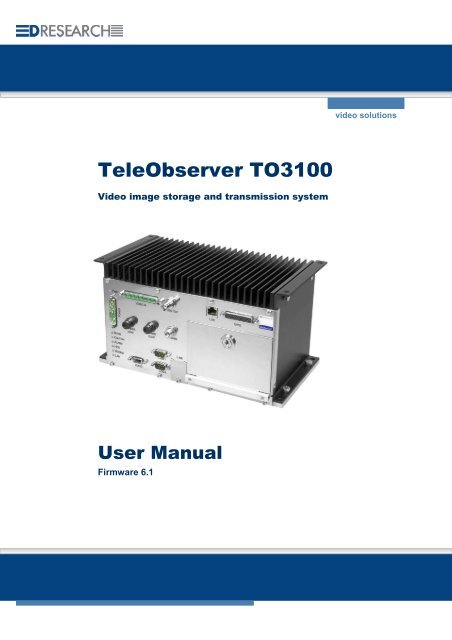
TeleObserver <strong>TO3100</strong><br />
Video image storage and transmission system<br />
User <strong>Manual</strong><br />
Firmware 6.1<br />
video solutions
<strong>DResearch</strong> – User manual TeleObserver <strong>TO3100</strong> 2011-02-03<br />
This document or parts thereof may not be copied, reproduced, abridged, translated or transmitted by<br />
any means whatsoever without the express permission of <strong>DResearch</strong>. <strong>DResearch</strong> has taken the<br />
greatest possible care in its production. <strong>DResearch</strong> shall not be responsible for the consequences of<br />
any typographical or transmission errors in relation to the user manual, which has only an informative<br />
character.<br />
<strong>DResearch</strong> reserves the right to make modifications to the content of the user manual at any time<br />
without an obligation to notify third parties of this. Any modification to this product or to the<br />
accompanying software that is not expressly approved by <strong>DResearch</strong> shall lead to the extinguishment<br />
of the operating license and of the warranty.<br />
All company and/or product names are trade names and/or protected trade names of the respective<br />
manufacturer.<br />
Copyright 2011 by <strong>DResearch</strong> (Germany)<br />
2
<strong>DResearch</strong> – User manual TeleObserver <strong>TO3100</strong> 2011-02-03<br />
C O N T E N T S<br />
1 <strong>DResearch</strong> system overview and general information about <strong>TO3100</strong> .................................... 5<br />
1.1 Systemübersicht und neue Funktionalitäten in dieser Version ............................................................. 6<br />
1.2 Scope of delivery.................................................................................................................................. 7<br />
1.3 Accessories & additional devices ......................................................................................................... 7<br />
1.4 Safety advice........................................................................................................................................ 8<br />
1.5 Warranty............................................................................................................................................... 9<br />
1.6 Certifications, standards and conformities............................................................................................ 9<br />
1.7 Scope of use ...................................................................................................................................... 10<br />
1.8 General installation information .......................................................................................................... 10<br />
1.9 Temperature range............................................................................................................................. 11<br />
1.10 System components and device features........................................................................................... 12<br />
2 The TeleObserver <strong>TO3100</strong> in detail ........................................................................................... 15<br />
2.1 Device description .............................................................................................................................. 15<br />
2.2 Changing and inserting the removable disk........................................................................................ 16<br />
2.3 Significance of the status LEDs.......................................................................................................... 17<br />
2.4 Significance of the status LEDs during software update..................................................................... 18<br />
2.5 Device interfaces................................................................................................................................ 19<br />
2.5.1 Analogue video inputs 1 ... 8 – Connection of analogue CCTV cameras ...................................... 19<br />
2.5.2 LAN Interface – Connection to the Ethernet .................................................................................. 19<br />
2.5.3 Video Out 1 - Control monitor connection...................................................................................... 20<br />
2.5.4 Power supply for the device and cameras ..................................................................................... 21<br />
2.5.5 COM 1 – Connection for serial data transmission.......................................................................... 22<br />
2.5.6 COM 2 Interface – External modem connection ............................................................................ 23<br />
2.5.7 Audio-Interface .............................................................................................................................. 23<br />
2.5.8 Digital I/O, RS485, IBIS, GPS, BMK .............................................................................................. 24<br />
2.5.9 Inserting the SIM Card at model <strong>TO3100</strong> GPRS ........................................................................... 28<br />
2.5.10 Connecting the GSM antenna........................................................................................................ 28<br />
2.5.11 Fuses............................................................................................................................................. 28<br />
3 Switching on the TeleObserver <strong>TO3100</strong> Device....................................................................... 29<br />
3.1 File system test of the hard disk during starting procedure ................................................................ 29<br />
4 The device service menu............................................................................................................ 30<br />
4.1 Service connection using serial interface COM1 (service cable)........................................................ 30<br />
4.2 Service connection using ethernet interface (X-link cable)................................................................. 30<br />
4.3 Service Login using telnet .................................................................................................................. 31<br />
4.4 The service menu function ................................................................................................................. 32<br />
4.5 Device access using the FTP-Server ................................................................................................. 33<br />
5 Device configuration with the Software CMS:: System Management ................................... 33<br />
5.1 SystemManagement – Module for device configuration..................................................................... 34<br />
5.2 CMS::SystemManagement - The device configuration....................................................................... 36<br />
5.2.1 System – Connections :: Modems ................................................................................................. 37<br />
5.2.2 System – Connections :: GPS ....................................................................................................... 39<br />
5.2.3 System – Connections :: Mobile IP................................................................................................ 40<br />
5.2.4 System – Connections :: VPN........................................................................................................ 41<br />
5.2.5 System :: Network.......................................................................................................................... 42<br />
5.2.6 System – Software :: Version......................................................................................................... 42<br />
5.2.7 System – Software :: Device address ............................................................................................ 43<br />
5.2.8 System – Software :: Holidays....................................................................................................... 43<br />
5.2.9 System – Software :: Time............................................................................................................. 44<br />
5.2.10 System – Software :: Event protocol.............................................................................................. 45<br />
5.2.11 System – Software :: Passwords ................................................................................................... 45<br />
5.2.12 Connections................................................................................................................................... 45<br />
5.2.13 Devices :: Cameras ....................................................................................................................... 46<br />
5.2.14 Devices :: Detectors....................................................................................................................... 47<br />
5.2.15 Devices :: Relay............................................................................................................................. 48<br />
5.2.16 Devices :: Audio............................................................................................................................. 49<br />
5.2.17 Database :: Drives ......................................................................................................................... 50<br />
3
<strong>DResearch</strong> – User manual TeleObserver <strong>TO3100</strong> 2011-02-03<br />
5.2.18 Database :: Archives...................................................................................................................... 51<br />
5.2.19 Hosts ............................................................................................................................................. 52<br />
5.2.20 Timer ............................................................................................................................................. 54<br />
5.2.21 Activations ..................................................................................................................................... 58<br />
5.2.22 Video Stream Profiles .................................................................................................................... 63<br />
5.2.23 Video Output.................................................................................................................................. 65<br />
6 Update & Reset, maintenance, problem analysis and technical support ............................. 67<br />
6.1 Update of the system.......................................................................................................................... 67<br />
6.2 Maintenance, cleaning and care of the system .................................................................................. 68<br />
6.3 Problem analysis and resolution......................................................................................................... 69<br />
6.4 Technical support by the manufacturer .............................................................................................. 70<br />
7 TeleObserver <strong>TO3100</strong> Specifications........................................................................................ 71<br />
8 Technical drawing ....................................................................................................................... 73<br />
9 Examples for system installation .............................................................................................. 76<br />
10 Abbreviations ..................................................................................................................... 78<br />
4
<strong>DResearch</strong> – User manual TeleObserver <strong>TO3100</strong> 2011-02-03<br />
1 <strong>DResearch</strong> system overview and general information about <strong>TO3100</strong><br />
Dear Customer, thank you for your purchase of this TeleObserver. We are sure you will be pleased<br />
with your decision. The <strong>TO3100</strong> mobile recording and evaluation system for video data is a compact<br />
system for recording and transmitting compressed video data. The system was designed specifically<br />
to meet the market’s special requirements for applications in the growing mobile video surveillance<br />
segment (temperature, vibration resistance, sturdiness), with compact external dimensions and a long<br />
operating life. It is available in two versions – the GSM type is using an internal modem for<br />
GSM/GPRS transmission, the DX version has no included modem but using an external device is<br />
possible.<br />
The system enables the encrypted recording of up to 8 video sources in high resolution (one field) on<br />
a removable hard disk. Via a communication connection it is possible to transmit live images from any<br />
selected camera or as a composite image from up to 4 cameras (Quadview). The system provides a<br />
large selection of interfaces for configuration, expansion, maintenance and integration into existing<br />
systems. The user manual is intended for project planners, system administrators and users who want<br />
to use the components of the system without any previous specialist knowledge. The manual will help<br />
you make efficient use of the <strong>TO3100</strong> system’s wide-ranging capabilities.<br />
Please take some time to read the user manual carefully so that you are familiar with the complete<br />
functional scope of the system and its application requirements. The documentation for the device is<br />
provided on the software CD supplied with the device.<br />
We wish you every success in working with the TeleObserver <strong>TO3100</strong>!<br />
<strong>DResearch</strong> systems at a glance MR3060* MR3140 MR3180 TO1200* <strong>TO3100</strong><br />
Recording analogue yes yes yes - yes<br />
Recording digital - yes yes - -<br />
Video-IN analogue (max.) 6 4 8 4 8<br />
Video-IN digital (max.) - 8 8 - -<br />
Video-OUT 1 2 2 - 1<br />
Transmission using SMS, Video (GSM,<br />
GPRS, EDGE) in case of alarms<br />
yes *** yes *** yes *** yes ** yes **<br />
Recording GPS-Daten yes yes yes yes yes **<br />
Recording IBIS-Daten yes yes yes - yes **<br />
max. capacity of storage disks (GB) 500 250 250 - 160<br />
Motion detection yes yes yes - -<br />
Sabotage detection yes yes yes - -<br />
Digital signature of data yes yes yes yes yes<br />
Digital Inputs 6 6 8 6 8<br />
Digital Outputs 4 4 2 4 6<br />
RS232/485 yes yes yes yes yes<br />
Video management software incl. yes yes yes yes yes<br />
* The system TO1200 is no longer available from 2010, the system MR3060 is available from 2010.<br />
** optional, depends on type of device and/or software module key<br />
*** only for SMS transmission via external device<br />
5
<strong>DResearch</strong> – User manual TeleObserver <strong>TO3100</strong> 2011-02-03<br />
1.1 Systemübersicht und neue Funktionalitäten in dieser Version<br />
Systemübersicht<br />
� Recording of video signals from up to 8 analogue CCTV cameras in separated archives<br />
(continuously recording and alarm recording)<br />
� Recording of video, audio and additional data (IBIS, GPS, logfiles)<br />
� Automatic deletion and overwrite protection of archives<br />
� Transmission of video and additional data using GPRS/UMTS 1<br />
� Recording formats CIF, + 2CIF – Encoding using H.263+<br />
� integrated OpenVPN client for use with DR.TONIC VPN server solution<br />
� Selftest of the unit and automatic securing of the data integrity<br />
� galvanisch getrennte Relaisausgänge zum Schalten von externen Geräten<br />
� Digital inputs for switches / buttons and alarm detectors<br />
� Digital relay outputs to switch external devices (galvanic isolation)<br />
� Operation mode: Standby, recording<br />
� Robust and fanless design, maintenance free, vandal safe<br />
� integrated heating system<br />
� Vehicle fit and certified in accordance to e1 (road), EN50155 (rail)<br />
and ‘Germanischer Lloyd’ (shipping)<br />
� Extensive configuration options<br />
� Ethernet Interfaces (RJ45), serial interface RS232, 485<br />
� Usable storage devices: HDD und SSD (S-ATA) with capacity from 80 to 160 GB<br />
� alarm notification, automatic transmission of live pictures to the alarm central station<br />
� Datensicherheit: Mehrstufiger Zugriffsschutz auf System und Daten<br />
� triggers for system faults and external events<br />
� And much more…<br />
A detailed overview of the possibilities of the system is given in this document and further<br />
information materials, like system description or application concepts from <strong>DResearch</strong> –<br />
request them or visit us on our website:<br />
www.<strong>DResearch</strong>.de<br />
New features in this firmware – version 6.1<br />
� Data analysis of storage devices with new analysis software Image Finder NX und the analysis<br />
station USB-TTU. (Requirement: the system which recorded the data is equipped with firmware<br />
version 6.x).<br />
� Integrated FTP server used for system update<br />
� Fleet update: several systems can be updated now with one update disk (will be shipped from<br />
manufacturer)<br />
� Swapping of storage devices using several videosystems: the storage devices of the systems<br />
<strong>TO3100</strong> can be used with MR-systems and reverse. Attention: the storage disk must have the<br />
same capacity!<br />
� Changes in standard benaviour: the system formats new inserted storage devices!<br />
� Changes in standard benaviour: the system will break the recording if an access to the video<br />
archives occurs (e.g. on analysis reasons)<br />
1 nur bei Modell <strong>TO3100</strong> GPRS verfügbar<br />
6
<strong>DResearch</strong> – User manual TeleObserver <strong>TO3100</strong> 2011-02-03<br />
1.2 Scope of delivery<br />
� <strong>TO3100</strong> recording device (preconfigured)<br />
� removable hard disk (capacity according to order)<br />
� Software for configuration and analysis (Central Monitoring Software - CMS)<br />
� Licences for the CMS<br />
� Product CD with software and documentation<br />
1.3 Accessories & additional devices<br />
The devices can be expanded with various accessories. For a detailed list of all the accessories<br />
offered by <strong>DResearch</strong>, please refer to the current product catalogue. For other information and<br />
ordering of accessories please contact your system integrator or our team direct.<br />
Assortment of additional devices for the system:<br />
� Power supply unit 24V/2,5A<br />
� Power – plug (ready-made 75cm cable with pin sleeves)<br />
� MO-bearing for vibration damped mounting<br />
� Mounting kit, video cabel Plugset<br />
� Service cable (Crosslink and patch cables, serial service cable)<br />
� Plug set GPIO, Plug set Ext. Device<br />
� DC/DC transformer (various input voltages, Out: 12-24V)<br />
� Removable hard disks in various capacities: 160 and 250 GB<br />
� Video- and network cables (CAT 5; 6 ) in various lengths<br />
� GPIO tester<br />
Assortment of additional devices to extend the system<br />
� WLAN module<br />
� Various versions of GPS receiver and GSM antenna<br />
� Modems for sending SMS<br />
� Rail media coupler<br />
� Various analogue cameras<br />
� Colour and b&w surveillance monitors for fitting into vehicles (trucks, buses, trams,<br />
trains)<br />
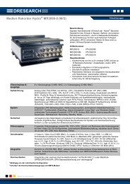
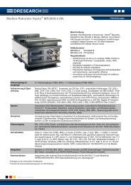
A complete installation in a rail carriage when expanded with accessories could look like this:*<br />
* This is an illustrative example. The <strong>TO3100</strong> supports recording of up to eight analogue CCTV cameras<br />
7
<strong>DResearch</strong> – User manual TeleObserver <strong>TO3100</strong> 2011-02-03<br />
1.4 Safety advice<br />
Incorrect handling can, at its worst, lead to personal injury or destruction of the device, and/or the<br />
termination of the guarantee. Therefore please be sure to note and follow the advice below before<br />
operating the device.<br />
� Never try to insert objects into any device openings since this could cause short-circuits or<br />
deliver electric shocks because of the voltage inside the unit.<br />
� Only use original parts or products recommended by the manufacturer in the operation of<br />
the equipment. If you have a problem please consult your system integrator.<br />
� Avoid installing equipment where it could be exposed to excessive smoke, dust, vibration,<br />
chemicals, moisture, heat, direct sunlight or electromagnetic fields. Such exposure can have<br />
a detrimental effect on the operation of the device and – in the worst case – can cause<br />
damage to the device.<br />
� Never operate the device in locations where there is a danger that water might penetrate the<br />
device.<br />
� When connecting up the device with the peripherals ensure that the cable is not under<br />
tension. Ensure all cables are installed properly.<br />
� Only remove the hard disk from the device when all the LEDs on the front panel are off. To<br />
remind you this warning is printed on the front of the removable hard disk.<br />
This is an (EMC) Class A system and can generate wireless interference in domestic<br />
environments.<br />
8
<strong>DResearch</strong> – User manual TeleObserver <strong>TO3100</strong> 2011-02-03<br />
1.5 Warranty<br />
The warranty terms for materials and manufacturing faults are, unless otherwise agreed by special<br />
negotiation, set out by <strong>DResearch</strong> Fahrzeugelektronik GmbH in its General Terms and Conditions.<br />
The General Terms and Conditions are to be found in the documents supplied. No further, expressed<br />
or tacit guarantees are accepted. The manufacturer is not responsible for claims arising from the<br />
improper handling or faulty installation by third parties.<br />
The warranty is terminated if repairs or interventions are made by people who have not been<br />
authorised by the manufacturer. Claims arising from the inappropriate use of the equipment, incorrect<br />
maintenance or the use of accessories not recommended by the manufacturer are not covered under<br />
the terms of the warranty.<br />
Opening the device inevitably leads to the cancellation of all existing guarantee cover, guaranteed<br />
rights and agreed warranties.<br />
The supplied software and installation pack presuppose a conflict-free operating system. Solving<br />
problems relating to this require detailed knowledge of the systems used or their complete<br />
reinstallation. The manufacturer makes no guarantees that programs or systems operated by the user<br />
will deliver the desired benefits.<br />
If a product is returned under the terms of the warranty this is always to be agreed in advance with the<br />
supplier, otherwise the return will not be processed. If returning an item, you will be given a returns<br />
number which is to be used throughout the procedure. The manufacturer takes no responsibility for<br />
damage or insurance during transit. Cash on delivery and ‘carriage forward’ shipments are not<br />
accepted.<br />
1.6 Certifications, standards and conformities<br />
The device is made to current safety and reliability standards (state: 09/2008) for use in a variety of<br />
environments. It was designed specially for use in trucks and locomotives and meets current<br />
requirements of various European standards.<br />
Certifications, standards and conformities:<br />
� CE compliant to EN55022 class A<br />
� RoHS conformity<br />
� Conformity to European rail standard EN50155<br />
� e1 certification from the German Federal Bureau of Motor Vehicles and Drivers (KBA)<br />
� German Lloyd (GL) for use in navigation/shipment<br />
� Conformity to European EMC guidelines<br />
� Vibration IEC 61373-9 and shock IEC 61373-10-5<br />
� Heat & fire resistance DIN 53438-2, DIN 5510-2, EN 45545-5<br />
� EN 50121-3-2, EN 60068-1, EN 55024, EN 61000-6-2, EN 60529, EN 60950-1<br />
9
<strong>DResearch</strong> – User manual TeleObserver <strong>TO3100</strong> 2011-02-03<br />
1.7 Scope of use<br />
Public transport sectors<br />
Trams, suburban railways, underground railways, buses, local and long distance trains and other vehicles<br />
Distribution, logistics and transport sectors<br />
Secure cash transport, transportation of hazardous loads, trailers and storage areas, high-bay warehousing and<br />
distribution centres, etc..<br />
Housing and construction industry<br />
Local properties, lifts and entrance halls as well as building sites.<br />
Industry and commerce<br />
Builders yards, industrial sites, waterworks and water treatment works, pumping stations, power stations,<br />
transformer substations, wind farms, geothermal power stations, retail branches, shopping centres, etc.<br />
Maritime - Offshore<br />
Locks, sea level measuring stations, oil drilling platforms, off-shore wind farms, etc.<br />
Private sector<br />
Holiday cottages, residential property, bungalows, boats, yachts, other vessels.<br />
Caravans, camper vans, etc.<br />
1.8 General installation information<br />
Power supply<br />
� The device must be plugged into a buffered power supply (UPS or unswitched supply/permanent<br />
positive).<br />
� Do NOT use the on board train power supply switch to turn the system on. Use the ignition.<br />
� Ensure that the device is wired up exactly as described in the manual.<br />
Ensure there is a constant power supply of 12-24 VDC. Temporary power outages will be tolerated<br />
by the device but they are always to be avoided and can lead to system failures and permanent<br />
damage to the equipment (e.g. from lack of proper vehicle battery maintenance).<br />
The UPS must be a device which has been recommended by the manufacturer and has valid<br />
certification for the application type.<br />
Any damage resulting from disregarding this advice will not be covered by any guarantee or<br />
warranty.<br />
Cable length between device and cameras<br />
Long connection paths between device and cameras have detrimental effects on the quality of the<br />
video signals. Select camera positions so that as much as possible of the area to be monitored can be<br />
covered with minimum cable lengths. Your system integrator will help you with the design of the<br />
system.<br />
10
<strong>DResearch</strong> – User manual TeleObserver <strong>TO3100</strong> 2011-02-03<br />
Ventilation and cooling<br />
Avoid installations where heat can build up. The equipment is designed to function without the need<br />
for a fault-prone fan, but adequate air circulation needs to be provided round the cooling fins.<br />
Mounting<br />
The device has 2 guide rails (with holes) on the top and bottom which take mounting screws. If at all<br />
possible, mount the device on a mounting plate which can also take the necessary additional<br />
components such as a transformer and connection block.<br />
The device must not be mounted with the hard disk drive aperture facing down! When fitting<br />
ensure that it is possible to change the removable hard disks easily!<br />
1.9 Temperature range<br />
Storage temp.: maximum + 70°C<br />
Operating temp.: 0°C to + 55°C (normal HDD)<br />
0°C to + 70°C (HT- HDD, SSD)<br />
Humidity: 10 … 90 % (not condensed)<br />
When using conventional data storage devices (HDD) the unit will automatically shut down when it<br />
reaches its temperature limit of + 55°C (for normal HDD) in order to protect the hard disk.<br />
When the temperature reduces to below this limit, the device will automatically switch back on.<br />
This temperature-dependent switching event is stored in a log file.<br />
11
<strong>DResearch</strong> – User manual TeleObserver <strong>TO3100</strong> 2011-02-03<br />
1.10 System components and device features<br />
The complete system consists of three different modules which communicate with each other via a<br />
proprietary software data protocol which is the same irrespective of the operating system.<br />
The device <strong>TO3100</strong><br />
� Data recording and storage of video streams with metadata according to the predetermined<br />
configuration<br />
� Storage on a removable hard disk, data transmission via GSM, GPRS, UMTS*<br />
� Function and configuration: see following chapter<br />
* via integrated or external modem, depending of device variant<br />
Service computer and analysis station<br />
Usually the review station is used for analysing the recorded data. A service laptop is often employed for<br />
installation, configuration and system maintenance. A standard commercial computer can be used.<br />
Currently <strong>DResearch</strong> offers two software packages:<br />
Central Management Software (CMS)<br />
with the modules Vision, ImageFinder and SystemManagement for<br />
� Visualisation of recorded data (video, add. data)<br />
� Searching recorded data according to freely configurable parameters (e.g. time, events etc.)<br />
� Display of live video sequences (incl. additional data)<br />
� Device configuration<br />
� Operating systems (OS) supported: Windows XP Prof. and Vista<br />
ImageFinderNX<br />
(as successor to the CMS module ImageFinder) for the research and analysis of the recorded<br />
data. Furthermore it’s possible to draw up backups of the video data from the devices.<br />
(OS: Windows XP Prof., Vista). Usable only in conjunction with the USB-TTU.<br />
The previous CMS module Image Finder has been discontinued by the manufacturer and<br />
is no longer in development! Take advantage of analyzing the data with USB TTU in<br />
conjunction with Image Finder NX!<br />
The evaluation station (USB-TTU)<br />
This separate device (USB-TTU) has the following uses:<br />
� takes the removable hard disk for the evaluation/analysis of data<br />
� formats the hard disk<br />
� activates removable hard disks and decodes data<br />
(while using encryption through DR.Secure)<br />
� displaying synchronous video images<br />
� analyses recorded data (video, audio, metadata, like IBIS and GPS)<br />
� creation of data backups<br />
� exporting video data, printing video images etc.<br />
(For a detailed description of the whole functionality have a look in the manual of the USB-<br />
TTU)<br />
12
<strong>DResearch</strong> – User manual TeleObserver <strong>TO3100</strong> 2011-02-03<br />
System specification – an overview<br />
� recording system for video, audio and metadata, designed for buses, trains, trams and other vehicles,<br />
certified to e1 and EN 50155<br />
� 8 x video-in analogue composite (BNC), 1 x video-out analogue composite (BNC) for analogue cameras,<br />
QuadView - Presentation & Signal forwarding<br />
� transmission of video-, audio-* and additional data via GSM/GPRS and integrated** or external** modem<br />
(communication: GSM,GPRS, EDGE, UMTS), compression H.263+<br />
� 2 channel audio recording (e.g. for the documentation of the driver communication)*<br />
� removable hard disk: up to 160 GB HDD, 64 GB SSD<br />
� recording of metadata such as IBIS (VDV 300), GPS, CAN-Bus optional<br />
� Interfaces: RS232, RS485, Ethernet, IBIS<br />
� 8 digital alarm inputs and 4 outputs for switch relays<br />
� Integrated power supply for 8 analogue cameras (12 V DC)<br />
� Compact, robust industrial design for use in the most difficult conditions with protection against vibration<br />
� Stable cast aluminium housing, maintenance-free through fan-free operation<br />
* audio recording is optional and only possible with 4-channel devices<br />
** GSM variant with, DX version without built-in mode<br />
Software and data management<br />
� Live video pictures, search and playback function and fast video download via an Ethernet-Interface<br />
� Configuration and management software with ergonomic graphical user interface<br />
� Expanded event and information management, including IBIS / GPS metadata<br />
� Support for alarm and fleet management<br />
� Data encryption, watermark, sabotage recognition, role-based access management, motion detection<br />
� Flash based LINUX operating system and hardware control system<br />
� H.263+ picture compression with recording rates up to 200 frames per second<br />
� SMS support for alarm events as well as for maintenance/service-support (GSM modem required)<br />
Detailed information you will find in this manual and the data sheet.<br />
13
<strong>DResearch</strong> – User manual TeleObserver <strong>TO3100</strong> 2011-02-03<br />
Feature Description<br />
Configurable video<br />
recording<br />
Configurable picture<br />
resolution (picture<br />
format)<br />
Configurable picture<br />
quality<br />
Configurable alarm<br />
recording<br />
Activated alarm<br />
recording display<br />
Configurable audio<br />
recording<br />
Configurable metadata<br />
recording<br />
Display of the event<br />
log<br />
The configuration has to be determined before recording begins!<br />
� Recording of video sequences from up to 8 cameras in automatic generated<br />
archives (one ring, alarm and pre-alarm archive per camera).<br />
� Maximum of 25 pictures/s for analogue cameras at the 8 video inputs<br />
� Definable setting for maximum age for the video footage.<br />
The picture format has to be determined before recording begins!<br />
� Recording formats from analogue cameras<br />
� CIF (352 x 288 = 101 376 Pixels)<br />
� Half frame/2CIF (704 x 288 = 202 752 Pixels)<br />
� For each analogue camera there are 5 different settings for the picture quality of<br />
the recorded video footage.<br />
� Pre- and post-alarm recording times are configurable.<br />
� Events can be used to start alarm recording.<br />
� Data recorded with this feature are marked as such. The alarm footage is not<br />
automatically overwritten.<br />
� The maximum age of the alarm sequences can be determined.<br />
� If alarm recording is activated, this is indicated by the yellow HD LED and it is<br />
displayed on the control monitor.<br />
� The recording of audio data is possible in three quality steps using two audio<br />
recording channels maximum.<br />
� Besides video footage, additional data such as date/time, camera name, IBIS<br />
and GPS data are recorded.<br />
� Information about the device is recorded in the event log. The log can analyzed<br />
with the analysis software<br />
System events � Show the various device and archive conditions<br />
Configurable,<br />
switchable video<br />
images using an<br />
external display<br />
� The live images of all cameras can be displayed at the system’s video output .<br />
� Switching to the live image from another camera is activated via an input (GPI) or a<br />
virtual detector.<br />
� Switching to the live image from another camera may be activated also via a timer<br />
controlled impulse.<br />
state information � LEDs show the device state.<br />
Logile � Device information can be entered in a log archive provided a user login is activated.<br />
Virtual state detectors<br />
Four video image<br />
display (Quadview)<br />
On Screen Display<br />
(OSD) information<br />
Transmission of a live<br />
video stream via data<br />
interface<br />
� Detectors that displays device and archive states. The virtual detectors can be used<br />
for activations and can be displayed in the video output.<br />
� The video output of the system displays at the same time the images of the video<br />
inputs 1– 4 on the screen.<br />
� The view can be activated using a switch connected to a digital input of the<br />
system<br />
� The time, date, camera name, detector number and virtual detector can be optionally<br />
displayed on the video output image of the <strong>TO3100</strong> system. Detectors must be<br />
defined before they can be configured to be shown in the image.<br />
� The position of the parameters is freely selectable.<br />
� The images will be transmitted live to the work station and displayed there.<br />
Furthermore, additional information (IBIS, GPS) and the current state of the<br />
detectors will be transmitted to the CMS.<br />
14
<strong>DResearch</strong> – User manual TeleObserver <strong>TO3100</strong> 2011-02-03<br />
2 The TeleObserver <strong>TO3100</strong> in detail<br />
2.1 Device description<br />
The <strong>TO3100</strong> is one part of the complete recording system and works without a fan. The housing is<br />
made from non-rusting, maintenance-free material. The data transmission and recording processes in<br />
the device are encrypted to prevent unauthorised access to the data. The file and security operating<br />
systems used prevent loss of important files if there is a power outage and therefore maintain<br />
continuity.<br />
Operation LED<br />
Power supply<br />
for external<br />
devices<br />
The device forms the switching centre and link between all other system components. It provides the<br />
interfaces for the connection of up to 8 analogue cameras, peripherals such as WLAN modem, GSM<br />
modem, PoE switch, driver monitor, relays and switches as well as other components:<br />
Front view of <strong>TO3100</strong><br />
System<br />
state LED<br />
display<br />
�<br />
The diagram shows a fully populated system. The system type <strong>TO3100</strong> GPRS uses an internal<br />
modem connected to COM2. Therefore, COM2 is not available as an external interface in this device<br />
type.<br />
Video In 1 .. 8<br />
Audio<br />
Fuse for system<br />
and external power supply<br />
Video Out<br />
RS 232<br />
(COM1, COM2)<br />
Antenna<br />
interface<br />
SIM<br />
Card holder<br />
Ethernet RJ45<br />
Digital I/O, RS 485,<br />
IBIS, GPS<br />
Lockable storage device slot<br />
15
<strong>DResearch</strong> – User manual TeleObserver <strong>TO3100</strong> 2011-02-03<br />
2.2 Changing and inserting the removable disk<br />
In <strong>TO3100</strong> devices use only the hard disks provided and pre-formated by <strong>DResearch</strong>. Only hard<br />
disks with the same capacity should be used within each fleet. For more information and for<br />
ordering hard disks please contact the sales team (E-Mail: sales@dresearch.de).<br />
Use only original hard disks from the manufacturer!<br />
Otherwise all existing warranties and guarantees are invalidated.<br />
To prevent any manipulation of the data, the hard disk is adopted by the device. This process happens<br />
when the device starts up with the hard disk for the first time. Only after this can recording start. To<br />
prepare the device for recording for the first time proceed as follows:<br />
� Switch the device off and wait until all the LEDs have gone out<br />
(by unlocking the HD lock) – this takes several seconds<br />
� Without using physical force carefully insert a formatted (!) removable hard disk (label upwards)<br />
in the carrier guides.<br />
� Lock the HD lock again - the system will start again.<br />
� The hard disk capacity will be automatically allocated to the camera archives by the software. No<br />
further intervention is necessary.<br />
� The device carries out an automatic restart of the system.<br />
The TO recorder series’ removable disk<br />
Please ask your system integrator or the<br />
manufacturer about the sizes and models<br />
currently available. (For older device models the<br />
disks are integrated in metal cages.)<br />
Only remove the hard disk when all the LEDs on the front of the device are off! Removing the<br />
hard disk before the LEDs go out results in damage to the device. All warranties and<br />
guarantees are thereby invalidated!<br />
When opening the door the device will be switched off automatically for security reasons.<br />
� If the capacity of the new hard disk is lower than defined in the current device configuration, the<br />
hard disk will not be accepted. Reduce the size of the existing archives BEFORE changing the<br />
hard disk.<br />
If an unknown storage drive is used with the system it will generally formatted at startup after a<br />
period of 60 seconds. If a cancellation of data to be desired, the system can be switched off in<br />
order to prevent the formatting process. Swapping storage drives between systems <strong>TO3100</strong> and<br />
MR systems is possible in principle - here, the media must, however, have the same capacity.<br />
CAUTION: The use of other media with a smaller capacity than the previous disc is not supported!<br />
For example: When it has been used a 160 GB disk, so no disk can then be used with a capacity of<br />
80 GB. By using higher-capacity disks archives in the system must be adjusted<br />
(CMS::System Management database ���� drives).<br />
16
<strong>DResearch</strong> – User manual TeleObserver <strong>TO3100</strong> 2011-02-03<br />
2.3 Significance of the status LEDs<br />
On the front of the unit there are six coloured LEDs which indicate the current status of the device. At<br />
any time you can determine the current status of the device from the colour codes. We recommend<br />
that you print out the following table and keep it with your service documents.<br />
LED State Description<br />
Mode<br />
Warning<br />
Alarm<br />
HDD<br />
Modem<br />
Ethernet<br />
off � Device is switched off<br />
green<br />
orange<br />
red<br />
� Device is ready for operation; „normal“ operation<br />
� Device is booting or shutting down; follow-up timeafter the<br />
disconnection of the ignition signal (Shut down)<br />
� Initialisation<br />
off � No warning<br />
orange � Violation of the limit value for the temperature<br />
red � Error<br />
off � No alarm<br />
red � Alarm active<br />
off � Device is not recording<br />
green � Standby; HD is ready for operation<br />
orange � File system check or<br />
� 60 second safety time before an unknown disk will be deleted<br />
red � Hard disk is not available or could not be recognised/adopted by the<br />
device.<br />
� No recording on the hard disk<br />
� other errors<br />
off � The modem is not ready for operation.<br />
green � Standby; the modem is ready for operation<br />
orange � no network (kein Modem vorhanden??)<br />
red � Error SIM card<br />
off � no Ethernet connection available<br />
green � Standby; Ethernet connection available<br />
The codes listed here could be changed by the manufacturer. If in doubt contact your system<br />
integrator or the manufacturer.<br />
17
<strong>DResearch</strong> – User manual TeleObserver <strong>TO3100</strong> 2011-02-03<br />
2.4 Significance of the status LEDs during software update<br />
During a software update, the LED blinking codes of the state display are different to the blinking<br />
codes of the normal operation. They shows the state and the progress of the software update.<br />
LED State Description<br />
Modus<br />
Warnung<br />
Alarm<br />
HDD<br />
Modem<br />
Ethernet<br />
fashing red � during the entire update<br />
fashing<br />
orange<br />
� during step 1<br />
green � finishing step 1<br />
fashing<br />
orange<br />
� during step 2<br />
green � finishing step 2<br />
fashing<br />
orange<br />
� during step 3<br />
green � finishing step 3<br />
flashing<br />
orange<br />
� during step 4<br />
green � finishing step 4<br />
flashing<br />
orange<br />
� during step 5<br />
green � finishing step 5<br />
The system will restart several times while processing the update – do not interrupt this<br />
process. During the process must be ensured a continuous supply of the system.<br />
18
<strong>DResearch</strong> – User manual TeleObserver <strong>TO3100</strong> 2011-02-03<br />
2.5 Device interfaces<br />
2.5.1 Analogue video inputs 1 ... 8 – Connection of analogue CCTV cameras<br />
Up to eight standard commercial CCTV cameras can be connected via the BNC connections<br />
IN 1 to IN 8 provided they have BNC connectors and deliver an analogue CCIR standard (CVBS,<br />
PAL/NTSC) signal. The operating voltage for the cameras is provided by the <strong>TO3100</strong> recorder itself<br />
(12V DC). Before video footage can be recorded from a camera, video recording for this camera has<br />
to be explicitly activated in the Central Monitoring Software (See configuration chapter).<br />
Note that you can only ensure a stable camera power supply of 12 V if the power supply to the<br />
recorder is always over 13V.<br />
The illustration below shows the 8-camera model. It is recommended to cover the video cable<br />
additionally with a ferrite core.<br />
Socket on the TeleObserver Standard accessories, Video In 8 plug set<br />
2.5.2 LAN Interface – Connection to the Ethernet<br />
Pin Name Description<br />
1 Tx+ Transceive Data+<br />
2 Tx- Transceive Data-<br />
3 Rx+ Receive Data+<br />
4 Not used<br />
5 Not used<br />
6 Rx- Receive Data-<br />
7 Not used<br />
8 Not used<br />
This interface supports a bandwidth of 100 Mbit.<br />
Using the RJ45-interface (LAN, Ethernet) and a patch cable (CAT 5 or higher) you can connect the<br />
device with other external devices. This might be:<br />
A computer - for configuration and/or control through the CMS<br />
External devices - such as a WLAN-modem, switches<br />
Only use <strong>DResearch</strong> recommended accessories!<br />
19
<strong>DResearch</strong> – User manual TeleObserver <strong>TO3100</strong> 2011-02-03<br />
2.5.3 Video Out 1 - Control monitor connection<br />
Use the video output (BNC, analogue composite) to connect an external video monitor. In case of<br />
necessary to use more than one monitor, the use of a video switch is required. In this case the video<br />
signal will duplicated to the scond monitor.<br />
2.5.3.1 Sequential video output and quad view<br />
Using a switch connected to a digital input allows switching the video signals from each camera<br />
showing the signal at an external monitor.<br />
Use the configuration swoftware module CMS::System management ���� activations to configure the<br />
switch and the video output actions. With the external switch it is possible to switch the video signals<br />
of all 8 video inputs and display them at the monitor. In mode Quadview only the representation of the<br />
camera signal is 1 .. 4 is possible.<br />
We offer a variety of monitors on-our sales staff will gladly inform you about our current products.<br />
2.5.3.2 Display of information and system events (OSD)<br />
Several information such as camera name, date, time and other can be displayed using the On<br />
Screen Display (OSD) Feature. To use this option switch on the function and set the appropriate<br />
settings in the system configuration (CMS::System management ���� video output).<br />
20
<strong>DResearch</strong> – User manual TeleObserver <strong>TO3100</strong> 2011-02-03<br />
2.5.4 Power supply for the device and cameras<br />
Connect the constant vehicle power supply to the appropriate power supply pins of the device (pins<br />
A2, A3 - power range: +18VDC … +36 VDC). The device is switched on and off via a connection<br />
through the vehicle’s ignition switch. For this, the car ignition or the mode selection switch must be<br />
connected to the +24 V input (connectors 3 and 4) of the TeleObserver. The system can now be<br />
automatically switched on and off, according to the state of the vehicle.<br />
The interface provides power for the device itself and makes supply voltage available for further<br />
external devices (12V DC; e.g. analogue cameras).<br />
Interface Pin Name Description<br />
A4<br />
A3<br />
A2<br />
A1<br />
2<br />
1<br />
5<br />
4<br />
3<br />
A1 Camera_POWER(+12V DC) + camera power supply<br />
A2 POWER_IN (24 V DC) + power supply<br />
A3 GND - power supply<br />
A4 Camera_GND - camera power supply<br />
1 -<br />
2 -<br />
3 Input1+ Ignition, high, 24 V DC, galvanically<br />
separated (optocoupler)<br />
4 Input1- Ignition, low, 24 V DC, galvanically<br />
separated (optocoupler)<br />
5 -<br />
Ensure there is a constant power supply of 18 - 36 VDC on Pin A2. Temporary power outages<br />
(e.g. from lack of proper vehicle battery maintenance) will be tolerated by the device but they are<br />
always to be avoided and can lead to system failures and permanent damage to the equipment.<br />
The UPS must be a device which has been recommended by the manufacturer and has valid<br />
certification for the application type. Any damage resulting from disregarding this advice will not<br />
be covered by any guarantee or warranty.<br />
21
<strong>DResearch</strong> – User manual TeleObserver <strong>TO3100</strong> 2011-02-03<br />
Example showing connection of device and cameras<br />
+12V/+24V<br />
GND<br />
2.5.5 COM 1 – Connection for serial data transmission<br />
The COM1 port (RS232) on the front of the recorder is used (as a service interface) for maintenance<br />
of the device or for connecting external devices such as a GPS receiver or modem.<br />
The interface (D-SUB 9, male) is configured as standard for RS232:<br />
Interface Pin Name Description<br />
(male)<br />
+12V<br />
GPS receiver connection<br />
1 CD Carrier Detect<br />
2 RxD Receive Data<br />
3 TxD Transmit Data<br />
4 DTR Data Terminal Ready<br />
5 GND System Ground<br />
6 DSR Data Set Ready<br />
7 RTS Request to Send<br />
8 CTS Clear to Send<br />
9 RI Ring Indicator<br />
Note that the only navigation systems and GPS receivers supported are those recommended by<br />
<strong>DResearch</strong>. The GPS receiver can be connected directly to the COM1 port. The port parameters can<br />
be configured in SystemManagement ���� GPS. (See Chapter 3, Configuration)<br />
Use as service interface<br />
Zündung<br />
Ignition<br />
High<br />
PIN3<br />
Side<br />
(HIGH)<br />
– PIN3<br />
Zündung Low Side – PIN4<br />
Ignition PIN4 (LOW)<br />
USV<br />
USV oder<br />
constant<br />
Dauerplus<br />
power<br />
Power<br />
The device will be switched on when a high<br />
power level is at Pin 3 "Ignition High Side"<br />
(min. 6 V). PIN 4 has to be connected to<br />
the return potential (ground).<br />
The service interface allows analysis of the device using a terminal. This should only be carried out by<br />
authorised experts. This requires the use of a fully wired serial service cable from <strong>DResearch</strong>.<br />
22
<strong>DResearch</strong> – User manual TeleObserver <strong>TO3100</strong> 2011-02-03<br />
2.5.6 COM 2 Interface – External modem connection<br />
If the device is working with an integrated modem (model GPRS), you can´t use the serial interface<br />
COM 2 as external interface due to the fact that is used for the internal modem unit.<br />
An external modem for sending SMS messages can be connected via the COM2 (RS232) port. This is<br />
automatically recognised by the recorder. The only modems which are supported are these ones<br />
available as accessory. A connected modem is automatically recognised by the recorder. An SMS-<br />
capable software receiver must be installed on your PC. This is not included in the shipment!<br />
When operating a GSM modem for the first time the access to the relevant providers has to be<br />
configured (PIN, AT commands etc.) before inserting the SIM card and connecting the modem to<br />
the <strong>TO3100</strong>.<br />
Incorrect operation can lead to the SIM card being blocked! <strong>DResearch</strong> takes no responsibility for<br />
the costs associated with a blocked SIM card if the above instructions are ignored and the<br />
equipment is operated improperly!<br />
2.5.7 Audio-Interface<br />
Use the audio adapter cable which is provided in the accessories to connect external audio devices to<br />
the recorder. Please note that the audio feature is only supported for 4-camera-systems. The audio<br />
functionality must be released.The interface (D-SUB 9, female) is wired as follows:<br />
(male)<br />
Pin Name Description<br />
1 Shield Connector for shielding<br />
2 AudioOut2+ Audio output 2 (positive)<br />
3 AudioOut1+ Audio output 1 (positive)<br />
4 AudioIn2+ Audio input 2 (positive)<br />
5 AudioIn1+ Audio input 1 (positive)<br />
6 AudioOut2- Audio output 2 (negative)<br />
7 AudioOut1- Audio output 1 (negative)<br />
8 AudioIn2- Audio input 2 (negative)<br />
9 AudioIn1- Audio input 1 (negative)<br />
23
<strong>DResearch</strong> – User manual TeleObserver <strong>TO3100</strong> 2011-02-03<br />
2.5.8 Digital I/O, RS485, IBIS, GPS, BMK<br />
The HDSub 44 (female) socket offers connectors of alarm notifiers, the RS485 serial interface and to<br />
establish a connection to your IBIS bus (Integrated On-board Information System), BMK (Rail Media<br />
Multilink system) or GPS receiver. Please note that only GPS receivers and navigation systems<br />
distributed by <strong>DResearch</strong> are supported.<br />
Connect the GPIO (30 pin) VZGPIO plug set to this socket. The connector offers up to 8 sensor<br />
(optical coupler input) connections. Furthermore, 4 switch outputs are available (2 x relay, 1 x high-<br />
side switch, 1 x optical coupler output). The optional GPIO (44 pin) VZGPIOALL plug set allows you to<br />
use the IBIS and RS485 serial interfaces. Alternately, you can connect the GPIO tester (available on<br />
request) to this socket.<br />
Interface Accessories<br />
Pin Code Description Pin Code Description<br />
1 (WBSD – vehicle<br />
bus transmitter<br />
data)<br />
GPIO (44 pins) plug set<br />
IBIS (signal transmitter) 23 OUT4-NO Relay: normally open<br />
2 Not used 24 OUT4-NC Relay: normally closed<br />
3 (RS485DB) RS485 (B) 25 I0- Input 0 (negative)<br />
4 OUT1-POWER High-side switch: Power 26 I0+ Input 0 (positive)<br />
5 OUT2+ Electronic make contact (high-side) 27 I3- Input 3 (negative)<br />
6 OUT3-NO Relay: make contact 28 I3+ Input 3 (positive)<br />
7 OUT3-NC Relay: break contact 29 I6- Input 6 (negative)<br />
8 OUT4-COMMON Relay: common contact 30 I6+ Input 6 (positive)<br />
9 Not used 31 (WBME –<br />
vehicle bus<br />
ground<br />
receiver)<br />
connector (rear view)<br />
D-SUB (44 pins)<br />
10 I1- Input 1 (negative) 32 Not used<br />
11 I1+ Input 1 (positive) 33 Not used<br />
IBIS (ground receiver)<br />
12 I4- Input 4 (negative) 34 OUT1-GND High-side switch: ground<br />
13 I4+ Input 4 (positive) 35 Not used<br />
24
<strong>DResearch</strong> – User manual TeleObserver <strong>TO3100</strong> 2011-02-03<br />
14 I7- Input 7 (negative) 36 Not used<br />
15 I7+ Input 7 (positive) 37 Not used<br />
16 (WBMS – vehicle<br />
bus ground<br />
transmitter)<br />
17 (WBED – vehicle<br />
bus receiver<br />
data)<br />
IBIS (ground transmitter) 38 Not used<br />
IBIS (signal receiver) 39 Not used<br />
18 (RS485DA) RS485 (A) 40 Not in use<br />
19 Not used 41 I2- Input 2 (negative)<br />
20 OUT1 High-side switch: output 42 I2+ Input 2 (positive)<br />
21 OUT2- Electronic make contact (low-side) 43 I5- Input 5 (negative)<br />
22 OUT3-COMMON Relay: common contact 44 I5+ Input 5 (positive)<br />
2.5.8.1 Digital I/O – Connecting Alarm Notifiers<br />
You can connect alarm notifiers via the digital inputs. The device has 8 general purpose inputs (the ‘I’<br />
in GPIO) and 4 general purpose outputs (the ‘O’ in GPIO). The connectors' pin assignments are<br />
illustrated in the table above. Each of the 8 (x = 0...7) inputs is electrically isolated via an optical<br />
coupler. The illustration shows a schematic diagram of an input circuit.<br />
2.5.8.2 High-side switch – Output OUT1<br />
Output OUT1 is a high-side switch output for switching external devices:<br />
25
<strong>DResearch</strong> – User manual TeleObserver <strong>TO3100</strong> 2011-02-03<br />
2.5.8.3 Electronic Make Contact – Output OUT2<br />
You can connect this output in the two different ways shown. Optionally (on request) they are<br />
electrically isolated and can supply an output cycle.<br />
Variant 1 Variant 2<br />
2.5.8.4 Relay Outputs OUT3 and OUT4<br />
Two outputs are relay outputs for switching external devices.<br />
2.5.8.5<br />
26
<strong>DResearch</strong> – User manual TeleObserver <strong>TO3100</strong> 2011-02-03<br />
2.5.8.6 GPIO Tester (optional)<br />
The optional GPIO tester (available as accessory) is connected to the TeleObserver´s digital I/O using<br />
the digital I/O cable. The power cable (with 230 V AC / 15 V DC adapter) must be connected to the<br />
connector "Power".<br />
� The 4 outputs show the status of the relays.<br />
� The LED ON indicates that voltage is present in the GPIO tester.<br />
� The 6 toggle switches are ON when flipped to the position Function.<br />
When the system starts, they must all be OFF (position "Input").<br />
� Use the RJ45 female connectors to connect the GPS adapter cable or the IBIS adapter cable.<br />
LED - Outputs<br />
The GPIO Tester indicates, with its 4 red LED outputs, the state of the relays (open/closed).<br />
The relays can be connected to the <strong>TO3100</strong> over the digital I/O. The relays are administered through<br />
the function Relays, in the SystemManagement. The manual switch can be made over the menu item<br />
Relays in Vision or over the relay icons in the Vision tree structure.<br />
Switches<br />
With the switches 01 to 08 in the GPIO Tester it is possible to react specifically to different events.<br />
The switches 06 and 07 can be used as toggle switch or as push-button. The switches are<br />
administered through the function Detector in the SystemManagement.<br />
The assignment of processes and actions (e.g. Shutdown or Transfer video output) to the different<br />
switches is done through the function Activations in the CMS::SystemManagement.<br />
27
<strong>DResearch</strong> – User manual TeleObserver <strong>TO3100</strong> 2011-02-03<br />
2.5.8.7 RS485 – Connecting Serial Interfaces<br />
Connect the integrated On-board Information System (IBIS) with the optional GPIO (44 pin)<br />
VZGPIOALL plug set to the digital I/O, RS485, or IBIS socket. The pin assignment of the socket is<br />
shown in the table at the beginning of this chapter.<br />
2.5.9 Inserting the SIM Card at model <strong>TO3100</strong> GPRS<br />
The model <strong>TO3100</strong> GPRS offers a SIM Card interface which is protected by a cover at the front side<br />
of the system. Remove this cover and insert the SIM card showing pins downside. To remove the SIM<br />
card push with a tool (e.g. a pen) at the ejector.<br />
2.5.10 Connecting the GSM antenna<br />
To operate the system <strong>TO3100</strong> GPRS with the internal modem, connect a suitable antenna to this<br />
port. Matching antennas you can purchase directly from the manufacturer or the system integrator.<br />
2.5.11 Fuses<br />
The TeleObserver <strong>TO3100</strong> device is equipped with a precision device fuse (6.3 AT) for the power<br />
supply input (main fuse) and a precision device fuse (4.0 AT) for the camera power supply (camera<br />
fuse).<br />
28
<strong>DResearch</strong> – User manual TeleObserver <strong>TO3100</strong> 2011-02-03<br />
3 Switching on the TeleObserver <strong>TO3100</strong> Device<br />
Before switching on the device, check that the voltage is connected with the correct polarity and<br />
amplitude (+18 V DC to +36 V DC). Connect the power supply plug to the voltage source. If using an<br />
optional GPIO tester, plug the power cable (with 230 V AC/ 15 V DC adapter) into an earthed 3-pin<br />
socket.<br />
Do not switch of the device when it is in the initialization phase (LED1 = red).<br />
The system automatically switches into the power-off status when you open the flap for<br />
removing the hard disk, using the key. This is to protect the hard disk when being removed while<br />
the power is unintentionally on.<br />
The entire TeleObserver <strong>TO3100</strong> device automatically switches off at temperatures above +55 °C<br />
(131 °F) (or +70°C (158 °F) when using a special HD ) and below –15 °C (5 °F).<br />
3.1 File system test of the hard disk during starting procedure<br />
Once the system is started, an automatically file system test is performed on the hard disk.<br />
File system OK<br />
Approximately 20 seconds after start, a green light in the LED-HDD indicates that the hard disk has<br />
been recognized and the file system is OK. The hard disk is ready for recording data.<br />
File system is defective<br />
Approximately 20 seconds after start, a red light in the LED-HDD indicates that the file system is<br />
defective. The device automatically starts the file system test during which it will be tried to repair the<br />
bad sectors.<br />
While the test is running, the LED-HDD will shine orange. The test can take long if the damage is<br />
serious. During this time no data can be recorded. The configuration of the device and live<br />
connections with the software module "Vision" continue to be possible.<br />
Once the test is finished and the damage is repaired, the LED-HDD shines again green, the<br />
TeleObserver device restarts and is then ready for recording data. If the LED-HDD shines red after<br />
the test is finished, it means the damage could not be repaired. In this case disconnect the device,<br />
change the hard disk and contact your distributor.<br />
29
<strong>DResearch</strong> – User manual TeleObserver <strong>TO3100</strong> 2011-02-03<br />
4 The device service menu<br />
Ask your administrator before undertaking changes in the network configuration of the device or<br />
the local computer.<br />
If you want to operate the system in a network environment or with a Laptop through the Ethernet<br />
interface it may be necessary to adapt the device to a specified network structure. Changes of the<br />
network settings are performed by using the internal service menu of the system. There are two<br />
possibilities to configure the IP-address:<br />
4.1 Service connection using serial interface COM1 (service cable)<br />
� Connect the PC or the Laptop to the COM1 interface of the <strong>TO3100</strong> device by using the<br />
service cable (<strong>TO3100</strong> accessory).<br />
� Start the program Hyperterminal (Start / Programs / Accessories / Communication …) or<br />
another terminal program. Establish a connection to the COM interface of your PC where the<br />
service cable is connected.<br />
� Click ENTER. If the settings are correct, a LOGIN prompt appears.<br />
Insert service and click ENTER.<br />
Further steps are stated below.<br />
4.2 Service connection using ethernet interface (X-link cable)<br />
The system is preconfigured in its delivery status and has an IP-address and a network address. The<br />
The factoy default IP-address is noted down in the delivery note and inside of the flap of the hard disk<br />
drive. Please mention that the service computer and the <strong>TO3100</strong> system must have IP-addresses into<br />
the same network segment.<br />
30
<strong>DResearch</strong> – User manual TeleObserver <strong>TO3100</strong> 2011-02-03<br />
4.3 Service Login using telnet<br />
Carry out the following steps to establish a connection to the service menu via Ethernet:<br />
� Establish a network connection between the PC and the video system using an Ethernet cable<br />
(PC and system must have IP addresses within the same network segment)<br />
� Start a commando promt shell and connect to the device using Telnet: telnet 10.32.x.x, after that<br />
the LOGIN prompt appears<br />
� Use service as login – if an access password is set the device will ask you for that<br />
� The selection menu opens – note: the service menu is only available in german language.<br />
31
<strong>DResearch</strong> – User manual TeleObserver <strong>TO3100</strong> 2011-02-03<br />
4.4 The service menu function<br />
The service menu offers different system functions:<br />
Function Description<br />
info Display of system information as serial number of the system, firmware<br />
version etc.<br />
network Configuration of network interface. Set here the IP-adress of the system<br />
and the gateway<br />
pwservice Set here the password to access the service menu<br />
pwftp Set here the password to access the FTP server (Update)<br />
registry Use that option to reset the registry<br />
restart Restart the system<br />
logout Logout from service menu<br />
32
<strong>DResearch</strong> – User manual TeleObserver <strong>TO3100</strong> 2011-02-03<br />
4.5 Device access using the FTP-Server<br />
The system provides a direct access to the update directory. This directory can be used as transfer<br />
directory (for exchange) and to perform firmware updates. The path to the directory is:<br />
ftp://10.32.xy/update<br />
By entering the respective IP-address of the system in conjunction with the path to the update<br />
directory is the possibility of the reader access. Write access is not possible using a browser<br />
application. Make this either a network ressource or use a FTP software.<br />
The FTP server is availabe using the user remote and a password which is set in the<br />
system settings.<br />
5 Device configuration with the Software CMS:: System Management<br />
Note: Use always the actual version of the configuration software. Before a connection to the<br />
system can established a HOST with the appropriate IP-address must be created.<br />
Module of the CMS software:<br />
� <strong>DResearch</strong> Vision – Receiving of live pictures und active alarm management<br />
� <strong>DResearch</strong> ImageFinder – analysis of recorded data of the video system<br />
� <strong>DResearch</strong> SystemManagement - configuration of the system<br />
� Extended – program specific settings<br />
�<br />
The CMS consists of the modules Vision,<br />
ImageFinder and SystemManagement. Only the<br />
system management module is relevant for the<br />
configuration of the recorder. There is a detailed<br />
description of the CMS software in the software<br />
manual.<br />
At the following pages only the module CMS::SystemManagement will described.<br />
Configuration should only be conducted by the manufacturer’s authorised specialist. The<br />
manufacturer accepts no liability or responsibility if damage results from improper treatment or<br />
incorrect settings.<br />
33
<strong>DResearch</strong> – User manual TeleObserver <strong>TO3100</strong> 2011-02-03<br />
Establishing of a connection between computer and videosystem:<br />
� Start the software CMS and afterwards the module CMS::SystemManagement<br />
� Create a remote station by whatever name and configure the IP address of the system on which<br />
the connection should be established (CMS::SystemManagement ���� Host).<br />
� Load the system configuration using the button � Connect<br />
� After successfully established connection the configuration is loaded and ready for customizing<br />
Function bar<br />
5.1 SystemManagement – Module for device configuration<br />
The individual functions are activated depending on the function call-up of the selection window.<br />
Menu and description<br />
Save � Saves the setting local on the PC, not on the device.<br />
Undo � Currently selected changes are discarded.<br />
Initializing � System is re-initialised.<br />
Connect<br />
Reject<br />
Transmitting<br />
� Communications unit is re-started.<br />
� Opens the Connection dialogue box in which the device is selected and whose<br />
configuration is to be loaded. After selecting and setting up the connection to the<br />
device the configuration is loaded.<br />
� Button is active when the recorder configuration is loaded.<br />
� Any configuration changes which have just been made are discarded and the device<br />
configuration menu is closed.<br />
� Current configuration changes are transmitted to the device, the configuration menu is<br />
closed and the device starts with new settings.<br />
New � Activates the entry fields.<br />
Delete � Deletes a selected element<br />
Info...<br />
� Is activated with the New button.<br />
� Activates a window with the current version number.<br />
34
<strong>DResearch</strong> – User manual TeleObserver <strong>TO3100</strong> 2011-02-03<br />
The main menu<br />
File<br />
Save � Saves all current changes.<br />
The functions File, Connection, Edit, View and Info (?) are<br />
available in the SystemManagement main menu.<br />
� Only effective after system is initialised (menu option Initialising)<br />
Cancel � Cancels the current procedure.<br />
Initialising � Re-initialises the system<br />
Save as � Saves the configuration.<br />
� First give the outstation a name.<br />
Open � Opens a saved configuration (choose from directory)<br />
� For security reasons saved configurations from other <strong>TO3100</strong> devices cannot be<br />
opened and transmitted.<br />
Close � Closes SystemManagement.<br />
Connection<br />
Receive settings � Sets up a connection to the <strong>TO3100</strong> and receives the settings from an outstation.<br />
� The dialog Connection will be opened.<br />
Discard settings � Is active if the device´s configuration menu is loaded.<br />
� Current configuration amendments are discarded and the device configuration menu is<br />
closed.<br />
Send settings � Sets up a connection to the <strong>TO3100</strong> and sends the amended settings to the device.<br />
Then the device starts with the new settings.<br />
Edit<br />
Before establishing a connection with the outstation (TeleObserver <strong>TO3100</strong> device) check<br />
whether this is also in operation. If the device is not available an appropriate error message<br />
will be shown.<br />
In this case the device is either switched off, the connection to the device is broken (cable) or<br />
the network settings are not correct.<br />
Undo � Undoes the new changes made.<br />
New � Activates the entry fields.<br />
Delete � Deletes a selected element.<br />
View<br />
� Is activated with the New button.<br />
Tooltips � Switches on and off the brief help tips which appear when the mouse rests on individual<br />
dialog fields.<br />
?<br />
Info about � Activates a window with the current version number and copyright details (equivalent of<br />
the Info button in the function bar).<br />
35
<strong>DResearch</strong> – User manual TeleObserver <strong>TO3100</strong> 2011-02-03<br />
5.2 CMS::SystemManagement - The device configuration<br />
Configuration of the device<br />
System - Connections<br />
The device configuration is loaded via<br />
CMS::SystemManagement ���� Receive.<br />
After selecting the particular device the<br />
configuration data is displayed in tree form.<br />
By selecting the individual entries on the left, the<br />
relevant dialogue box opens (on the right).<br />
The individual dialogue fields with the parameters<br />
and their significance are described in detail<br />
below.<br />
Modems � Configuration of modem settings and interface parameters<br />
GPS � Configuration of GPS properties and the interface parameters<br />
Mobile IP � Configuration of the GPRS access data<br />
VPN � Opens the dialog to configure the access data for the VPN server<br />
System – Network<br />
Network � Configuration of network address and gateway<br />
System - Software<br />
Version � Displays the serial number and hard and software version for the <strong>TO3100</strong><br />
Device address � Opens the "Device address" dialog<br />
Holidays � Opens the "Holidays" dialog<br />
Time � Select the time zone and the time synchronisation process.<br />
Event protocol � Opens a dialog to define system events which are to be logged in the log file<br />
Licence/Releases � Opens the "Licence/Releases" dialog<br />
Passwords � Entry or change:<br />
� the passwords for remote configuration and hard disk access<br />
� the access codes for the <strong>TO3100</strong>.<br />
Connections � Shows all inputs and outputs on the device.<br />
36
<strong>DResearch</strong> – User manual TeleObserver <strong>TO3100</strong> 2011-02-03<br />
Devices<br />
Cameras � Can set general camera settings (video standard, picture rate) and specific<br />
camera settings (activation of video recording, motion detection and sabotage<br />
detection, quality, resolution, brightness, contrast, colour saturation).<br />
Detector � Selection of detector type and actions which are to be carried out when the<br />
detector is triggered.<br />
� Can activate RMC detectors<br />
Relay � All relays are shown<br />
Audio � Settings for audio recording<br />
Database � Here you assign drives to the database and set up the archives.<br />
Drives � Opens the "Drives" window<br />
Archives � Here you define the archives (name, size etc.).<br />
Hosts � Opens the dialog to configure the hosts<br />
Timer � Opens the timer configuration dialog<br />
Activations � Opens the "Activations" dialog<br />
Video stream profile � Opens the configuration dialog for the camera video stream profiles<br />
Video output � Opens the dialog to configure the video output<br />
5.2.1 System – Connections :: Modems<br />
This dialog shows the parameters for the modems that are connected to the device. This function<br />
allows you to define new modems that are connected to the TeleObserver or modify existing<br />
configurations. The modem settings cannot be changed in devices with internal modems (<strong>TO3100</strong><br />
GPRS). In this case the fields are disabled. In the tree structure in the main window, select the Modem<br />
entry. The following dialog appears on the right-hand side of the main window.<br />
If you want to define the parameters for a<br />
new modem, then in the Edit menu, select<br />
New.<br />
37
<strong>DResearch</strong> – User manual TeleObserver <strong>TO3100</strong> 2011-02-03<br />
Feature Description<br />
List of defined modems � This list shows all previously configured modems.<br />
� If you click a modem in the list the parameters for this will be shown.<br />
Name � Shows the name of the modem that is selected in the list of defined modems.<br />
Modem type � Shows the type of the defined modem.<br />
Device � Shows which interface of device the modem is connected to.<br />
Port settings -<br />
� <strong>TO3100</strong> GSM: The already integrated modem is connected to the COM2<br />
interface.<br />
Bit rate � Shows the maximum bit rate that can be used for transmission between the<br />
modem and the COM port on the <strong>TO3100</strong> device.<br />
Data bits � Number of bits that are transferred in a data packet.<br />
Parity � Shows whether error checking is carried out or not.<br />
Stop bits � Number of stop bits between two transferred data packets.<br />
Flow control � Shows how the data flow between the serial interface and the modem is<br />
controlled.<br />
GSM � This field is only available when the GSM modem entry is selected in the<br />
"Modem type" field.<br />
PIN code � This field contains the PIN code for the SIM card in the connected GSM modem.<br />
HSCSD � The feature HSCSD is no longer provided<br />
ISDN � The feature ISDN is no longer provided<br />
Initialization � This field is only available when the "POTS modem" or "GSM modem" entry is<br />
selected in the "Modem type" field.<br />
Initialization � Shows the AT command that is used to initialise the modem.<br />
Dial prefix � Shows the number needed to get an outside line when the selected connection<br />
is on an extension.<br />
Dial delay � Shows the time that needs to elapse after hanging up before redialling is<br />
possible.<br />
38
<strong>DResearch</strong> – User manual TeleObserver <strong>TO3100</strong> 2011-02-03<br />
5.2.2 System – Connections :: GPS<br />
This function allows you to define new GPS devices that are connected to the <strong>TO3100</strong> device or<br />
modify existing configurations. In the tree structure in the main window, select the Connections- GPS<br />
entry. The following dialog appears on the right-hand side of the main window.<br />
Note: GPS data can be recorded if the activation "Record GPS data" is configured and active.<br />
Field Description<br />
Interface � Select the interface of the TeleObserver <strong>TO3100</strong> device on which the GPS<br />
device is connected.<br />
Bit rate � Shows the maximum bit rate that can be used for transmission between the GPS<br />
device and the COM port on device.<br />
Data bits � Number of bits that are transferred in a data packet.<br />
Parity � Shows whether error checking is carried out or not.<br />
Stop bits � Number of stop bits between two transferred data packets.<br />
Flow control � Shows how the data flow between the serial interface and the modem is<br />
controlled.<br />
GPS -<br />
Protocol � Select the protocol used by the GPS device.<br />
� Only the protocols "NMEA" is supported.<br />
Use following data sets � Highlight the corresponding check boxes to record GPS parameters.<br />
In software module Vision, the parameters may be displayed in the video image.<br />
39
<strong>DResearch</strong> – User manual TeleObserver <strong>TO3100</strong> 2011-02-03<br />
5.2.3 System – Connections :: Mobile IP<br />
This function allows you to define the GPRS access data of the TeleObserver <strong>TO3100</strong>. If you have<br />
questions or problems with the GPRS configuration, please contact your network operator or service<br />
provider. The connection between the TeleObserver device and the workstation may be established<br />
either via the VPN server or directly. In the tree structure in the main window, select the Mobile IP<br />
entry. The following dialog appears.<br />
Field Description<br />
Access data -<br />
Dial-in � Activate the check box if the connection is to be established via the GPRS<br />
network.<br />
Access point name/APN � The access point name is needed to establish a connection to the GPRS<br />
network. You obtain the access point name from your network operator or<br />
service provider.<br />
User name � Write a user name if required by the service provider. The user name may be<br />
needed to make a data connection, and is usually provided by the service<br />
provider.<br />
Password � A password may be needed to make a data connection, and is usually provided<br />
by the service provider.<br />
AT-Initialization � Enter the AT command that is used to initialize the modem. The command<br />
allows packet-switching data connection to be established.<br />
AT-Dial string (Dial-in<br />
umber)<br />
Default: atz<br />
� Enter the dial-in number of the access point.<br />
You obtain the dial-in number from your network operator or service provider.<br />
The dial-in number must have as prefix the AT command "ATD".<br />
Default: ATD*99***1#<br />
Authentication � Select the authentication protocol which is to be used for the dial-in at the access<br />
point.<br />
40
<strong>DResearch</strong> – User manual TeleObserver <strong>TO3100</strong> 2011-02-03<br />
5.2.4 System – Connections :: VPN<br />
This function allows you to define the VPN access data of the TeleObserver <strong>TO3100</strong>. You obtain the<br />
access data in the form of an .ascii file from your provider. If you have questions or problems with the<br />
registration at the VPN server, please contact your provider of the VPN server. In the tree structure in<br />
the main window, select the VPN entry. The following dialog appears.<br />
If you have imported an .ascii file, all VPN parameter will be automatically set. Further<br />
configuration steps are not necessary.<br />
Field Description<br />
VPN -<br />
Registration � Activate the check box if the GPRS connection between the TeleObserver and<br />
the CMS is to be established by using the VPN server.<br />
VPN server IP � Enter the IP-address of the VPN server. You obtain the IP-address from your<br />
provider of the VPN server.<br />
VPN server port � Enter the port number of the VPN server. You obtain the port number from your<br />
provider of the VPN server.<br />
Encryption data � Shows the imported encryption data. You obtain the file with the encryption data<br />
from your provider of the VPN server.<br />
Import from file � Click on the button to import the saved encryption data.<br />
41
<strong>DResearch</strong> – User manual TeleObserver <strong>TO3100</strong> 2011-02-03<br />
5.2.5 System :: Network<br />
Feature Description<br />
Computer name � Shows the name of the <strong>TO3100</strong> device.<br />
Gateway � Shows the gateway of the device.<br />
List of network<br />
interfaces<br />
5.2.6 System – Software :: Version<br />
� This list shows all installed network cards.<br />
� If you click a network interface in the list to select it, the parameters for this<br />
network interface are shown.<br />
IP-address � Shows the IP-address of the selected network card.<br />
Net mask � Shows the current network mask.<br />
Broadcast � Shows the appropriate broadcast address for the IP-address and network mask.<br />
Boot protocol � If „no“ is displayed, the TeleObserver has a fixed IP address.<br />
The network configuration of the<br />
<strong>TO3100</strong> device is determined in this<br />
dialogue box. Remember that eaych<br />
system must have a unique IP-<br />
address in the network.<br />
Incorrect settings may mean that the<br />
device can no longer be reached!<br />
This dialogue box shows the current<br />
information of the <strong>TO3100</strong> unit in use. No<br />
changes can be made. You should also<br />
print out this information and keep it with<br />
your documentation. You will need this<br />
data for servicing.<br />
42
<strong>DResearch</strong> – User manual TeleObserver <strong>TO3100</strong> 2011-02-03<br />
5.2.7 System – Software :: Device address<br />
The device address is a unique number for identifying the <strong>TO3100</strong> device in a system comprising<br />
multiple devices.<br />
5.2.8 System – Software :: Holidays<br />
In this dialog, you can enter holidays that are applicable for the TeleObserver <strong>TO3100</strong> device. These<br />
are marked with a red field. Double-click a day to enter a new holiday or to delete an existing holiday.<br />
� In the Holidays for year field, select the year.<br />
� In the comment field, enter the region.<br />
Please note that when modifying a<br />
holiday, you also need to modify the<br />
time rules entered in the timer<br />
function.<br />
43
<strong>DResearch</strong> – User manual TeleObserver <strong>TO3100</strong> 2011-02-03<br />
5.2.9 System – Software :: Time<br />
Field Description<br />
Time zone � Select a time zone from the listing.<br />
Time<br />
Update time<br />
(while sending the<br />
configuration)<br />
� The valid properties for that time zone are displayed in the fields below.<br />
� When the configuration is sent the time of the unit is synchronised with that of the<br />
service PC.<br />
External time sync � Periodic synchronization of the time of the device with the time of an external unit.<br />
Synchronization<br />
Source � Choose the source with which the time should be synchronized<br />
Synchronize time all…<br />
hours<br />
� one of the following conditions of eligibility must be met<br />
- a GPS receiver is connected and configured<br />
- the <strong>TO3100</strong> is connected to the IBIS vehicle bus<br />
� Set this intervall parameter to synchronize the time<br />
Maximum difference � Parameter for maximum time difference.<br />
In this dialogue box choose your time<br />
zone and the settings for automatic<br />
time synchronization.<br />
Caution: If you reset the time of<br />
the <strong>TO3100</strong> unit backwards, and<br />
you then save the new<br />
configuration, all the video<br />
footage which is now in the<br />
future according to the new<br />
time, is automatically deleted!<br />
� If this value is reached the system time will synchronized. The system will reboot<br />
after each time synchronization process<br />
44
<strong>DResearch</strong> – User manual TeleObserver <strong>TO3100</strong> 2011-02-03<br />
5.2.10 System – Software :: Event protocol<br />
This function allows you to define which system events are to be logged into the log file of the device.<br />
5.2.11 System – Software :: Passwords<br />
In this dialog you can set an access code to save the video data encoded in the database.<br />
This code and that one in the outstation-settings for this device in the Central Monitoring<br />
Software have to be identical.<br />
5.2.12 Connections<br />
This dialog shows a list of all connectors. Use the field under the list to rename the connectors as you<br />
want. Please note that all the information in the logfile will also show the new information after<br />
renaming.<br />
Recommendation: Activate the check box<br />
"All events" to log all information.<br />
In ImageFinder, you can configure filter<br />
for the single events.<br />
45
<strong>DResearch</strong> – User manual TeleObserver <strong>TO3100</strong> 2011-02-03<br />
5.2.13 Devices :: Cameras<br />
In this dialogue box you define the analogue cameras new (via the button NEW), edit already defined<br />
cameras or delete them. To determine the settings select one of the cameras and change the values<br />
to suit your requirements.<br />
Label Description<br />
List of cameras � Lists the activated/deactivated analogue cameras and their settings.<br />
Camera name � Specify a camera name.<br />
Video input � Select the video input that the camera is connected to.<br />
Brightness � Define the brightness value for the images transmitted by the selected camera.<br />
Default value: 50<br />
Contrast � Define the contrast value for the images transmitted by the selected camera.<br />
Default value: 50<br />
Saturation � Define the saturation value.<br />
Default value: 50<br />
46
<strong>DResearch</strong> – User manual TeleObserver <strong>TO3100</strong> 2011-02-03<br />
5.2.14 Devices :: Detectors<br />
When a detector is triggered the <strong>TO3100</strong> unit can respond specifically to particular (predetermined)<br />
events (according to preset actions). Up to 6 external detectors can be linked to the unit.These can be<br />
switches or sensors of any kind (light beams, motion detectors, temperature sensors, etc.). Activated<br />
detectors are shown with the detector number at the bottom of the screen. Each activation of an<br />
external detector is indicated on the control monitor. In addition, when an alarm recording is activated<br />
a popup window appears for a short time showing the detector names. The status of the individual<br />
detectors is shown in Vision if there is a connection to the relevant unit.<br />
By selecting Detector in the tree structure, the appropriate dialogue box opens. You can define new<br />
detectors and edit or delete defined detectors. There are factory-settings for each detector.<br />
The dialog detectors shown above shows a list with all system relevant detectors. Please note that some of them can<br />
be listed in german language. The reason for this is that the system maybe was set up as german configured system.<br />
Label Description<br />
List of detectors � Lists all detectors and their settings.<br />
� The parameter of the virtual detectors, “Zündung" and "HDD Schloss" cannot be<br />
changed.<br />
Filter � In this list field select different detector categories to be displayed in the "List of<br />
detectors".<br />
� Use the buttons to save filter settings or load already saved settings.<br />
Name of detector � Specify a name for the detector.<br />
Type of detector � All detectors can be assigned one of the following detector types: opener, closer or<br />
block lock.<br />
Connection -<br />
� A detector of type "block lock" cannot be configured in activations.<br />
Digital input � Select the device input that the detector is connected to.<br />
47
<strong>DResearch</strong> – User manual TeleObserver <strong>TO3100</strong> 2011-02-03<br />
Virtual detectors<br />
In addition so-called virtual detectors can be set up and configured. These indicate events which<br />
occur within the device. Such detectors can be activated by, for example a rail media coupler and/or<br />
by the analogue cameras’ motion detection function.<br />
Virtual Detector Description<br />
unknown state of a camera � One of the cameras attached to the device is defective or the<br />
camera type is not known to the system.<br />
Video signal of a camera lost � One of the cameras attached to the device delivers no video<br />
signal.<br />
bad video signal � The noise level of the camera signal is very high.<br />
camera defect � One of the cameras attached to the device reports a general error<br />
or the sync signal of the camera is missing.<br />
alarm archive filled 60% � An alarm archive of the unit is 60% full.<br />
alarm archive filled 80% � An alarm archive of the TeleObserver device is 80% full.<br />
alarm archive filled 100% � An alarm archive of the device is 100% full.<br />
� A further storage of data is not possible. Save the data if<br />
necessary and delete the contents of the alarm archive.<br />
no drives for archive � There is no hard disk in the <strong>TO3100</strong> or the hard disk is faulty.<br />
IBIS: device not ready � The connected IBIS system is not ready for operation.<br />
IBIS: no data � The connected IBIS system sends no data.<br />
GPS: device not ready � The connected GPS device is not ready for operation<br />
GPS: no reception � The connected GPS device is ready for operation but gets no<br />
satellite reception.<br />
5.2.15 Devices :: Relay<br />
You can connect external relays to the system. The relays can be switched via the device. Select the<br />
Relays entry in the tree diagram window by clicking it to add new relays or edit/delete defined relays.<br />
Label Description<br />
List of relays � Lists all relays and their settings.<br />
Name of<br />
relay<br />
� Specify a name for the relay.<br />
Digital output � Select the device output that the relay is connected to.<br />
48
<strong>DResearch</strong> – User manual TeleObserver <strong>TO3100</strong> 2011-02-03<br />
5.2.16 Devices :: Audio<br />
To the audio interface of the device you can connect all audio sources that provide a LineOut signal.<br />
If audio data are recorded, video recording for camera 5 to 8 are deactivated.<br />
Audio is only available in the <strong>TO3100</strong> DX version. To configure the audio interface, select the Audio<br />
entry in the tree diagram window by clicking it. The Audio dialog opens on the right-hand side of the<br />
selection window:<br />
Configuration and activation of a audio recording<br />
The function Audio must be activated released and the audio device is connected to the interface.<br />
Parameter Proceed as follows:<br />
Configure the archive for the audio<br />
recording<br />
Configure audio parameter<br />
(channels, quality)<br />
Label Description<br />
Name � Specify a name for the connected device.<br />
Recording<br />
channels<br />
� Open the <strong>DResearch</strong> SystemManagement.<br />
� Establish a connection to the TeleObserver.<br />
� In the tree diagram, select Database – Archives.<br />
� Click the NEW button in the toolbar.<br />
� Select in the dialog Type � Ring (automatic overwrite).<br />
� In the list field Name enter a (unique) name for the archive.<br />
� In the list field Size, enter a size for the archive in MB.<br />
� Save.<br />
� In the tree diagram, select the Devices – Audio function.<br />
� In dialog area Recording channels, select the channels.<br />
� In the list field Quality, select the quality for the recording.<br />
� Save.<br />
� Select bbetween 1-cannel and 2-channel audio recording.<br />
Quality � Select the quality of the recorded audio data.<br />
Default setting: Radio quality<br />
Activate audio recording � In the tree diagram, select Activations.<br />
� Click the NEW button in the toolbar.<br />
� Activate the check box Link between time period and<br />
processes.<br />
� Select the process Recording (permanent). In the liest field a new<br />
line is added.<br />
� In the field time period enter always.<br />
� In the list field Cameras/AudioIn, select AudioIn.<br />
� In the list field Archives select the archive defined above.<br />
� In the list field Detector, select the detector through which the<br />
recording will be activated.<br />
� Click the Save button and then the Transmitting button.<br />
After reboot, the audio recording can be activated via the<br />
corresponding detector.<br />
49
<strong>DResearch</strong> – User manual TeleObserver <strong>TO3100</strong> 2011-02-03<br />
The following table shows the memory size for an audio record dependent on channel and quality.<br />
Quality Recording channel Memory size Recording duration<br />
Phone quality Channel 1 650 MB approx. 480 minutes<br />
Radio quality Channel 1 650 MB approx. 240 minutes<br />
CD quality Channel 1 650 MB approx. 120 minutes<br />
Phone quality Channel 1 and 2 650 MB approx. 240 minutes<br />
Radio quality Channel 1 and 2 650 MB approx. 120 minutes<br />
CD quality Channel 1 and 2 650 MB approx. 60 minutes<br />
5.2.17 Database :: Drives<br />
This dialog shows the size of the drives and their available space.<br />
Please note that the capacity of the new inserted hard disk may not fall short of the capacity of the<br />
previous hard disk.<br />
No further settings are made here, as the drives are managed internally.<br />
The button Adapt becomes<br />
active when a larger hard disk is<br />
installed in the TeleObserver.<br />
Click on the button to fit the<br />
archives to the capacity of the<br />
new hard disk.<br />
50
<strong>DResearch</strong> – User manual TeleObserver <strong>TO3100</strong> 2011-02-03<br />
5.2.18 Database :: Archives<br />
Click the Archives entry in the tree diagram to open the Archives window.<br />
Feature Description<br />
Archives � Listing of all the archives available in the device.<br />
Properties -<br />
Name � The name of the archive appears here.<br />
� You can assign these names yourself. A standard name is assigned automatically.<br />
These names also appear in the ImageFinder.<br />
Size in MB � Gives the size of the archive in megabytes (MB).<br />
Maximum storing<br />
duration<br />
� You can change the size of the archives. The amount of Mbytes available on the hard<br />
disk for this archive can be seen on the dialog area Information at the left.<br />
� Here you can enter how long the video data should be saved in the archive. After the<br />
time has expired, the data will be automatically deleted.<br />
Value "0": The data will not be automatically deleted.<br />
Information � Left: Display of the available hard disk capacity for the marked archive. This is the<br />
maximum value that can be assigned to a new archive in the field Size.<br />
� Right: Display of the sum (in Mbytes) of all archives defined so far as well as the<br />
overall available capacity of all drives.<br />
� If the entire hard disk capacity is already used up (both values on the right coincide),<br />
no new archives can be defined and the button New in the toolbar is deactivated.<br />
51
<strong>DResearch</strong> – User manual TeleObserver <strong>TO3100</strong> 2011-02-03<br />
Type � Shows the type of the marked archive. The archive type can be changed. Select one<br />
of the following archive types:<br />
5.2.19 Hosts<br />
In the tree diagram, select the Hosts entry. The following dialog windows appear according to the<br />
connection type.<br />
Ring (automatic overwrite) – continuous data saving, the oldest data will be overwritten<br />
when the archive is full<br />
Alarm (no automatic overwrite) – data saving in case of alarm, the data will not be<br />
overwritten, no new data will be saved when the archive is full<br />
Pre-ring for archive – Ring archive that saves the data recorded shortly before the alarm<br />
was triggered<br />
Event protocol – Archive storing all events and actions triggered by the TeleObserver<br />
device or the user. The event protocol can be displayed in the TeleObserver <strong>TO3100</strong><br />
ImageFinder<br />
� If you make changes to the type of a previously configured host, you see this warning:<br />
Dialog window when TeleObserver device and workstation are connected via a network:<br />
52
<strong>DResearch</strong> – User manual TeleObserver <strong>TO3100</strong> 2011-02-03<br />
Dialog window when device and workstation are connected via a modem:<br />
When a connection exists to a device, the host is the local station.<br />
Feature Description<br />
List of defined hosts � Shows all previously configured hosts.<br />
� If you click a host in the list to select it, the parameters for this host appear in the<br />
dialog fields below the list.<br />
Host name � Shows the name of the host that is selected by clicking in the list of defined<br />
hosts.<br />
� You can modify the name of the host in this field.<br />
Protocol -<br />
Transport type � In this field, you can set which connection type the <strong>TO3100</strong> should use to<br />
connect to the host.<br />
� Available network types: network connection (TCP/IP), ISDN or serial<br />
connection.<br />
Protocol � Shows the protocol that is used between the TeleObserver device modem and<br />
the receiver modem (PC).<br />
� The selected protocol depends on the connection type and the type of modem<br />
connected.<br />
Interface -<br />
Device Only for “serial” connection type<br />
� Select the modem on the TeleObserver that you want to use to open the<br />
connection to the host.<br />
IP-address Only for “TCP/IP” connection type<br />
Remote address -<br />
� Select the IP-address of the <strong>TO3100</strong> device via which you want to open the<br />
connection to the host.<br />
Tel. No. Only for “serial” connection type<br />
� Enter the telephone number of the working station.<br />
IP-address Only for “TCP/IP” connection type<br />
Local address<br />
� Enter the IP-address of the working station.<br />
Tel. No. Only for “serial” connection type<br />
� Enter the telephone number of the TeleObserver.<br />
53
<strong>DResearch</strong> – User manual TeleObserver <strong>TO3100</strong> 2011-02-03<br />
5.2.20 Timer<br />
You can use timer to specify times at which your host starts a particular process, or to set the<br />
times when you want it to record. This function is not available for all types of hosts.<br />
There’s a default "always" timer.<br />
In the tree diagram, select the Timer entry. If you have not defined any timers yet, a limited dialog<br />
opens first. Otherwise, previously defined timers are listed, and you can edit them. If timers have<br />
already been defined, you can create a new timer in the list via the New button on the toolbar.<br />
Field / Button Description<br />
New timer<br />
Unknown<br />
Existing timers<br />
Cyclic timer points<br />
Time periods<br />
� For the new timer you are defining, select the type (recurring times or time<br />
periods) in the lower dialog field.<br />
� The list field contains previously defined timers that work with recurring times.<br />
� The list field contains previously defined timers that work with time periods.<br />
54
<strong>DResearch</strong> – User manual TeleObserver <strong>TO3100</strong> 2011-02-03<br />
Configuring and adding timers<br />
Editing timers that<br />
already exist in the<br />
system<br />
Reconfiguration of a<br />
timer (the list already<br />
contains timers)<br />
Proceed as follows:<br />
� Select the relevant timer from the Timers list.<br />
The settings for this timer then appear (cf. below).<br />
� Edit the settings (cf. below) according to your requirements.<br />
� Finishing this process by clicking the Save button.<br />
You can discard changes by clicking the Undo button on the toolbar, or by selecting<br />
a different function in the tree diagram and answering the Save changes? prompt<br />
with No. In either case, the timer settings remain as they were before you started<br />
editing.<br />
� Click the New button in the toolbar.<br />
There are two possible types of timers: timers that work with recurring<br />
times and timers that work with time periods.<br />
When working with recurring times, the settings relate to recurring<br />
times within a time period in one day<br />
When working with time periods, enter different time periods in one day.<br />
In both cases, when making changes, also specify on the right-hand<br />
side of the dialog window the day that the settings apply to.<br />
� Select one of the two timers.The dialog will be expanded:<br />
� Name: Enter a name for the timer. By default, the name Timer plus an<br />
incrementing number is assigned.<br />
� Display corresponding time zones: Opens a selection field for the Display.<br />
Three time zones are offered. Select that one, for which you want to see the time<br />
information.<br />
UTC (is the global time and ist he same as GMT)<br />
local time (time of the workstation)<br />
remote time (time, which corresponds to the time zone of the TeleObserver)<br />
When editing select the remote time. The internal processing including<br />
obviousness tests of the time designations is carried out fort his time zone.<br />
� Summer/Winter time: Here you specify automatic changeover for the applicable<br />
entries. If no summer time (daylight saving time) exists for the TeleObserver´s<br />
time zone, the winter time rule automatically applies throughout the whole year.<br />
� automatically adapt:<br />
enabled: The time is adjusted automatically for the summer time and winter time<br />
changeover.<br />
disabled: The standard time applies unchanged all year round. When the clocks<br />
change, there is a time difference corresponding to the difference between<br />
summer and winter time.<br />
55
<strong>DResearch</strong> – User manual TeleObserver <strong>TO3100</strong> 2011-02-03<br />
Way forward:<br />
Editing times<br />
(You have chosen<br />
recurring times.)<br />
Editing time periods<br />
(You have chosen time<br />
periods.)<br />
Description<br />
Field / Button Description<br />
Start time [hh:mm:ss] Enter the start time here.<br />
End time [hh:mm:ss] Enter the end time here.<br />
Repeat time [minutes] Click the button and select a repeat time.<br />
� In the example above, a timer with the name Timer_2 would<br />
automatically carry out the changeover from summer to winter time.<br />
From 9.00 am to 6.59 pm it would trigger an action every minute. Set the<br />
days when it performs the action on the right-hand side of the dialog<br />
window.<br />
� As shown in the example, this field lets you specify any required time periods for<br />
one day. They are highlighted in blue. The x-axis here represents time<br />
intervals of 1 minute per square. The bottom line shows the current<br />
position of the mouse pointer. Clicking a field a second time clears the<br />
entry.<br />
56
<strong>DResearch</strong> – User manual TeleObserver <strong>TO3100</strong> 2011-02-03<br />
Specifying Applicable<br />
Days<br />
Exiting the Settings<br />
� On the right-hand side of the dialog window, you can set the days for<br />
which you want the timer to apply.<br />
� Alternatively, you can set the following validity rules:<br />
Field / Button Description<br />
Valid every day � The settings apply every day.<br />
Valid following<br />
days<br />
� Possible Errors:<br />
� The settings apply only for the days you specify in<br />
the fields that follow:<br />
Weekdays � On the selected weekdays.<br />
Days in month � On the selected days.<br />
Count<br />
numbers from<br />
first/last day<br />
Valid on ... every<br />
year<br />
� Click this button to set whether the numbers<br />
represent the first, second, etc. days in each month,<br />
or the last, second-from-last etc. days in the month.<br />
� The settings apply only to a particular day in the<br />
year.<br />
Only on holidays � Activate this check box if you want the settings to<br />
apply when the day concerned is a holiday.<br />
Never on holidays � Activate this check box if you want the settings to<br />
apply when the day concerned is not a holiday.<br />
You can also select “weekdays” and “days of the month” at the same<br />
time. These then apply on the basis of ONLY IF. In the example above,<br />
this would be only if the 1st, 2nd or 10th day in the month is a Monday,<br />
Tuesday or Wednesday.<br />
� Save the settings via the Save button. If you don’t, you will be prompted upon<br />
clicking a different function whether you want to save your settings. Confirm by<br />
clicking Yes or discard your changes by clicking No.<br />
Deleting timers � Select the Timer entry and the timer that you want to delete.<br />
� Click the Delete button (If any links are present, you will be warned before<br />
deletion) and then click Yes.<br />
57
<strong>DResearch</strong> – User manual TeleObserver <strong>TO3100</strong> 2011-02-03<br />
5.2.21 Activations<br />
This function lets you specify when you want a particular action or particular process to be<br />
activated. Before accessing this function you must have defined at least one camera and one<br />
archive.<br />
You open the dialog window by clicking the Activations entry in the tree diagram.<br />
If activations have already been defined in your system, they will appear in the list field with details of<br />
the type of timer assigned (see section 5.2.1.21). If you want to define a new activation, then click the<br />
New button in the toolbar.<br />
� Select one of the two possible links – between points in time and actions or between time<br />
periods and processes.<br />
� Edit the new activity that you are defining.<br />
The following table shows the four validity areas for activations.<br />
Symbol Description<br />
Always<br />
Never<br />
Cyclic time<br />
Time period<br />
Possible Errors:<br />
� The process or action is always valid.<br />
� The activation is currently not used.<br />
� To reactivate the process or action, select the activation and choose a new area of<br />
validity in the field Time periods.<br />
� The action is valid in a certain time.<br />
� The timer belonging to it is displayed in the column Timer. The time can be changed<br />
in dialog Timer.<br />
� The process is valid in a certain time period.<br />
� The timer belonging to it is displayed in the column Timer. The time period can be<br />
changed in dialog Timer.<br />
No more archives are available for the process concerned (alarm-triggered or permanent recording).<br />
If you still have free space available, first create a new archive and then retry.<br />
58
<strong>DResearch</strong> – User manual TeleObserver <strong>TO3100</strong> 2011-02-03<br />
Editing Links between Time Periods and Processes<br />
Depending on the selection in Processes, the following input fields appear in the lower part of the<br />
dialog:<br />
� Recording (permanent) process<br />
You cannot record video data of camera 5 to 8 if you activate a permanent recording for audio data.<br />
Already defined permanent video recordings for these cameras are set automatically to validity area<br />
"Never".<br />
� Recording (alarm controlled) process<br />
You cannot record video data of camera 5 to 8 if you activate an alarm-controlled recording for audio<br />
data. Already defined alarm-controlled video recordings for these cameras are set automatically to<br />
validity area "Never".<br />
� Shutdown system process (and Transfer video output )<br />
59
<strong>DResearch</strong> – User manual TeleObserver <strong>TO3100</strong> 2011-02-03<br />
� Call host process<br />
� Control the relay process<br />
� Video output of a camera process<br />
60
<strong>DResearch</strong> – User manual TeleObserver <strong>TO3100</strong> 2011-02-03<br />
� Record IBIS data<br />
This process must be activated to record IBIS data.<br />
� Record GPS Data<br />
This process must be activated to record GPS data.<br />
� Video output quadview/camera<br />
� Cancelling of alarm recordings<br />
61
<strong>DResearch</strong> – User manual TeleObserver <strong>TO3100</strong> 2011-02-03<br />
Field Description<br />
Time periods � For the new activity you are defining, select:<br />
� One of the previously defined timers that is listed here or<br />
� "Always"<br />
Processes � Select the process to take place in the event of the trigger specified:<br />
Cameras/<br />
AudioIN<br />
Archives<br />
� Permanent recording<br />
� Alarm-controlled recording<br />
� Transfer the video output<br />
� Shutdown system<br />
� Call a host<br />
� Control the relay<br />
� Video output of a camera<br />
� Record IBIS data<br />
� Record GPS data<br />
� Video output quadview/camera<br />
� Cancelling of alarm recordings<br />
� Select one of the listed cameras or an audio input.<br />
� Select one of the listed archives. The specified total storage capacity for the selected<br />
archive appears on the right in MB.<br />
Detector � Select a (virtual) detector.<br />
Actuator � Select an actuator.<br />
Since the alarm archive is linked to the pre-alarm archive, here it is only<br />
possible to select the alarm archive.<br />
Follow-up time � Specify a time (in seconds) for which you want to continue recording in the alarm<br />
archive after an alarm.<br />
Host � In the list, select the host you want to call when the detector is activated. At least one<br />
host must have been previously defined.<br />
Shutdown can be<br />
interrupted with<br />
the detector<br />
during the followup<br />
time<br />
Possible Error:<br />
� Activate this checkbox to allow a canceling of the shutdown process in the<br />
TeleObserver device during the follow-up time.<br />
First define cameras and archives that you want to link.<br />
62
<strong>DResearch</strong> – User manual TeleObserver <strong>TO3100</strong> 2011-02-03<br />
Editing Links between Points in Time and Actions<br />
Field Description<br />
Cyclic points<br />
in time<br />
Activities<br />
5.2.22 Video Stream Profiles<br />
� Select one of the specified timers for the new activity that you are defining.<br />
� Entry: Transfer video output.<br />
For all cameras that are connected to the TeleObserver, you can make settings for compressing and<br />
processing the images that are recorded. In the tree structure of the main window, select the Video<br />
stream profiles entry by clicking it. The following dialog opens:<br />
If you select the constant memory radio button in the Quality/Memory dialog field, the dialog<br />
expands with some extra fields (see picture below).<br />
63
<strong>DResearch</strong> – User manual TeleObserver <strong>TO3100</strong> 2011-02-03<br />
Label Description<br />
List of video stream<br />
profiles<br />
Name<br />
Resolution<br />
Frame rate<br />
Quality/Memory -<br />
Constant quality<br />
Constant memory -<br />
Memory<br />
specification in<br />
Memory<br />
Archives recording<br />
with this video<br />
stream profile<br />
Archive<br />
Size<br />
Recording time<br />
Required size<br />
� Listing of all cameras connected to the device, together with their set properties.<br />
� Name: Shows the camera name.<br />
� Component: The video inputs of the device are internally merged into the<br />
hardware components that are shown here.<br />
� Frame rate: Shows the frame rate selected for the camera.<br />
� Component utilisation: Shows the current utilisation and the highest possible<br />
frame rate of the component.<br />
� Resolution: Shows the resolution.<br />
� Quality/Memory: Shows the quality value, or the memory value.<br />
� This field shows the name of the camera that is selected in the list of camera<br />
profiles above.<br />
� For the selected camera, you can select the resolution for video recording. You<br />
can choose between: 704 x 288 pixels format (field) and 352 x 288 pixels (CIF).<br />
� In this field, select by moving the slider how many frames per second you want to<br />
record for the selected camera. The value you select is shown next to the<br />
"Frame rate" label.<br />
� You can adjust the frame rate from a minimum of one frame every 5 seconds<br />
(slider to the far left) up to a maximum of 16 frames per second (slider to the far<br />
right).<br />
� Important: The frame rate that is actually recorded is dependent on the number of<br />
cameras connected to the unit. The higher the number of cameras, the lower the<br />
maximum number of frames per second that can be recorded. The maximum<br />
frame rate of 16 frames per second can only be reached if there is just one<br />
camera connected to a component.<br />
� The "Quality" slider lets you control the quality of the recorded pictures from the<br />
selected camera. The value you set is shown in the field to the left of the slider.<br />
� Important: The lower the quality, the lower the space requirements will be, but so<br />
too is the detail resolution on the images.<br />
� In this field, select the unit that you want to specify the storage space in.<br />
� Available unit formats:<br />
� kB per second<br />
� MB per hour<br />
� MB per day<br />
� In this field, enter the storage space that the selected camera is allowed, taking<br />
the storage format into account.<br />
� The list shows all archives that have been defined in the system and in which the<br />
recorded image data can be stored.<br />
� The max. recording time column shows how much recording time is available<br />
taking the selected space requirements into account.<br />
� Shows the name of the selected archive.<br />
� Shows the size of the selected archive in MB.<br />
� Shows how much recording time is available with the specified space<br />
requirements.<br />
� You can also define the recording time yourself in this field. The required archive<br />
size is then calculated automatically and appears in the field below.<br />
� Shows the required size of the selected archive in MB.<br />
� The required size depends on the space requirements and the manually specified<br />
recording time.<br />
� If the required space for a manually set recording time exceeds the size of the<br />
selected archive, then the archive size that is actually required appears in red<br />
type.<br />
64
<strong>DResearch</strong> – User manual TeleObserver <strong>TO3100</strong> 2011-02-03<br />
5.2.23 Video Output<br />
If the video data is output directly to a monitor via the TeleObserver device’s video output, you can<br />
also insert text into the current video image. To specify the content of the inserted text for the video<br />
output on device, click the Video output entry in the tree diagram of the selection window to select it.<br />
The following dialog window opens:<br />
Label Description<br />
Text masking � Via the checkboxes, you can select the information that should be displayed in the<br />
video image.<br />
Symbol for "Detector<br />
on"<br />
� For the date and time, the current system time and date are used.<br />
� Provided a virtual detector is marked in the dialog "Text masking", it is possible to<br />
enter in this field a character which will identify this virtual detector on the video<br />
output.<br />
Start image � Select the camera you wish to use as default camera for the video output after<br />
starting the device.<br />
Position � In the position window you can arrange camera name, date, time and detector so<br />
as they should appear in the video output display.<br />
� To position them move the fields with the mouse by drag and drop.<br />
State � Shows the current position of the mouse pointer in the position window.<br />
Background � Select from the list a background image for the position.<br />
Display mode � Select the display mode (Fullscreen or Quadview) for which you wish to use the<br />
parameter positions.<br />
View grid lines � Select this check box to display grid lines in the position window.<br />
A free positioning of text is supported from firmware version 4.3 up. If an older version is installed<br />
on your TeleObserver device, the given text elements are positioned on preset positions.<br />
You receive a message if you use an older firmware version.<br />
65
<strong>DResearch</strong> – User manual TeleObserver <strong>TO3100</strong> 2011-02-03<br />
Display New Detectors in the Video Output Dialog<br />
Follow the steps below if you want to define new detectors and arrange them in the "Video output"<br />
dialog.<br />
� Establish a connection to the TeleObserver device.<br />
� Open the Device – Detector dialog.<br />
� Define new detectors (see section 5.2.1.15 ).<br />
� Click on the Save button in the toolbar and then the Transmitting button.<br />
The new defined detectors will be installed in the <strong>TO3100</strong> device.<br />
� After rebooting, establish a new a connection to the device. The settings will be loaded<br />
automatically.<br />
� Open the Video output dialog.<br />
� Click the Detector item. All installed detectors will be displayed and may be arranged on the<br />
video image.<br />
66
<strong>DResearch</strong> – User manual TeleObserver <strong>TO3100</strong> 2011-02-03<br />
6 Update & Reset, maintenance, problem analysis and technical support<br />
6.1 Update of the system<br />
The device can be updated by prepare an update storage device, update using the internal FTPserver.<br />
Updates using the service menu via telnet is not supported. Ask your system integrator<br />
for an update storage device. You will get one with the actual firmware version.<br />
� Connect the unit to your PC via the LAN interface (using a patch cable).<br />
� Switch the service-PC and the <strong>TO3100</strong> unit on.<br />
� Copy the update file which you have received from your system integrator/manufacturer into a<br />
folder on the service laptop.<br />
� Use a FTP-software to access the system with the appropriate login data. The password for thze<br />
FTP-login can be set using the telnet service interface. To acces the FTP-server at the device you<br />
have to know that password.<br />
67
<strong>DResearch</strong> – User manual TeleObserver <strong>TO3100</strong> 2011-02-03<br />
6.2 Maintenance, cleaning and care of the system<br />
You have purchased a system which works largely without maintenance. Depending on the type and<br />
kind of installation it will still require external cleaning of the unit. When doing so please follow these<br />
instructions:<br />
� Clean the external case with just a soft dry cloth.<br />
� Under no circumstances should the unit be dipped in water.<br />
� Never use solvents and/or cleaning fluids!<br />
� Except for occasional function checks and cleaning of the case and the external connections no<br />
further care is necessary.<br />
Checking the functionality of the device has to be carried out at predetermined intervals. Since this is a<br />
security system which is part of a larger security infrastructure it is subject to particular maintenance<br />
guidelines. Irrespective of these, as the manufacturer we recommend the following checks be carried<br />
out once every 6 months:<br />
� Check all connections, cables and plugs on the unit.<br />
� Clean the case with a soft cloth (without solvent).<br />
� Check the configuration with the "SystemManagement” CMS module.<br />
� Check the archives with the old "ImageFinder” CMS module or the ImageFinder NX.<br />
� Check the live pictures with the "Vision" CMS module.<br />
The hard disk is a sensitive element of the system. To ensure continuous, problem-free function<br />
we recommend checking the disk every 3 months.<br />
Incorporate this function check in your service plans.<br />
68
<strong>DResearch</strong> – User manual TeleObserver <strong>TO3100</strong> 2011-02-03<br />
6.3 Problem analysis and resolution<br />
Problem LED state Root/What to do<br />
� no GSM connection Modem = orange � Find a better position for the<br />
antenna, possibly because the field<br />
is too weak and the connection is<br />
taking too long to establish.<br />
� Error, connection<br />
terminated.<br />
� No connection can be<br />
opened.<br />
� No more free video<br />
inputs available.<br />
� No day specification<br />
has been made.<br />
� Warning, no more<br />
archives are available<br />
for alarm-triggered<br />
recordings!<br />
� Important! You must<br />
define the link<br />
elements first.<br />
� Check if the SIM card is functioning<br />
properly and replace it if necessary.<br />
� Check whether the host is in<br />
operation and whether there is a<br />
connection. Use the "PING" DOS<br />
command.<br />
� All the video inputs are already<br />
connected to a camera.<br />
� Only in later versions, you can use<br />
VideoSwitches to increase the<br />
number of video inputs available.<br />
� You have made settings but did not<br />
fully specify which days are valid.<br />
� Select the applicable days.<br />
� All available archives are already in<br />
use.<br />
� If you still have free disk space,<br />
create a new archive (using the<br />
Archives function).<br />
� No cameras or archives have been<br />
defined.<br />
� Define cameras and archives.<br />
69
<strong>DResearch</strong> – User manual TeleObserver <strong>TO3100</strong> 2011-02-03<br />
6.4 Technical support by the manufacturer<br />
If you have questions about your <strong>DResearch</strong> product we recommend that you first read through the<br />
product documentation. You have purchased a top quality product which generally works without<br />
servicing. The units are tested several times by <strong>DResearch</strong> in the test laboratory in order to supply you<br />
with a perfect, flawless product. If your unit suddenly does not work perfectly please first ensure that<br />
other sources of error can be definitively ruled out.<br />
Please check carefully before making the support inquiry:<br />
� Have you followed all the advice in the manual?<br />
� Are all the plugs and sockets properly and firmly connected to the unit?<br />
� Can the recorder be switched on?<br />
� Are you absolutely sure you have ruled out all other sources of error?<br />
If you need technical support please contact our support team by email<br />
(support@dresearch.de) giving them the following information:<br />
� Precise name and serial number of the device.<br />
The serial number is on the bottom of the device. Without the serial number the support<br />
request cannot be processed.<br />
� Invoice number / Delivery note number<br />
� What firmware version is your device using? (To find the firmware version go to the setup<br />
menu and open the Version dialogue box.)<br />
� What version number of the Central Monitoring Software are you using? Details of this<br />
will be found on the title page of the launcher.<br />
� What operating system are you using?<br />
� At what point or in what application does the problem or error report occur? Please note<br />
down the exact wording of the error message displayed.<br />
� A description of the problem and what actions were being performed before the problem<br />
appeared.<br />
Our support team will process your request as quickly as possible and assist you in resolving the<br />
problem.<br />
If it is necessary to return an item this is always to be negotiated with the manufacturer<br />
beforehand. Only pre-agreed returns are processed. You will be provided with a special (RMA)<br />
code before you return the shipment.<br />
The manufacturer takes no responsibility for any damage incurred during transportation or for the<br />
costs of transportation insurance.<br />
No ‘cash on delivery’ or ‘carriage forward’ shipments will be accepted.<br />
70
<strong>DResearch</strong> – User manual TeleObserver <strong>TO3100</strong> 2011-02-03<br />
7 TeleObserver <strong>TO3100</strong> Specifications<br />
Construction Data<br />
Dimensions (H x W x D) 156 mm x 286 mm x 175 mm (6.1 in x 11.3 in x 6.9 in)<br />
Weight ca. 5000 g (< 11 lb)<br />
Environmental Conditions<br />
Parameters Minimum Maximum<br />
Temperature<br />
Operation –15°C (5°F) +55 °C (131°F)/<br />
+70°C (158°F) *)<br />
Recording / Transmission –10°C (14°F) +55 °C (131°F)/<br />
+70°C (158°F) *)<br />
Storage –40°C (-40°F) +70 °C (158°F)<br />
Humidity 5% 90% (not condensing)<br />
*) on option with special HD<br />
Mechanical Load<br />
Frequency (f) 5 to 10 Hz 10 to 100 Hz<br />
Amplitude (a) 25/f 2 [mm] 250/f 2 [mm]<br />
Shock (all axes) 30 m/s 2<br />
Electrical Specifications<br />
Parameters Minimum Typically Maximum<br />
Power supply voltage +18 V DC +24V DC +36 V DC<br />
Power consumption 24 W 55 W (incl. heat<br />
capacity)<br />
Camera power 12V/2.5A<br />
Power consumption<br />
without camera max. 24 W<br />
Recordiing with all cameras max. 55 W<br />
in heating operation with cameras max. 85 W<br />
Digital Video Subsystem<br />
Parameters Minimum Typically Maximum<br />
Frame refresh rate 5 frame/s 16 frames/s 32 frames/s<br />
Video input<br />
Video Interfaces<br />
Number of video inputs up to 8 CVBS camera signals, PAL<br />
Resolution CIF (352 x 288 Pixel); 2CIF (704 x 288 pixels), 8-bit luminance, 8-bit chrominance<br />
Impedance 75 Ohm<br />
Level 1 Vpp<br />
Video output<br />
Number of channels 1<br />
Resolution CIF (352 x 288 Pixel); 2CIF (704 x 288 pixels), 8-bit luminance, 8-bit chrominance<br />
Output 1 selectable video source, Quadview, CVBS, PAL<br />
Impedance 75 Ohm<br />
Level 1 Vpp<br />
71
<strong>DResearch</strong> – User manual TeleObserver <strong>TO3100</strong> 2011-02-03<br />
Differential input<br />
Audio Interface<br />
Input voltage (maximum., peak to peak) 3.5 V (+4 dBu)<br />
Input impedance (typical) 8 kOhm<br />
Frequency response(+/-3 dB) 50 Hz … 20 kHz<br />
Differential output<br />
Output voltage (maximum., peak to peak, idle) 3.1 V (+3 dBu)<br />
Output impedance (typical) < 600 Ohm<br />
Load impedance ≥ 600 Ohm<br />
Frequency response(+/-3 dB) 100 Hz … 10 kHz<br />
Digital inputs<br />
Digital Interfaces<br />
Interface type HD-Sub 44 (female) I/O pin connector<br />
Quantity 8, optically isolated (optical coupler)<br />
Input level Low: 0 ... 2 V<br />
Digital outputs<br />
High: 10 ... 42 V<br />
Interface type HD-Sub 44 (female) I/O pin connector<br />
Quantity 4 outputs; galvanically isolated (2 relays, 1 high-side switch)<br />
Output level: Low: 0 ... 2 V<br />
1 output configurable as trigger for external watchdog<br />
High: 8 ... 42 V (max. output current = 200 mA)<br />
Image Data Transfer<br />
Connection Transfer rate<br />
GSM 9.6 kbps, max. 3 fps / 28.8 kbps, max. 5 fps (HSCSD)<br />
GPRS 42,8 kbps, max. 3-6 fps<br />
LAN Maximum utilisation<br />
Other Interfaces<br />
RS-232 D-Sub 9 connector (male)<br />
RS-485 HD-Sub 44 (female) I/O pin connector<br />
IBIS HD-Sub 44 (female) I/O pin connector<br />
LED 4 (Status conditions: off, red, orange, green)<br />
72
<strong>DResearch</strong> – User manual TeleObserver <strong>TO3100</strong> 2011-02-03<br />
8 Technical drawing<br />
287,2<br />
273,2<br />
130,0<br />
4x ø 6,4<br />
Plug connector area of the device Free space to remove HDD<br />
approx. 200 mm<br />
20,0<br />
> 65,0<br />
Area for connecting cables with cover hoods<br />
Free space to open<br />
flap 92.5 mm<br />
73
<strong>DResearch</strong> – User manual TeleObserver <strong>TO3100</strong> 2011-02-03<br />
Free space to open<br />
flap 92.5 mm<br />
Area for connecting cables with cover hoods<br />
> 65,0<br />
20,0<br />
Plug connector area of the device<br />
Free space to remove HDD<br />
approx. 200 mm<br />
4x ø 6,4<br />
154,0<br />
150,0<br />
130,0<br />
259,6<br />
273,2<br />
287,2<br />
74
<strong>DResearch</strong> – User manual TeleObserver <strong>TO3100</strong> 2011-02-03<br />
75
<strong>DResearch</strong> – User manual TeleObserver <strong>TO3100</strong> 2011-02-03<br />
9 Examples for system installation<br />
76
<strong>DResearch</strong> – User manual TeleObserver <strong>TO3100</strong> 2011-02-03<br />
77
<strong>DResearch</strong> – User manual TeleObserver <strong>TO3100</strong> 2011-02-03<br />
10 Abbreviations<br />
AC/DC Alternating Current/Direct Current<br />
CAN Controller Area Network<br />
CIF Common Intermediate Format<br />
CMS Central Monitoring Software<br />
CMU Central Monitoring Unit<br />
DSL Digital Subscriber Line<br />
EMC Electromagnetic Compatibility<br />
GPI General Purpose Input<br />
GPIO General Purpose Input/Output<br />
GPS Global Positioning System<br />
HD Hard Disk<br />
HDD Hard Disk Drive<br />
IBIS Integrated on-Board Information System<br />
ISDN Integrated Service Digital Network<br />
LAN Local Area Network<br />
LED Light-emitting Diode<br />
NTSC National Television Standards Committee<br />
PAL Phase Alternated Line<br />
RMA Return of Material Authorization<br />
RMC Rail Media Coupler<br />
SMS Short Message Service<br />
SPDT Single-Pole Double Throw<br />
TTU TeleObserver Transfer Unit<br />
UMTS Universal Mobile Telecommunications System<br />
UPS Uninterruptible Power Supply<br />
UTC Universal Time Code<br />
WLAN Wireless Local Area Network<br />
78
<strong>DResearch</strong> – User manual TeleObserver <strong>TO3100</strong> 2011-02-03<br />
Annotations:<br />
<strong>DResearch</strong><br />
Fahrzeugelektronik<br />
GmbH<br />
Otto-Schmirgal-Str. 3<br />
<strong>DResearch</strong> is member of ZVEI, BHE and VDS<br />
10319 Berlin, Germany<br />
Tel +49 (30) 515 932 -0<br />
Fax +49 (30) 515 932 -77<br />
E-Mail: contact@dresearch.de<br />
http://www.dresearch.de<br />
All brand names, product names and trade names are<br />
trademarks or registered trademarks of their respective<br />
holders.<br />
<strong>DResearch</strong> Fahrzeugelektronik GmbH © 2011<br />
79