Bullard Clean Air Boxes (CAB) Series Panel Mount User Manual ...
Bullard Clean Air Boxes (CAB) Series Panel Mount User Manual ...
Bullard Clean Air Boxes (CAB) Series Panel Mount User Manual ...

You also want an ePaper? Increase the reach of your titles
YUMPU automatically turns print PDFs into web optimized ePapers that Google loves.
Breathing <strong>Air</strong> Quality<br />
Respirable, breathable air must be supplied and is the responsibility of the user or<br />
employer. Supplied breathing air must AT MINIMUM meet the requirements for<br />
Type 1 gaseous air described in the ANSI/Compressed Gas Association Commodity<br />
Specification G-7.1 for Grade D or higher quality as specified by Federal regulations 42<br />
CFR, Part 84.141(b) and 29CFR1910.134(i).<br />
The requirements for Grade D breathable air include:<br />
Oxygen ........................................................................................................................... .19.5-23.5%<br />
Hydrocarbons (condensed)<br />
in mg/m3 of gas ......................................................................................................5 mg/m3 max.<br />
Carbon monoxide .......................................................................................................10 ppm max.<br />
Carbon dioxide ......................................................................................................1,000 ppm max.<br />
Odor ....................................................................................................................................................*<br />
No toxic contaminants at levels that make air unsafe to breathe.<br />
* Specific measurement of odor in gaseous air is impractical. <strong>Air</strong> may normally have a<br />
slight odor. The presence of a pronounced odor should render the air unsatisfactory.<br />
Contact the Compressed Gas Association (1725 Jefferson Davis Highway, Arlington, VA<br />
22202) or www.cganet.com for complete details on Commodity Specification G-7.1.<br />
Filtration Efficiency<br />
<strong>Bullard</strong> <strong>Clean</strong> <strong>Air</strong> <strong>Boxes</strong> (<strong>CAB</strong>) <strong>Series</strong><br />
<strong>Panel</strong> <strong>Mount</strong> <strong>User</strong> <strong>Manual</strong><br />
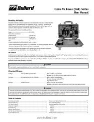
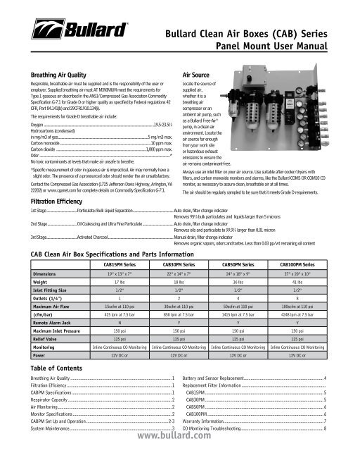
<strong>Air</strong> Source<br />
www.bullard.com<br />
Locate the source of<br />
supplied air,<br />
whether it is a<br />
breathing air<br />
compressor or an<br />
ambient air pump, such<br />
as a <strong>Bullard</strong> Free-<strong>Air</strong> ®<br />
pump, in a clean air<br />
environment. Locate the<br />
air source far enough<br />
from your work site<br />
or hazardous exhaust<br />
emissions to ensure the<br />
air remains contaminant-free.<br />
Always use an inlet filter on your air source. Use suitable after-cooler/dryers with<br />
filters, and carbon monoxide monitors and alarms, like the <strong>Bullard</strong> COM5 OR COM10 CO<br />
monitor, as necessary to assure clean, breathable air at all times.<br />
The air should be regularly sampled to be sure that it meets Grade D requirements.<br />
1st Stage ..................................Particulate/Bulk Liquid Separation .............................................. Auto drain, filter change indicator<br />
Removes 95% bulk particulates and liquids larger than 5 microns<br />
2nd Stage .................................Oil Coalescing and Ultra Fine Particulate ................................... Auto drain, filter change indicator<br />
Removes oils and particulate to 99.9% larger than 0.01 micron<br />
3rd Stage ..................................Activated Charcoal .......................................................................... <strong>Manual</strong> drain, filter change indicator<br />
Removes organic vapors, odors and tastes. Less than 0.03 pp/wt remaining oil content<br />
<strong>CAB</strong> <strong>Clean</strong> <strong>Air</strong> Box Specifications and Parts Information<br />
<strong>CAB</strong>15PM <strong>Series</strong> <strong>CAB</strong>30PM <strong>Series</strong> <strong>CAB</strong>50PM <strong>Series</strong> <strong>CAB</strong>100PM <strong>Series</strong><br />
Dimensions 19” x 13” x 7” 22” x 14” x 7” 24” x 18” x 9” 27” x 20” x 10”<br />
Weight 17 lbs 18 lbs 36 lbs 41 lbs<br />
Inlet Fitting Size 1/2” 1/2” 1/2” 1/2”<br />
Outlets (1/4”) 1 2 4 8<br />
Maximum <strong>Air</strong> Flow 15scfm at 110 psi 30scfm at 110 psi 50scfm at 110 psi 100scfm at 110 psi<br />
(cfm/bar) 425 lpm at 7.5 bar 850 lpm at 7.5 bar 1415 lpm at 7.5 bar 4248 lpm at 7.5 bar<br />
Remote Alarm Jack N Y Y Y<br />
Maximum Inlet Pressure 150 psi 150 psi 150 psi 150 psi<br />
Relief Valve 125 psi 125 psi 125 psi 125 psi<br />
Monitoring Inline Continuous CO Monitoring Inline Continuous CO Monitoring Inline Continuous CO Monitoring Inline Continuous CO Monitoring<br />
Power 12V DC or 12V DC or 12V DC or 12V DC or<br />
Table of Contents<br />
Breathing <strong>Air</strong> Quality ......................................................................................... 1<br />
Filtration Efficiency ............................................................................................ 1<br />
<strong>CAB</strong>PM Specifications ........................................................................................ 1<br />
Respirator Capacity ........................................................................................... 2<br />
<strong>Air</strong> Monitoring .................................................................................................... 2<br />
Monitor Specifications ....................................................................................... 2<br />
<strong>CAB</strong>PM Set Up and Operation ........................................................................2-3<br />
System Maintenance .......................................................................................... 3<br />
Battery and Sensor Replacement ...................................................................... 4<br />
Replacement Filter Information ..........................................................................<br />
<strong>CAB</strong>15PM ........................................................................................................ 5<br />
<strong>CAB</strong>30PM ........................................................................................................ 5<br />
<strong>CAB</strong>50PM ........................................................................................................ 6<br />
<strong>CAB</strong>100PM ...................................................................................................... 6<br />
Warranty Information ........................................................................................ 7<br />
CO Montioring Troubleshooting......................................................................... 8
Monitor Specifications / Set Up and Operation<br />
2<br />
Respirator Capacity<br />
The <strong>Bullard</strong> <strong>Clean</strong> <strong>Air</strong> Box is supplied with up to 8 quick-disconnect fittings. The actual<br />
number of respirators that may be connected to the <strong>CAB</strong> is dependent on the inlet<br />
pressure to the <strong>Bullard</strong> air filtration system and the air flow and pressure requirements<br />
of the respirator being worn. <strong>Air</strong> supply pressure ranges and approved hose lengths for<br />
a respirator can be found in the manufacturer’s <strong>User</strong> Instructions for the respirator.<br />
<strong>Air</strong> Monitoring<br />
The air flows through the CO monitor and a small amount (~0.5 lpm) is diverted<br />
through a preset internal regulator and flow restrictor, delivering a continuous flow<br />
of sample air to the sensor chamber. The monitor will analyze the air and display the<br />
CO concentration in parts-per-million (ppm). The Green LED located on the face of the<br />
monitor will illuminate during normal operation when the CO level is below the CO alarm<br />
point (10 ppm US and 5 ppm International). If the CO level rises above the alarm set<br />
point, the Red (alarm) LED on the face of the monitor will illuminate and an audible alarm<br />
will sound.<br />
Function Modes<br />
The knob on the front of the COM10 or COM5 monitor sets the functions for the CO<br />
monitor and can be switched to RUN, TEST and CAL.<br />
RUN mode is the operation/detection mode. The monitor must be in the RUN mode<br />
to monitor the supplied breathing air. Supplied air must be turned on and flowing to<br />
the instrument while in this mode. When the supplied air is off or interrupted while the<br />
monitor is in the RUN mode, the low flow alarm will sound and LF will be displayed on the<br />
monitor until the supplied air is turned on.<br />
TEST mode allows for bump testing of the sensor or for silencing of the low flow alarm<br />
when supplied air is shut off. To perform a bump test, place the monitor in the TEST<br />
mode and flow the calibration gas into the center of the knob. The reading on the monitor<br />
should be 10 +/- 1 if applying CO gas. The reading on the monitor should be zero or 1 if<br />
applying the zero gas. In the test mode, the supplied air will not be monitored and there<br />
is no need to turn the supplied air off when entering this mode. Unit must be zeroed after<br />
bump test is performed.<br />
CAL mode is the calibration and zero calibration mode. When the monitor is switched<br />
to the CAL mode, the supplied air will not be flowing to the sensor and there is no need<br />
to shut off the supplied air. When in the CAL mode, (AC) AutoCal ® will be displayed.<br />
Pressing the On/Off button while in this mode will change the display to (AO) AutoZero.<br />
For calibration and zeroing instruction, see the Calibration section.<br />
F1 (fault) is indicated on the display when the cam valve is not positioned securely in<br />
one of these three modes.<br />
Error Codes<br />
rC indicates that the system requires a recalibration.<br />
lb indicates a low battery.<br />
Monitor Specs<br />
Operating Temperature .............................................................-4ºF to 120ºF (-20ºC to 48.89ºC)<br />
Humidity Range ...................................................................................................................0 – 100%<br />
Sample Flow Rate ..................................................................................................................0.85 cfh<br />
Display .................................................................................................................................2 digit LCD<br />
Sensor Type ............................................................................Electrochemical; Carbon Monoxide<br />
Range ..................................................................................................................................0 – 99 ppm<br />
Calibration ..................................... <strong>Manual</strong> CO and Zero - Auto Cal ® ; No manual adjustments<br />
Alarm Setting....................................................................................10 ppm (5 ppm International)<br />
<strong>CAB</strong> <strong>Clean</strong> <strong>Air</strong> Box Set Up and Operation<br />
WARNINg<br />
Always operate the <strong>CAB</strong> <strong>Clean</strong> <strong>Air</strong> Box in the upright position. Failure to comply may<br />
result in one or all of the following:<br />
Auto drains will not function properly. This may result in the contamination of the<br />
CO monitor and cause water to be passed through the air supply hose and into the<br />
worker’s respirator.<br />
Auto drains may become clogged. See user instructions for information on cleaning<br />
or replacing auto drains.<br />
Filters may accumulate moisture and/or contaminants. See user instructions for<br />
information on replacing filter.<br />
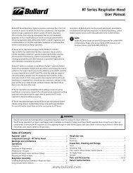
Set Up and Operation<br />
Power Supply Requirements<br />
The <strong>Bullard</strong> <strong>CAB</strong> <strong>Panel</strong> <strong>Mount</strong> filtration<br />
systems are not supplied with an AC<br />
power cord. The panel must be wired<br />
for either110 or 220VAC, 50/60 Hz,<br />
Black – Hot<br />
single phase operation. Proper wiring<br />
White – Neutral<br />
should be performed by a qualified<br />
Green - Ground<br />
electrician in accordance with local<br />
and national electrical codes and is the<br />
responsibility of the user.<br />
Fig. 1<br />
See below for proper wiring<br />
information (Figure 1).<br />
Prior to hooking up the incoming air supply lines, purge all moisture by running the air<br />
before connecting the <strong>CAB</strong>.<br />
Attach to incoming air source; do not exceed 150 psi.<br />
Insure the AC Power Supply is operational.<br />
Flip switch on Control Box to ON position. (Figure 2)<br />
Insure the knob on the CO Monitor is rotated to the<br />
TEST position. This will prevent the Low Flow alarm<br />
Fig. 2<br />
from sounding during start up if no air is flowing.<br />
(Figure 2)<br />
Push the ON button located behind the front cover of the CO Monitor. (Figure 3)<br />
Wait for the 60 second countdown shown on the CO Monitor display screen.<br />
Calibrate the CO Monitor if<br />
necessary. See Calibration<br />
Instructions.<br />
Connect the remote alarm<br />
assembly (optional) to the remote<br />
On/Off<br />
alarm jack located on the control Button<br />
box.<br />
Fig. 3<br />
www.bullard.com<br />
Warning Signals .......................................................................... Normal Operation - Green Light<br />
...............................................................................................................................High CO - Red Light<br />
..........................................................................................................High CO - Audible alarm (90db)<br />
.................................................................................................Low Battery - Amber Light (Blinking)<br />
...................................................................................................Low Battery - Audible alarm (chirp)<br />
...........................................................................................Low Flow Alarm - Audible alarm (90db)<br />
Warranty .................................................................................. Two years on sensor and monitor<br />
Shielding Internal RFI/EMI coating
NOTE<br />
The knob must be in RUN position for active monitoring of CO in the air supply.<br />
Attach respirators and adjust regulator to appropriate pressure per respirator<br />
manufacturer’s recommendation. For units with independent regulators, adjust each<br />
regulator as appropriate for each outlet being used.<br />
Calibration and Zero-Point Process<br />
Zero-Point Adjustment<br />
NOTE:<br />
It is recommended that the <strong>Clean</strong> <strong>Air</strong> box be under pressure with no air going<br />
through the outlet fitting when perfroming zero point adjustment or calibration.<br />
NOTE:<br />
If monitor has been relocated to a different working area and ambient<br />
temperatures change, allow the unit to stabilize for 15-20 minutes prior to Zero<br />
Point adjustment and calibration.<br />
Zero Adjustment Procedure<br />
Remove the front cover of the CO Monitor.<br />
Push the ON button. The unit will beep and begin a 60 second countdown.<br />
Rotate the knob located on the front of the CO Monitor to the CAL position.<br />
“AC” will appear on the display.<br />
Press and hold the On/Off button until it beeps.<br />
“AO” will now appear on the display.<br />
Attach the regulator to the zero gas cylinder.<br />
Insert the calibration connector fitting into the center of the knob on the front of the<br />
monitor.<br />
Open the cylinder valve fully. The flow rate is preset, so there is no need to adjust it.<br />
The red LED will continue to blink for approximately 90 seconds during which the zero<br />
adjustment process will take place.<br />
Watch for the green LED to begin blinking. This indicates a successful zero.<br />
With the Zero air still flowing, turn the knob to TEST. The reading should be Co 0 or Co 1.<br />
If any other reading is displayed, repeat the Zero Point Adjustment.<br />
Close the regulator on zero gas cylinder completely. Remove the calibration connector<br />
fitting from the center of the knob.<br />
With the incoming air flowing, turn the knob to RUN.<br />
NOTE<br />
Knob must be in RUN position for active monitoring of CO in the air supply.<br />
Calibration Instructions<br />
The COM5 and COM10 are Auto-Cal instruments. All calibration adjustments are made<br />
automatically.<br />
Monitor calibration should be performed monthly or whenever the reading may be<br />
questionable. A calibration schedule should be maintained for future reference. To obtain<br />
an accurate calibration, we recommend the use of <strong>Bullard</strong> calibration kits.<br />
Calibration Procedure<br />
If necessary, remove the front cover of the CO monitor and push the ON button.<br />
Rotate the knob located on the front of the monitor to the CAL position.<br />
“AC” will appear on the display.<br />
Attach the regulator to the calibration gas cylinder (10 ppm CO required).<br />
Insert the calibration connector fitting into the center of the knob.<br />
<strong>Bullard</strong> <strong>Clean</strong> <strong>Air</strong> <strong>Boxes</strong> (<strong>CAB</strong>) <strong>Series</strong><br />
<strong>Panel</strong> <strong>Mount</strong> <strong>User</strong> <strong>Manual</strong><br />
www.bullard.com<br />
Open the cylinder valve fully. The flow rate is preset, and there is no need to adjust it.<br />
The Red LED on the front of the monitor will continue to blink for approximately 90<br />
seconds during which the calibration process will take place.<br />
Watch for the green LED to blink. This indicates a successful calibration.<br />
With the 10ppm gas still flowing, turn the knob to TEST. The reading should be Co<br />
10+/-1. If any other reading is displayed in the test mode, repeat both the Zero Point<br />
adjustment and CO calibration.<br />
Close the regulator on CO gas cylinder completely and remove the calibration connector<br />
fitting from the center of the knob.<br />
With the zero air flowing, rotate the knob to the RUN position.<br />
NOTE:<br />
Typical calibration takes approximately 90 seconds. If unit will not calibrate<br />
within 3 minutes, repeat the calibration steps with compressed air turned off.<br />
If the problem persists, contact the <strong>Bullard</strong> Customer Service Department at<br />
1-877-BULLARD (285-5273).<br />
NOTE:<br />
Knob must be in RUN position for active monitoring of CO in the air supply.<br />
Shut Down<br />
Make sure all personnel have left the work area.<br />
Shut off the incoming air to the <strong>Clean</strong> <strong>Air</strong> Box.<br />
Release air pressure from the box by pulling the relief valve ring out.<br />
Turn the CO Monitor off by pressing and holding the ON/OFF button for three seconds.<br />
You will hear three short beeps to let you know the CO monitor is OFF.<br />
Turn the control box switch to the OFF position.<br />
Disconnect the airline hoses.<br />
Install dust caps to prevent entry of debris into the outlet fittings.<br />
System Maintenance<br />
CAUTION<br />
Always depressurize the system before performing service.<br />
Filter Housing/Bowls<br />
Periodic cleaning of the polycarbonate bowls may become necessary. Remove the auto<br />
drains. <strong>Clean</strong> the bowls with a mild soapy solution. Re-install into the filter housing.<br />
Auto Drains<br />
The automatic drains are designed to remove bulk liquid contaminants. The drains (1st<br />
and 2nd stages only) will automatically drain the liquids after the level has reached 1/3 of<br />
the bowl capacity. For periodic cleaning, use mild soap and water.<br />
Filter Change<br />
The filtration system consists of a filter change indicator, which will gradually change<br />
from green to orange when filter life is spent.<br />
NOTE<br />
<strong>Air</strong> must be flowing through the <strong>Clean</strong> <strong>Air</strong> Box before the filter change indicators<br />
will function.<br />
Drain Lines<br />
Make sure the auto drain tubes are placed in the holes at the bottom of the box to allow<br />
liquids to drain outside of the box<br />
Set Up and Operation / Shut Down<br />
3
System Maintenance / Battery and Sensor Replacement<br />
4<br />
Calibration<br />
Monitor calibration should be performed monthly or whenever the reading may be<br />
questionable. A calibration schedule should be maintained for future reference. To obtain<br />
an accurate calibration, we recommend the use of <strong>Bullard</strong> calibration kits.<br />
Part Number:<br />
<strong>CAB</strong>CK Calibration kit for CO monitor, 10 ppm CO, zero air, regulator and case -<br />
34 liter size<br />
<strong>CAB</strong>CK17L Calibration kit for CO monitor, 10ppm CO, zero air and regulator -<br />
17 liter size<br />
<strong>CAB</strong>RS New CO sensor<br />
NOTE<br />
To assure sensor accuracy, calibration of the monitor is required. If you cannot<br />
obtain an accurate calibration, sensor replacement may be necessary. Contact<br />
<strong>Bullard</strong> Customer Service Department for ordering information.<br />
Battery Replacement<br />
CO Monitor Battery Replacement: A 9-volt battery is installed under the front panel cover<br />
to provide power to the CO monitor. This monitor may also run solely on DC power if the<br />
clean air box is not attached to an AC power supply.<br />
To replace the 9-volt battery, remove the panel cover from the front of the CO monitor.<br />
Lift it off from either the left or right side. If a 9-volt battery is being used to power the<br />
monitor and the battery power becomes too low, the monitor will indicate low battery<br />
(LB) on the display to indicate it is time to change the battery. (Figure 4)<br />
Fig. 4<br />
Sensor Replacement<br />
NOTE<br />
Important: Before installing a replacement sensor, verify<br />
that you have the correct sensor. The <strong>CAB</strong>RS is the<br />
replacement sensor for all COM10 or COM5 monitors with<br />
serial numbers with a suffix “A”, and serial numbers with<br />
NO suffix. The <strong>CAB</strong>RS2 is the replacement sensor for all<br />
COM10<br />
or COM5<br />
monitors<br />
www.bullard.com<br />
WARNINg<br />
Removing the front of the housing by prying at the top will result in damage to the<br />
housing. This damage is not covered under warranty.<br />
Fig. 6<br />
Screws<br />
Pry here<br />
Battery<br />
Cover<br />
Fig. 5<br />
<strong>CAB</strong>RS<br />
<strong>CAB</strong>RS2<br />
with serial numbers with a<br />
suffix “B”. Also, the monitors<br />
that require the <strong>CAB</strong>RS2 will<br />
have an extra board to which<br />
the sensor mounts (Figure 5).<br />
The sensor is easily accessible by<br />
removing the front of the housing<br />
from the COM5 or COM10<br />
monitor.<br />
To gain access to the sensor,<br />
remove the four screws on the<br />
front of the CO monitor only. After<br />
removing the four screws, gently<br />
pry the front of the housing off<br />
from the bottom of the housing.<br />
(Figure 6)<br />
Gently pull out the old sensor.<br />
Remove the shorting clip cover from the new sensor.<br />
Failure to remove shorting<br />
clip (not shown) will result<br />
in inability to calibrate.<br />
Align pins and gently push<br />
the new sensor into the<br />
sockets (Figure 7).<br />
Replace the front cover of<br />
the monitor when sensor<br />
replacement is complete.<br />
Ensure LED lights are<br />
Fig. 7<br />
aligned with housing before<br />
securing front cover with<br />
screws.<br />
After replacing the sensor, allow the instrument to warm up for at least 30 minutes. The<br />
new sensor must be zeroed and calibrated before first use. See Zero Point Adjustment<br />
and Calibration Instructions.
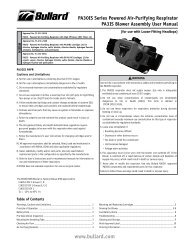
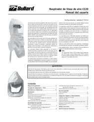
Replacement Parts Breakdown<br />
Filter Change Indicator<br />
First Stage Filter<br />
Second Stage Filter<br />
Third Stage Filter<br />
<strong>CAB</strong>15PM (15 cfm)<br />
Description Part Number<br />
CO Monitor ............................................................ COM5 or COM10<br />
Filter Change Indicator .................................................... <strong>CAB</strong>30FCI<br />
Pressure Regulator with Gauge ....................................... <strong>CAB</strong>REG1<br />
Relief Valve, 125 psi ..............................................................41PRV<br />
Hansen Coupling .............................................................. <strong>CAB</strong>QDHA<br />
Schrader Coupling .............................................................<strong>CAB</strong>QDSC<br />
Cejn Coupling ....................................................................<strong>CAB</strong>QDCE<br />
Filter Change Indicator<br />
First Stage Filter<br />
Second Stage Filter<br />
Third Stage Filter<br />
<strong>CAB</strong>30PM (30 cfm)<br />
Description Part Number<br />
CO Monitor ............................................................ COM5 or COM10<br />
Filter Change Indicator .................................................... <strong>CAB</strong>30FCI<br />
Pressure Regulator with Gauge ....................................... <strong>CAB</strong>REG1<br />
Independent Regulator ..................................................... <strong>CAB</strong>REG4<br />
Pressure Gauge for Independent Regulator........................S19685<br />
Relief Valve, 125 psi ..............................................................41PRV<br />
Hansen Coupling .............................................................. <strong>CAB</strong>QDHA<br />
Schrader Coupling .............................................................<strong>CAB</strong>QDSC<br />
<strong>Bullard</strong> <strong>Clean</strong> <strong>Air</strong> <strong>Boxes</strong> (<strong>CAB</strong>) <strong>Series</strong><br />
<strong>Panel</strong> <strong>Mount</strong> <strong>User</strong> <strong>Manual</strong><br />
www.bullard.com<br />
Pressure Gauge<br />
Outlet Coupler<br />
Dust Cap<br />
CO Monitor<br />
Pressure Regulator<br />
Description Part Number<br />
Snap-Tite Coupling ........................................................... <strong>CAB</strong>QDSN<br />
Hansen Stainless Coupler .................................................<strong>CAB</strong>QDSS<br />
Dust Cap, Universal ....................................................... <strong>CAB</strong>QDCAP<br />
A Filter Element - First Stage ..........................................<strong>CAB</strong>30FEA<br />
B Filter Element - Second Stage .....................................<strong>CAB</strong>30FEB<br />
C Filter Element - Third Stage .........................................<strong>CAB</strong>30FEC<br />
CO Sensor ..............................................................................<strong>CAB</strong>RS<br />
Pressure Gauge<br />
Pressure Relief Valve<br />
Outlet Coupler<br />
Dust Cap<br />
CO Monitor<br />
Pressure Regulator<br />
Description Part Number<br />
Cejn Coupling ....................................................................<strong>CAB</strong>QDCE<br />
Snap-Tite Coupling ........................................................... <strong>CAB</strong>QDSN<br />
Hansen Stainless Coupler .................................................<strong>CAB</strong>QDSS<br />
Dust Cap, Universal ....................................................... <strong>CAB</strong>QDCAP<br />
A Filter Element - First Stage ..........................................<strong>CAB</strong>30FEA<br />
B Filter Element - Second Stage ......................................<strong>CAB</strong>30FEB<br />
C Filter Element - Third Stage .........................................<strong>CAB</strong>30FEC<br />
CO Sensor ..............................................................................<strong>CAB</strong>RS<br />
Replacement Filter Information<br />
5
Replacement Filter Information<br />
6<br />
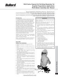
Filter Change Indicator<br />
Inlet Fitting<br />
First Stage Filter<br />
Second Stage Filter<br />
Third Stage Filter<br />
<strong>CAB</strong>50PM (50 cfm)<br />
Description Part Number<br />
CO Monitor ............................................................ COM5 or COM10<br />
Filter Change Indicator .................................................... <strong>CAB</strong>50FCI<br />
Pressure Gauge ....................................................................S19686<br />
Pressure Regulator ........................................................... <strong>CAB</strong>REG2<br />
Independent Regulator ..................................................... <strong>CAB</strong>REG4<br />
Pressure Gauge for Independent Regulator........................S19685<br />
Relief Valve, 125 psi ..............................................................41PRV<br />
Hansen Coupling .............................................................. <strong>CAB</strong>QDHA<br />
Schrader Coupling .............................................................<strong>CAB</strong>QDSC<br />
Filter Change Indicator<br />
Inlet Fitting<br />
First Stage Filter<br />
Second Stage Filter<br />
Third Stage Filter<br />
<strong>CAB</strong>100PM (100 cfm)<br />
Description Part Number<br />
CO Monitor ............................................................ COM5 or COM10<br />
Filter Change Indicator .................................................. <strong>CAB</strong>100FCI<br />
Pressure Gauge ....................................................................S19686<br />
Pressure Regulator ........................................................... <strong>CAB</strong>REG3<br />
Independent Regulator ..................................................... <strong>CAB</strong>REG4<br />
Pressure Gauge for Independent Regulator........................S19685<br />
Relief Valve, 125 psi ..............................................................41PRV<br />
Hansen Coupling .............................................................. <strong>CAB</strong>QDHA<br />
Schrader Coupling .............................................................<strong>CAB</strong>QDSC<br />
www.bullard.com<br />
Pressure Relief Valve<br />
Pressure Gauge<br />
CO Monitor<br />
Pressure Regulator<br />
Outlet Coupler<br />
Dust Cap<br />
Description Part Number<br />
Cejn Coupling ....................................................................<strong>CAB</strong>QDCE<br />
Snap-Tite Coupling ........................................................... <strong>CAB</strong>QDSN<br />
Hansen Stainless Coupler .................................................<strong>CAB</strong>QDSS<br />
Dust Cap, Universal ....................................................... <strong>CAB</strong>QDCAP<br />
A Filter Element - First Stage ..........................................<strong>CAB</strong>50FEA<br />
B Filter Element - Second Stage ......................................<strong>CAB</strong>50FEB<br />
C Filter Element - Third Stage .........................................<strong>CAB</strong>50FEC<br />
CO Sensor ..............................................................................<strong>CAB</strong>RS<br />
Pressure Regulator<br />
Pressure Gauge<br />
CO Monitor<br />
Dust Cap<br />
Outlet Coupler<br />
Pressure Relief Valve<br />
Description Part Number<br />
Cejn Coupling ....................................................................<strong>CAB</strong>QDCE<br />
Snap-Tite Coupling ........................................................... <strong>CAB</strong>QDSN<br />
Hansen Stainless Coupler .................................................<strong>CAB</strong>QDSS<br />
Dust Cap, Universal ....................................................... <strong>CAB</strong>QDCAP<br />
A Filter Element - First Stage ........................................<strong>CAB</strong>100FEA<br />
B Filter Element - Second Stage ....................................<strong>CAB</strong>100FEB<br />
C Filter Element - Third Stage .......................................<strong>CAB</strong>100FEC<br />
CO Sensor ..............................................................................<strong>CAB</strong>RS
One Year Limited Warranty<br />
<strong>Bullard</strong> warrants to the original purchaser that the <strong>Clean</strong> <strong>Air</strong> Box will be free<br />
of defects in material and workmanship under normal use and service for a<br />
period of one (1) year from the date of purchase. <strong>Bullard</strong>’s obligation under<br />
this warranty is limited to repairing or replacing, at its option, articles that<br />
are returned within the warranty period and that are, after examination,<br />
shown to <strong>Bullard</strong>’s satisfaction to be defective, subject to the following<br />
limitations.<br />
a) <strong>Clean</strong> <strong>Air</strong> Box must be returned to the <strong>Bullard</strong> factory with shipping<br />
charges prepaid.<br />
b) <strong>Clean</strong> <strong>Air</strong> Box must not be altered from its original factory configuration.<br />
c) <strong>Clean</strong> <strong>Air</strong> Box must not have been misused, subjected to negligent use, or<br />
damaged in transport.<br />
d) The date of purchase is within the one year warranty period. (A copy of<br />
the purchaser’s original invoice showing the date of purchase is required<br />
to validate warranty coverage.)<br />
In no event shall <strong>Bullard</strong> be responsible for damages for loss of use or other<br />
indirect, incidental, consequential or special costs, expenses or damages<br />
incurred by the purchaser, notwithstanding that <strong>Bullard</strong> has been advised of<br />
the possibility of such damages.<br />
ANY IMPLIED WARRANTIES, INCLUDING WARRANTIES OF<br />
MERCHANTABILITY AND FITNESS FOR A PARTICULAR PURPOSE, ARE<br />
LIMITED IN DURATION TO ONE (1) YEAR FROM THE DATE OF PURCHASE OF<br />
THIS PRODUCT.<br />
Some states do not allow the exclusion or limitation of incidental or<br />
consequential damages, or allow limitations on how long an implied warranty<br />
lasts, so the above limitations or exclusion may not apply to you. This<br />
warranty gives you specific legal rights, and you may have other rights which<br />
vary from state to state.<br />
<strong>Bullard</strong> <strong>Clean</strong> <strong>Air</strong> <strong>Boxes</strong> (<strong>CAB</strong>) <strong>Series</strong><br />
<strong>Panel</strong> <strong>Mount</strong> <strong>User</strong> <strong>Manual</strong><br />
www.bullard.com<br />
Return Authorization<br />
The following steps must be completed before <strong>Bullard</strong> will accept any<br />
returned goods. Please read carefully.<br />
Follow the steps outlined below to return goods to <strong>Bullard</strong> for repair or<br />
replacement under warranty or for paid repairs:<br />
1. Contact <strong>Bullard</strong> Customer Service by telephone or in writing at:<br />
<strong>Bullard</strong><br />
1898 Safety Way<br />
Cynthiana, KY 41031-9303<br />
Toll-Free: 877-BULLARD (285-5273)<br />
Phone: 859-234-6611<br />
In your correspondence or conversation with Customer Service, describe<br />
the problem as completely as possible. For your convenience, the<br />
representative will try to help you correct the problem over the phone.<br />
2. Verify with your representative that the product should be returned to<br />
<strong>Bullard</strong>. Customer Service will provide you with written permission and a<br />
return authorization number.<br />
3. Before returning the product, decontaminate and clean it to remove<br />
any hazardous materials which may have settled on the product during<br />
use. Laws and/or regulations prohibit the shipment of hazardous or<br />
contaminated materials. Products suspected to be contaminated will be<br />
professionally discarded at the customer’s expense.<br />
4. Ship returned products, including those under warranty, with all<br />
transportation charges pre-paid. <strong>Bullard</strong> cannot accept returned goods on<br />
a freight collect basis.<br />
5. Returned products will be inspected upon return to the <strong>Bullard</strong> facility.<br />
<strong>Bullard</strong> Customer Service will telephone you with a quote for required<br />
repair work which is not covered by warranty. If the cost of repairs<br />
exceeds stated quote by more than 20%, your representative will call you<br />
for authorization to complete repairs.<br />
Warranty Information<br />
7
Co Montior Troubleshooting guide<br />
Monitor will not calibrate at 10 ppm.<br />
Monitor will not successfully complete a zero point adjustment. • Wait 5 minutes and repeat steps 1-4 above.<br />
Monitor displays a (-0) reading or rC. • Wait 5 minutes and repeat steps 1-6 above.<br />
Monitor zeroes during the zero point adjustment and the reading<br />
elevates after returning to the RUN mode.<br />
Monitor will not turn ON.<br />
Monitor does not display flashing green light after calibration or a<br />
partial display appears on the monitor screen.<br />
Americas:<br />
E.D. <strong>Bullard</strong> Company<br />
1898 Safety Way<br />
Cynthiana, KY 41031-9303<br />
Toll free: 877-BULLARD (285-5273)<br />
Tel: 859-234-6616<br />
Fax: 859-234-8987<br />
www.bullard.com<br />
Europe:<br />
<strong>Bullard</strong> gmbH<br />
Lilienthalstrasse 12<br />
53424 Remagen • Germany<br />
Tel: +49-2642 999980<br />
Fax : +49-2642 9999829<br />
www.bullardextrem.com<br />
1. Prior to performing a calibration, allow the temperature of the monitor to<br />
stabilize to the environment in which it will be used for several minutes.<br />
2. The <strong>Clean</strong> <strong>Air</strong> Box should be under pressure with air flowing to the box with<br />
no air going through the outlet couplers (i.e. under static pressure).<br />
3. Perform a zero point adjustment using impurity-free air.<br />
4. If the instrument zeroes, perform a calibration using 10 ppm CO.<br />
5. Verify that the calibration gas is 10 ppm and the gas cylinder is not empty. (Gauges are available.)<br />
6. If the instrument will not calibrate, remove the air supply and repeat both<br />
the zero point adjustment and the 10 ppm CO calibration.<br />
7. If the instrument will not calibrate, replace the sensor and repeat both the zero point adjustment and the 10<br />
ppm CO calibration.<br />
A. Allow unit to stabilize in the run mode for 5 minutes.<br />
B. Repeat steps 1-6 above.<br />
C. If the unit will not calibrate, the supply air may be contaminated.<br />
D. Check the supply air for CO level.<br />
• Verify that the ON/OFF button under the front cover of the monitor has<br />
been pressed to activate the monitor<br />
• Check AC power supply<br />
1. Confirm the ON/OFF switch on the control box is in the ON position<br />
2. Confirm AC power cord is connected to working outlet (Portable)<br />
3. Confirm unit is wired correctly (<strong>Panel</strong> mount)<br />
• Using Battery back up<br />
1. Confirm the AA batteries are good – replace if needed<br />
• Using 9V battery installed in monitor<br />
1. Verify that the battery is good – replace if needed<br />
• If the power supply is good and the monitor will not power up, return it to the factory for repair or replacement.<br />
• With the monitor ON and the unit on battery power only, remove and reinstall the 9 volt battery.<br />
• Repeat steps 1-6 above.<br />
Monitor does not turn OFF. • Monitor must be in the RUN or TEST mode.<br />
• The rotary cam switch is not locked in the CAL, TEST or RUN position.<br />
• Turn the switch knob slightly until it is in the correct position.<br />
NOTE<br />
Monitor displays an (F1) reading.<br />
1. AC appears on the display if attempting to go to CAL mode.<br />
2. CO and an alternating number appears on the display if the unit<br />
is in the TEST mode.<br />
3. A number (PPM content of CO in the compressed air) appears<br />
on the display if attempting to go to the RUN mode.<br />
• This can occur when the ON / OFF button is pushed while the monitor is in<br />
the fault mode with F1 showing on the display.<br />
Monitor displays (8.88, 2F or 9E) with flashing lights.<br />
• Continue to push the ON / OFF button until F1 is shown on the display.<br />
• Turn the switch knob slightly to lock the monitor into the CAL, TEST or RUN mode.<br />
• Check power supply.<br />
Monitor shuts down after 60 second countdown.<br />
• Verify that the battery is good.<br />
• If the power supply is good and the monitor will not power up, return it to the factory for repair or replacement.<br />
This indicates a low battery condition and the 9V battery in the CO monitor<br />
Monitor displays “lb”.<br />
should be replaced.<br />
• This is normal for TEST mode and no action is necessary.<br />
Yellow caution LED flashes.<br />
• If the unit is not in TEST mode, then it may indicate a low battery condition.<br />
Replace the 9V battery in the CO monitor.<br />
Asia-Pacific:<br />
<strong>Bullard</strong> Asia Pacific Pte. Ltd.<br />
LHK Building<br />
701, Sims Drive, #04-03<br />
Singapore 387383<br />
Tel: +65-6745-0556<br />
Fax: +65-6745-5176<br />
www.bullard.com<br />
©2009 <strong>Bullard</strong>. All rights reserved.<br />
ISO 9001<br />
certified<br />
6081258007B (1009)