PoP Test Socket - Chip Scale Review
PoP Test Socket - Chip Scale Review
PoP Test Socket - Chip Scale Review

Create successful ePaper yourself
Turn your PDF publications into a flip-book with our unique Google optimized e-Paper software.
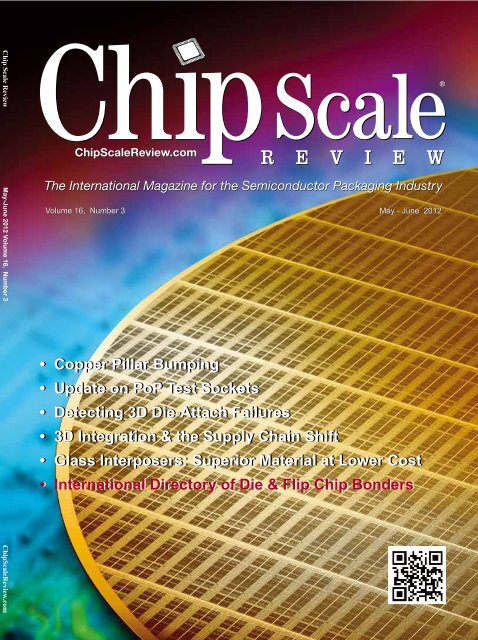
<strong>Chip</strong> <strong>Scale</strong> <strong>Review</strong> May-June 2012 Volume 16, Number 3 <strong>Chip</strong><strong>Scale</strong><strong>Review</strong>.com<br />
Volume 16, Number 3 May - June 2012<br />
• Copper Pillar Bumping<br />
• Update on <strong>PoP</strong> <strong>Test</strong> <strong>Socket</strong>s<br />
• Detecting 3D Die-Attach Failures<br />
• 3D Integration & the Supply Chain Shift<br />
• Glass Interposers: Superior Material at Lower Cost<br />
• International Directory of Die & Flip <strong>Chip</strong> Bonders<br />
<strong>Chip</strong> <strong>Scale</strong> <strong>Review</strong> Jan/Feb 2012 [<strong>Chip</strong><strong>Scale</strong><strong>Review</strong>.com]<br />
1
2<br />
MRSI-M5<br />
Typical Applications<br />
• Microwave / RF Modules<br />
• MEMS<br />
• Advanced Semiconductor Packages<br />
• Multi-chip Modules<br />
• Hybrid Devices<br />
• Photonic Packages<br />
©2012 Newport Corporation<br />
<strong>Chip</strong> <strong>Scale</strong> <strong>Review</strong> Jan/Feb 2012 [<strong>Chip</strong><strong>Scale</strong><strong>Review</strong>.com]<br />
MRSI-M5 Setting the Standard<br />
for 5 Micron Die Bonding<br />
Accurate, stable, fast and reliable, Newport’s MRSI-M5 provides advanced<br />
assembly solutions for complex epoxy die attach, eutectic and flip chip<br />
bonding. It’s the next generation assembly work cell you’ve been waiting<br />
for – from the company that has set the industry standard for 20 years.<br />
The MRSI-M5 achieves 5-micron placement accuracy with a highly stable<br />
machine platform and the market’s most advanced lighting and machine<br />
vision. It has a large work area for flexible, high volume production and<br />
“feather touch” force control to handle delicate devices.<br />
With Newport you can rest assured that you are working with an<br />
industry leader who delivers global support, process experience<br />
and manufacturing expertise. Visit newport.com/bond1 for more<br />
information. Or call 978-667-9449.
2<br />
<strong>Chip</strong> <strong>Scale</strong> <strong>Review</strong> May/June 2012 [<strong>Chip</strong><strong>Scale</strong><strong>Review</strong>.com]
<strong>Chip</strong> <strong>Scale</strong> <strong>Review</strong> May/June 2012 [<strong>Chip</strong><strong>Scale</strong><strong>Review</strong>.com]<br />
3
4<br />
40 + years of<br />
And now, the perfect name<br />
Introducing Qinex, the<br />
new brand name for<br />
superior interconnection<br />
solutions from Sensata<br />
Technologies. Qinex, the<br />
new word in perfect<br />
pitch.<br />
<strong>Chip</strong> <strong>Scale</strong> <strong>Review</strong> May/June 2012 [<strong>Chip</strong><strong>Scale</strong><strong>Review</strong>.com]<br />
TM<br />
QUALITY. High-value interconnection<br />
solutions since 1970.<br />
• 24/7 global engineering<br />
• 24/7 global support teams<br />
• Local engineering and sales<br />
• Six Sigma quality management<br />
• Proven, reliable high-volume<br />
manufacturing<br />
• Expert molding, design, and<br />
customization<br />
PARTNERSHIP. In a fierce global<br />
market, only Qinex reliably supports<br />
the innovation, reputation and<br />
competitiveness of your business.<br />
We’ll work with you to get it right,<br />
the first time.<br />
Qi •nex [kuh-nekts] 1. Over 40 years of<br />
reliable burn-in and custom connections;<br />
2. Quality interconnects for nex-gen solutions.<br />
INNOVATION. More I/O choices,<br />
smaller form factors, superior<br />
performance in less time.<br />
• Latest 3D design tools<br />
• On-site model shops<br />
• Rapid prototyping<br />
• Advanced thermal analysis<br />
• Design on demand<br />
• Broad range of innovative<br />
contact designs<br />
40+ years of perfect pitch.<br />
And now, the perfect name.<br />
WEB www.qinex.com<br />
EMAIL qinex@sensata.com<br />
CALL 1-508-236-1306
FEATURE ARTICLES<br />
<strong>PoP</strong> <strong>Test</strong> <strong>Socket</strong> – Challenges and Approaches<br />
Jiachun Zhou (Frank), PhD and Siang Soh IDI<br />
Thin-Gate Acoustic Imaging of Flip <strong>Chip</strong>s<br />
Tom Adams, Sonoscan, Inc.<br />
DEPARTMENTS<br />
From the Publisher<br />
Kim Newman, <strong>Chip</strong> <strong>Scale</strong> <strong>Review</strong><br />
Guest Editorial What’s New with Interposers?<br />
Phil Marcoux, PPM Associates<br />
Market Trends Status of the OSAT Industry<br />
By Sandra Winkler, New Venture Research<br />
Industry News<br />
<strong>Chip</strong> <strong>Scale</strong> <strong>Review</strong> Staff<br />
International Directory of Die Attach & Flip <strong>Chip</strong> Bonders<br />
<strong>Chip</strong> <strong>Scale</strong> <strong>Review</strong> Staff<br />
Guest Editorial 3D Integration and the Supply Chain Shift<br />
Francoise von Trapp, 3D InCites<br />
Advertiser Index, Advertising Sales<br />
CONTENTS<br />
<strong>Chip</strong> <strong>Scale</strong> <strong>Review</strong> May/June 2012 [<strong>Chip</strong><strong>Scale</strong><strong>Review</strong>.com]<br />
32<br />
43<br />
6<br />
9<br />
10<br />
12<br />
36<br />
40<br />
48<br />
5
6<br />
Volume 16, Number 3<br />
The International Magazine for Device and Wafer-level<br />
<strong>Test</strong>, Assembly, and Packaging Addressing<br />
High-density Interconnection of Microelectronic IC's<br />
including 3D packages, MEMS, MOEMS,<br />
RF/Wireless, Optoelectronic and Other<br />
Wafer-fabricated Devices for the 21st Century.<br />
STAFF<br />
Kim Newman Publisher<br />
knewman@chipscalereview.com<br />
Françoise von Trapp Senior Technical Editor<br />
fvontrapp@chipscalereview.com<br />
Sandra Winkler Contributing Editor<br />
slwinkler@newventureresearch.com<br />
Dr. Thomas Di Stefano Contributing Editor<br />
tom@centipedesystems.com<br />
Paul M. Sakamoto Contributing Editor <strong>Test</strong><br />
paul.sakamoto@comcast.net<br />
Jason Mirabito Contributing Legal Editor<br />
mirabito@mintz.com<br />
SUBSCRIPTION--INQUIRIES<br />
<strong>Chip</strong> <strong>Scale</strong> <strong>Review</strong><br />
T 408-429-8585<br />
F 408-429-8605<br />
subs@chipscalereview.com<br />
Advertising Production Inquiries:<br />
Kim Newman<br />
knewman@chipscalereview.com<br />
EDITORIAL ADVISORS<br />
Dr. Thomas Di Stefano Centipede Systems<br />
Andy Mackie Indium Corporation<br />
Guna Selvaduray San Jose State University<br />
C.P. Wong Georgia Institute of Technology<br />
Ephraim Suhir ERS Company<br />
Nick Leonardi Premier Semiconductor Services<br />
John Lau Industrial Tech Research Inst (ITRI)<br />
Alissa Fitzgerald A.M. Fitzgerald & Associates<br />
Joseph Fjelstad Verdant Electronics<br />
Venky Sundaram Georgia Institute of Technology -<br />
3D Systems Packaging Research Center<br />
Rolf Aschenbrenner Fraunhofer Institute<br />
Fred Taber BiTS Workshop<br />
Scott Jewler Powertech Technology Inc.<br />
Arun Gowda GE Global Research<br />
Copyright © 2012 Haley Publishing Inc.<br />
<strong>Chip</strong> <strong>Scale</strong> <strong>Review</strong> (ISSN 1526-1344) is a registered trademark of<br />
Haley Publishing Inc. All rights reserved.<br />
Subscriptions in the U.S. are available without charge to qualified<br />
individuals in the electronics industry. Subscriptions outside of the<br />
U.S. (6 issues) by airmail are $100 per year to Canada or $115 per<br />
year to other countries. In the U.S. subscriptions by first class mail<br />
are $95 per year.<br />
<strong>Chip</strong> <strong>Scale</strong> <strong>Review</strong>, (ISSN 1526-1344), is published six times a<br />
year with issues in January-February, March-April, May-June, July-<br />
August, September-October and November-December. Periodical<br />
postage paid at Los Angeles, Calif., and additional offices.<br />
POSTMASTER: Send address changes to <strong>Chip</strong> <strong>Scale</strong> <strong>Review</strong><br />
magazine, P.O. Box 9522, San Jose, CA 95157-0522<br />
Printed in the United States<br />
<strong>Chip</strong> <strong>Scale</strong> <strong>Review</strong> May/June 2012 [<strong>Chip</strong><strong>Scale</strong><strong>Review</strong>.com]<br />
FROM THE PUBLISHER<br />
The industry is abuzz this time of year with events such as the SEMI Arizona<br />
Forum addressing the 450mm Wafer Transition, the 10th Annual MEMS<br />
Technology presented by Meptec, the Semico IMPACT Conference Series:<br />
The IP Ecosystem and the 62nd Electronic Components & Technology<br />
Conference (ECTC).<br />
If you missed the details of these events in <strong>Chip</strong> <strong>Scale</strong> <strong>Review</strong>'s May monthly<br />
enewsletter CSR Tech Monthly you can catch up on them by visiting <strong>Chip</strong> <strong>Scale</strong><br />
<strong>Review</strong>'s website www.chipscalereview.com<br />
If you have not booked your plans for this year's ECTC being held at the Sheraton<br />
San Diego Hotel & Marina May 29 - June 1st, it is not too late. Read about this year's<br />
event in the Industry News section further in this issue. Over 300 technical papers in 36<br />
sessions are presented covering emerging and contemporary topics, such as MEMS, 3D/<br />
TSV, and RF packaging in addition to the array of standard topics in advanced packaging<br />
technologies, interconnections, materials, assembly manufacturing, system packaging,<br />
optoelectronics, reliability, electronic components, and simulation.<br />
“Typically 25 states and 20 countries submit abstracts,” said Dr. Senol Pekin, the 62nd<br />
ECTC Program Chair. There will be a special appearance by Arizona's Secretary of State<br />
Ken Bennett who will preside over an informal press conference on Tues May 29th to<br />
discuss doing business in Arizona. Pekin further comments, “Arizona typically ranks<br />
fourth in terms of papers presented at the conference". CSR is once again the Official<br />
Media Sponsor for ECTC. Pick up a copy while you are attending the conference. You<br />
will not want to miss the exhibits on May 30-31st. Exhibits Chair Bill Moody comments<br />
“There are a total of 79 exhibitors in 81 booths plus 2 tabletops for a total of 81<br />
exhibitors. This is the most exhibitors we have had at ECTC. 26 are first time exhibitors.<br />
Many of the first time exhibitors are involved in 3D/TSV technology and were attracted<br />
by ECTC's emphasis in this area.”<br />
The technical committee for the 2012 IWLPC - the International Wafer-Level<br />
Packaging Conference is well underway putting the technical program together. Contact<br />
any one of the technical committee members in their track if you wish to submit an<br />
abstract but don't wait there only a few openings left.<br />
Exhibits is officially open and limited to 50 spaces for IWLPC. Contact your CSR<br />
sales rep or visit the IWLPC website www.iwlpc.com for further details. Be sure to mark<br />
your calendar for IWLPC Nov 5-8, 2012 being held at the Doubletree Hotel in San Jose,<br />
California. The Platinum, Gold and Flash Drive Sponsorships are sold out. The Silver<br />
Level Sponsorships, Wi-Fi, Reception, Lunch and Refreshment are still available and are<br />
on a first come, first serve basis.<br />
Enjoy the show(s)!<br />
Kim Newman<br />
Publisher<br />
Let’s Have a Really Big Show<br />
Edward Vincent "Ed" Sullivan (September 28, 1901 – October 13, 1974)
<strong>Chip</strong> <strong>Scale</strong> <strong>Review</strong> May/June 2012 [<strong>Chip</strong><strong>Scale</strong><strong>Review</strong>.com]<br />
7
8<br />
<strong>Chip</strong> <strong>Scale</strong> <strong>Review</strong> May/June 2012 [<strong>Chip</strong><strong>Scale</strong><strong>Review</strong>.com]
GUEST EDITORIAL<br />
I nterposers are emerging as a new<br />
element inside an IC package. In<br />
time they may be as important as<br />
underfill epoxy is to flip chips mounted on<br />
BGA substrates and PCBs.<br />
One of the early uses of an interposer<br />
was to enable interconnection of very fine<br />
pitch (
– – –MARKET TRENDS<br />
O<br />
utsourced semiconductor<br />
assembly and test (OSAT)<br />
companies package bare<br />
integrated circuits (ICs), otherwise known<br />
as die, thus converting these die into<br />
chips. These companies contract with<br />
semiconductor or fabless companies, who<br />
either do not have packaging capability<br />
or do not have sufficient capacity to meet<br />
all their own packaging needs. Thus<br />
OSAT companies are also referred to as<br />
contractors.<br />
What Does The package Do?<br />
The package surrounding the die<br />
provides mechanical protection, fans the<br />
electrical connections to something that<br />
can be routed to a PCB, and can have<br />
thermal enhancements such as heat sinks,<br />
heat slugs, and thermal interface materials<br />
(TIMs). All these chips are tested prior<br />
to placement on the PCB, and testing is<br />
a service many of the OSAT companies<br />
offer.<br />
Having the OSAT company develop<br />
leading-edge packages makes sense. The<br />
research and development cost associated<br />
with a given package can be spread over<br />
many companies, and thus be more cost<br />
effective for the OEMs.<br />
There are approximately 60 OSATs<br />
around the world competing for the<br />
outsourced package assembly dollars.<br />
The top ten comprise 60% of this OSAT<br />
market, as seen in Figure 1. Strategies<br />
vary, with some companies specializing<br />
in assembling multitudes of smaller<br />
packages, as is Carsem’s strategy, and<br />
others clamoring for the higher valueadded<br />
advanced packages, such as 3D<br />
solutions, FBGAs, BGAs, and the like.<br />
Amkor, ASE, SPIL, and STATS <strong>Chip</strong>PAC<br />
10<br />
Strategies of the Top Ten OSATS<br />
By Sandra Winkler [New Venture Research]<br />
<strong>Chip</strong> <strong>Scale</strong> <strong>Review</strong> May/June 2012 [<strong>Chip</strong><strong>Scale</strong><strong>Review</strong>.com]<br />
fall into this latter category.<br />
The top ten OSAT companies are, in<br />
order of IC package assembly revenue:<br />
• ASE, Inc.<br />
• Amkor Technology<br />
• Siliconware Precision Industries<br />
Co., Ltd. (SPIL)<br />
• STATS <strong>Chip</strong>PAC, Ltd.<br />
• PowerTech Technology Inc.<br />
• Signetics High Technology, Inc.<br />
• United <strong>Test</strong> and Assembly Center,<br />
Ltd. (UTAC)<br />
• Carsem<br />
• Orient Semiconductor Electronics<br />
(OSE)<br />
• Unisem<br />
ASE, Inc.<br />
ASE is the top revenue OSAT<br />
company, with $3,649.5M in package<br />
assembly revenue in 2011. Package<br />
assembly is 55% of their net sales, thus<br />
total revenue for assembly, test, and other<br />
services is $6.308M. The company offers<br />
a broad spectrum of packages to fit a<br />
variety of needs, offering a one-stop shop<br />
with their services. While they assemble<br />
lower-end packages, their main focus and<br />
support is with the top dollar value-added<br />
packages that bring more to the bottom<br />
line. Being vertically oriented to include<br />
package substrates in their product<br />
portfolio gives them a competitive edge<br />
in the array package business.<br />
Amkor Technology<br />
Founded in 1968, Amkor pioneered<br />
the outsourcing of IC assembly and test<br />
and is now a strategic manufacturing<br />
partner for more than 200 of the world’s<br />
leading semiconductor companies<br />
and electronics OEMs. The company<br />
reported $2,493M in package assembly<br />
revenue in 2011. A key Amkor strategy<br />
is to provide customers with innovative<br />
microelectronics assembly and test<br />
solutions to their challenging advanced<br />
packaging problems.<br />
Customers enjoy time-to-market<br />
benefits when they work with Amkor<br />
in an alpha customer engagement for<br />
the development of the new package<br />
solution to meet their device's product<br />
requirements.<br />
Amkor has built relationships with a<br />
number of system design companies to<br />
better understand long-term interconnect<br />
and packaging performance requirements<br />
and in many cases, such as packageon-package<br />
(<strong>PoP</strong>), had active codevelopment<br />
projects with system design<br />
companies that enabled developing<br />
solutions that address system and device<br />
integration requirements.<br />
Top 10 % of Total OSAT Market 2009 2010 2011 2012 2013 2014<br />
Percent of revenue of the top ten of the total OSAT market<br />
OSAT % of Total IC Market<br />
Percent of the total OSAT companies of the total IC market<br />
Top Ten OSAT % of Total IC Mkt<br />
Percent of the top ten OSAT companies of the total IC market<br />
63.2% 64.6% 60.0% 61.8% 61.9% 61.6%<br />
21.7% 20.6% 22.2% 23.4% 23.6% 24.1%<br />
13.7% 13.3% 13.3% 14.5% 14.6% 14.9%<br />
Figure 1. Top 10% of the total OSAT Market. (Source: The Worldwide IC Packaging Market, New Venture<br />
Research.)
Siliconware Precision Industries Co.,<br />
Ltd. (SPIL)<br />
SPIL offers a variety of packages within<br />
their portfolio, but focuses mainly on<br />
those with high growth rates for handheld<br />
electronics—QFN and MCP solutions—<br />
which include stacked packages and<br />
systems-in-package (SiPs). SPIL ramped<br />
up their package and service options<br />
approximately seven years ago, putting<br />
them on a fast pace towards higher<br />
revenue earnings. Wafer bumping, final<br />
test, and drop shipment became part of<br />
their service portfolio. With $1,821M in<br />
package assembly revenue, SPIL is in third<br />
place in the package assembly line-up.<br />
STATS <strong>Chip</strong>Pac, Ltd.<br />
STATS <strong>Chip</strong>PAC is a merger of<br />
STATS, which had a focus on final test,<br />
and <strong>Chip</strong>PAC, a package assembly<br />
company. This marriage, which occurred<br />
approximately five years ago, propelled<br />
them forward, providing complete backend<br />
service. They added wafer bumping<br />
as a service two or three years ago, thus<br />
completing their flip chip line. They are<br />
in fourth place with $1,365M in assembly<br />
revenue only, not including test. They offer<br />
a host of QFN, FBGA, and MCP solutions<br />
(stacked packages, SiPs), which cater to<br />
the handheld communications market.<br />
Communications constitute 67% of their<br />
package assembly revenue.<br />
Powertech Technology, Inc.<br />
PowerTech is a more recent entrant<br />
into the package assembly business,<br />
entering in 1997. The company assembles<br />
a large number of MCPs, and focuses<br />
on packaging memory devices. Package<br />
assembly is all performed in China. As<br />
with STATS <strong>Chip</strong>PAC, final test is a large<br />
part of their business. Package assembly is<br />
$685M of their revenue.<br />
Signetics<br />
Signetics offers a number of array<br />
packages, in both wire bond and flip chip<br />
formats. The company also offers SO,<br />
QFN, QFN, and MCP solutions to round<br />
out its offerings. Its portfolio is not as<br />
broad as the top leaders, and focuses more<br />
on the top competing packages, rather than<br />
a complete mix of all packages, which<br />
to flip chip products for networking and<br />
graphics applications.<br />
United <strong>Test</strong> and Assembly Center,<br />
would include DIPs,TSOPs, CCs, DFNs, Ltd. (UTAC)<br />
DL Trade Ad 4_9:Layout 1 5/1/09 3:49 PM Page 1<br />
and WLPs. The company aims its products UTAC offers a wide mix of package<br />
toward cell phones and consumer markets<br />
(continued on Page 48)<br />
THEREARENO<br />
SHORTCUTS<br />
TOA5-MILDOT<br />
Small, repeatable volumes are<br />
a challenge. But not impossible<br />
if you have been creating them as<br />
long as we have. However, to do<br />
it well, you need three things:<br />
Dispensing Expertise<br />
in a variety of applications:<br />
micro-attach, precision fill,<br />
highly-repeatable patterns;<br />
Micro Valve<br />
Feasibility <strong>Test</strong>ing and<br />
process verification based on years<br />
of product engineering, material flow<br />
testing, and software control;<br />
Product Development for patented valves,<br />
dispensing cartridges, needles, and accessories.<br />
For Micro Dispensing, there is one<br />
product line that is proven and trusted<br />
by manufacturers in semiconductor<br />
packaging, electronics assembly,<br />
medical device, and electro-mechanical<br />
assembly the world over.<br />
R<br />
HY-FLO Valve<br />
with Thermal Controls<br />
DispenseLink ® for Micro<br />
Volume Dispensing<br />
www.dltechnology.com<br />
DL Technology is a registered trademark of DL Technology LLC. DispenseLink is a registered trademark of DL Technology LLC.<br />
HY-FLO is a trademark of DL Technology LLC.<br />
<strong>Chip</strong> <strong>Scale</strong> <strong>Review</strong> May/June 2012 [<strong>Chip</strong><strong>Scale</strong><strong>Review</strong>.com]<br />
11
INDUSTRY NEWS<br />
INTERNATIONAL DIRECTORY OF IC PACKAGING FOUNDRIES<br />
Directory data was compiled from company inputs and/or website search and may not be current or all-inclusive as of the date of publication.<br />
IWLPC Announces MANUFACTURING PACKAGE 2012 Event CONTRACT Sponsors<br />
ASSEMBLY<br />
COMPANY<br />
HEADQUARTERS<br />
Company<br />
Street Address<br />
City, State, Country<br />
Telephone<br />
Website<br />
S<br />
MTA and <strong>Chip</strong> <strong>Scale</strong><br />
<strong>Review</strong> are pleased to<br />
announce that plans for<br />
the 9th Annual International Wafer-<br />
Level Packaging Conference (IWLPC)<br />
and Tabletop Exhibition, scheduled<br />
to take place November 5-8 2012,<br />
in San Linwave Jose Technology CA, Ltd. are well underway.<br />
Digitek House, Whisby Way, Lincoln<br />
This Lincolnshire, premier England, industry UK LN6 event 3LQ explores<br />
leading-edge Tel: +44-1522-681-811 design, material, and<br />
www.linwave.co.uk<br />
process technologies being applied to<br />
wafer-level Lingsen Precision packaging Industries Ltd. applications.<br />
5-1, Nan 2nd Road, T.E.P.Z.<br />
There Taichung will 42701 be Taiwan special R.O.C. emphasis on<br />
the Tel: numerous +886-4-2533-5120 device and end product<br />
www.lingsen.com.tw<br />
applications (RF/wireless, sensors,<br />
mixed technology, optoelectronics) that<br />
Majelac Technologies, Inc.<br />
demand 262 Bodley WLP Road solutions for integration,<br />
cost, Aston, and PA performance 19014 requirements. In<br />
Tel: +1-610-459-8786<br />
addition www.majelac.com to professional development<br />
courses, the conference includes three<br />
tracks Maxtek with Components two days Corporation of technical paper<br />
2905 SW Hocken Avenue<br />
Beaverton, OR 97005<br />
Tel: +1-503-627-4521<br />
www.maxtek.com<br />
LOCATIONS<br />
Country (Qty)<br />
CN = China<br />
ID = Indonesia<br />
IN = India<br />
IT = Italy<br />
JP = Japan<br />
presentations KR = Korea covering: PL Wafer = Leads/Pins Level<br />
MX = Mexico<br />
PN = No Leads<br />
Packaging; MY = Malaysia 3-D (Stacked) Plastic Packaging;<br />
(No Mold)<br />
and MEMS PH = Philippines Packaging. PC The = Cavity/Dam IWLPC<br />
PT = Portugal<br />
PF = Film/Tape<br />
Technical SG = Singapore Committee invites Other all those<br />
interested TH = Thailand to submit an abstract WL = Wafer for Level this<br />
TW = Taiwan<br />
program. UK = United Contact Kingdom a technical committee<br />
member or visit the website and submit<br />
your UK(1) abstract at www.iwlpc.com. CL, CN The<br />
PC<br />
Call for Papers has been extended to<br />
May 14, 2012.<br />
Sponsorship TW(2) Opportunities PB, PL, PN<br />
MC<br />
This event would not be possible without<br />
the support of our event sponsors. This<br />
year’s Platinum Sponsors are Amkor<br />
Technology, Inc. and STATS <strong>Chip</strong>PAC.<br />
US(1) CL, CN<br />
Amkor Technology, Inc. PB, is PL, one PN of the<br />
world's PC largest<br />
providers of<br />
advanced<br />
semiconductor US(3) assembly CL, PNand<br />
test<br />
services. FT = Final Amkor <strong>Test</strong> offers a MP suite = Molded of services,<br />
ET = Environmental <strong>Test</strong> Plastic<br />
including BI = Burn-Inelectroplated<br />
UF wafer = Underfill bumping,<br />
probe, assembly and final LP test, = Lead and Plating claims<br />
BA = Ball Attach<br />
to be the leader in advanced LA = Lead Attach copper<br />
pillar bump and packaging HS = technologies<br />
Hermetic Seal<br />
that enables next generation flip chip<br />
interconnect.<br />
STATS WD <strong>Chip</strong>PAC, Ltd. AD, is ED a provider of<br />
AS<br />
WB<br />
FT<br />
GTsemiconductor<br />
HSpackaging<br />
d e s i g n ,<br />
bump, SD, WP probe, assembly, AD, WB test and<br />
WD, WT<br />
MP, LP<br />
distribution AS, FT solutions. BAThe<br />
company<br />
provides ET a comprehensive range<br />
of semiconductor packaging and<br />
test solutions to a diversified global<br />
SD<br />
AD<br />
customer WD base servicing WB, the FCcomputing,<br />
communications AS<br />
and consumer GT, MP, UF markets.<br />
BA, HS<br />
This year’s Gold Sponsors are<br />
NANIUM, Pac Tech USA, SUSS<br />
MicroTec SD and Deca Technologies, AD, ED Inc.<br />
12 Compiled <strong>Chip</strong> <strong>Scale</strong> by <strong>Chip</strong> <strong>Review</strong> <strong>Scale</strong> <strong>Review</strong> May/June • (408)429-8585 2012 [<strong>Chip</strong><strong>Scale</strong><strong>Review</strong>.com]<br />
• www.chipscalereview.com Submit all Directory inquires and updates to directories@chipscalereview.com<br />
Majelac Technologies, Inc.<br />
262 Bodley Road<br />
US(1) CL, CN<br />
PB, PL, PN<br />
SD * Denotes advertiser in the ADMarch<br />
April edition.<br />
WD<br />
WB, FC<br />
TYPES<br />
Ceramic<br />
CB = Ball Array<br />
CL = Leads/Pins<br />
CN = No Leads<br />
Plastic (Molded)<br />
PB = Ball Array<br />
PB<br />
SERVICES<br />
SD = Substrate Design<br />
BP = Wafer Bumping<br />
WP = Wafer Probing<br />
WD = Wafer Dicing<br />
WT = Wafer Thinning<br />
AS = Assembly<br />
WP, WD<br />
AS, FT<br />
ET, BI<br />
PROCESSES<br />
AD = Adhesive/<br />
Glass<br />
ED = Eutectic/Solder<br />
WB = Wire Bond<br />
FC = Flip <strong>Chip</strong><br />
GT = Glob Top<br />
WB, FC<br />
MP, UF<br />
BA, HS<br />
INTERNATIONAL DIRECTORY OF IC PACKAGING FOUNDRIES<br />
Directory data was compiled from company inputs and/or website search and may not be current or all-inclusive as of the date of publication.<br />
Microelectronic Assembly Frankfurt(Oder) GmbH<br />
Otto-Hahn-Strasse COMPANY 24<br />
Frankfurt(Oder) HEADQUARTERS15236,<br />
Germany<br />
DE(1)<br />
MANUFACTURING<br />
LOCATIONS<br />
CL, CN<br />
PL, PACKAGE PN<br />
PC TYPES<br />
WD<br />
AS CONTRACT<br />
SERVICES<br />
AD, WB<br />
MP, ASSEMBLY LP<br />
PROCESSES<br />
Tel: +49-335-387-1963<br />
www.maf-ffo.de<br />
Company<br />
Street Address<br />
City, State, Country<br />
Microelectronic Telephone Packaging Dresden GmbH<br />
Grenzstrasse Website 22<br />
Dresden 01109, Germany<br />
Tel: +49-351-213-6100<br />
www.mpd.de<br />
Millennium Microtech Thailand*<br />
17/2 Moo 18, Suwintawong Rd.,<br />
Tambon, Saladang, Bannumprielu,<br />
Chacherngsao 24000, Thailand<br />
Tel: +66-38-845-530<br />
www.m-microtech.com<br />
Country (Qty)<br />
CN = China<br />
ID = Indonesia<br />
DE(1) IN = India<br />
IT = Italy<br />
JP = Japan<br />
KR = Korea<br />
MX = Mexico<br />
MY = Malaysia<br />
TH(1) PH = Philippines<br />
PT = Portugal<br />
SG = Singapore<br />
TH = Thailand<br />
TW = Taiwan<br />
UK = United Kingdom<br />
Ceramic<br />
CB = Ball Array<br />
CL = Leads/Pins<br />
CL, CN CN = No Leads<br />
PL, Plastic PN (Molded)<br />
PC PB = Ball Array<br />
PL = Leads/Pins<br />
PN = No Leads<br />
Plastic (No Mold)<br />
CL, PC = Cavity/Dam<br />
PL, PF PN = Film/Tape<br />
Other<br />
WL = Wafer Level<br />
SD = Substrate Design<br />
BP = Wafer Bumping<br />
WP = Wafer Probing<br />
WD, WD = WT Wafer Dicing<br />
AS WT = Wafer Thinning<br />
AS = Assembly<br />
FT = Final <strong>Test</strong><br />
ET = Environmental <strong>Test</strong><br />
BI = Burn-In<br />
SD, WP<br />
WD, WT<br />
AS, FT<br />
ET, BI<br />
AD = Adhesive/<br />
Glass<br />
ED = Eutectic/Solder<br />
AD, WB = WB Wire Bond<br />
FC, FC = UF Flip <strong>Chip</strong><br />
GT, GT = BA Glob Top<br />
MP = Molded<br />
Plastic<br />
UF = Underfill<br />
AD, LP = ED Lead Plating<br />
WB, BA = MP Ball Attach<br />
LP, LA = HS Lead Attach<br />
HS = Hermetic Seal<br />
NANIUM Linwave Technology S.A Ltd.<br />
Avenida Digitek House, 1º de Maio Whisby 801, Way, Lincoln<br />
4485-629 Lincolnshire, Vila England, do Conde, UK Portugal LN6 3LQ<br />
Tel: +351-252-246-000<br />
+44-1522-681-811<br />
www.nanium.com<br />
www.linwave.co.uk<br />
PT(1) UK(1) PB, CL, CN PC<br />
PL, PC PN<br />
WL,MC<br />
SD,BP WD<br />
WP, AS WD, WT<br />
AS,FT FT<br />
ET,BI<br />
*This<br />
Optocap, Lingsen listing Precision is<br />
Ltd.<br />
being published Industries due Ltd. to omission in the March<br />
UK(1) TW(2) April published OSAT directory.<br />
CL, PB, CN PL, PN<br />
SD, WD WP<br />
AD, ED WB<br />
5 5-1, Bain Nan Square 2nd Road, T.E.P.Z.<br />
MC<br />
AS, WD, ET WT<br />
WB, MP, LP FC<br />
The Livingston, Taichung<br />
complete<br />
42701<br />
OSATS Scotland, Taiwan<br />
directory UK R.O.C. EH54 can 7DQ be found at www.chipscalereview.com in the directories tab.<br />
AS, FT<br />
GT, BA UF, MP<br />
Tel: +44-1506-403-550<br />
+886-4-2533-5120<br />
ET<br />
BA, HS<br />
www.optocap.com<br />
www.lingsen.com.tw<br />
Refer to: March April OSAT - IC Packaging Foundries Directory - the online website file in the directory tab<br />
AD,WB AD, ED<br />
FC,UF WB<br />
GT,MP GT<br />
LP,BA HS<br />
ED
• Package Design & Development<br />
• <strong>Test</strong> Engineering & Development<br />
• Quality & Supply Chain Management<br />
• Reliability, Failure Analysis Labs<br />
• Advisory Services<br />
• Fast Prototypes and<br />
Qualification Runs<br />
• Production of Small Series<br />
• Innovative Package Solutions<br />
• Flexible Technology Diversity<br />
• Technology Transfer<br />
INNOVATIVE EUROPEAN ENGINEERING &<br />
HIGH QUALITY MANUFACTURING AT COMPETITIVE COST<br />
TURNKEY ENGINEERING SERVICES<br />
DEVELOPMENT, LABS<br />
& ADVISORY<br />
FLEXIBLE PILOT LINE<br />
PACKAGING, ASSEMBLY,<br />
TEST & SMT<br />
www.nanium.com<br />
CREATIVE FAST<br />
HIGH VOLUME 300MM / 200MM<br />
WLP & WAFER TEST<br />
SERVICES<br />
HIGH VOLUME COMPONENT<br />
PACKAGING, ASSEMBLY<br />
& TEST SERVICES<br />
PASSIONATE<br />
• Fan-In WLP<br />
• Fan-Out WLP (eWLB)<br />
• Wafer Bumping (RDL, UBM)<br />
• Wafer <strong>Test</strong><br />
• Wafer Thinning & Dicing<br />
• Wafer Molding<br />
• Laminated Organic Substrate<br />
Based Packages (BGA/LGA)<br />
• Complex MCP, MCM & SiP<br />
• Stacked Die Packages<br />
• Performance Optimized Solutions<br />
• MEMS & Sensor Packaging<br />
<strong>Chip</strong> <strong>Scale</strong> <strong>Review</strong> May/June 2012 [<strong>Chip</strong><strong>Scale</strong><strong>Review</strong>.com]<br />
13
14<br />
<strong>Chip</strong> <strong>Scale</strong> <strong>Review</strong> May/June 2012 [<strong>Chip</strong><strong>Scale</strong><strong>Review</strong>.com]<br />
NANIUM is dedicated to<br />
providing development,<br />
manufacturing, testing<br />
and engineering services in the semiconductor business,<br />
operating namely in WLP/RDL and in traditional substrate<br />
and leadframe based packages.<br />
Pac Tech Packaging<br />
Technologies is a provider<br />
of both WLP services and<br />
equipment. The company has over 15 years of experience in<br />
the industry and has manufacturing sites all around the world,<br />
including Germany, United States, Japan, and Malaysia.<br />
These sites can supply both engineering and prototyping<br />
services, as well as high volume production. Additionally,<br />
Pac Tech is structured to provide a single source for all<br />
contract bumping services.<br />
SUSS MicroTec is a supplier of<br />
equipment and process solutions<br />
for micro-structuring in the<br />
semiconductor industry and related markets. In close<br />
cooperation with research institutes and industry partners,<br />
SUSS MicroTec contributes to the advancement of nextgeneration<br />
technologies such as 3D Integration and<br />
nanoimprint lithography as well as key processes for MEMS<br />
and LED manufacturing.<br />
Deca Technologies i s<br />
an advanced electronic<br />
interconnect solutions provider that initially provides<br />
WLCSP services to the semiconductor industry. Deca’s<br />
unique integration of solar and semiconductor technologies<br />
enables unrivaled new product introduction, rapid cycle time<br />
and powerful production flexibility, all with the best value in<br />
the industry.<br />
RoHS<br />
¸
INDUSTRY NEWS<br />
Become a Sponsor<br />
In addition to Platinum, Gold and<br />
Silver sponsorship opportunities, there<br />
are many ways to show your support<br />
for IWLPC while providing your<br />
company with creative ways to promote<br />
your brand. For example, sponsor lunch,<br />
a refreshment break or a reception; Put<br />
your logo on the flash drive that holds<br />
all the proceedings; or be the company<br />
to thank for free WiFi access. The<br />
possibilities are almost endless. Visit<br />
http://www.iwlpc.com/sponsorinfo.cfm.<br />
Exhibitor Opportunities<br />
Tabletop Exhibits at IWLPC are now<br />
available. Cost is $1250 for a 10' x<br />
6' exhibit space inclusive of table,<br />
company sign, one conference pass,<br />
lunch each day, one keynote dinner<br />
ticket, the IWLPC proceedings and<br />
attendee list and more. Space is limited,<br />
so sign up today to get the best premium<br />
position while they last. Visit the<br />
exhibitor info tab at www.iwlpc.com.<br />
Contact your CSR sales representative<br />
or Seana Wall at SMTA to sign up for<br />
an exhibitor space.<br />
Arizona Secretary of State to visit<br />
the 62nd ECTC<br />
Recognizing<br />
the impact of<br />
microelectronics in<br />
the Grand Canyon<br />
State, Arizona's<br />
Secretary of State<br />
Ken Bennett will<br />
attend the 62nd Electronic Components<br />
and Technology (ECTC) conference on<br />
May 29, 2012 in San Diego. Arizona is<br />
home to more than 60 microelectronics<br />
companies, world-class engineering<br />
degree programs and a burgeoning<br />
workforce.<br />
ECTC, which is sponsored by the<br />
IEEE Components Packaging and<br />
Manufacturing Technology Society<br />
(CPMT), is the premier event in the<br />
industry where over 300 technical<br />
papers in 36 sessions are presented<br />
covering emerging and contemporary<br />
topics, such as MEMS, 3D/TSV,<br />
and RF-packaging, in addition to<br />
standard topics in advanced packaging<br />
technologies, interconnections,<br />
materials, assembly manufacturing,<br />
system packaging, optoelectronics,<br />
reliability, electronic components, and<br />
simulation.<br />
“Typically 25 states<br />
and 20 countries<br />
submit abstracts,”<br />
said Dr. Senol<br />
Pekin, the 62nd<br />
ECTC Program<br />
Chair. "Arizona<br />
typically ranks<br />
fourth in terms of<br />
papers presented<br />
at the conference.<br />
In fact, some<br />
have labeled the<br />
region as "Silicon<br />
Desert". Industry<br />
leaders recognize<br />
that Arizona's<br />
business climate<br />
is as friendly as<br />
its actual climate.<br />
We're excited to<br />
have Secretary<br />
Bennett attend the<br />
conference and talk<br />
about the benefits<br />
of doing business in<br />
Arizona."<br />
“This will be<br />
an excellent<br />
opportunity for me<br />
to interact with experts and leaders from<br />
the microelectronics industry," said<br />
Secretary Bennett. "These high-tech<br />
industries fuel education, employment<br />
and business opportunities in an<br />
environmentally friendly manner. The<br />
role of microelectronics in Arizona's<br />
economy and around the globe cannot<br />
be understated. Arizona is open for<br />
business and we are aggressively<br />
pursuing cutting-edge businesses like<br />
these. It's my goal to bring a couple of<br />
these companies home with me!"<br />
Assembléon Announces New<br />
Management Team<br />
One year after its privatization<br />
from Royal Philips, Assembléon’s<br />
management has been transferred to<br />
a new CEO and management team,<br />
comprising individuals with experience<br />
(continued on Page 46)<br />
<strong>Chip</strong> <strong>Scale</strong> <strong>Review</strong> May/June 2012 [<strong>Chip</strong><strong>Scale</strong><strong>Review</strong>.com]<br />
15
Fast and Easy Method for Detecting 3D<br />
Die-Attach Failures<br />
By John Parry, Ph.D. [Mentor Graphics Corporation]<br />
hree dimensional (3D) stacked<br />
die packages are common<br />
today in hand-held devices, especially<br />
in cell phones and digital cameras. For<br />
these system-in-package (SiP) designs to<br />
be possible, the chips in the die stack are<br />
thinned down to some tens of microns<br />
to reduce the overall package height.<br />
The thinned chips are attached to each<br />
other and to the substrate by thermally<br />
conducting die-attach material or dieattach<br />
film layers. 1 However, the dieattach<br />
material is not as a good a thermal<br />
conductor as the die themselves.<br />
Thermal problems in stacked die<br />
packages multiply. Heat dissipation in the<br />
top die of a stacked dice package results<br />
in much higher junction temperatures than<br />
if the circuit was in a single-die package.<br />
Consequently, 3D stacked die packages are<br />
limited to low-power electronics, mostly<br />
memory circuits.<br />
In typical 3D stacked die packages, wire<br />
bonding is used for the interconnection<br />
to the substrate. 2 The structure is usually<br />
pyramidal (Figure 1, top), or it contains a<br />
spacer or interposer (Figure 1, bottom) to<br />
facilitate wire bonding and help spread the<br />
heat. With the most advanced chip-on-flex<br />
technology, as many as 50 stacked chips<br />
have been reported in a single package. 3<br />
Delamination or a void in any of the dieattach<br />
layers is a major risk and will result<br />
in locally increased thermal resistance,<br />
which can cause overheating that will<br />
quickly ruin the device. For this reason,<br />
quality control of the die-attach material<br />
and die-attach process used in stacked die<br />
packages is very important.<br />
The structure-function–based<br />
methodology is recommended as the<br />
fastest and least expensive technique for<br />
the qualification of die-attach problems in<br />
3D stacked die packages. 4 T<br />
It allows us to<br />
16<br />
<strong>Chip</strong> <strong>Scale</strong> <strong>Review</strong> May/June 2012 [<strong>Chip</strong><strong>Scale</strong><strong>Review</strong>.com]<br />
Figure 1: Typical structure of stacked die<br />
packages.<br />
find the severity and location of possible<br />
die-attach problems with a single thermal<br />
transient measurement and the subsequent<br />
direct mathematical transformations<br />
within a few minutes. The obtained<br />
thermal transient curves are usually easy<br />
to evaluate; and, for a large number of<br />
samples, the evaluation may be automated.<br />
During the development phase, the<br />
thermal response of a detailed thermal<br />
model gives a baseline response for a<br />
package with perfect die-attach between<br />
all die. During pre-production prototyping,<br />
the thermal response of samples are<br />
measured and compared with the<br />
simulation model. If the die-attach quality<br />
is as designed, the measured and simulated<br />
curves will closely overlap. However<br />
comparing the simulated and measured<br />
transient temperature vs. time responses<br />
gives no clue as to the cause of any<br />
differences (Figure 2). For this, we need<br />
to use structure functions.<br />
Structure functions provide a map of<br />
the cumulative thermal capacitances of<br />
the heat flow path with respect to the<br />
thermal resistances measured from the<br />
location of the heat source on the die<br />
surface to the ambient. They are obtained<br />
by direct mathematical transformation<br />
of the measured and simulated thermal<br />
transient curves. 5<br />
Where the two curves depart from<br />
one another identifies which die-attach<br />
layer is affected, and the difference in<br />
the thermal resistance shows how bad<br />
the actual die-attach is. This provides a<br />
unique way to identify and hence correct<br />
die-attach processing issues ahead of full<br />
production, and it allows the simulation<br />
model to be calibrated for other unknowns,<br />
such as thermal conductivity of the mold<br />
compound, so that differences in the dieattach<br />
resistance are clearly resolved.<br />
This approach is useful during the<br />
accelerated testing that is required before<br />
a product can go into volume production.<br />
Accelerated aging at elevated temperature<br />
and humidity (HAST) is undertaken to<br />
ensure the lifetime of the product in the<br />
field. This is a time-consuming process<br />
that takes weeks and in many cases<br />
months to complete. Consequently, it is<br />
imperative to harvest as much information<br />
about the reliability of the package during<br />
this exercise. Structure functions can be<br />
derived from the thermal response of<br />
Figure 2: Data results for finding the die-attach<br />
thermal resistance.<br />
packages while they are still mounted<br />
on the test board at intermediate stages<br />
during the HAST process so that the<br />
thermal degradation of the die-attach<br />
layers can be profiled against the number<br />
of thermal cycles.<br />
Once in production, again using the<br />
structure function methodology, packages<br />
with die-attach problems can be quickly
and easily detected. The steps involved in<br />
using the method are as follows:<br />
1. Create the structure function of a<br />
good physical sample as a reference<br />
(done during development).<br />
2. Similarly create the structure<br />
function from the measured<br />
thermal transient response of a<br />
package from the batch of parts to<br />
be evaluated.<br />
3. Compare the structure function of<br />
the known good (reference) device<br />
to the structure function of the<br />
device from the batch under test.<br />
The shift in the appropriate points<br />
in the structure functions gives the<br />
increased thermal resistance of the<br />
layer(s) in question.<br />
Unlike scanning acoustic microscopy,<br />
which is expensive, time-consuming, and<br />
sometimes results in blurred images of<br />
the voids, the structure function approach<br />
directly measures the thermal significance<br />
of the voids. If a die-attach layer is not<br />
directly in the heat flow path, voids in the<br />
layer will have little influence on the die<br />
temperature and so may not adversely<br />
affect the lifetime of the part. Structure<br />
functions show the effect of process<br />
window variation on die-attach thermal<br />
quality, giving manufacturers confidence<br />
to release batches of parts into the market.<br />
Examples<br />
In one example, 6 the measured samples<br />
contained stacked thermal test dies 7<br />
in a pyramidal structure, packaged in<br />
LQFP144 packages. Figure 3 shows a<br />
cross-section of the measured packages.<br />
The top die was used as a heater and<br />
temperature sensor, however different die<br />
in the stack could also be used as a heater/<br />
sensor, providing further information and<br />
helping pinpoint the<br />
location of any die-attach<br />
problems, for example<br />
during an accelerated<br />
testing program. The<br />
bottom was connected<br />
to a cold plate to ensure<br />
one-dimensional heat<br />
flow from the top die<br />
toward the cold plate. The T3Ster thermal<br />
transient tester 7 was used to obtain thermal<br />
transient measurements on the top die.<br />
The structure function constructed<br />
from the measured heating curve is<br />
shown in Figure 4. The horizontal axis<br />
represents the thermal resistance values<br />
measured from the heated top die toward<br />
the ambient. The corresponding thermal<br />
capacitance values are represented on the<br />
vertical axis in logarithmic scale. The first<br />
vertical step of the function refers to the<br />
thermal capacity of the top die itself.<br />
The next element of the structure is the<br />
die-attach under the top die; this appears<br />
with its high thermal resistance value,<br />
as an almost horizontal section in the<br />
Figure 3: Cross-section of the measured packages.<br />
Faster, Easier, Smarter Jetting<br />
* paTENTS pENdiNG<br />
The easy-to-remove<br />
Genius Jet Cartridge’s<br />
built-in memory tracks<br />
and stores usage data,<br />
thereby increasing quality<br />
and consistency in exacting<br />
manufacturing applications<br />
such as adhesive dispensing,<br />
precise coating and underfill.<br />
You can rely on our award-winning support network.<br />
Visit our website to contact your local office:<br />
USA | China | Europe | Japan | Korea | India | Singapore | Taiwan<br />
Find out more now: advancedjetting.com<br />
See Nordson ASYMTEK<br />
at SEMICON West,<br />
Booth 6071<br />
The next<br />
generation<br />
delivers it all –<br />
The NexJet System *<br />
featuring the innovative<br />
Genius Jet Cartridge *<br />
<strong>Chip</strong> <strong>Scale</strong> <strong>Review</strong> May/June 2012 [<strong>Chip</strong><strong>Scale</strong><strong>Review</strong>.com]<br />
17
Figure 4: The obtained structure function of a good sample of the package of<br />
Figure 3.<br />
structure function. The next very steep<br />
section of the curve refers to the bottom<br />
die; both the thermal resistance and the<br />
thermal capacitance values of this die can<br />
be read from the function.<br />
This methodology also works well in<br />
the case of functional dies stacked in the<br />
package. 8,9 The main advantages are the<br />
speed and simplicity of the method. All<br />
the failure analysis can be done within<br />
the time of the thermal transients in the<br />
package because the computer time<br />
needed for the calculation of the structure<br />
functions is negligible, and the calculation<br />
is a built-in function of the tester.<br />
In another example, a leading supplier<br />
of high-density memory stacking solutions<br />
used thermal simulation software* to<br />
ensure that new products met thermal<br />
management requirements. Thermal<br />
performance is critical to the designs,<br />
which double, triple, or quadruple<br />
memory in the same physical footprint<br />
as the underlying packaged component.<br />
One of the company’s most important<br />
design challenges is to ensure that the<br />
stacked packages have superior thermal<br />
performance (Figure 5).<br />
The company’s engineers modeled the<br />
new design in the simulation software to<br />
obtain the junction temperatures of the<br />
Figure 5: Thermal simulation software models<br />
stacked memory in a JEDEC still-air environment.<br />
18<br />
<strong>Chip</strong> <strong>Scale</strong> <strong>Review</strong> May/June 2012 [<strong>Chip</strong><strong>Scale</strong><strong>Review</strong>.com]<br />
devices in the stack.<br />
They evaluated<br />
several ideas to<br />
thermally improve<br />
the performance of<br />
the low profile stack<br />
using the simulation<br />
software tool’s<br />
model. By making<br />
minor modifications<br />
to the stack, they<br />
found that they could<br />
equal the thermal<br />
performance of the<br />
low-profile stack with<br />
the baseline design.<br />
Conclusion<br />
In the past, engineers designed stacked<br />
memory solutions around TSOP packages,<br />
in which the geometry is standardized<br />
so there was little concern about<br />
package variations. However, memory<br />
manufacturers have shifted to using<br />
chip scale packages, which have a wide<br />
range of package sizes, ball patterns, and<br />
packaging materials, all of which change<br />
the thermal performance. Using empirical<br />
methods for thermal design on all of<br />
these packages would be time-consuming<br />
and expensive. With thermal simulation<br />
software, they can quickly model the<br />
stacked product, accurately simulate its<br />
thermal performance, and evaluate any<br />
design changes that may be needed to<br />
improve thermal performance.<br />
The engineers also evaluated the effects<br />
of changing the material of the heat<br />
spreaders used in their stacks. They wanted<br />
to create a lightweight stack by using<br />
lower density heat spreaders, but they were<br />
concerned about the thermal costs<br />
associated with the change. The thermal<br />
simulation model allowed them to quickly<br />
determine the thermal penalty associated<br />
with the lightweight stack concept.<br />
* FloTHERM®<br />
References<br />
1. Stephane Pinel, et al., “Thermal<br />
Modeling and Management in<br />
Ultrathin <strong>Chip</strong> Stack Technology,”<br />
IEEE Transactions on Components<br />
and Packaging Technologies, Vol.<br />
25, No. 2, 2002.<br />
2. Charles W.C. Lin, Sam C.L.<br />
Chiang, T.K. Andrew Yang, “3D<br />
Stacked Packages With Bumpless<br />
Interconnect Technology,” 2003<br />
IEEE/CPMT/SEMI International<br />
Electronics Manufacturing<br />
Technology Symposium.<br />
3. R. Fillion, R. Wojnarowski, C.<br />
Kapusta, R. Saia, K. Kwiatkowski,<br />
J. Lyke, “Advanced 3-D Stacked<br />
Technology,” 2003 Electronics<br />
Packaging Technology Conference.<br />
4. JESD51-14 “Transient Dual<br />
Interface <strong>Test</strong> Method for the<br />
Measurement of the Thermal<br />
Resistance Junction to Case of<br />
Semiconductor Devices with Heat<br />
Flow through a Single Path,”<br />
November 2010, http://www.<br />
jedec.org/sites/default/files/docs/<br />
JESD51-14_1.pdf. Structure<br />
functions are described in details in<br />
Annex A of the JEDEC JESD51-14<br />
Standard.<br />
5. M. Rencz, V. Székely, B .Courtois,<br />
L. Zhang, N. Howard, L. Nguyen,<br />
“Die Attach Quality Control of 3D<br />
Stacked Dies,” Proceedings of the<br />
IEMT Symposium of SEMICON<br />
West, 2004, pp. 78–84.<br />
6. http://www.delphi.com/pdf/<br />
techpapers/2004-01-1681.pdf<br />
7. http://www.mentor.com/products/<br />
mechanical/products/t3ster/<br />
8. M. Rencz, V. Székely, A. Poppe, B.<br />
Courtois, L. Zhang, N. Howard, L.<br />
Nguyen, “<strong>Test</strong>ing the Die Attach<br />
Quality of 3D Stacked Dies,”<br />
Proceedings of IMECE2004<br />
ASME International Mechanical<br />
Engineering Congress, 2004.<br />
9. O. Steffens, P. Szabo, M. Lenz,<br />
G. Farkas, “Junction to Case<br />
Characterization Methodology for<br />
Single and Multiple <strong>Chip</strong> Structures<br />
Based on Thermal Transient<br />
Measurements,” Proceedings of<br />
the 21st IEEE SEMI-THERM<br />
Symposium, 2005.<br />
John Parry, Ph.D., Electronics Industry<br />
Manager, Mechanical Analysis Division,<br />
Mentor Graphics Corporation, may be<br />
contacted at john_parry@mentor.com
H-PIN SMACKDOWN!<br />
FOR HIGH PERFORMANCE AT AN OUTSTANDING PRICE...<br />
put the h-pin in the ring<br />
limitless applications<br />
We’re in your corner with a stamped contact<br />
with probe pin performance<br />
Pitch: 0.40mm (min)<br />
www.h-pins.com<br />
Patent No: US7, 025, 602<br />
H-Pin is a registered trademark of Plastronics<br />
Pitch: 0.50mm (min)<br />
The H-Pin Series<br />
H033 SERIES H038 SERIES H057 SERIES H077 SERIES<br />
Pitch: 0.70mm (min)<br />
Pitch: 1.00mm (min)<br />
www.plastronics.com<br />
Email us: sales@plastronics.com<br />
Call us: 972-258-2580<br />
<strong>Chip</strong> <strong>Scale</strong> <strong>Review</strong> May/June 2012 [<strong>Chip</strong><strong>Scale</strong><strong>Review</strong>.com]<br />
19
2.5/3D Packaging Enablement through Copper Pillar<br />
Technology<br />
By Deborah S. Patterson [Amkor Technology]<br />
C<br />
opper pillar<br />
bumping, now<br />
in high volume production<br />
for mobile electronics 1 ,<br />
is also a transformative<br />
technology for nextgeneration<br />
2.5/3D packaging<br />
and IC design. Ultra-finepitch<br />
copper pillar flip<br />
chip, together with the<br />
high reliability assembly of<br />
silicon interposers, opens up<br />
a world of possibilities for<br />
the IC and system designer.<br />
Fine-pitch copper pillar<br />
bumps have replaced<br />
conventional flip chip solder bumps when<br />
the need for extremely low profile, high<br />
connectivity interconnect is required.<br />
Devices such as high-end processors,<br />
graphics, FPGAs, power amplifiers,<br />
MEMS, and HB-LEDs have incorporated<br />
fine-pitch copper pillar bumps and<br />
demonstrate the range of the technology.<br />
Copper pillar bumps can be found in<br />
handheld consumer electronics and are<br />
being introduced in high-reliability server,<br />
network and computing applications.<br />
Their widespread adoption 2 continues with<br />
the enablement of next-generation 2.5D<br />
packaging architecture which, in turn, is<br />
being driven by a mutual convergence<br />
of semiconductor material and design<br />
limitations coupled with interconnect and<br />
assembly advancements.<br />
Figure 1 shows four SEMs of 40µm<br />
pitch copper pillar bumps capped with<br />
SnAg solder. The SnAg solder reflows to<br />
join the die to the silicon interposer. Sub-<br />
40µm pitch has also been demonstrated.<br />
Figure 2 illustrates three packaging<br />
examples moving toward a more efficient<br />
system-in-package (SiP) approach.<br />
Vertical stacking or the close side-by-side<br />
20<br />
<strong>Chip</strong> <strong>Scale</strong> <strong>Review</strong> May/June 2012 [<strong>Chip</strong><strong>Scale</strong><strong>Review</strong>.com]<br />
Figure 1: Examples of 40µm pitch copper pillar bumps capped<br />
with SnAg solder.<br />
placement of individual die – perhaps<br />
through the decoupling of functions once<br />
found together on a monolithic IC – can<br />
produce significant performance and cost<br />
improvements.<br />
Interconnect Enablers for 2.5/3D<br />
Packaging<br />
To support high speed data transfer<br />
and preserve signal integrity between die,<br />
a very fine-geometry circuit board and<br />
enabling interconnect solution is required.<br />
Silicon interposers and fine-pitch copper<br />
pillar micro-bumps represent the two<br />
technologies that have come to define a<br />
2.5D packaging approach.<br />
To create the silicon interposer, foundries<br />
use well characterized and high yielding<br />
65nm-130nm fab processes to produce<br />
a multi-layer circuit board with through<br />
silicon vias (TSV). This passive interposer<br />
(no transistors) bridges the feature gap<br />
between the IC and package substrate. The<br />
high wiring density found within these<br />
silicon circuit boards create opportunities<br />
for improved system performance and<br />
simplified chip architectures.<br />
Copper pillar micro-bumps are already<br />
in high volume production driven by<br />
strong demand in smartphones and tablets. 3<br />
They provide the short, low inductance,<br />
efficient interconnections (a) between ICs<br />
in vertical stacks as well as (b) between<br />
an IC and the silicon interposer. Together,<br />
Figure 2: The reconfiguration of three packaging approaches toward a heterogeneous BGA SiP that<br />
integrates various die. TSVs, shown within the interposer, provide a key performance enhancement. Copper<br />
pillar µbumps enable the very fine-pitch interconnect required to make this<br />
concept functional.
GET YOUR WAFER BUMPING DONE<br />
IN THE FAR EAST…<br />
NEW JERSEY<br />
That’s right, New Jersey.<br />
Ask yourself these questions and see if it doesn’t make sense…<br />
• Are you concerned about confidentiality and IP protection?<br />
• Looking for a single source to manage R&D all the way through scalable production?<br />
• How about logistics and delivery issues?<br />
• Need a MIL-qualified domestic resource for DOD and Homeland Security contracts?<br />
• Just plain tired of 12+ hours on a jet?<br />
International Micro Industries, headquartered in the heart of Jersey for over 35 years, is your single-source<br />
solution for high quality wafer bumping and WLP services – from initial R&D to finished product. IMI caters<br />
to extreme hi-reliability specifications, fine pitch, void-free and exotic material needs for the most demanding<br />
DOD, medical and automotive applications. We offer completely scalable production from single unit to high<br />
volume. Most importantly, IMI protects your intellectual property securely while getting you to market faster<br />
with end-to-end development and production – all in-house – in New Jersey.<br />
Call IMI today at 856-616-0051 to discuss your specific wafer bumping and WLP needs.<br />
Or visit us at www.imi-corp.com.<br />
North America’s Center for Wafer Bumping ExcellenceTM INTERNATIONAL MICRO INDUSTRIES<br />
1951 Old Cuthbert Road • Building 404 • Cherry Hill, NJ 08034 • 856.616.0051 • FAX 856.616.0226<br />
<strong>Chip</strong> <strong>Scale</strong> <strong>Review</strong> May/June 2012 [<strong>Chip</strong><strong>Scale</strong><strong>Review</strong>.com] 21
the micro-bumps and silicon interposer<br />
provide a high-speed and high-bandwidth<br />
communication highway for side-by-side<br />
die (and stack) placement. The interposer<br />
bottom fans out to wider pitches that<br />
employ conventional solder bumps for<br />
connection onto the BGA substrate.<br />
The BGA cross-section illustrated in<br />
Figure 3 shows both side-by-side and<br />
vertically stacked ICs. Interposer inclusion<br />
defines the 2.5D approach. It will route<br />
thousands of interconnections between<br />
the devices. Coupled with true 3D stacked<br />
die (enabled by TSVs), the high routing<br />
density and short chip-to-chip interconnect<br />
ensures the highest possible performance<br />
while packing as much functionality as<br />
possible into the smallest footprint.<br />
Functional blocks may include a<br />
microprocessor or special purpose logic<br />
IC (GPU, applications processor, ASIC,<br />
FPGA, etc.) connected through high-speed<br />
circuitry to other logic devices or memory<br />
(DRAM, SRAM, Flash) and supported by<br />
analog components (power management,<br />
RF), as well as other passive and/or<br />
specialized devices.<br />
Advantages of New Architecture<br />
Approaches for Next Generation Die<br />
IC size and complexity have continued<br />
to grow in tandem with the foundry’s<br />
ability to generate high yields through<br />
stringent front-end process controls and<br />
state-of-the-art equipment as successively<br />
larger wafer sizes and smaller process<br />
nodes are introduced. However, as device<br />
sizes grow, they threaten manufacturing<br />
yields to a point where time-to-market<br />
or unit cost targets are excessively<br />
compromised. New device development<br />
will, by definition, incur a high failure<br />
rate until the process matures and the<br />
designs are validated. The failure of one<br />
large die loses a considerable amount of<br />
silicon real estate. When ramping next<br />
generation process nodes with large size<br />
die such as an FPGA, the defect density is<br />
higher at the transistor and wiring levels<br />
and presents more of an impact on yield.<br />
Aside from the cost of the lost silicon,<br />
there is also the lost opportunity cost of<br />
not having access to the silicon to produce<br />
smaller good die.<br />
In the case of memory, bandwidth can<br />
22<br />
<strong>Chip</strong> <strong>Scale</strong> <strong>Review</strong> May/June 2012 [<strong>Chip</strong><strong>Scale</strong><strong>Review</strong>.com]<br />
Figure 3: (a) Illustration of a lidded 2.5D BGA package. A logic die on the left and a 3D die stack (e.g.,<br />
memory) on the right are connected through copper pillar µbumps to a silicon interposer which is<br />
assembled to a BGA substrate with coarser pitch flip chip solder bumps. (b) Photo of assembled 40µm<br />
pitch copper pillar µbumps.<br />
be severely constrained within a highly<br />
integrated chip due to the shortage of I/O<br />
capacity to support the complex networks<br />
of wires within the IC. At the die level, "I/<br />
O resources do not scale with interconnect<br />
logic resources with each new process<br />
node...the transistors comprising device I/<br />
O structures must be much larger to deliver<br />
the currents and withstand the voltages<br />
required for chip-to-chip I/O standards." 4<br />
The silicon interposer can support Wide<br />
I/O standards to considerably improve<br />
bandwidth without compromising<br />
communication speeds or increasing<br />
power. By supporting thousands of<br />
Table 1. The benefits of re-architecting the IC.<br />
interconnections, overall system capacity<br />
is greatly improved.<br />
The main hurdle in offloading<br />
functional blocks has been the inability<br />
of traditional semiconductor packaging<br />
to support the capacity (number of I/Os),<br />
speed, bandwidth or power reduction of<br />
the partitioned circuit. However, with its<br />
high wiring density, the passive silicon<br />
interposer becomes the final wiring layer<br />
connecting die that can now be designed<br />
to optimum process nodes and floor plan.<br />
The 2.5D process enables a forwardlooking,<br />
planned foundation upon which<br />
to architect the functional circuit blocks
to optimize chip performance, reuse, fab technology, etc. Thus, a<br />
reassessment of the IC architecture is required to determine the<br />
best approach.<br />
For example, a repartitioned IC that offloads power management<br />
(analog) and cache memory to older, mature fab processes<br />
provides benefits in overall costs and time-to-market. Components<br />
can be mixed and procured based upon multiple sourcing of the<br />
most competitive price and performance offered. Alternatively,<br />
if interconnect densities and communication speeds are not<br />
compromised, the logic itself may be partitioned into its smaller<br />
constituents, with the end result achieving an increase in overall<br />
yields and performance. Figure 4 shows a conceptual view of two<br />
types of logic partitioning.<br />
Table I identifies several benefits of re-architecting the IC,<br />
either during the next new design phase or to support downstream<br />
iteration. Reduced wafer start costs due to reductions in layer count<br />
and subsequent mask and lithography complexity, along with the<br />
ability to outsource functional blocks to secure the best pricing<br />
and feature set from dedicated suppliers are compelling cost<br />
factors. There is no reason to dedicate the newest process nodes to<br />
functions that receive no cost/performance benefit from them.<br />
If the logic IC is sufficiently partitioned with the silicon, then<br />
various downstream interconnect opportunities can be leveraged<br />
through the silicon interposer, depending upon die-to-die I/O<br />
requirements. This requires advanced planning and design for<br />
downstream flexibility. For example, one suggestion is to segment<br />
proven functional blocks from new IP to more easily validate a<br />
new design or to confirm additional functions as they are added.<br />
For leading-edge systems designers, 2.5D packaging bridges a<br />
gap to allow<br />
not only<br />
system design<br />
flexibility,<br />
but also large<br />
potential gains<br />
in performance<br />
and yield<br />
Figure 4: Die are being partitioned to offload functions<br />
that can be accessed without compromising speed. The<br />
chosen process node is driven by function, reducing<br />
total cost-of-ownership, improving wafer yields, and<br />
addressing design bottlenecks.<br />
as well as<br />
significant<br />
cost and timeto-market<br />
reductions.<br />
3D Case Study: Memory<br />
Memory has been stacked within packages for years,<br />
driving wafer thinning technology, wire bonding and flip chip<br />
advancements. TSVs and fine-pitch flip chip interconnect produce<br />
true 3D memory stacks to increase the amount of memory offered<br />
while maintaining reasonable die size. Figure 5 shows a memory<br />
stack enabled through TSVs and copper pillar flip chip bumps. 5<br />
2.5D Case Study: FPGA 6<br />
Manufacturers of large scale FPGAs are challenged to provide<br />
high-capacity, high-bandwidth devices early in the product<br />
life cycle while they are still ramping a new process node to<br />
Semiconductor<br />
Assembly<br />
Andy C. Mackie<br />
PhD, MSc<br />
Global Product<br />
Manager<br />
amackie@indium.com<br />
Visit my semiconductor blog<br />
for the latest on:<br />
• 2.5D and 3D fluxes<br />
• Package-on-package<br />
• Pb-free power semiconductor<br />
solders<br />
www.indium.com<br />
askus@indium.com<br />
ASIA • CHINA • EUROPE • USA<br />
©2012 Indium Corporation<br />
Learn more:<br />
http://indium.us/E024<br />
<strong>Chip</strong> <strong>Scale</strong> <strong>Review</strong> May/June 2012 [<strong>Chip</strong><strong>Scale</strong><strong>Review</strong>.com]<br />
23
production. Initial defect densities are high<br />
and yields decline dramatically with large<br />
die size. Although yields eventually rise<br />
as the foundry process matures, there is<br />
a substantial time delay between product<br />
introduction and high-volume production<br />
availability.<br />
Past examination of segmenting the<br />
monolithic FPGA into two or more<br />
adjacent devices identified several<br />
challenges such as insufficient I/O to<br />
connect the multiple FPGAs to each other<br />
and within the package, and relatively low<br />
signal bandwidth passing between the die<br />
(high signal latency between the packages<br />
and through the PCB), which would<br />
limit performance and increase power<br />
consumption.<br />
Using 2.5D packaging, Xilinx<br />
successfully partitioned their nextgeneration<br />
FPGA into four 28nm devices<br />
that could be mounted onto a silicon<br />
interposer through a copper pillar flip<br />
chip bump array. The resulting structure<br />
enabled twice the bandwidth and capacity<br />
offered by the largest monolithic devices<br />
available at the time (Figure 6). It<br />
achieved this performance because of<br />
the enormous number of high speed data<br />
connections available through the 4-layer<br />
interposer. The assembly also provided<br />
much lower latency since the signals never<br />
traveled out of the BGA. In addition, the<br />
approach reduced power consumption by<br />
50% over previous generation FPGAs.<br />
The silicon interposer and copper<br />
pillar bumps facilitated the integration of<br />
massive quantities of interconnect logic<br />
and on-chip resources within a single<br />
package, allowing the resulting SiP to<br />
deliver exceptionally high improvement in<br />
performance. Aside from exceeding their<br />
performance objectives by partitioning<br />
the die into four smaller slices, Xilinx also<br />
24<br />
Figure 5: A four die DDR memory stack with TSVs and fine-pitch copper pillar bumps. This type of<br />
construction represents a true 3D silicon packaging solution.<br />
<strong>Chip</strong> <strong>Scale</strong> <strong>Review</strong> May/June 2012 [<strong>Chip</strong><strong>Scale</strong><strong>Review</strong>.com]<br />
expects to achieve a faster yield ramp at<br />
the foundry. 7<br />
An impressive 50,000 bumps were<br />
designed into the 8mm x 24mm die area.<br />
Four of these die were assembled onto<br />
each interposer for a total of 200,000<br />
operational bump connections. After the<br />
devices were successfully assembled onto<br />
the interposer, an additional 20,000 flip<br />
chip bumps were reflowed to connect the<br />
large 31mm x 25mm interposer to the<br />
BGA substrate. The BGA measured 45mm<br />
x 45mm and contained 2,000 balls for final<br />
board level assembly. Figure 7 shows the<br />
copper pillar array and a cross section of<br />
the assembled package.<br />
The engineering knowledge required<br />
to successfully implement and assemble<br />
this package is considerable. It validates<br />
the 2.5D approach and allows the silicon<br />
interposer to be recognized as a viable<br />
interconnect platform, opening up new<br />
packaging options for a wide variety<br />
of products. The silicon interposer is<br />
a scalable platform that can be used to<br />
integrate mixed functions (logic, PLD,<br />
memory, dedicated I/O blocks) and mixed<br />
processes (analog, processor, memory). 10<br />
Assembly Considerations<br />
Successful assembly of the 2.5D<br />
structure requires a substantial amount of<br />
packaging experience and infrastructure.<br />
Thermo-compression bonding has been<br />
identified as a viable process for fine-pitch<br />
copper pillar flip chip assembly. One of<br />
the most pressing challenges is controlling<br />
warpage within the structure (die to<br />
interposer, interposer to substrate).<br />
One possible flow has the interposer<br />
assembled to the BGA substrate where<br />
flip chip solder bumps are reflowed and<br />
underfill is dispensed and cured. The top<br />
die are then aligned and assembled to the<br />
interposer. Because copper has a higher<br />
elastic modulus than solder, it is more<br />
susceptible to stress during the attach<br />
process. Thermo-compression bonding<br />
of copper pillar micro-bumps, along with<br />
underfill application, minimizes stress on<br />
both copper pillars and die, allowing the<br />
substrate to maintain planarity. In addition,<br />
temperature profiles, pre-heating and<br />
materials selection ensure that flatness is<br />
controlled and full connectivity achieved.<br />
Figure 8 identifies flatness as measured<br />
at the underfilled gap between the<br />
interposer and the BGA substrate. 11 Figure 6: Top view of the 2.5D Virtex®-7 2000T<br />
FPGA. (Image courtesy of Xilinx)<br />
In this<br />
example, thermo-compression bonding<br />
produces little variation in the gap,<br />
whereas the mass reflow process shows an<br />
Figure 7: Four FPGA tiles are mounted onto a silicon interposer though 200,000 copper pillar bumps (left).<br />
A cross-section of the assembled part is shown in the SEM (right). (Images courtesy of Xilinx) 8,9
Figure 8a: Cross-sections of solder bumps assembled with thermo-compression (TC) bonding (left) and mass reflow<br />
bonding (right) processes. Edge bumps show more collapse during the MR Process.<br />
increase in gap size as measurements are<br />
taken from die center to die edge. A series<br />
of SEM cross-sections taken through the<br />
die edge and die center are shown. The<br />
two sets of photos present cross-sections<br />
of bumps that were assembled using<br />
both thermo-compression bonding and<br />
mass reflow processes. The variation in<br />
uniformity between the two processes<br />
is readily observed. Figures 8a and 8b<br />
show consistent bump height uniformity<br />
across the die with thermo-compression<br />
bonding as compared with varying degrees<br />
of bump height variation seen on the mass<br />
reflow assembly example in the right-hand<br />
series of photos.<br />
Figure 9a shows a SEM of the top of a<br />
silicon interposer with four landing pads.<br />
The long striations on the surface of the<br />
interposer are circuit traces. Figure 9b<br />
shows a cross section of a memory die<br />
with five TSVs and the landing pads on<br />
top. On the bottom side of the memory die,<br />
a connection is made to the silicon through<br />
a copper pillar bump. Figure 9c shows a<br />
cross section of copper pillar bumps joined<br />
to a BGA substrate and presents a good<br />
view of the SnAg solder after reflow.<br />
<strong>Test</strong> Considerations<br />
Copper Pillar Micro-bumps - Copper<br />
pillar/SnAg capped bumps designed at<br />
conventional solder bump pitches are<br />
suitable for vertical probing. The probe<br />
makes contact with the SnAg solder cap.<br />
Bump height variation and the ratio of<br />
pillar height to diameter must be taken into<br />
consideration. However, in-line pitches of<br />
50µm and staggered bump array pitches<br />
of 40µm/80µm that represent today’s<br />
fine-pitch copper pillar footprints present<br />
significant challenges including limited<br />
capability and the availability of probe<br />
cards that service ultra-fine-pitch. With<br />
thousands to tens of thousands of bumps<br />
on a single die, the contact force increases<br />
tremendously.<br />
Therefore, electrical test should be<br />
completed prior to fine-pitch copper pillar<br />
bumping. However, this assembly and<br />
test flow is only feasible if the bumping<br />
process is proven to be robust enough<br />
to accommodate probe mark<br />
damage to the bond pad.<br />
Otherwise landing areas designed<br />
in to the die to accommodate<br />
vertical probe should be<br />
considered. Logistics and test<br />
costs also support a probe before<br />
bump flow as optimal. Wafer<br />
thinning (
Figure 8b: Measurement of the flatness of the interposer-substrate gap when comparing thermocompression<br />
(TC) versus mass reflow (MR) bonding. TC bonding maintains a more consistent gap across<br />
the device.<br />
influence wafer probe choices.<br />
2.5D SiP Packages - Complexity is<br />
introduced with stacked die and integrated<br />
2.5D packaging since a primary concern<br />
is the mitigation of downstream bill-ofmaterial<br />
(BOM) loss. It is here that test<br />
becomes the differentiator. The number<br />
of test insertion points varies for high<br />
BOM products. <strong>Test</strong>ing is often done<br />
after the logic die is assembled to ensure<br />
100% connectivity prior to committing<br />
expensive memory to the package. Most<br />
OSATs should have a proven track record<br />
of high-yield die-to-BGA substrate<br />
placement. Although a natural test<br />
insertion point occurs after the logic die<br />
is assembled to the interposer, OSATs are<br />
being asked to investigate the feasibility<br />
of test at different assembly points. The<br />
insertion points will be determined by the<br />
assembly steps – both before and after test<br />
- to justify its value within the assembly<br />
flow. Challenges also include testing or<br />
socketing of the BGA side of a substrate<br />
prior to ball-attach and not damaging the<br />
exposed die due to high contact force.<br />
Summary<br />
The demand for fine-pitch copper pillar<br />
26<br />
<strong>Chip</strong> <strong>Scale</strong> <strong>Review</strong> May/June 2012 [<strong>Chip</strong><strong>Scale</strong><strong>Review</strong>.com]<br />
flip chip is considerable. It is found in<br />
high-volume mobile electronics and will<br />
continue to be fed by emerging markets<br />
employing 2.5D and 3D interconnect<br />
structures. 2.5D SiP will bridge the 3D<br />
TSV gap, enabling substantial performance<br />
and cost improvements while 3D IC<br />
development continues. The expansion<br />
of infrastructure - including foundries,<br />
OSATs, materials, equipment, test and<br />
software providers – coupled with close<br />
collaboration between the package, IC and<br />
system engineers will speed technology<br />
adoption. 2.5D and 3D TSV packaging<br />
will continue to build momentum and<br />
change the semiconductor and packaging<br />
landscape. Fine-pitch copper pillar flip<br />
chip and complex package assembly<br />
will bridge the gap between today’s SoC<br />
constraints and successful SiP execution.<br />
Acknowledgements<br />
The author would like to thank Ron<br />
Huemoeller, Michael Kelly and Michael<br />
Rutigliano of the Advanced 3D<br />
Interconnect Technology Business Unit;<br />
Mark Berry and Darrell Baker of the<br />
Sales and Product Management<br />
Organization; Lee Smith of Marketing<br />
Figure 9: (a) SEM of four landing pads on the topside of a silicon interposer, (b) cross-section of a<br />
memory die with TSVs that is mounted onto a silicon interpose. It shows topside landing pads and bottom<br />
side copper pillar bumps, and (c) cross-sections of copper pillar µbumps joined to a BGA substrate<br />
through reflowed SnAg solder.<br />
and Business Development at Amkor<br />
Technology for their contributions to this<br />
article.<br />
References:<br />
1. “Amkor Technology and Texas<br />
Instruments Deliver Industry’s<br />
First Fine Pitch Copper Pillar Flip<br />
<strong>Chip</strong> Packages to Market,” Press<br />
Release, July 7, 2010.<br />
2. “2010 Flip <strong>Chip</strong> and WLP:<br />
Market Projections and New<br />
Developments,” TechSearch<br />
International, December 2010,<br />
Figure 2.7 Copper Pillar Demand,<br />
page 72.<br />
3. “Amkor Technology Reports<br />
Financial Results for the Fourth<br />
Quarter and Full Year 2011,” Q4<br />
and 2011 Amkor Technology,<br />
Inc. Earnings Conference Call,<br />
February 9, 2012.<br />
4. Kirk Saban, “Xilinx Stacked<br />
Silicon Interconnect Technology<br />
Delivers Breakthrough FPGA<br />
Capacity, Bandwidth, and Power<br />
Efficiency,” WP 380 (v1.1),<br />
October 21, 2011.<br />
5. Ministry of Knowledge Economy<br />
of Korea, “3D Package Technology<br />
Development Using Deep Via<br />
Project,” November 2006 –<br />
October 2009.<br />
6. Saban, Op. cit.<br />
7. Vincent Tong, “3D in the Deep<br />
Submicron Era,” SEMICON West<br />
2011.<br />
8. Saban, Op. cit.<br />
9. Xilinx Xcell Journal, “Stacked &<br />
Loaded: Xilinx SSI, 28-Gnps I/O<br />
Yield Amazing FPGAs,” Issue 74,<br />
First Quarter 2011.<br />
10. Saban, Op. cit<br />
11. Ron Huemoeller, “Through Silicon<br />
Via (TSV) Platform Development,”<br />
Amkor Technology Customer<br />
Symposium, February 9, 2012.12.<br />
Randy Abrams, Kevin Chen, Credit<br />
Suisse, “Asia Semiconductors<br />
Sector,” January 10, 2012.<br />
Deborah S. Patterson, Director, Product<br />
and Technology Marketing, Amkor<br />
Technology may be contacted at deborah.<br />
patterson@amkor.com.
Glass as an Ideal Material for Next-Gen Interposers<br />
and Packages<br />
By Venky Sundaram, Vijay Sukumaran, Gokul Kumar and Rao R. Tummala<br />
[Georgia Institute of Technology - 3D Systems Packaging Research Center]<br />
ew packages are needed<br />
for three reasons. Current<br />
organic packages are<br />
expected to reach limits below about<br />
50µm area array interconnections. The<br />
second reason is the need to package<br />
3D ICs with I/O pitch of 20µm or less.<br />
The third is to provide a lower cost<br />
alternative to 3D ICs, going beyond 2.5D<br />
interposers reported by Xilinx. 1<br />
Si interposers solve some of these<br />
problems, but at high cost. Glass is<br />
proposed to solve all of these; not only<br />
at lower cost but at higher performance. 2<br />
N<br />
The high performance of glass comes<br />
from its low dielectric constant, high<br />
resistivity, and low electrical loss. Its low<br />
cost comes from both availability of glass<br />
in ultra-thin and ultra large sizes and<br />
also its processability to form metalized<br />
electronic structures. In addition, it’s<br />
coefficient of thermal expansion (CTE)<br />
can be tailored from as low as 3ppm/°C<br />
to as high as 9ppm/°C, making SMT<br />
interconnections much more reliable than<br />
with Si.<br />
However, glass has two problems.<br />
So far, it has not been used with highdensity<br />
through vias in electronics. This<br />
remains the biggest barrier to the use<br />
of glass as an electronic interposer or<br />
package. The other is its low thermal<br />
conductivity, even though higher than<br />
organics but low compared to silicon.<br />
This article summarizes the pioneering<br />
efforts by a large Georgia Tech global<br />
industry consortia team, with particular<br />
focus on through vias.<br />
Barriers to Glass Interposers and<br />
Packages<br />
Glass as an interposer substrate<br />
material has been previously described as<br />
providing several benefits compared to<br />
silicon interposers and organic substrates<br />
including excellent dimensional stability,<br />
smooth and flat surface for fine line<br />
lithography, high electrical resistivity,<br />
excellent chemical inertness, low to<br />
medium coefficient of thermal expansion<br />
(CTE) matched or tailored to silicon<br />
die and PWB, and availability of ultrathin<br />
glass (30µm thin glass) in ultralarge<br />
panel formats. 3 However, lack<br />
of fine-pitch through package vias<br />
(TPV) processes prevented glass from<br />
being adopted as an electronic substrate.<br />
The key technical challenges that need<br />
to be addressed to demonstrate glass<br />
as an ideal electronic substrate are:<br />
handling of ultra-thin and ultra-large<br />
glass substrates, high throughput TPV<br />
formation, reliability of TPVs, and low<br />
cost re-distribution layers (RDL).<br />
Conquering The Barriers<br />
In partnership with an industry<br />
consortium of more than 30<br />
semiconductor, package and supplychain<br />
companies from the US, Europe<br />
and Asia, Georgia Tech’s PRC has been<br />
pioneering ultra-thin, low-cost, wafer- and<br />
panel-based glass interposers, targeting<br />
10x higher I/Os than today’s organic<br />
packages at 2-10x lower<br />
cost per mm 2 than wafer<br />
BEOL Si interposers.<br />
Figure 1 illustrates<br />
Georgia Tech’s pioneering<br />
3D package concept. It<br />
involves ultra-thin glass<br />
with through-vias, having<br />
TSV-like dimensions to<br />
enable high bandwidth<br />
interconnections between<br />
logic and memory both in<br />
2.5D and 3D interposer<br />
configurations.<br />
Phase 1 of the Silicon and Glass<br />
Interposer (SiGI) consortium<br />
demonstrated groundbreaking<br />
technologies to handle ultra-thin glass<br />
wafers and panels, form small throughpackage<br />
vias (TPV) at fine-pitch with<br />
high throughput and high reliability and<br />
5µm, double-sided RDL on both sides<br />
of ultra-thin glass panels with 10-50x<br />
lower signal loss than oxide-lined TSV<br />
interposers. In addition, Cu-bump chipto-interposer<br />
interconnections have<br />
been demonstrated at 50µm I/O pitch,<br />
comparable to traditional Si interposers.<br />
Reliable SMT interconnection to FR-4<br />
PWB is an important focus area and early<br />
reliability data on 7-10mm body size has<br />
been positive. The SiGI R&D at GT PRC<br />
covers electrical and mechanical designs<br />
to materials to processes to reliability and<br />
application demonstrators. The following<br />
sections describe early innovations in<br />
thin glass with TPVs.<br />
Ultra-Thin Glass Handling<br />
Thinner glass not only enables the<br />
formation of ultra-small TPVs having<br />
TSV-like dimensions (
also significantly improves via formation<br />
throughput since the etch rate of glass is<br />
typically slower than that of polymers.<br />
Thin glass also reduces interconnect<br />
length, hence shorter signal path, leading<br />
to smaller latency. Glass, however, is<br />
inherently brittle, and handling of ultrathin<br />
glass during processing is, therefore,<br />
a key challenge. Rather than the complex<br />
and expensive carrier wafer bonding and<br />
de-bonding techniques common in Si<br />
TSVs, the PRC glass team has developed<br />
a handling method for double-side<br />
processing using polymer lamination<br />
of glass with a low modulus and low<br />
electrical loss (tan δ) polymer. Polymer<br />
lamination not only facilitates thin glass<br />
handling (Figure 2), but also reduces<br />
laser impact on the glass surface during<br />
laser via formation and avoids direct<br />
metallization on glass surfaces. The first<br />
generation process of record (POR) is<br />
based on 180µm thin borosilicate glass,<br />
with 30-100µm glass being explored for<br />
the second generation process.<br />
Figure 2: Crack-free handling of 50µm; 6” x 6” thin<br />
glass panel, laminated with polymer on both sides<br />
TPV Formation<br />
There is a clear need for high<br />
throughput, fine-pitch via formation<br />
processes and tools in glass, comparable<br />
to the DRIE infrastructure developed<br />
for TSV in silicon. The Georgia Tech<br />
program has already made significant<br />
advances in addressing this need, in<br />
partnership with leading global glass<br />
and tool companies. Via formation<br />
in glass using different laser types<br />
and mechanical drilling processes<br />
have been explored. 4 In partnership<br />
with Asahi Glass Co, Japan, we have<br />
demonstrated laser ablation using lower<br />
UV wavelength excimer laser (193nm)<br />
in achieving via diameters less than<br />
28<br />
<strong>Chip</strong> <strong>Scale</strong> <strong>Review</strong> May/June 2012 [<strong>Chip</strong><strong>Scale</strong><strong>Review</strong>.com]<br />
35µm in 180µm thin glass. Thinner<br />
glass (55µm) helped achieve smaller via<br />
diameters of less than 20µm at 30µm via<br />
pitch (Figure 3). Laser ablation using a<br />
mask projection technique enabled the<br />
formation of via arrays with thousands of<br />
vias simultaneously, thereby increasing<br />
the throughput and thus providing a path<br />
to low cost via formation. 5<br />
Figure 3: Fine pitch vias in Ultra-Thin Glass by<br />
Excimer Laser Ablation<br />
TPV and Double Side RDL<br />
Metallization<br />
A double side plating process has<br />
been applied to simultaneously metalize<br />
the TPVs and fine line wiring on both<br />
sides of the glass core. A low-cost,<br />
package-substrate-compatible, semiadditive-plating<br />
(SAP) process was<br />
used, starting with electroless Cu<br />
seed plating, followed by dry film<br />
photoresist lithography and high speed<br />
electroplating. The final thickness<br />
of copper traces are in the range of<br />
8-12µm, resulting in much lower signal<br />
transmission loss per mm compared to<br />
thin BEOL wires on Si interposers, and<br />
lends itself well to power and ground<br />
plane integration in the glass package.<br />
Wet chemistry for metallization (as<br />
opposed to wafer-based sputtering),<br />
enables large panel processing. TPV<br />
diameters of 60µm at 120µm pitch and<br />
fine lines down to 5µm line and space<br />
have been demonstrated, and 15-30µm<br />
TPVs and 2-5µm lines and spaces<br />
are targeted for the second generation<br />
process.<br />
TPV and Glass Substrate Reliability<br />
Microcrack formation during via<br />
ablation in glass has been a major<br />
concern for metallized TPV reliability.<br />
Stresses are also induced in, and at<br />
the interface of, TPVs due to the<br />
CTE mismatch between glass and<br />
metallized copper. These stresses may<br />
induce mechanical damage, eventually<br />
leading to electrical failures of the<br />
metallized vias or cracks in glass. The<br />
thermo-mechanical behavior of glass<br />
TPVs was studied through reliability<br />
characterization in accordance with<br />
JEDEC standards. A daisy chain pattern<br />
was designed using TPVs (60µm via at<br />
120µm pitch) arrays (8x8 or 16x16), and<br />
the metallized samples were subjected<br />
to MSL3 pre-conditioning, 3x reflow<br />
at 260°C, followed by thermal cycling<br />
(TCT) between -55°C and 125°C. A<br />
stable DC resistance was measured even<br />
after 1500 cycles, showing reliability of<br />
TPVs. Figure 4 shows a 3D X-ray image<br />
of a TPV array after 1500 thermal cycles.<br />
No macro-cracks in the metal via were<br />
observed. To the best of our knowledge,<br />
this is the first, albeit preliminary,<br />
demonstration of reliable fine-pitch TPVs<br />
in thin glass.<br />
Figure 4: 3D X-ray image of 60µm diameter,<br />
120µm pitch TPV array after TCT (1500 cycles at<br />
-55°C to 125°C)<br />
Demonstration of Ultra-thin Glass<br />
Interposer<br />
A full integration process of TPV and<br />
RDL was first applied to 180µm thick<br />
borosilicate glass, and recently to 75µm<br />
thin borosilicate glass to demonstrate<br />
feasibility of fabricating glass packages.<br />
Such ultra-thin glass sheets are readily<br />
available in large-panel format (><br />
400mm x 400mm), unlike silicon wafers<br />
which need backgrinding and chemical<br />
mechanical polishing (CMP) to achieve<br />
50-200µm thickness desirable for<br />
interposer applications. The ultra-thin<br />
glass (75µm) is more flexible and easy to
handle post polymer lamination. Through<br />
vias of 30µm diameter in the 180µm<br />
thin glass using excimer laser ablation<br />
and 35-45µm diameter in the 75µm thin<br />
glass by 355nm UV laser ablation has<br />
been demonstrated. The plated copper<br />
thickness was around 10µm which<br />
resulted in conformal metallization<br />
of the through vias. Figure 5 shows a<br />
snapshot of the two-metal layer, 150mm<br />
x 150mm, 180µm and 75µm thin glass<br />
test vehicles. No cracks or defects were<br />
observed after fabrication.<br />
Electrical Superiority of Glass over<br />
Silicon<br />
Vector network analyzer (VNA)<br />
measurements were carried out on the<br />
fabricated sample to characterize the<br />
electrical loss of the glass interposer<br />
interconnections (transmission lines and<br />
TPVs). The high electrical resistivity<br />
and low dissipation factor of glass<br />
resulted in very low insertion loss<br />
(
2.5D and 3D Glass Interposer and<br />
Package Applications<br />
The baseline process defined for thin<br />
glass interposers is now being applied<br />
to several functional demonstrators<br />
to assess the benefits of package<br />
integration on glass. Side-by-side chip<br />
attach with high I/O and high bandwidth<br />
interconnection on multi-RDL glass<br />
interposer is a compelling first application.<br />
For form factors comparable to 3D-<br />
IC stacking for smart phone and high<br />
performance applications, Georgia<br />
Tech PRC has proposed so-called 3D<br />
Interposers with TPV to achieve wide<br />
I/O logic-memory stacking without<br />
requiring complex TSVs in logic IC. 6<br />
In this scenario, TPVs are fabricated in<br />
the ultra-thin glass interposers of 50-<br />
100µm thickness at the same density<br />
or pitch of I/Os as the TSVs. The 3D<br />
glass interposer approach is scalable,<br />
allowing stacking of multiple ICs but<br />
on both sides of the interposer in both<br />
30<br />
Figure 5: Ultra-thin glass interposer <strong>Test</strong> Vehicles (150mm x 150mm), at 180µm (left) and 75µm (right)<br />
thickness<br />
Figure 6: Ultra-low Insertion loss of CPW lines and TPV in thin glass interposer<br />
<strong>Chip</strong> <strong>Scale</strong> <strong>Review</strong> May/June 2012 [<strong>Chip</strong><strong>Scale</strong><strong>Review</strong>.com]<br />
vertical and horizontal directions, with<br />
the same I/O pitch as TSVs. The 3D<br />
interposer approach enables improved<br />
thermal management, and testability,<br />
compared to 3D ICs with TSV. The<br />
ease of thermal management comes<br />
from separating logic and memory on<br />
opposite sides of ultra-thin interposers,<br />
thereby allowing access to the back<br />
side of the logic die, very similar to the<br />
current flipchip assembly. Additionally,<br />
the 3D interposer approach addresses<br />
the testability of the interposer itself,<br />
then with the memory stack, and finally<br />
with logic die. Modeling and electrical<br />
characterization results from TPV and<br />
RDL in thin glass indicate that the 3D<br />
glass interposer approach can achieve<br />
equivalent bandwidth to direct memory<br />
on logic 3D-IC stacking.<br />
Low-cost Manufacturing of Glass<br />
Interposers & Packages<br />
Glass can be processed in wafer form<br />
and in panel form.<br />
Glass Wafer<br />
with BEOL: Thin<br />
glass wafers can<br />
be processed using<br />
standard wafer<br />
processing with<br />
carrier wafers to<br />
integrate through<br />
vias and BEOL<br />
re-distribution<br />
layers (RDL). The<br />
advantages at this<br />
level are mostly<br />
related to electrical<br />
superiority of glass<br />
over silicon, and the<br />
cost benefits of glass are minimal.<br />
Glass wafers with advanced low<br />
cost processing: Low cost process<br />
methods and package materials such as<br />
dry film polymers and wet metallization<br />
can be integrated into wafer based<br />
interposers for fine feature capability<br />
of wafer-level process tooling. Since<br />
3D interposers connect active and<br />
passive components to each other on<br />
both sides, and to organic packages or<br />
motherboards on the bottom side with<br />
TPVs and RDL wiring, double-side<br />
processing approach applied to wafers<br />
can result in approximately 2x cost<br />
reduction by significantly reducing unit<br />
process steps.<br />
Glass panels for ultimate low cost:<br />
The dominant cost factor is clearly<br />
the size of the wafer or panel used to<br />
fabricate interposers. As an example,<br />
for a 25mm x 25mm interposer size,<br />
and assuming a 80µm kerf width and<br />
5mm edge clearance, the number<br />
of interposers from a 300mm wafer<br />
is around 89; whereas this number<br />
increases to 729 on a 700mm x 700mm<br />
panel. This is about 8X cost reduction<br />
but assumes the same yield in both<br />
small wafer and large panels. The<br />
Georgia Tech program with glass builds<br />
upon glass compositions and draw<br />
technologies for LCD manufacturing,<br />
thus guaranteeing the availability of<br />
large and thin glass panel sizes and<br />
future innovation in starting materials.<br />
Key manufacturing solutions such as<br />
novel handling methods for thin glass<br />
are being evaluated at supply chain<br />
partner sites for feasibility assessment.<br />
Future Work<br />
Glass is clearly an ideal solution to<br />
address miniaturization, performance<br />
and cost needs of future packaging of<br />
electronic and bio-electronic systems.<br />
The Georgia Tech SiGI program<br />
has demonstrated proof-of-concept<br />
feasibility overcoming some of the<br />
biggest concerns with glass, namely,<br />
high throughput TPV formation and<br />
its reliability in glass interposers. The<br />
two-year Phase 2 of the SiGI program<br />
is planned for launch in June 2012,<br />
building upon and expanding Phase 1
advances, with focus on:<br />
References<br />
• Thinner glass (30-100µm) with 1. Patrick Dorsey, “Xilinx Stacked<br />
finer pitch TPVs (15-50µm pitch) Silicon Interconnect Technology<br />
and reliability<br />
Delivers Breakthrough FPGA<br />
• Multi-level RDL with 2-5µm Capacity, Bandwidth, and Power<br />
lines and spaces and 5-10µm Efficiency”, White Paper, www.<br />
RDL vias<br />
xilinx.com.<br />
• Cu-to-Cu chip-to-interposer 2. V. Sukumaran, Q. Chen, F. Liu,<br />
interconnections at 15-50µm N. Kumbhat, T. Bandyopadhyay,<br />
pitch<br />
H. Chan, S. Min, C. Nopper,<br />
• Reliable SMT interconnection to V. Sundaram, and R. Tummala,<br />
PWB with large package sizes of "Through-package-via<br />
20-40mm<br />
Formation and Metallization of<br />
• Enhanced thermal dissipation of Glass Interposers," in Electronic<br />
glass interposers comparable to Components and Technology<br />
that of Si interposers<br />
Conference (ECTC), 2010<br />
• High performance and thin Proceedings 60th, 2010, pp. 557film<br />
Passives as IPDs or thin 563<br />
embedded layers<br />
3. V. Sukumaran, T.<br />
• Electrical, thermal, mechanical Bandyopadhyay, Q. Chen, N.<br />
and thermo-mechanical modeling Kumbhat, F. Liu, R. Pucha, Y.<br />
and characterization<br />
Sato, M. Watanabe, K. Kitaoka,<br />
• Additional application M. Ono, Y. Suzuki, C. Karoui,<br />
demonstrators in Power, Analog, C. Nopper, M. Swaminathan,<br />
ARI-F-7582 Digital, <strong>Chip</strong><strong>Scale</strong><strong>Review</strong>_ARI-F-7582 RF, mm-wave, MEMS <strong>Chip</strong><strong>Scale</strong><strong>Review</strong> V. Sundaram, 4/11/12 10:26 and R. AM Tummala, Page 1<br />
and LED Packaging<br />
"Design, Fabrication and<br />
MORE Performance... more than 500,000<br />
insertion/withdrawal cycles with no loss of<br />
electrical performance; no signal loss.<br />
MORE Choices... choose from a full range of CSP sockets for<br />
handler-use, manual test and burn-in for virtually every device type,<br />
including the highest density BGA and CSP packages; our many<br />
probe options can handle any device pitch or termination style.<br />
LESS Cost... in fact, lowest total cost of ownership through<br />
extremely competitive initial cost, followed by lower than<br />
competition replacement parts and repair costs.<br />
LESS Wait... you can get the exact Aries CSP test<br />
socket you need in four weeks or less!<br />
Aries makes it easy – and efficient – for you to<br />
get the world’s most advanced CSP test sockets.<br />
Our website has the details.<br />
Characterization of Low-cost<br />
Glass Interposers with Finepitch<br />
Through-package-vias,"<br />
in Electronic Components and<br />
Technology Conference (ECTC),<br />
2011 IEEE 61st, 2011, pp. 583-<br />
588<br />
4. R. Tummala, V..Sundaram, V.<br />
Sukumaran, and G. Kumar, “3D<br />
Glass and Silicon Interposers<br />
with TPV vs. 3D ICs with TSV,”<br />
to be published in Pan Pacific<br />
Symposium Proceedings, 2012<br />
5. V. Sukumaran, Q. Chen, F. Liu,<br />
N. Kumbhat, T. Bandyopadhyay,<br />
H. Chan, S. Min, C. Nopper, V.<br />
Sundaram, and R. Tummala Op.<br />
cit.<br />
6. R. Tummala, V. Sundaram, V.<br />
Sukumaran, and G.Kumar, Op.<br />
cit.<br />
Venky Sundaram, Director of Industry<br />
Programs, 3D Systems Packaging<br />
Research Center, GIT, may be contacted<br />
at vs24@mail.gatech.edu.<br />
NOW AVAILABLE<br />
for ICs Down<br />
to 0.3mm Pitch!<br />
Bristol, PA 19007-6810<br />
(215) 781-9956 Fax: (215) 781-9845<br />
e-mail: info@arieselec.com www.arieselec.com<br />
<strong>Chip</strong> <strong>Scale</strong> <strong>Review</strong> May/June 2012 [<strong>Chip</strong><strong>Scale</strong><strong>Review</strong>.com]<br />
31
<strong>PoP</strong> <strong>Test</strong> <strong>Socket</strong> – Challenges and Approaches<br />
By Jiachun Zhou (Frank), PhD and Siang Soh [IDI]<br />
D uring the last couple<br />
of years, package on<br />
package (<strong>PoP</strong>) and 3D<br />
assembly for IC devices has moved<br />
from development to high-volume<br />
production. It is well accepted that<br />
3D or <strong>PoP</strong> is the way to achieve better<br />
IC performance, smaller scale, and a<br />
lower assembly cost for semiconductor<br />
devices, as shown in Figure 1. As <strong>PoP</strong><br />
is gaining more popularity, the test<br />
socket industry faces more challenges<br />
since the conventional socket structure<br />
works only for conventional packages<br />
with pads or balls on one side of the<br />
substrate.<br />
There are several different test setups<br />
in <strong>PoP</strong> device testing:<br />
1. The known good memory device<br />
is placed above the processor<br />
device to test performance of the<br />
processor device. This is mostly<br />
used in manual test during the<br />
device development stage.<br />
2. The processor device (or bottom<br />
device) is tested individually<br />
without the top device. This is<br />
commonly used in both highvolume<br />
and manual qualification<br />
testing.<br />
Most test socket requests from<br />
customers are for case 2, and<br />
development work on <strong>PoP</strong> also focuses<br />
on the processor device testing socket.<br />
32<br />
<strong>Chip</strong> <strong>Scale</strong> <strong>Review</strong> May/June 2012 [<strong>Chip</strong><strong>Scale</strong><strong>Review</strong>.com]<br />
Basic Structure of <strong>PoP</strong> socket<br />
The <strong>PoP</strong> processor (bottom) package has<br />
pads or solder balls on the top sides of<br />
the substrate, which is a major difference<br />
from traditional packages. Usually there<br />
are two columns of pads or solder balls<br />
along outside edges on the substrate’s top<br />
side. The pads may be above or recessed<br />
in the substrate's mask surface. The<br />
topside pads or balls will affect contactor<br />
selection, mainly at the contactor tip<br />
structure. In package testing, the topside<br />
pads must be connected to a load board<br />
in order to test the performance of the<br />
whole device. Figure 2 shows the basic<br />
<strong>PoP</strong> socket structure. The bottom side<br />
pads (balls) are connected to the load<br />
board through conventional contactors,<br />
such as spring probes. The topside pads<br />
(balls) are connected through a path of<br />
topside contactors, topside fan-out PCB,<br />
and return path contactors. Generally, the<br />
bottom side contactors and return path<br />
contactors are installed in one bottom<br />
socket. The bottom side socket looks<br />
similar to the conventional socket with<br />
device pocket and alignment features.<br />
The device pocket in the socket is below<br />
the return path contactors socket surface.<br />
The return path contactor section is<br />
arranged in 4 wings of the device pocket.<br />
The alignment feature varies based on<br />
the customer nest structure.<br />
The <strong>PoP</strong> socket can be used in manual<br />
Figure 1: Typical structure of <strong>PoP</strong> Figure 2: <strong>PoP</strong> socket basic structure<br />
testing with a lid or in HVM in a pick-andplace<br />
handler. The topside fan-out PCB<br />
and topside contactor socket are installed<br />
on the manual lid or on the nest of handler.<br />
At the customer’s request, the topside<br />
fan-out PCB and contactor socket can<br />
be designed for both manual testing and<br />
HVM handler testing. Due to its complex<br />
structure, <strong>PoP</strong> socket design has more<br />
technical challenges.<br />
Package Flatness<br />
It is well known that the interconnector<br />
function is to provide reliable connection<br />
with enough travel (or deflection) to cover<br />
the flatness tolerances of the package and<br />
other features in the socket system. It can<br />
be simplified as “Z-stack” tolerances.<br />
Usually, <strong>PoP</strong> packages have larger flatness<br />
tolerance (or bowing) than conventional<br />
one sided packages, shown in Figure 3.<br />
To determine the proper contactor travel<br />
in a <strong>PoP</strong> socket, the contactors should<br />
be designed separately based on their<br />
functions. The bottom side contactor has<br />
the same function as a conventional onesided<br />
package socket. Due to larger <strong>PoP</strong><br />
package bowing, the working travel of<br />
the bottom side contactor should be larger<br />
(~ 15%) than a conventional contactor.<br />
Topside contactors connect topside pads of<br />
the <strong>PoP</strong> package and fan-out PCB. Due to<br />
mechanical limitations, a topside contactor<br />
is usually much shorter than the bottom
Figure 3: <strong>PoP</strong> package bowing<br />
contactor with less travel.An optimal<br />
topside contactor travel must be able to<br />
cover all Z-stack tolerances in the package,<br />
PCB, and other structures, while allowing<br />
for small contactor length. The return<br />
path contactor connects the fan-out PCB<br />
and load board, and is much longer than<br />
both the bottom and top side contactors.<br />
Its working travel is much larger than<br />
conventional bottom contactors. A shorter<br />
contactor is always preferred to reduce<br />
the electric path for better signal integrity<br />
performance of the whole connection<br />
The Thunder is almost here...<br />
path. Thus, the optimal design of the<br />
contactors for a <strong>PoP</strong> socket is more critical<br />
than a conventional socket. One approach<br />
to achieve optimal design is to perform<br />
a Z-stack analysis, as shown in Figure<br />
4, which summarizes all mechanical<br />
feature tolerances relating to the contactor,<br />
and should be performed separately for<br />
contactors of the bottom side, topside,<br />
and return path. It<br />
allows for better<br />
understanding of the<br />
vertical tolerance<br />
impact to provide<br />
optimal contact<br />
travels in the system.<br />
A statistics method<br />
can be applied to<br />
have more reliable<br />
tolerance distribution.<br />
For example, the<br />
curve on Figure 4<br />
indicates a tolerance<br />
range of ~0.4mm<br />
that should be the<br />
minimum contactor<br />
travel. Generally, the contactor length for<br />
a <strong>PoP</strong> socket is ~ 2.5mm for the topside<br />
contactor, ~ 3.5mm for the bottom side<br />
contactor, and ~ 6mm for return path<br />
contactor.<br />
Force Balance and Finite Element<br />
Analysis<br />
Both sides of a <strong>PoP</strong> package substrate are<br />
Figure 4: Z-stack analysis<br />
Advancing Packaging<br />
<strong>Chip</strong> <strong>Scale</strong> <strong>Review</strong> May/June 2012 [<strong>Chip</strong><strong>Scale</strong><strong>Review</strong>.com]<br />
33
compressed by contactor forces in the <strong>PoP</strong><br />
socket. Usually, little compression force is<br />
allowed on die. The forces of all contactors<br />
are applied only on the substrates.<br />
Generally, a <strong>PoP</strong> package has many more<br />
bottom side pads (> 400 pads) than topside<br />
~100 pads). Since the topside contactor<br />
is shorter than the bottom side contactor,<br />
it has a lower compression force than the<br />
bottom side. Due to such great force that is<br />
unbalanced on the substrate, the package<br />
may be deformed or even damaged during<br />
the compression process, which is another<br />
major technical challenge in <strong>PoP</strong> socket<br />
design. To design a mechanically reliable<br />
<strong>PoP</strong> socket, force balance and substrate<br />
Finite Element Analysis (FEA) on stress/<br />
deformation will be requested. Force<br />
balance includes static and dynamic. Static<br />
force analysis on a substrate, shown in<br />
Figure 5, uses the formula below:<br />
34<br />
Figure 5: Force balance analysis<br />
F down,j * M = F up,i * N + F th + F up,house<br />
Where, F down,j – bottom side contactor<br />
compression force; M - quantity of<br />
bottom side contactor; F up,i – top<br />
side contactor compression force;<br />
N – quantity of top side contactor;<br />
F th – force applied on die; F up,house –<br />
Reaction force from top socket housing<br />
(applicable once housing comes in<br />
contact with top side of substrate)<br />
When the substrate is strong enough<br />
with less bowing, forces at both sides of<br />
the substrate can be balanced by contacting<br />
the surfaces of the socket pocket and<br />
substrate. Currently, a thinner substrate<br />
is another trend in package technology.<br />
To avoid substrate damage by external<br />
forces, the force balance calculation<br />
becomes more important in the selection<br />
of contactor forces and even in socket<br />
<strong>Chip</strong> <strong>Scale</strong> <strong>Review</strong> May/June 2012 [<strong>Chip</strong><strong>Scale</strong><strong>Review</strong>.com]<br />
structure design.<br />
Static force balance is considered only at<br />
the compressed still status of the package.<br />
What is also needed is the transient force<br />
balance analysis for the period when<br />
the chuck moves down with contactor<br />
compression forces on both sides. This<br />
transient force balance analysis provides<br />
maximum force on the device substrate<br />
identified from a curve of force vs. moving<br />
distance. Based on the maximum force and<br />
substrate material strength, the stresses and<br />
deformation in the device substrate can be<br />
predicted by FEA, which also provides the<br />
possibility of substrate damage under all<br />
contactor forces.<br />
Figure 6 presents the force distribution<br />
on the substrate. Due to specific features<br />
of this <strong>PoP</strong> socket, the mid sections along<br />
four substrate sides have the highest stress.<br />
Compared with material strength, substrate<br />
damage possibility can be determined.<br />
Substrates usually consist of a variety of<br />
different materials that may be known<br />
only to the customer, so the FEA should<br />
apply conservative material<br />
characters to ensure the<br />
reliability of a <strong>PoP</strong> socket.<br />
Tolerance Analysis<br />
A <strong>PoP</strong> socket is more<br />
complex than a conventional<br />
socket due to more<br />
components, which increases<br />
accumulated tolerances of<br />
all components and potential<br />
missing contacts. Tolerance<br />
analysis at the X-Y direction<br />
is an approach in socket<br />
design stage that predicts<br />
the possibility of contactor<br />
Figure 6: Stress analysis<br />
misalignment with package pads. Among<br />
the three contact structures in a <strong>PoP</strong> socket,<br />
the top side contactors have the highest<br />
potential for misalignment because:<br />
• The <strong>PoP</strong> device sits inside the<br />
bottom socket pocket and the<br />
position of the device may move<br />
in the X-Y direction by both<br />
tolerances of device and socket<br />
pocket. With the increase of a<br />
smaller pitch application, device<br />
body size tolerances and topside<br />
array true-position tolerances have<br />
became more critical factors to<br />
misalignment.<br />
Figure 7: Example of tolerance analysis curves<br />
Figure 8: Signal integrity analysis model and results (example).
• The topside contactor is mounted on the topside lid or<br />
handle nest. The reliable alignment of topside lid and<br />
handler nest to the bottom side socket becomes another<br />
key factor that affects alignment of the topside contactor to<br />
device. Figure 7 is an example of tolerance analysis curves.<br />
The tolerance analysis is a time-consuming analysis, but it<br />
allows us to understand the alignment challenges, fine-tune<br />
the systems, and achieve better results.<br />
Signal Integrity Analysis<br />
Poor signal integrity (SI) performance of a <strong>PoP</strong> socket is one<br />
of the major concerns in <strong>PoP</strong> socket development. The topside<br />
pads must be connected through contactors of topside and<br />
return path, and also the fan-out PCB. The total electrical path<br />
may be over 12mm, which is much longer than a conventional<br />
bottom side contactor. To minimize the impact of this structure<br />
on signal integrity, a coaxial structure on the return path socket<br />
section is usually applied. However, the remaining electrical<br />
length of the connection is still over 8mm.<br />
SI simulation on a <strong>PoP</strong> socket is another approach in socket<br />
design to predict the SI performance of the design. Based on<br />
simulation results, the socket design and contactor selection<br />
can be optimized. Figure 8 gives an example of signal integrity<br />
simulation model and results. For this complex SI simulation,<br />
HFSS software is preferred. A 3D model must be built based<br />
on the actual socket design. Assumptions and experiences in<br />
SI simulation, such as port structure selection, are critical for<br />
the reliability of SI simulation results. Ideally, using a network<br />
analyzer with a SI test set up to characterize SI performance<br />
of the socket structure and compare measurement results to<br />
simulation results is more valuable. However, building up this<br />
type of SI measurement system is still a technical challenge<br />
with high cost. Thus, SI simulation in <strong>PoP</strong> socket design<br />
process becomes a major step.<br />
Summary<br />
The <strong>PoP</strong> socket has been another business growth point in<br />
the test socket industry due to continuous increases in 3D<br />
packaging. A more advanced socket mechanical structure is<br />
the basis for the success of a <strong>PoP</strong> socket. At the same time,<br />
a series of analyses and simulations must be performed to<br />
ensure reliability of this socket design. The items include:<br />
• Tolerance analysis (Z stack and X-Y direction)<br />
• Force balance analysis (static and dynamic)<br />
• Stress and deformation FEA (package and socket)<br />
• SI simulation (whole top side connection path to load<br />
board)<br />
All these analyses and simulations as well as the socket<br />
design must be considered in a whole interface solution,<br />
including socket and lid, change kit, and load board, to<br />
ensure success of a <strong>PoP</strong> socket contactor.<br />
Jiachun Zhou (Frank), PhD, Director of Engineering, IDI,<br />
may be contacted at fzhou@idinet.com; Siang Soh, Sr. Mech.<br />
Design Engineer, IDI, may be contacted at ssoh@idinet.com.<br />
Heat-Spring ®<br />
Thermal inTerface<br />
maTerials<br />
Heat-Spring ®<br />
Solder<br />
Ribbon<br />
Solder<br />
Preforms<br />
www.indium.com<br />
askus@indium.com<br />
©2012 Indium Corporation<br />
• Compliant and<br />
compressible<br />
(4x softer than lead)<br />
• 86W/mK conductivity<br />
• No residue<br />
• No outgassing<br />
• No pump-out<br />
• Recyclable<br />
Learn more:<br />
http://indium.us/F305<br />
ASIA • CHINA • EUROPE • USA<br />
<strong>Chip</strong> <strong>Scale</strong> <strong>Review</strong> May/June 2012 [<strong>Chip</strong><strong>Scale</strong><strong>Review</strong>.com]<br />
35
COMPANY<br />
HEADQUARTERS<br />
Company<br />
Street Address<br />
City, State, Country<br />
Telephone<br />
Website<br />
CM = Contact Manufacturer<br />
Amicra Microtechnologies GmbH<br />
Wernerwerkstrasse 4<br />
Regensburg D-93049, Germany<br />
Tel: +49-941-208-2090<br />
www.amicra.com<br />
ASM Technology Singapore PTE LTD*<br />
2 Yishun Avenue 7<br />
Singapore 768924<br />
Tel: 65-6752 6311<br />
www.asmpacifi c.com<br />
Canon Machinery Inc.<br />
85 Minami Yamada-cho, Kusatsu-shi<br />
Shiga 525-8511, Japan<br />
Tel: +81-77-563-8511<br />
www.canon-machinery.co.jp<br />
Datacon Technology GmbH<br />
Subsidiary of BE Semiconductor Industries N.V.<br />
Innstrasse 16<br />
Radfeld A-6240, Austria<br />
Tel: +43-5-337-6000<br />
www.datacon.at<br />
Esec AG<br />
Subsidiary of BE Semiconductor Industries N.V.<br />
Hinterbergstrasse 32<br />
Cham 6330, Switzerland<br />
Tel: +41-41-749-5111<br />
www.esec.com<br />
Finetech GmbH & Co. KO<br />
Wolfener Strasse 32-34<br />
Berlin 12681, Germany<br />
Tel: +49-30-936-6810<br />
www.fi netech.de<br />
F&K Delvotec Semiconductor GmbH<br />
Industriezeile 49a<br />
Braunau A-5280, Austria<br />
Tel: +43-7722-67052-8270<br />
www.fkdelvotec.at<br />
Grohmann Engineering GmbH<br />
Rudolf-Diesel-Strasse 14<br />
Pruem 54595, Germany<br />
Tel: +49-6551-680<br />
www.grohmann.com<br />
Hesse & Knipps GmbH<br />
Vattmannstrasse 6<br />
Paderborn D-33100, Germany<br />
Tel: +49-5251-1560-0<br />
www.hesse-knipps.com<br />
Hybond<br />
330 State Place<br />
Escondido, CA 92029<br />
Tel: +1-760-746-7105<br />
www.hybond.com<br />
36<br />
INTERNATIONAL DIRECTORY OF DIE ATTACH AND FLIP CHIP BONDERS<br />
Directory data was compiled from company inputs and/or website search and may not be current or all-inclusive as of the date of publication.<br />
DIE BONDER<br />
CAPABILITY<br />
FA = Fully Automatic<br />
SA = Semi Automatic<br />
Bond Method<br />
A = Adhesive<br />
E = Eutectic<br />
G = Glass, Silver<br />
S = Soft Solder<br />
O = Other<br />
FA<br />
A, S<br />
FA<br />
A, E, S, O<br />
FA<br />
A, E, S<br />
FA<br />
A, O<br />
FA<br />
A, S<br />
FA, SA<br />
A, E, O<br />
<strong>Chip</strong> <strong>Scale</strong> <strong>Review</strong> May/June 2012 [<strong>Chip</strong><strong>Scale</strong><strong>Review</strong>.com]<br />
FA<br />
A<br />
SA<br />
A, G<br />
DIE BONDER<br />
SPECIFICATIONS<br />
WD = Wafer Diameter<br />
DS = Die Size<br />
Placement Accuracy<br />
XY (µm) @ 3�<br />
θ (°) @ 3�<br />
CT = Cycle Timel<br />
WD: CM<br />
DS: CM<br />
XY: ± 0.5 - 3.0 µm<br />
θ: CM<br />
CT: 1.0 - 60 sec<br />
WD: up to 300 mm<br />
DS: 0.15 - 25.4 mm<br />
XY: ± 25.4 - 38.1 µm<br />
θ: ± 0.1 - 5°@ 3�<br />
CT: 0.18 - 0.42 sec<br />
WD: up to 300 mm<br />
DS: 0.15 - 20 mm<br />
XY: ± 25 - 100 µm<br />
θ: ± 0.5 - 3°<br />
CT: 0.19 - 0.65 sec<br />
WD: up to 300 mm<br />
DS: 0.17 - 50.0 mm<br />
XY: ± 7 µm<br />
θ: CM<br />
CT: 0.51 sec<br />
WD: up to 300 mm<br />
DS: 0.25 - 25.4 mm<br />
XY: ± 15 - 80 µm<br />
θ: CM<br />
CT: 0.17 - 0.60 sec<br />
WD: up to 300 mm<br />
DS: 0.07 - 100 mm<br />
XY: ± 0.5 - 5 µm<br />
θ: CM<br />
CT: CM<br />
WD: up to 300 mm<br />
DS: 0.25 - 40 mm<br />
XY: ± 10 µm<br />
θ: CM<br />
CT: 3.6 sec<br />
WD: CM<br />
DS: 0.1 - 25.4 mm<br />
XY: ± 25.4 µm<br />
θ: CM<br />
CT: 4 - 40 sect<br />
FLIP CHIP BONDER<br />
CAPABILITY<br />
Productivity<br />
FA = Fully Automatic<br />
SA = Semi Automatic<br />
Bond Method<br />
A = Adhesive/Bump<br />
S = Solder/Flux<br />
U = Ultrasonic<br />
O = Other<br />
FA<br />
A, S<br />
A, S, U, O<br />
FA<br />
U, O<br />
FA<br />
A, S<br />
FA<br />
CM<br />
FA, SA<br />
A, S, U, O<br />
FA<br />
A, S, O<br />
FA<br />
U<br />
FLIP CHIP BONDER<br />
SPECIFICATIONS<br />
WD = Wafer Diameter<br />
DS = Die Size<br />
Placement Accuracy<br />
XY (µm) @ 3�<br />
θ (°) @ 3�<br />
CT = Cycle Time<br />
WD: CM<br />
DS: CM<br />
XY: ± 0.5 - 3.0 µm<br />
�: CM<br />
CT: 1.0 - 60 sec<br />
WD: up to 300 mm<br />
DS: 0.25 - 25.4 mm<br />
XY: ± 2 µm - 15 µm@ 3�<br />
θ: ± 0.1 - 5°<br />
CT: 0.7 sec<br />
WD: up to 200 mm<br />
DS: 0.3 - 1.5 mm<br />
XY: ± 5 µm<br />
θ: CM<br />
CT: 1.4 sec<br />
WD: CM<br />
DS: CM<br />
XY: ± 10 µm<br />
θ: CM<br />
CT: 0.36 sec<br />
WD: up to 300 mm<br />
DS: 0.5 - 25 mm<br />
XY: ± 12 µm<br />
θ: ± 0.1 - 1.0°<br />
CT: 0.4 sec<br />
WD: up to 300 mm<br />
DS: 0.07 - 100 mm<br />
XY: ± 0.5 - 5 µm<br />
θ: CM<br />
CT: CM<br />
WD: up to 450 mm<br />
DS: 0.5 - 35 mm<br />
XY: ± 10 µm<br />
θ: CM<br />
CT: 0.8 - 1.0 sec<br />
WD: up to 300 mm<br />
DS: 0.2 - 12 MM<br />
XY: ± 3 µm<br />
θ: +/- 0.3° @3�<br />
CT: 1.0-1.2 sec<br />
Compiled by <strong>Chip</strong> <strong>Scale</strong> <strong>Review</strong> • (408)429-8585 • www.chipscalereview.com Submit all Directory inquires and updates to directories@chipscalereview.com<br />
* Denotes advertiser in the May June edition.
COMPANY<br />
HEADQUARTERS<br />
Company<br />
Street Address<br />
City, State, Country<br />
Telephone<br />
Website<br />
CM = Contact Manufacturer<br />
Kosaka Laboratory Ltd.<br />
Mikuni East Building 2F<br />
6-13-10 Sotokanda, Chiyoda-ku<br />
Tokyo 101-0021, Japan<br />
Tel: +81-3-5812-2081<br />
www.kosakalab.co.jp<br />
Kulicke & Soffa Industries Corp.<br />
1005 Virginia Drive<br />
Ft. Washington, PA 19034<br />
Tel: +1-215-784-6000<br />
www.kns.com<br />
Mühlbauer Inc.<br />
Josef-Mühlbauer-Platz 1<br />
Roding 93426, Germany<br />
Tel: +49-9461-952-1653<br />
www.muhlbauer.com<br />
Newport Corporation*<br />
1791 Deere Avenue<br />
Irvine, CA 92606<br />
Tel: +1-978-667-9449<br />
www.newport.com<br />
INTERNATIONAL DIRECTORY OF DIE ATTACH AND FLIP CHIP BONDERS<br />
Directory data was compiled from company inputs and/or website search and may not be current or all-inclusive as of the date of publication.<br />
NPOS Technologies Inc.<br />
1922 Santa Rosa Avenue<br />
Pasadena, CA 91104<br />
Tel: +1-626-398-0327<br />
www.npos-usa.com<br />
Pac Tech GmbH<br />
Am Schlangenhorst 15-17<br />
Nauen 14641, Germany<br />
Tel: +49-3321-4495-100<br />
www.pactech.com<br />
Palomar Technologies, Inc.<br />
2728 Loker Avenue West<br />
Carlsbad, CA 92010<br />
Tel: +1-760-931-3600<br />
www.palomartechnologies.com<br />
Panasonic Factory Solutions Company of America<br />
909 Asbury Drive<br />
Buffalo Grove, IL 60089<br />
Tel: +1-847-495-6100<br />
www.panasonicfa.com<br />
Semiconductor Equipment Corporation<br />
5154 Goldman Avenue<br />
Moorpark, CA 93021<br />
Tel: +1-805-529-2293<br />
www.semicorp.com<br />
Shibaura Mechatronics Corporation<br />
2-5-1, Kasama, Sakae-ku, Yokohama<br />
Kanagawa Prefecture 247-8610, Japan<br />
Tel: +81-45-897-2421<br />
www.shibaura.co.jp<br />
DIE BONDER<br />
CAPABILITY<br />
FA = Fully Automatic<br />
SA = Semi Automatic<br />
Bond Method<br />
A = Adhesive<br />
E = Eutectic<br />
G = Glass, Silver<br />
S = Soft Solder<br />
O = Other<br />
FA<br />
CM<br />
FA<br />
A<br />
FA<br />
A<br />
FA<br />
A, E<br />
SA<br />
A, E<br />
FA<br />
A, E<br />
FA<br />
A<br />
SA<br />
A, E<br />
FA<br />
A<br />
DIE BONDER<br />
SPECIFICATIONS<br />
WD = Wafer Diameter<br />
DS = Die Size<br />
Placement Accuracy<br />
XY (μm) @ 3σ<br />
θ (°) @ 3σ<br />
CT = Cycle Timel<br />
WD: CM<br />
DS: CM<br />
XY: ± 30 - 50 μm<br />
θ: ± 3 - 5°<br />
CT: CM<br />
WD: up to 300 mm<br />
DS: 1.0 - 25.4 mm<br />
XY: ± 12 μm<br />
θ: ± 0.1°<br />
CT: CM<br />
WD: up to 200 mm<br />
DS: CM<br />
XY: ± 30 μm<br />
θ: CM<br />
CT: 0.36 sec<br />
WD: up to 200 mm<br />
DS: 0.15mm-50.8mm<br />
XY: ± 3 - 10 μm<br />
θ: ± 0.1 °<br />
CT: 1.5 - 3 sec<br />
WD: CM<br />
DS: 0.1 - 20 mm<br />
XY: ± 2 μm<br />
θ: CM<br />
CT: CM<br />
WD: up to 200 mm<br />
DS: 0.18 - 50.8 mm<br />
XY: ± 1.5 - 12.7 μm<br />
θ: CM<br />
CT: 1.8 - 35 sec<br />
WD: up to 300 mm<br />
DS: 0.25 - 25.4 mm<br />
XY: ± 15 - 25 μm<br />
θ: ± 0.3°<br />
CT: 0.45 - 0.56 sec<br />
WD: CM<br />
DS: 0.15 - 25.4 mm<br />
XY: ± 5 - 25.4 μm<br />
θ: CM<br />
CT: 18 sec Min.<br />
WD: up to 300 mm<br />
DS: CM<br />
XY: CM<br />
θ: CM<br />
CT: 0.2 sec<br />
FLIP CHIP BONDER<br />
CAPABILITY<br />
Productivity<br />
FA = Fully Automatic<br />
SA = Semi Automatic<br />
Bond Method<br />
A = Adhesive/Bump<br />
S = Solder/Flux<br />
U = Ultrasonic<br />
O = Other<br />
FA<br />
CM<br />
FA<br />
A, S<br />
SA<br />
A, S, U<br />
FA<br />
A, S<br />
FA<br />
A, S<br />
FA<br />
A, S, U<br />
SA<br />
A, S, U<br />
FA<br />
A, S, U<br />
FLIP CHIP BONDER<br />
SPECIFICATIONS<br />
WD = Wafer Diameter<br />
DS = Die Size<br />
Placement Accuracy<br />
XY (μm) @ 3σ<br />
θ (°) @ 3σ<br />
CT = Cycle Time<br />
WD: CM<br />
DS: CM<br />
XY: ± 20 μm<br />
θ: CM<br />
CT: 0.36 sec<br />
WD: up to 200 mm<br />
DS: 0.15mm-50.8mm<br />
XY: ± 3 - 10 μm<br />
θ: ± 0.1 °<br />
CT: 1.5 - 3 sec<br />
WD: CM<br />
DS: 0.2 mm Min.<br />
XY: ± 3 μm<br />
θ: CM<br />
CT: CM<br />
WD: up to 300 mm<br />
DS: 0.25 - 25 mm<br />
XY: ± 2.5 - 25 μm<br />
θ: CM<br />
CT: 1.2 sec<br />
WD: up to 200 mm<br />
DS: 0.18 - 50.8 mm<br />
XY: ± 1.5 - 12.7 μm<br />
θ: CM<br />
CT: 1.8 - 35 sec<br />
WD: up to 300 mm<br />
DS: 0.3 - 20 mm<br />
XY: ± 3 - 10 μm<br />
θ: CM<br />
CT: 1.0 - 1.8 sec<br />
WD: CM<br />
DS: 0.15 -25.4 mm<br />
XY: ± 5 - 25.4 μm<br />
θ: CM<br />
CT: 18 sec Min.<br />
WD: up to 300 mm<br />
DS: 2 - 6 mm<br />
XY: ± 2.5 - 15 μm<br />
θ: CM<br />
CT: 1.0 - 2.5 sec<br />
Compiled by <strong>Chip</strong> <strong>Scale</strong> <strong>Review</strong> • (408)429-8585 • www.chipscalereview.com Submit all Directory inquires and updates to directories@chipscalereview.com<br />
* Denotes advertiser in the May June edition.<br />
<strong>Chip</strong> <strong>Scale</strong> <strong>Review</strong> May/June 2012 [<strong>Chip</strong><strong>Scale</strong><strong>Review</strong>.com]<br />
37
COMPANY<br />
HEADQUARTERS<br />
Company<br />
Street Address<br />
City, State, Country<br />
Telephone<br />
Website<br />
CM = Contact Manufacturer<br />
Shibuya Kogyo Co. Ltd.<br />
Mameda-Honmachi, Kanazawa<br />
Kanazawa 920-8681, Japan<br />
Tel: +81-76-262-1200<br />
www.shibuya.co.jp<br />
Shinkawa Ltd.<br />
2-51-1 Inadaira, Musashimurayama-shi<br />
Tokyo 208-8585, Japan<br />
Tel: +81-42-560-1231<br />
www.shinkawa.com<br />
Smart Equipment Technology SAS<br />
131, Impasse Barteudet, BP 24<br />
Saint Jeoire 74490, France<br />
Tel: +33-450-358392<br />
www.set-sas.fr<br />
TDK Electronics Europe GmbH<br />
Wanheimer Strasse 57<br />
Dusseldorf D-40472, Germany<br />
Tel: +49-211-90770<br />
www.tdk-components.de<br />
Toray Engineering Co. Ltd.<br />
Nihonbashi Muromachi Building<br />
3-16, Nihonbashi-Hongokucho 3-chome, Chuo-ku<br />
Tokyo 103-0021, Japan<br />
Tel: +81-3-3241-1543<br />
www.toray-eng.com<br />
Tresky AG<br />
Boehnirainstrasse 13<br />
Thalwil CH-8800, Switzerland<br />
Tel: +41-44-772-1941<br />
www.tresky.com<br />
Ultron Systems, Inc.t<br />
5105 Maureen Lane<br />
Moorpark, CA 93021<br />
Tel: +1-805-529-1485<br />
www.ultronsystems.com<br />
Unovis-Solutions<br />
147 Industrial Park Drive<br />
Binghampton, NY 13904<br />
Tel: +1-607-779-3800<br />
www.unovis-solutions.com<br />
West-Bond Inc.<br />
1551 S. Harris Court<br />
Anaheim, CA 92806<br />
Tel: +1-714-978-1551<br />
www.westbond.com<br />
38<br />
INTERNATIONAL DIRECTORY OF DIE ATTACH AND FLIP CHIP BONDERS<br />
Directory data was compiled from company inputs and/or website search and may not be current or all-inclusive as of the date of publication.<br />
DIE BONDER<br />
CAPABILITY<br />
FA = Fully Automatic<br />
SA = Semi Automatic<br />
Bond Method<br />
A = Adhesive<br />
E = Eutectic<br />
G = Glass, Silver<br />
S = Soft Solder<br />
O = Other<br />
<strong>Chip</strong> <strong>Scale</strong> <strong>Review</strong> May/June 2012 [<strong>Chip</strong><strong>Scale</strong><strong>Review</strong>.com]<br />
FA<br />
A<br />
FA<br />
A, E<br />
FA<br />
A<br />
FA, SA<br />
A, E, G, O<br />
SA<br />
A, E<br />
SA<br />
A, E<br />
DIE BONDER<br />
SPECIFICATIONS<br />
WD = Wafer Diameter<br />
DS = Die Size<br />
Placement Accuracy<br />
XY (μm) @ 3σ<br />
θ (°) @ 3σ<br />
CT = Cycle Timel<br />
WD: up to 300 mm<br />
DS: 2 - 6 mm<br />
XY: ± 2.5 μm<br />
θ: CM<br />
CT: 3.0 sec<br />
WD: up to 300 mm<br />
DS: 0.18 - 25 mm<br />
XY: ± 20 - 30 μm<br />
θ: ± 0.5 - 3°<br />
CT: 0.15 - 0.35 sec<br />
WD: up to 300 mm<br />
DS: 0.2 - 100 mm<br />
XY: ± 0.5 - 3.0 μm<br />
θ: CM<br />
CT: CM<br />
WD: up to 300 mm<br />
DS: 0.07 - 50.0 mm<br />
XY: ± 1 - 5 μm<br />
σ: CM<br />
CT: CM<br />
WD: CM<br />
DS: CM<br />
XY: ± 25.4 μm<br />
θ: CM<br />
CT: CM<br />
WD: CM<br />
DS: CM<br />
XY: CM<br />
θ: CM<br />
CT: CM<br />
FLIP CHIP BONDER<br />
CAPABILITY<br />
Productivity<br />
FA = Fully Automatic<br />
SA = Semi Automatic<br />
Bond Method<br />
A = Adhesive/Bump<br />
S = Solder/Flux<br />
U = Ultrasonic<br />
O = Other<br />
FA<br />
A, S, U<br />
FA<br />
U, O<br />
FA, SA<br />
A, S, U, O<br />
FA<br />
A, S, U<br />
FA, SA<br />
A, S, U, O<br />
FA, SA<br />
A, S, U, O<br />
FA<br />
S<br />
FLIP CHIP BONDER<br />
SPECIFICATIONS<br />
WD = Wafer Diameter<br />
DS = Die Size<br />
Placement Accuracy<br />
XY (μm) @ 3σ<br />
θ (°) @ 3σ<br />
CT = Cycle Time<br />
WD: up to 300 mm<br />
DS: 0.25 - 20 mm<br />
XY: ± 1.0 - 15 μm<br />
θ: CM<br />
CT: 1.6 - 60 sec<br />
WD: up to 200 mm<br />
DS: 0.3 - 25 mm<br />
XY: ± 2 - 5 μm<br />
θ: CM<br />
CT: 0.8 - 1.4 sec<br />
WD: up to 300 mm<br />
DS: 0.2 - 100 mm<br />
XY: ± 0.5 - 3.0 μm<br />
θ: CM<br />
CT: CM<br />
WD: up to 200 mm<br />
DS: 0.3 - 30 mm<br />
XY: ± 3 - 8 μm<br />
θ: CM<br />
CT: 0.8 - 5.3 sec<br />
WD: up to 300 mm<br />
DS: 0.2 - 20 mm<br />
XY: ± 0.5 - 5 μm<br />
θ: ± 0.2°<br />
CT: 1.7 - 30 sec<br />
WD: up to 200 mm<br />
DS: 0.07 - 50.0 mm<br />
XY: ± 1 - 5 μm<br />
σ: CM<br />
CT: CM<br />
WD: CM<br />
DS: CM<br />
XY: CM<br />
θ: CM<br />
CT: CM<br />
Compiled by <strong>Chip</strong> <strong>Scale</strong> <strong>Review</strong> • (408)429-8585 • www.chipscalereview.com Submit all Directory inquires and updates to directories@chipscalereview.com<br />
* Denotes advertiser in the May June edition.
www.iwlpc.com<br />
SANTA CLARA, CALIFORNIA<br />
N O V E M B ER 5-8, 2 0 1 2<br />
9th Annual International Wafer-Level Packaging Conference<br />
ExhIbItor oPPortunItIEs<br />
november 5-8, 2012 Doubletree hotel, san Jose, CA<br />
IWLPC Conference: november 5-8 IWLPC Exhibit: november 7-8<br />
WhAt Is thE Cost to ExhIbIt?<br />
• One tabletop space for $1,250<br />
• Additional $50 for electricity in booth<br />
WhAt Is InCLuDED<br />
• 10' x 6’ exhibit space • Lunch each day<br />
• One keynote dinner ticket • Company sign<br />
• Electronic attendee list • IWLPC Proceedings<br />
• Directory listing • One conference pass<br />
sPonsorshIP oPPortunItIEs<br />
Command the attention of the IC Packaging industry! Several levels of<br />
sponsorships are available including show directory advertisements.<br />
For full details visit www.iwlpc.com or contact a <strong>Chip</strong> <strong>Scale</strong> <strong>Review</strong><br />
Representative at info@chipscalereview.com.<br />
“I started attending IWLPC a few years ago and found it to be a very valuable<br />
conference. Whether your focus is on MEMs, Advanced Packaging, or<br />
3D Integration, IWLPC offers pertinent presentations and a qualified user<br />
community which will surely generate some lively discussions on current topics<br />
in these fields. Furthermore, the exhibit area always provides a venue for more<br />
detailed discussions or just catching up on some of your best contacts in the<br />
field. For these reasons and others, IWLPC will always be high on our list of<br />
trade shows to attend.” — Keith A. Cooper of Set North AmeriCA<br />
For more information, please contact:<br />
<strong>Chip</strong> <strong>Scale</strong> <strong>Review</strong> at 408-429-8585 or info@chipscalereview.com<br />
and<br />
SMTA<br />
Surface Mount Technology Association<br />
are proud to present the event<br />
of the year for buyers, specifiers<br />
and producers of chip-scale and<br />
wafer-level packaging equipment,<br />
materials and services.<br />
<strong>Chip</strong> <strong>Scale</strong> <strong>Review</strong> May/June 2012 [<strong>Chip</strong><strong>Scale</strong><strong>Review</strong>.com]<br />
seana Wall at the sMtA at 952-920-7682 or seana@smta.org<br />
2012 SponSorS<br />
PLAtInuM sPonsors<br />
GoLD sPonsors<br />
39
– – –GUEST EDITORIAL<br />
M arket adoption and<br />
production of 3D ICs<br />
is closer to reality than<br />
it’s ever been. In the past year, processes<br />
have reached the point where issues have<br />
been ironed out and efforts are underway<br />
to make sure they are optimized for high<br />
volume manufacturing (HVM). In fact,<br />
at this year’s Electronic Design Process<br />
Symposium, April 5-6, 2012, in Monterey,<br />
CA, Qualcomm’s Riko Radojcic said that<br />
there are “no intrinsic technology show<br />
stoppers for memory on logic. All the<br />
things we worried about a year or two ago<br />
are in good shape (in terms of technology<br />
processes),” and cited such examples as<br />
high aspect ratio (HAR) vias, backside<br />
processes such as thinning, microbumping<br />
and joining, integration and stacking.<br />
“What we need now is volume so yield<br />
issues can be addressed,” he said.<br />
The ecosystem has mobilized, and<br />
we’re now hearing from the foundries and<br />
OSATS who are ready to broadcast their<br />
plans for HVM of 3D ICs. The jump start<br />
came when the industry latched on to 2.5D<br />
with TSVs in a passive interposer as a<br />
starter 3D solution. It's believed that 2.5D<br />
will exist alongside true 3D, as well as<br />
being used in conjunction with 3D ICs to<br />
create 3D heterogeneous systems.<br />
The 3D Roadmap<br />
According to Jim Feldhan, president<br />
of Semico Research, 2012 will see pilot<br />
production for 3D DRAM with HVM<br />
coming in 2013. The hybrid memory<br />
cube (HMC) of DRAM on logic will be<br />
in pilot production in 2013, with HVM<br />
in 2014. 3D NAND will also be in pilot<br />
production in 2013 and HVM in 2014.<br />
40<br />
3D Integration and the Supply Chain Shift<br />
By Francoise von Trapp, [3D InCites]<br />
<strong>Chip</strong> <strong>Scale</strong> <strong>Review</strong> May/June 2012 [<strong>Chip</strong><strong>Scale</strong><strong>Review</strong>.com]<br />
From an applications perspective, the first<br />
to adopt 3D will likely be data centers and<br />
base stations, where the 10x performance<br />
at lower power consumption benefits<br />
offsets the cost of implementation. By<br />
2015, Feldhan says he expects market<br />
penetration for 3D devices in servers<br />
will be over 60% (Figure 1). Market<br />
penetration for 3D devices for tablets and<br />
smartphones is expected to reach just over<br />
10% by 2015. Ultimately, Feldhan says the<br />
bottom line as seen by Semico Research<br />
is this: applications need performance<br />
that can be provided by 3D. Adoption is<br />
starting, but the eco system still needs<br />
development and maturity.<br />
The Supply Chain Shift<br />
With 2D packaging, the supply chain<br />
was clearly defined. The fab handled<br />
front-end processes. The outsourced<br />
semiconductor assembly and test (OSAT)<br />
providers handled the back-end. There was<br />
no such thing as the middle end. But with<br />
3D ICs using through silicon vias (TSVs)<br />
as the method of interconnect, we’re<br />
Figure 1: Interposer & 3D TSV IC Application Roadmap, (courtesy of Semico<br />
Research)<br />
playing a whole new ballgame. Middleend<br />
processes have emerged as a distinct<br />
manufacturing area, and include such<br />
backside processes as redistribution layer<br />
(RDL), TSV formation (etch, barrier, seed,<br />
and fill), temporary bond and debond,<br />
microbumping, stacking, and thinning.<br />
Where’s the Hand-Off<br />
Much of the debate over the supply<br />
chain for the past few years was around<br />
handling the wafer, where the hand-off<br />
point from the fab to the OSAT should<br />
be, and who was responsible for potential<br />
damage to a wafer stack. As a result,<br />
three different possible scenarios have<br />
emerged to address this (Figure 2). Two<br />
are collaborative models involving both<br />
the foundry and OSAT, and the third is<br />
what TSMC’s Douglas Chen-Hua Yu calls<br />
a “single integration model”. In the first<br />
foundry/OSAT model, the front-end-of line<br />
(FEOL) and middle-end-of-line (MEOL)<br />
processes take place at the foundry, with<br />
the hand-off product being a thinned wafer<br />
mounted on a temporary carrier, ready<br />
for back-endof-line<br />
(BEOL)<br />
final assembly<br />
(stacking) and test<br />
at the OSAT. The<br />
second foundry/<br />
OSAT model<br />
puts the FEOL<br />
processes at the<br />
foundry and<br />
the MEOL and<br />
BEOL processes<br />
at the OSAT. The<br />
hand-off product<br />
in this scenario
is a via-mid TSV wafer, still in thick<br />
form for easier handling. Alternatively,<br />
in the single integration model all endto-end<br />
manufacturing takes place at one<br />
location: foundry, IDM or OSAT, thereby<br />
eliminating the issue of liability ownership<br />
in the event of damage to the wafer stack.<br />
Over the past few months, many of the<br />
pure-play foundries, OSATs and IDMS<br />
have stepped forward to draw their lines in<br />
the sand.<br />
Who’s Doing What<br />
TSMC has made its plans quite clear,<br />
publicly declaring it is ready, willing, able<br />
and intends to take on production of 3D<br />
ICs end-to-end. The company has invested<br />
heavily in adding capacity for 3D ICs and<br />
announced it will be production ready<br />
by the beginning of 2013. The company<br />
is working feverishly to put physical<br />
design kits and EDA support in place so<br />
that customers can begin designing with<br />
what TSMC calls its "chip on wafer on<br />
substrate" (COWOS) technology platform.<br />
Two of the other major foundries,<br />
GlobalFoundries and UMC, have<br />
come forth supporting collaborative<br />
approaches with end-use customers and<br />
major OSATS. During the 3D panel<br />
discussion at the 2012 IMAPS Device<br />
Packaging Conference, Jon Greenwood,<br />
of GlobalFoundries said the company will<br />
rely on collaborative relationships with<br />
major OSATS and key material suppliers<br />
to provide a flexible supply chain for its<br />
customers. GlobalFoundries launching<br />
its program just 18 months ago. Remy Yu<br />
of UMC said the foundry is also driving<br />
an open ecosystem, and in addition to the<br />
partnership with Elpida and Powertech,<br />
he said there are other projects in which<br />
UMC is involved.<br />
Rich Rice, of ASE reports that the<br />
company is poised to support backside<br />
and middle processing. “We love to do<br />
assembly; we do test really well and work<br />
with customers to develop test strategies<br />
and deliver product,” he noted. “I think<br />
OSATS are going to play a critical role.<br />
It’s going to evolve into an ecosystem that<br />
supports a much bigger pie than we need<br />
to worry about. ASE is pumped about<br />
what this has to offer.”<br />
At the 2011 Architectures for Systems<br />
Integration and Packaging Symposium<br />
(ASIP) in Burlingame, CA, STATS<br />
<strong>Chip</strong>PAC’s Raj Pendse said the company<br />
has the capability for mid-end through<br />
back-end assembly, and is ready to<br />
process thick wafers that are easier to<br />
handle in transport. “By changing the<br />
way packaging is done, it impacts our<br />
knowhow and business model,” he said.<br />
“We’re managing this quite well.”<br />
Amkor is also firmly behind a customerdriven<br />
collaborative approach. According<br />
to Ron Huemoeller, who leads 3D product<br />
LowTemp® Debonding<br />
ZoneBOND TM Open Platform<br />
Temporary Wafer Bonding / Debonding Solutions<br />
Multiple Adhesive Suppliers<br />
High Throughput Production Systems<br />
Integrated Metrology for Advanced Process Control<br />
U.S. Patents 6,792,991 and 7,910,454<br />
Further Patents Pending<br />
EVG launches EZR® (Edge Zone Release) and EZD® (Edge<br />
Zone Debond) modules to support ZoneBOND technology.<br />
View webcast ≈3D is a Reality in high volume manufacturing∆.<br />
LowTemp®<br />
EVG Technology<br />
www.EVGroup.com<br />
<strong>Chip</strong> <strong>Scale</strong> <strong>Review</strong> May/June 2012 [<strong>Chip</strong><strong>Scale</strong><strong>Review</strong>.com]<br />
EVG850TB/DB<br />
(XT Frame)<br />
41
Figure 2: Three supply chain models that have emerged, based on the<br />
wafer hand-off.<br />
development for the company, Amkor<br />
doesn’t invest in a platform until they<br />
42<br />
<strong>Chip</strong> <strong>Scale</strong> <strong>Review</strong> May/June 2012 [<strong>Chip</strong><strong>Scale</strong><strong>Review</strong>.com]<br />
know it’s going to stick. The<br />
company began by investing<br />
in 2.5D, and Huemoeller<br />
says that by starting off<br />
there, it allows the kinks<br />
to be ironed out for true<br />
3D. The company has a<br />
complete set of 300mm (&<br />
200mm) tooling in place<br />
to support TSV product<br />
development/growth, and<br />
there are customers with<br />
programs in place for both<br />
3D IC and 2.5D.<br />
According to IBM’s Dan<br />
Berger, who presented on<br />
behalf of the company at<br />
ASIP 2011, the company is<br />
also suited to handle endto-end<br />
manufacturing. He<br />
said its approach requires<br />
a continuous feedback loop, which helps<br />
to drive down costs and improve yields.<br />
Your BGA Needs the Right Grypper <br />
Reduce BGA Board and<br />
Soldering Costs with the<br />
Grypper <strong>Test</strong> <strong>Socket</strong> Line<br />
R&D Interconnect Solutions’ Grypper, G40 and G80 BGA<br />
test sockets eliminate the need to compromise board design<br />
for socket mounting holes or hardware. They’re sized to match<br />
the footprint of high-performance, low-to-high-ball-count<br />
BGAs and easily soldered to PCBs using the conventional<br />
refl ow method. They’re the next best thing to not having a<br />
BGA socket — and require no test socket lid, allowing easy<br />
access to the device. To discuss your BGA application,<br />
email csr@rdis.com.<br />
That isn’t as likely to happen when the<br />
hand-off is between different outsourced<br />
companies. IBM has experience and<br />
understanding of all these elements. “From<br />
that perspective,” he noted, “it’s good to be<br />
an IDM.”<br />
Conclusion<br />
What has becoming increasingly clear<br />
is that there will be more than one supply<br />
chain model, dependent on the customer<br />
requirements. One big question mark with<br />
TSMC’s end-to-end approach is who will<br />
provide the memory, as TSMC is not a<br />
memory manufacturer. When it comes to<br />
fabless customers who want to combine<br />
chips from various sources, a foundry/<br />
OSAT model might be the more viable<br />
solution.<br />
Françoise von Trapp, Editorial Director<br />
of 3D InCites, may be contacted at<br />
francoise@3dincites.com<br />
R&D Interconnect Solutions, 7115 Northland Terrace, Suite 400, Brooklyn Park, MN 55428 www.rdis.com
Thin-Gate Acoustic Imaging of Flip <strong>Chip</strong>s<br />
By Tom Adams, [Sonoscan, Inc.]<br />
“<br />
White bumps” are a<br />
frequent and<br />
important defect<br />
found when examining flip chips with<br />
an acoustic microscope. A bump that<br />
appears white in the acoustic image is<br />
not fully bonded to its bond pad on the<br />
face of the chip. It is the gap between<br />
the pad and the bump that creates the<br />
near-100% reflection of ultrasound that<br />
makes the bumps appear bright in the<br />
acoustic image.<br />
Vertically, the location of white bumps<br />
is typically near the top of the offset<br />
between the chip and the substrate.<br />
But the entire vertical dimension of the<br />
underfill region from the die face to the<br />
substrate is of interest because it is where<br />
several types of defects and anomalies<br />
occur that can slowly or rapidly degrade<br />
the electrical reliability of the flip chip.<br />
These include bump de-bonds, cracks,<br />
and voids at any depth within a bump,<br />
de-bonds of the bump from the substrate,<br />
and voids in the cured underfill,<br />
especially voids that are in contact with<br />
one or more bumps. There are other less<br />
frequent anomalies, including uneven<br />
distribution of filler particles.<br />
Until recently, it has been difficult<br />
to assign these anomalies to a specific<br />
depth. A reflection-mode acoustic<br />
microscope operates by pulsing ultrahigh<br />
frequency ultrasound into the back<br />
side of the silicon chip and receiving the<br />
return echoes for analysis and imaging.<br />
Echoes come back from solid-to-air<br />
interfaces in gaps (highest amplitude),<br />
from solid-to-solid interfaces (a range<br />
of medium amplitudes), but not from<br />
homogeneous materials, since they<br />
contain no material interfaces.<br />
The time, measured in nanoseconds,<br />
for a given echo to arrive at the<br />
transducer for collection and analysis<br />
depends on the depth from which it<br />
has been reflected. Ultrasound pulsed<br />
into the flip chip by the scanning<br />
transducer travels first through the<br />
homogeneous bulk silicon of the chip,<br />
which has no internal interfaces and<br />
is virtually transparent to ultrasound.<br />
The first strong echoes of interest come<br />
from the interface between the die and<br />
the substrate (including the surface<br />
circuitry and the passivation layer).<br />
Other echoes of interest come from the<br />
remainder of the underfill depth and the<br />
substrate. The entire vertical extent of<br />
this region may be 75µm or less, but<br />
diagnosis of a problem can be made<br />
easier by knowing at what depth within<br />
this region a particular acoustically<br />
imaged feature lies.<br />
Reflection-mode acoustic images<br />
are typically gated, meaning that only<br />
those echoes falling within a given time<br />
gate are used to make the image. When<br />
imaging a flip chip, the first image may<br />
be gated rather broadly on the interface<br />
between the die and the solder bumps. If<br />
white bumps appear in this image, they<br />
probably represent gaps (non-bonds) at<br />
the tops of the bumps. But they could,<br />
and occasionally do, represent gaps<br />
between the passivation layer and the<br />
chip, or cracks within the bump. And<br />
it is often tricky to assign a particular<br />
depth to acoustic features that lie deeper<br />
than the chip-to-bump interface.<br />
One manufacturer of acoustic<br />
imaging equipment* has approached<br />
this problem by developing a module<br />
that creates a desired number of gates<br />
within a defined depth. In effect, the<br />
depth of interest is sliced into several<br />
or many layers. A separate acoustic<br />
image is made for each layer during the<br />
same transducer scan. In a flip chip, the<br />
region from the die face to the substrate<br />
is typically divided into several gates. In<br />
other thicker materials, where the depth<br />
of interest is considerably thicker than<br />
in a flip chip, the number of gates can be<br />
as many as 200. There are limitations,<br />
of course; each individual gate needs to<br />
be thick enough to send back enough<br />
echoes to create an acoustic image,<br />
since there will be one image per gate.<br />
The gates are set by observing the<br />
A-scan waveform, which is made by<br />
sending multiple pulses into a single x-y<br />
location and using the echoes from all<br />
depths to assemble the waveform. In flip<br />
chips, the chip face-to-substrate region<br />
is easily identified in the waveform, and<br />
markers are placed to define the vertical<br />
extent to be covered by the gates. In the<br />
flip chip shown here, a total of 11 gates<br />
of equal thickness were set to cover the<br />
depth from the chip face to the substrate<br />
as shown in Figure 1. Each gate uses<br />
only echoes from within its specified<br />
depth to make the acoustic image;<br />
echoes from other depths are ignored.<br />
The gates whose acoustic images are<br />
shown are numbered in Figure 1.<br />
Figure 1: The underfill depth was imaged using<br />
11 time gates, each producing a separate acoustic<br />
image.<br />
Figure 2 is part of the Gate 2 image<br />
from this sequence. Gate 1 intentionally<br />
impinged slightly on the die face, but<br />
<strong>Chip</strong> <strong>Scale</strong> <strong>Review</strong> May/June 2012 [<strong>Chip</strong><strong>Scale</strong><strong>Review</strong>.com]<br />
43
Figure 2: Gate 2 revealed debonds at the tops of<br />
some solder bumps.<br />
displayed no interesting features at<br />
that depth, although in some flip chips<br />
delamination of the passivation layer or<br />
cracks within the low-k dielectric are<br />
imaged. In Figure 2. the small round<br />
bright features marked by arrows in<br />
the Gate 1 image are de-bonds between<br />
the bumps and their bond pads — the<br />
classic “white bump” signature that<br />
identifies the solid-to-air interface that<br />
is present in the broken connections<br />
at this depth. The interface in any gap<br />
reflects >99.99% of the ultrasound even<br />
if the gap is
SemiconductorS • Solar/PV<br />
ledS • memS • FPd<br />
PlaStic electronicS<br />
emerging marketS<br />
The Power of [Packaging]<br />
The Power of [x]<br />
Wire Bond<br />
WFCSP<br />
Flip <strong>Chip</strong><br />
3D IC<br />
BGA<br />
FO-WLP<br />
Advances in microelectronics design bring new requirements<br />
and challenges for electronic packaging. As front-end and<br />
final manufacturing processes become more integrated,<br />
packaging is increasingly integral to the design, manufacture,<br />
and function of microelectronic devices.<br />
SEMICON West 2012 connects contemporary and advanced<br />
packaging innovations from the world’s leading technology<br />
companies with the engineers, designers, scientists,<br />
and key decision-makers needing answers and solutions<br />
that improve performance and productivity and help move<br />
products to market.<br />
SEMICON West 2012<br />
July 10-12<br />
Moscone Center<br />
San Francisco, California<br />
www.semiconwest.org<br />
The Power of [x]<br />
<strong>Chip</strong> <strong>Scale</strong> <strong>Review</strong> May/June 2012 [<strong>Chip</strong><strong>Scale</strong><strong>Review</strong>.com]<br />
45
(continued from Page 15)<br />
at Assembléon, its customers and<br />
technology.<br />
Assembléon became an independent<br />
company in April 2011. Since then the<br />
company has become profitable, mostly<br />
due to the introduction of its pick &<br />
place platform, iFlex, and its expansion<br />
into the back-end, embedded and<br />
module market.<br />
The new management team is led by<br />
Jeroen de Groot, formerly responsible<br />
for Marketing and Innovation of<br />
Assembléon. Jeroen has worked for<br />
Assembléon for 15 years, in Asia as<br />
well as in Veldhoven. He has a Masters<br />
degree in Technology Management<br />
from the University of Eindhoven,<br />
the Netherlands. Additionally, the<br />
management board includes:<br />
• Jeroen de Groot: CEO, responsible<br />
for Marketing, Innovation and<br />
global HRM<br />
• Thierry Girardot: CFO, responsible<br />
for Global Finance, Admin and IT<br />
• Burkhardt Frick: CCO, responsible<br />
for Global Sales and Service<br />
• Miel Ramselaar: COO, responsible<br />
for Global Production, Supply chain<br />
and Logistics<br />
• Tonn van de Laar: non executive<br />
chairman of the board<br />
The new management team says it’s<br />
fully committed to further pursue the<br />
present strategy, with continued focus<br />
in the back-end, embedded and module<br />
market, in addition to capitalizing on<br />
its established strengths of its A-Series<br />
platform in the most challenging SMT<br />
applications (e.g. high end smart phone<br />
production), rolling out iFlex and further<br />
improving Assembléon’s cost structure.<br />
SEMI Arizona Forum Addresses the<br />
450mm Wafer Transition<br />
On Tuesday, April 24, the Arizona Chapter<br />
of SEMI Americas organized a Breakfast<br />
Forum that was hosted and sponsored by<br />
Intel Corporation and co-sponsored by<br />
ASML. Over 120 industry professionals<br />
attended the event to hear an overview of<br />
the transition to 450mm wafers.<br />
46<br />
<strong>Chip</strong> <strong>Scale</strong> <strong>Review</strong> May/June 2012 [<strong>Chip</strong><strong>Scale</strong><strong>Review</strong>.com]<br />
Abbie Gregg, President of Abbie Gregg,<br />
Inc., gave an excellent overview of Arizona<br />
technology challenges and opportunities.<br />
Jim Feldhan, President of Semico<br />
Research, described<br />
the semiconductor<br />
market outlook and<br />
450mm opportunities.<br />
He’s forecasting<br />
a 9% increase in<br />
semiconductor<br />
revenue for 2012. Kirk<br />
Hasserjian, Corporate<br />
VP Strategic Programs<br />
at Applied Materials,<br />
identified and discussed five key factors<br />
for a successful industry transition to<br />
450mm wafers. Ron Rinfret, Director of<br />
Technology Manufacturing Engineering,<br />
Strategic Programs for Intel Corporation,<br />
closed with the history of Intel in Arizona<br />
and a status update on the industry-wide<br />
collaboration program known as G450C.<br />
Lee Smith, former Sr. Director of Business<br />
Development, at Amkor Technology raised<br />
the most questions from the audience. He<br />
noted, “The event on the 450mm wafer fab<br />
transition had a great line-up of speakers,<br />
yet all of them neglected the challenges<br />
to develop 450mm infrastructure in the<br />
backend. Probe, bump, WLP, TSV mid,<br />
thin/reveal, bond/de-bond and die-attach<br />
processes all need substantial expenditure<br />
to develop, qualify and deploy in highvolume<br />
manufacturing. Where will the<br />
investment come from when the back end<br />
suppliers are at a critical crossroad with<br />
the changing competitive and technical<br />
landscape?” Ron Rinfret acknowledged<br />
that the 450mm backend issues have yet to<br />
be addressed.<br />
Karen Savala, President of SEMI<br />
Americas, commented, "The SEMI<br />
Arizona Steering Committee, re-formed<br />
in December of last year, is absolutely<br />
delighted by the member support shown at<br />
the event. Intel was a gracious host and the<br />
speakers held the attention of the attendees<br />
until the very last moment. The agenda<br />
of the Steering Committee members goes<br />
beyond just holding periodic events. They<br />
care deeply about Arizona's future hightech<br />
workforce and about gaining visibility<br />
and recognition for SEMI member<br />
company contributions to jobs in Arizona."<br />
IDC Expects Worldwide<br />
Semiconductor Market 6-7% Revenue<br />
Growth in 2012<br />
According to the International Data<br />
Corporation’s (IDC) semiconductor<br />
applications forcaster, worldwide<br />
semiconductor revenues increased more<br />
than 3.7% year over year to $301 billion in<br />
2011. Looking forward, the organization<br />
expects the current semiconductor cycle to<br />
bottom out in the second quarter of 2012,<br />
with fab utilization rates accelerating in the<br />
second half of this year. According to Mali<br />
Venkatesan Research Manager, overall<br />
semiconductor revenue growth is expected<br />
to be in the 6-7% range for 2012.<br />
IDC's SAF tracks more than 100<br />
semiconductor companies. Over 40<br />
of these companies experienced yearover-year<br />
revenue growth greater than<br />
5%, while about the same number of<br />
companies saw their revenue decline by<br />
more than 5%.<br />
Intel, with total semiconductor revenues of<br />
$51.8B in 2011, once again was the overall<br />
market leader. Samsung was the number<br />
two vendor overall with semiconductor<br />
revenues of $29B. Rounding out the top<br />
5 chip suppliers were Texas Instruments,<br />
Toshiba, and Renesas Electronics. The<br />
next five suppliers were Qualcomm,<br />
Hynix, STMicro, Micron, and Broadcom.<br />
Together, the top 10 vendors represented<br />
53% of total worldwide semiconductor<br />
revenues, an increase of 3% over 2010.<br />
The top 25 vendors captured 72% of
overall semiconductor revenues for the<br />
year.<br />
Within the semiconductor device types,<br />
microprocessors registered strong growth<br />
due to high demand and increased<br />
ASPs for Intel's chips. Similarly NAND<br />
revenues also increased. However, DRAM<br />
saw revenue decline more than 25% due<br />
to supply glut and falling ASPs. Pure<br />
play DRAM vendor Elpida Memory<br />
saw revenue declines of 40% in 2011,<br />
ultimately leading to its bankruptcy earlier<br />
this year.<br />
Both Asia/Pacific and Americas showed<br />
growth above the industry average, while<br />
Japan and Europe showed negative<br />
growth. Among the market segments,<br />
semiconductor revenues for the computing<br />
segment declined year over year due to<br />
the DRAM price collapse. The consumer<br />
segment was essentially flat, while<br />
wireless communication and automotive<br />
segments registered over 10% year-overyear<br />
semiconductor revenue growth.<br />
Kelvin Contactor for High Power<br />
Applications<br />
Semiconductor test equipment<br />
manufacturer, Multitest announces the<br />
debut of its latest Kelvin contactor, the<br />
ecoAmp, a solution for high-power<br />
applications of 500+ Amperes.<br />
This Kelvin contactor was developed<br />
specifically to respond to the challenging<br />
requirements of high voltage/high current<br />
test. To achieve equal current symmetry<br />
over I/Os within the contactor, the<br />
contacting resistance needs to be held<br />
low and stable. Resistance stability is<br />
influenced by the contact spring itself and<br />
the condition of the device pin.<br />
Additionally, the contactor must be able to<br />
stand the high thermal stress and support<br />
temperature stability during test. Thermal<br />
energy dissipation requires thermal<br />
management within the contactor.<br />
The ecoAmp is designed for an<br />
electrical performance of 500+ Amperes<br />
with a maximum inductance of 4.5 nH<br />
for 0.5 mm pitch. It is applicable for the<br />
complete temperature range from -60°<br />
to 175°C. Based on volume productionproven<br />
Multitest Cantilever technology,<br />
the contactor reportedly features<br />
excellent mechanical performance with<br />
a lifespan of 1 Mio. insertions.<br />
“Our mission is to make the most convenient products for you.”<br />
Our main equipment Solder Ball Placement System<br />
with High Density (BPS-7200HD) realizes:<br />
1. Smart Automatic Device Set-Up. Save your time and effort.<br />
2. Speedy Cycle Time. Increase your productivity.<br />
3. Perfect Ball Placement Yield Accuracy. Guarantee your quality.<br />
BPS-7200HD<br />
(A) (B)<br />
(C) (D)<br />
(A) Pattern recognizing camera<br />
enables quick and accurate<br />
strip alignment.<br />
(B) Auto Flux Volume Control<br />
& Programmable Tool<br />
Cleaning<br />
(C) Dual lane substrate track<br />
results in high volume<br />
production.<br />
(D) 5Mega CCD camera inspects<br />
ball quality before unloading.<br />
� Simple Structure and Easy Maintenance<br />
� Small Ball from 0.15mm and Wide Strip up to 95mm<br />
� Professional and Trustworthy Customer Care<br />
For more information, please visit our website. www.sspinc.co.kr<br />
Contact Us : Tel. 82-32-822-0881 and Email. sale@sspinc.co.kr<br />
<strong>Chip</strong> <strong>Scale</strong> <strong>Review</strong> May/June 2012 [<strong>Chip</strong><strong>Scale</strong><strong>Review</strong>.com]<br />
47
(continued from Page 11)<br />
solutions, covering nearly all major<br />
package categories. The company offers<br />
semiconductor assembly and testing<br />
services for a broad range of integrated<br />
circuits, including mixed signal, analog,<br />
and memory, areas for which units are<br />
manufactured in high volume.<br />
Carsem<br />
Carsem’s specialty is meeting the tight<br />
tolerances of very small packages, and<br />
offers numerous SOs within their package<br />
portfolio. They also package MEMS<br />
chips, which are coupled with ICs, and<br />
have more complicated packaging issues.<br />
The company produces a huge volume<br />
of assembly output, plus a full range of<br />
turnkey test services for RF, mixed signal,<br />
analog, digital, and power devices. They<br />
cater to the automotive, telecom, computer,<br />
and consumer electronics industries.<br />
OSE OSE offers testing services and<br />
electronics manufacturing services<br />
(EMS/CEM) in addition to IC packaging<br />
48<br />
ADVERTISER-INDEX<br />
<strong>Chip</strong> <strong>Scale</strong> <strong>Review</strong> May/June 2012 [<strong>Chip</strong><strong>Scale</strong><strong>Review</strong>.com]<br />
services. The company assembles a range<br />
of IC packages, without indulging in the<br />
higher tech packages such as stacked<br />
packages and SiPs.<br />
Unisem<br />
Unisem also offers a broad mix of<br />
package solutions. The company's turnkey<br />
services include design, assembly, test,<br />
failure analysis, as well as electrical and<br />
thermal characterization. Wafer bumping<br />
is also offered for their flip chip packages.<br />
The company also packages some MEMS<br />
devices.<br />
So What Makes a Successful OSAT?<br />
The success formula lies in a complete<br />
package portfolio, rather than just a narrow<br />
range of a few package solutions. This<br />
broad spectrum grabs the higher revenue<br />
packages, SiPs, stacked packages, FBGAs,<br />
BGAs, etc., as well as the multitudes of<br />
smaller packages such as QFN, SO, and<br />
the like. The smaller, lower I/O packages<br />
are in high volume demand in any<br />
economy, used to package the multitude of<br />
Amkor Technology Inc. www.amkor.com .................................................................... 1<br />
Aries www.arieselec.com .............................................................................................. 31<br />
ASM Pacific Technology, Ltd www.asmpacific.com .................................................. 7<br />
DL Technology www.dltechnology.com ...................................................................... 11<br />
E-tec www.e-tec.com .................................................................................................... 44<br />
Essai www.essai.com ................................................................................................. OBC<br />
EV Group www.evgroup.com ....................................................................................... 41<br />
HanMi Semiconductor www.hanmisemi.com ........................................................ 2&3<br />
Indium Corporation www.indium.com ............................................................... 23 &35<br />
International Micro Industries www.imi-corp.com ................................................ 21<br />
Ironwood Electronics www.ironwoodelectronics.com................................................ 14<br />
ISC www.isctech.co.kr ................................................................................................... 8<br />
ISI www.isipkg.com ..................................................................................................... 29<br />
IWLPC www.iwlpc.com................................................................................................ 39<br />
Kyzen Corp www.kyzen.com ...................................................................................... IBC<br />
Micro Control www.microcontrol.com .......................................................................... 5<br />
Millennium Microtech Thailand www.m-microtech.com ...................................... 14<br />
Nanium www.nanium.com ........................................................................................... 13<br />
Newport www.newport.com/bond1 ............................................................................ IFC<br />
Nexx Systems www.nexxsystems.com ....................................................................... 33<br />
Nordson Asymtek www.advancedjetting.com ............................................................ 17<br />
Plasma Etch www.plasmaetch.com ............................................................................. 15<br />
Plastronics www.h-pins.com ..................................................................................... 19<br />
R&D Interconnect Solutions www.rdis.com ............................................................ 42<br />
SEMI www.semi.org ..................................................................................................... 45<br />
Sensata www.qinex.com ............................................................................................... 4<br />
SSP www.sspinc.co.kr .................................................................................................. 47<br />
Wells CTI www.wellscti.com ....................................................................................... 25<br />
analog and simple logic chips.<br />
Currently, handheld electronic gadgets<br />
are all the rage; so ensuring a portfolio of<br />
packages that are aimed at these consumer<br />
electronics makes a lot of sense. These<br />
include stacked packages and SiPs. Flip<br />
chip and through silicon vias (TSVs) offer<br />
advanced performance at a reduced size,<br />
which also yield increased profits for the<br />
OSAT. These are included in the portfolio<br />
of the higher performing OSATs. The<br />
leading OSATs push the leading edge, and<br />
consider package development critical.<br />
They are aggressive at pursuing the top<br />
customers for volume production of higher<br />
revenue packages.<br />
<strong>Test</strong> and turnkey services are also part of<br />
the services offered by the leading OSATs.<br />
The more complete a service is to meet<br />
customer’s needs, the more successful the<br />
company. One stop shopping helps the<br />
customer, and the OSAT bottom line.<br />
Sandra Winkler, Industry Analyst, New<br />
Venture Research, may be contacted at<br />
slwinkler@newventureresearch.com<br />
ADVERTISING SALES<br />
Western USA, Asia<br />
Kim Newman<br />
[knewman@chipscalereview.com]<br />
P.O. Box 9522 San Jose, CA 95157-0522<br />
T: 408.429.8585 F: 408.429.8605<br />
Mountain & Central US, Europe<br />
Ron Molnar<br />
[rmolnar@chipscalereview.com]<br />
13801 S. 32nd Place Phoenix, AZ 85044<br />
T: 480.215.2654 F: 480.496.9451<br />
Eastern USA<br />
Ron Friedman<br />
[rfriedman@chipscalereview.com]<br />
P.O. Box 370183, W. Hartford, CT 06137<br />
T: 860.523.1105 F: 860.232.8337<br />
Korea<br />
Keon Chang<br />
Young Media<br />
[ymedia@chol.com]<br />
407 Jinyang Sangga, 120-3 Chungmuro 4 ga<br />
Chung-ku, Seoul, Korea 100-863<br />
T: +82.2.2273.4819 F: +82.2.2273.4866
All around the world Kyzen cleaning experts work<br />
with our customers to find the best possible<br />
solution to their cleaning challenges.<br />
With Kyzen You Can Expect:<br />
ü Increased Product Reliability<br />
ü Residue Removal From Fine Pitch and<br />
Low Standoff Packages<br />
ü The Latest Cleaning Technology and<br />
Process Design<br />
ü Experienced Process Engineers<br />
ü Environmentally Friendly Solutions<br />
ü Proven Results<br />
Nashville, USA ♦ Manchester, USA ♦ Maldegem, BE<br />
Penang, MY ♦ Shenzhen, CH ♦ Shanghai, CH ♦ Guadalajara, MX<br />
www.kyzen.com 615-831-0888<br />
<strong>Chip</strong> <strong>Scale</strong> <strong>Review</strong> Jan/Feb 2012 [<strong>Chip</strong><strong>Scale</strong><strong>Review</strong>.com]<br />
3
4<br />
<strong>Chip</strong> <strong>Scale</strong> <strong>Review</strong> Jan/Feb 2012 [<strong>Chip</strong><strong>Scale</strong><strong>Review</strong>.com]