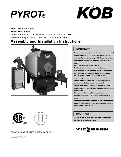
KOB Pyrot Installation & Operation
KOB Pyrot Installation & Operation
KOB Pyrot Installation & Operation

Create successful ePaper yourself
Turn your PDF publications into a flip-book with our unique Google optimized e-Paper software.
KRT 150 to KRT 540<br />
Wood Fired Boiler<br />
Maximum output: 150 to 540 kW / 512 to 1843 MBH<br />
Minimum output: 45 to 140 kW / 154 to 478 MBH<br />
Assembly and <strong>Installation</strong> Instructions<br />
KÖB IS A PART OF THE VIESSMANN GROUP.<br />
<strong>Pyrot</strong> ai/ii 11/2008<br />
IMPORTANT
Safety, <strong>Installation</strong> and Warranty Requirements<br />
Please ensure that’ these instructions are read and understood before commencing installation. Failure to comply<br />
with the instructions listed be low and detail sprinted in t hi s manual can cause product / property / damage, severe<br />
personal injury’, and / or loss of life. Ensure all requirements be low are understood and fulfilled (including<br />
detailed information found in manual subsections).<br />
� Licensed’ professional’<br />
heating contractor<br />
The installation, adjustment,<br />
service, and maintenance of this<br />
equipment must be performed<br />
by a licensed professional<br />
heating contractor.<br />
�" Please see section<br />
entitled “Important<br />
Regulatory and<br />
<strong>Installation</strong><br />
Requirements”.<br />
� Product documentation<br />
Read all applicable<br />
documentation<br />
before commencing installation.<br />
Store documentation near boiler<br />
in a readily accessible location<br />
for reference in the future by<br />
service personnel.<br />
�" For a listing of<br />
applicable literature,<br />
please see section<br />
entitled “Important<br />
Regulatory and Safety<br />
Requirements”.<br />
� Advice to owner<br />
Once the installation work is<br />
complete, the heating contractor<br />
must familiarize the system<br />
operator/ultimate owner with all<br />
equipment, as well as safety<br />
precautions/requirements, shutdown<br />
procedure, and the need<br />
for professional service annually<br />
before the heating season<br />
begins.<br />
� Contaminated air<br />
Air contaminated by chemicals<br />
can cause by-products in the<br />
combustion process which are<br />
poisonous to inhabitants and<br />
destructive to Viessmann<br />
equipment.<br />
�" For a listing of<br />
chemicals which cannot<br />
be stored in or near the<br />
boiler room, please see<br />
subsection entitled<br />
“Combustion air supply”<br />
� Carbon monoxide<br />
Improper installation,<br />
adjustment, service and/or<br />
maintenance can cause flue<br />
products to flow into living<br />
space. Flue products contain<br />
poisonous carbon monoxide<br />
gas.<br />
" For information<br />
pertaining to the proper<br />
installation, adjustment,<br />
service and maintenance<br />
of this equipment to<br />
avoid formation of carbon<br />
monoxide,<br />
please see instructions supplied<br />
with boiler.<br />
� Fresh air<br />
This equipment requires fresh air<br />
for safe operation and must be<br />
installed ensuring provisions for<br />
adequate combustion and<br />
ventilation air exist.<br />
�" For information<br />
pertaining to the fresh<br />
air requirements of this<br />
product, please see<br />
subsection entitled<br />
“Combustion air supply”.<br />
� Equipment venting<br />
Never operate boiler without an<br />
installed venting system. An<br />
improper venting system can<br />
cause carbon monoxide<br />
poisoning.<br />
�" For information<br />
pertaining to venting<br />
and chimney<br />
requirements, please<br />
see section entitled “Venting<br />
Connection”. All products of<br />
combustion must be safely<br />
vented to the outdoors.<br />
� Warranty<br />
Information<br />
contained<br />
In this and<br />
related<br />
product documentation must<br />
be read and followed. Failure<br />
to do so renders warranty<br />
null and void.<br />
2
Safety, <strong>Installation</strong> and Warranty Requirements<br />
� Fiberglass wool and ceramic<br />
fiber Materials<br />
The state of California has<br />
listed the airborne fibers of<br />
these materials as a possible<br />
cancer hazard through<br />
inhalation. When handling<br />
these materials, special care<br />
must be applied.<br />
Suppliers of ceramic fiber<br />
products recommend the<br />
following first aid measures:<br />
- Respiratory tract (nose and<br />
throat) irritation<br />
If respiratory tract irritation<br />
develops, move the person to<br />
a dust free location.<br />
- Eye irritation<br />
If eyes become irritated, flush<br />
immediately with large<br />
amounts of lukewarm water<br />
for at least 15<br />
minutes. Eyelids should be held<br />
away from the eyeball to<br />
ensure thorough rinsing. Do<br />
not rub eyes.<br />
- Skin irritation<br />
If skin becomes irritated,<br />
remove soiled clothing. Do not<br />
rub or scratch exposed skin.<br />
Wash area of contact<br />
thoroughly with soap and<br />
water.<br />
Using a skin cream or lotion<br />
after washing may be helpful.<br />
- Gastrointestinal irritation<br />
If gastrointestinal tract<br />
irritation develops, move the<br />
person to a dust free<br />
environment.<br />
Suppliers of fiberglass wool<br />
products recommend the<br />
following precautions<br />
be taken when handling these<br />
materials:<br />
Precautionary measures<br />
- Avoid breathing fiberglass<br />
dust and<br />
contact with skin and eyes.<br />
- Use NIOSH approved<br />
dust/mist respirator.<br />
- Wear long-sleeved, loose<br />
fitting clothing, gloves and eye<br />
protection.<br />
- Wash work clothes separately<br />
from other clothing. Rinse<br />
washerthoroughly.<br />
- <strong>Operation</strong>s such as sawing,<br />
blowing,<br />
tearout and spraying may<br />
generate<br />
airborne fiber concentration<br />
requiring<br />
additional protection.<br />
First aid measures<br />
- If eye contact occurs, flush<br />
eyes with<br />
water to remove dust. If<br />
symptoms<br />
persist, seek medical attention.<br />
- If skin contact occurs, wash<br />
affected<br />
areas gently with soap and<br />
warm<br />
water after handling<br />
� Hazardous materials<br />
3
Contents<br />
1 General Information 6<br />
1.1 State of the art 6<br />
1.2 Documented information 6<br />
2 Codes 6<br />
2.1 Mechanical room 6<br />
2.2 Working on the equipment 6<br />
2.3 Technical literature 6<br />
3 The structural Surroundings for the Furnace 7<br />
3.1 Heating room requirements 7<br />
3.2 The chimney connection 7<br />
4 Transport and <strong>Installation</strong> 7<br />
5 Water System <strong>Installation</strong> 8<br />
5.1 Safety Equipment 8<br />
5.2 Expansion 8<br />
5.3 The boiler circuit with return circuit 3- way valve 8<br />
5.4 The extinguishing water tank 8<br />
6 Electrical <strong>Installation</strong> 9<br />
6.1 Positioning the control cabinet 9<br />
6.2 Electrical connection 9<br />
7 Fire Protection 9<br />
7.1 Protection against burn-back for the boiler plant 9<br />
7.1.1 Preventing overfilling of the fire box 9<br />
7.1.2 Preventing burn-back 9<br />
7.1.3 The backflash safeguard (RZS) 9<br />
7.1.4 Automatically Triggering Extinguishing System for the Furnace Feed (SLEK) 9<br />
7.2 Burn-back safeguard for the fuel supply system (RSE) 10<br />
7.2.1 Automatically Triggering System for the Material Supply System (SLE-M) 10<br />
7.2.2 The slide valve 10<br />
7.2.3 Rotary valve 10<br />
7.2.4 Double rotary valve with pressure compensation system 10<br />
7.3 Fire protection for the fuel storage space 10<br />
8 Commissioning 10<br />
8.1 Filling the heating system 10<br />
8.2 Fuel for the commissioning 10<br />
8.3 Inspection of the installation 11<br />
8.4 Commissioning and handover 11<br />
4
9 Spec Sheets<br />
6960-1, 2, 3 PYROT rotary combustion chamber boiler, <strong>Installation</strong> of Closed System<br />
4550-1, 3 Extinguishing System, <strong>Installation</strong><br />
6010-1, 2, 3, 4 PYROT Rotation Heating System, Boiler Plant<br />
6110-1, 2 PYROT Rotation Heating System, Exhaust Gas Deduster<br />
6120-1, 2, 3 PYROT Rotation Heating System, De-ashing & Cleaning Systems<br />
6800-1, 2, 3 PYROT Rotation Heating System, Ecotronic Control System<br />
6810-1 PYROT Rotation Firing System, PYROT Double-boiler System<br />
6850-1, 2 Ecotronic Control System, PYROT Remote Transmission<br />
4000-1 ECOTRONIC Heating Control Unit, Equipping<br />
4020-1, 2, 3 ECOTRONIC Heating Control Unit, Module Extension, Data Transmission Lines<br />
4030-1, 2 ECOTRONIC Heat Control Unit, Additional Heat Generators<br />
4040-1, 2 ECOTRONIC Heat Control Unit, Heat Consumer<br />
4050-1, 2 ECOTRONIC Heating Control Unit, Solar Energy<br />
4090-1 ECOTRONIC Heating Control Unit, Visualisation & Remote Maintenance<br />
Supplement Arrangement of the electrical wiring on the PYROT<br />
1120-1, 2 Services and <strong>Installation</strong><br />
1010-1, 2 Wood Fuels, Minimum Requirements / Instructions<br />
1000-1, 2 General Terms and Conditions of Deliver<br />
5
1 General Information<br />
Viessmann solid-fuel boiler may only be set up and commissioned<br />
by specialists. This will rule out any incorrect<br />
assembly or commissioning. These instructions have thus<br />
been reduced to important technical data, references to<br />
regulations, technical rules and other regulations.<br />
Steel wood fired hot water heating boiler.<br />
For operation with modulating boiler water temperatures in<br />
closed and open loop forced circulation hot water heating<br />
systems.<br />
The <strong>Pyrot</strong> KRT boilers are certified the CAN/CSA B366.1-<br />
M91 and UL 391.<br />
The boiler model selected should be based on an accurate<br />
heat loss calculation of the building. The boiler selected<br />
must be complete with the connected radiation.<br />
Maximum working pressure 30 or 60 psig<br />
Maximum boiler temperature 250 °F / 121°C<br />
(closed loop)<br />
This boiler does not require a flow switch.<br />
1.1 State of the art<br />
The operating instructions are in keeping with the PYRTEC<br />
at the time of its delivery. In the interest of our customers,<br />
we reserve the right to make subsequent alterations resulting<br />
from further technical development without being required<br />
to give notification of such.<br />
1.2 Documented information<br />
The installation instructions contain the information required<br />
according to the subject boilers have been tested<br />
and examined in accordance with:<br />
CSA B366.1-M91<br />
Solid Fuel Fired Central Heating Appliances<br />
CSA C.22.2#3-M88(R2004)<br />
Electrical Features of Fuel Burning Equipment<br />
UL391 (4thEd)<br />
Solid Fuel and Combination-Fuel Central and Supplementary<br />
Furnaces<br />
CSA B365-01<br />
<strong>Installation</strong> Code for Solid Fuel Burning Appliances and<br />
Equipment<br />
2 Codes<br />
Please carefully read this manual prior to attempting<br />
installation. Any warranty is null and void if these<br />
instructions are not followed.<br />
For information regarding other Viessmann System<br />
Technology componentry, please reference<br />
documentation of the respective product.<br />
We offer frequent installation and service seminars to<br />
familiarize our partners with our products. Please inquire.<br />
The installation of this unit shall be in accordance with<br />
local codes. In the absence of local codes, use:<br />
CSA B365-0<br />
In Canada all electrical wiring is to be done in accordance<br />
with the latest edition of CSA C22.1 Part 1 and/or local<br />
codes. In the U.S., use the<br />
National Electrical Code ANSI/NFPA 70.<br />
2.1 Mechanical room<br />
Ensure the mechanical room complies with the<br />
requirements in this Viessmann recommends installation of<br />
an additional electrical disconnect switch and a fuel shutoff<br />
valve (if possible) outside the mechanical room or<br />
enclosed area of installation<br />
2.2 Working on the equipment<br />
A licensed professional heating contractor who is qualified<br />
and experienced in the installation, service, and maintenance<br />
of hot water boilers must do the installation, adjustment,<br />
service, and maintenance of this boiler.<br />
There are no user serviceable parts on the boiler, burners,<br />
or control.<br />
Ensure main power supply to equipment, the heating system,<br />
and all external controls have been deactivated. Take<br />
precautions in all instances to avoid accidental activation of<br />
power during service work.<br />
The completeness and functionality of field supplied electrical<br />
controls and components must be verified by the<br />
heating contractor. These include low water cut-offs, flow<br />
switches (if used),<br />
staging controls, pumps, motorized valves, air vents, thermostats,<br />
etc.<br />
2.3 Technical literature<br />
Literature for PYROT KRT boiler:<br />
- Assembly <strong>Installation</strong> Instruction<br />
- Operating and maintenance instructions<br />
- Field wiring diagram.<br />
Leave all literature at the installation site and advise the<br />
system operator/ultimate owner where the literature can be<br />
found. Contact Viessmann for additional copies.<br />
6
3 The structural Surroundings for the<br />
Boiler<br />
The national building regulations existing in this connection<br />
must always be complied with.<br />
3.1 Heating room requirements<br />
A separate, dry heating room must always be provided for<br />
the PYROT. No combustible materials may be stored in the<br />
heating room. The heating boiler may only be set up on a<br />
fire- and temperature-resistant floor. No temperaturesensitive<br />
pipes or lines may be installed in the floor below<br />
the heating boiler.<br />
The load-bearing capacity of the heating room floor must<br />
be designed for the weight of the system plus filling with<br />
water and fuel. The load-bearing capacity of the floor in<br />
the area of the boiler bearing surface must be (2000kg/m²)<br />
410lb/ft². Detailed technical dimensioning is possible with<br />
data sheet no. 6010.<br />
The minimum distance to the walls and ceiling required according<br />
to the table of dimensions for proper cleaning and<br />
maintenance of the boiler must be complied with. A sufficient<br />
supply of fresh air must be provided directly from<br />
outdoors into the heating room. Induced ventilation is<br />
necessary for heating rooms that are confined or enclosed.<br />
The temperature in the heating room must not exceed<br />
(+40°C) 104°F while the system is in operation (in the<br />
area approx. (1m) 3ft away from the boiler).<br />
The temperature in the heating room must not fall below<br />
(+10°C) 50°F while the system is in operation (inner side<br />
of exterior walls).<br />
3.2 The chimney connection<br />
The PYROT rotary combustion chamber boiler is equipped<br />
with an exhaust fan and thus a fireplace without a draught<br />
requirement.<br />
This boiler must be properly vented. Use a vent material<br />
certified for use with solid-fuel fired equipment.<br />
This boiler shall be connected to:<br />
a) a masonry chimney conforming to local regulations<br />
or, in the absence of such regulations, to the requirements<br />
of the National Building Code or<br />
b) a certified factory-built chimney.<br />
A flue pipe serving this boiler shall be constructed of steel<br />
or other suitable material with a melting point of not less<br />
than (1100°C) 2000°F.<br />
Galvanized steel shall not be used.<br />
For installations in the USA:<br />
The boiler venting system must be tested and listed<br />
by a Nationally Recognized Testing Lab to the UL<br />
103HT- Standard for Solid and Liquid Fuel Chimneys<br />
installed in the USA.<br />
For installations in Canada:<br />
The boiler venting system must be tested and listed<br />
by a Nationally Recognized Testing Lab to the ULC S-<br />
629- Standard for Solid and Liquid Fuel Chimneys<br />
installed in Canada.<br />
The PYROT rotary combustion chamber boiler is outputcontrolled<br />
within a range from 30%-100% of the rated<br />
boiler output. This produces exhaust temperatures within<br />
a range from min. (100°C) 212°F and max. (250°C)<br />
482°F. An insulated chimney should be provided to prevent<br />
the danger of sooting.<br />
The distance from the exhaust fan to the chimney should<br />
be as short as possible. 90° elbows should be avoided if<br />
possible. The flue gas pipes of more than (1 m) 3ft in<br />
length must be insulated.<br />
The connection to the chimney should be made such that it<br />
rises at an angle from 30°- 45°.<br />
The exhaust line, incl. the lead-in into the chimney, should<br />
be executed so as to be gas-tight.<br />
4 Transport and <strong>Installation</strong><br />
The personnel who carry out the transport have to know<br />
the dangers of accidents that might arise on doing so and<br />
prevent such through suitable measures.<br />
Only hoist the boiler when it is entirely empty (of water,<br />
fuel and ash).<br />
<strong>Pyrot</strong> 150 - 300<br />
Hoist by the lifting lug.<br />
<strong>Pyrot</strong> 400 - 540<br />
Hoist by forward-flow and return-flow connection pieces<br />
using a cross bar.<br />
WARNING – Follow instructions for proper installation.<br />
For fired installations:<br />
This boiler must be installed in accordance with local codes<br />
if any; if not, follow B 365-01, <strong>Installation</strong> Code for Solid-<br />
Fuel Burning Appliance and Equipment.<br />
This boiler need fresh air for safe operation and must be installed<br />
so there are provisions for adequate combustion and<br />
ventilation air.<br />
Inadequate supply of combustion air can cause poisonous<br />
flue gases to enter living space with can cause severe personal<br />
injury or loss of life.<br />
7
5 Water System <strong>Installation</strong><br />
Customers must ensure that there is a supply of water independent<br />
of the electricity supply. This (redundant) design<br />
ensures that in case of a power failure, the boiler will<br />
be reliably cooled by the thermal run-off safety valve.<br />
5.1 Safety Equipment<br />
The safety equipment for the heating installation must be<br />
carried out by the heating contractor authorised to do so.<br />
See Spec Sheet 5960 as an example.<br />
Installing safety devices on the boiler<br />
Installing safety devices.<br />
1. Install pressure relief valve, discharge pipe, air vent and<br />
pressure gage as described in the <strong>Installation</strong><br />
Instructions of safety header.<br />
A 30 or 60 psig pressure relief valve is shipped with the<br />
boiler (standard equipment).<br />
2. Install discharge pipe on pressure relief valve. The end<br />
of the pipe must not be threaded.<br />
The pressure relief discharge pipe should extend to a<br />
floor drain and end approximately 6”/150 mm above the<br />
drain.<br />
Do not install shut-off valve in discharge pipe.<br />
Do not reduce discharge pipe diameter.<br />
Do not pipe discharge to outdoors!<br />
IMPORTANT<br />
Install the (approved) factory supplied pressure relief valve.<br />
Removal of air from the system must occur via use of air<br />
vent(s) in the system supply. To ensure the boiler can be<br />
purged of all air, ensure supply/return water lines do not<br />
contain restrictive piping where air could be trapped.<br />
IMPORTANT<br />
This boiler does not require a flow switch.<br />
Low water cut-off<br />
A low water cut-off may be required by local codes.<br />
If boiler is installed above radiation level, a low water cutoff<br />
device of approved type must be installed in all<br />
instances. Do not install an isolation valve between boiler<br />
and low water cut-off.<br />
5.2 Expansion<br />
With closed expansion, the supply pressure to the expansion<br />
tank should be equal to the max. amount of the system<br />
pressure plus (0.2 bar) 3 psig.<br />
5.3 The boiler circuit with return circuit 3-<br />
way valve<br />
To reliably prevent boiler corrosion through condensation of<br />
the flue gases, the boiler return flow temperature must in<br />
no case be below 65°C 149°F.<br />
The PYROT rotary combustion chamber boiler is infinitely<br />
variably output-controlled. For that, it is necessary there to<br />
be a constant flow through the boiler of the water to be<br />
heated. The boiler circuit the boiler pump and boiler mixer<br />
must therefore be installed according to Spec Sheet 6960.<br />
The design of the boiler circuit should be carried out such<br />
that the temperature difference between the boiler supply<br />
and the Boiler return temperature is equal to or less than<br />
(15°C) 27°F.<br />
The activation of the boiler pump and boiler control valve is<br />
integrated in the custom control panel that comes with the<br />
boiler.<br />
5.4 The extinguishing water tank<br />
A self-activating extinguishing device must always be installed<br />
next to boiler feed system. With regard to the assembly,<br />
refer to the spec sheets in the annex<br />
The functioning is carried out by means of an extinguishing<br />
valve and is not dependent on electric current. A floattype<br />
switch monitors the water level and should be electrically<br />
connected (see connection diagram)<br />
8
6 Electrical <strong>Installation</strong><br />
6.1 Positioning the control module and<br />
control cabinet<br />
Electrical company at a place easily accessible for operation<br />
should mount the control module. Optimum positioning<br />
of the control cabinet will allow minimisation of the<br />
length of installation lines and thus of costs.<br />
The position of the control module and control cabinet<br />
should be selected such that the negative effect of heat<br />
radiation (front side of boiler, rear side of boiler with exhaust<br />
gas collector and exhaust gas fan as well as exhaust<br />
gas line) and interference caused by dust during cleaning<br />
will both be kept as low as possible.<br />
The ambient temperature for the control cabinet (approx.<br />
(10 cm) 4’’ away from the control cabinet) should not exceed<br />
(40°C) 104°F while the system is in operation. In<br />
case of doubt, preference should be given to placing the<br />
control cabinet outside the heating room near the heating<br />
room door.<br />
6.2 Electrical connection<br />
- Connect it according to the wiring plan, lying of the<br />
CAN-BUS wire according to data sheet 4020.<br />
- In the area of hot parts (flue gas fan, flue gas pipe), the<br />
lines should be installed in steel pipes at an appropriate<br />
distance so as to be temperature-protected.<br />
- The cable bushings to the motors and equipment must<br />
be executed so as to be dust-tight and provided with a<br />
strain relief.<br />
Attention:<br />
This is not complete system drawing. The installer has responsibility<br />
to assure that the control is suitable for the respective<br />
installation, and all necessary safety equipment is<br />
installed.<br />
Attention:<br />
The information about wire type, wire number and wire<br />
gauge, made in the wiring diagrams is not obligatory. The<br />
final decision of these settings has to be done by the executing<br />
installation company considering the local codes and<br />
regulations.<br />
7 Fire Protection<br />
The fire protection regulations for wood heating systems<br />
differ from country to country.<br />
The regulations applicable to the respective location of installation<br />
must always be complied with.<br />
7.1 Protection against burn-back for the<br />
boiler plant<br />
These are part of the scope of delivery for the PYRTEC<br />
Grate Firing System.<br />
7.1.1 Preventing overfilling of the fire box<br />
A level monitor must be installed to prevent overfilling of<br />
the firebox. The PYRTEC Grate Firing System has a light<br />
barrier to monitor the embers.<br />
7.1.2 Preventing burn-back<br />
With a sensor directly on the insertion pipe, any danger of<br />
burn-back beginning will be detected and quickly counteracted<br />
at an early stage through boosted output (an increase<br />
in the advancing of the material).<br />
As a result, any requirement for a protective device coming<br />
into effect is avoided, and normal operation, defined as the<br />
greatest possible degree of safety supplying heat, is adhered<br />
to.<br />
7.1.3 The back flash safeguard<br />
The back flash safeguard is over 150 kW.<br />
The PYROT Grate Firing System is always equipped with<br />
an isolating layer and is continuously operated with negative<br />
pressure.<br />
As a result the PYROT Grate Firing System is considered as<br />
equipped with a back flash safeguard.<br />
7.1.4 Boiler Feed Automatically Triggering Extinguishing<br />
System.<br />
A water extinguishing system is always necessary on the<br />
feed auger.<br />
This system should reliably prevent burn-back in case of a<br />
malfunction (such as a power failure). For safety reasons<br />
and to prevent damage by flooding, connecting the<br />
extinguishing system directly to the water network is not<br />
advisable.<br />
This extinguishing system must always be equipped with a<br />
6.6 USG / 25l extinguishing water tank with a float-type<br />
switch and an adjustable Danfoss extinguisher valve. The<br />
tank for the SLE must be equipped with a level monitoring<br />
system.<br />
If there is a shortage of water, the PYROT Grate Firing System<br />
will switch off automatically. In case of excess temperature,<br />
the feed auger will be flooded reliably but in a<br />
limited fashion.<br />
The heating contractor according to Spec Sheet 4550 must<br />
carry out the piping for the extinguishing system.<br />
7.2 Burn-back safeguard for the fuel supply<br />
system (RSE)<br />
The rest of the "burn-back protection for material transport"<br />
depends on the respective requirements (location,<br />
size of the fuel storage site, material, pressure conditions<br />
9
and regulations) these being separate items for the scope<br />
of delivery ordered from Viessmann according to the descriptions<br />
below.<br />
We always recommend installing a rotary valve as<br />
per section 7.2.3 for the PYROT Rotation Heating<br />
System.<br />
In addition to being a safeguard against burn-back,<br />
this will also prevent any penetration by air leaking in<br />
via the feed auger.<br />
7.2.1 Automatically Triggering System for the Material<br />
Supply System (SLE-M)<br />
Approved in part as a variation to the shut-off valve in<br />
pressure-less fuel storage units.<br />
The heating engineer according to Spec Sheet 4550<br />
must carry out the installation of the extinguishing<br />
system.<br />
7.2.2 The slide valve<br />
This is approved in pressure-less fuel storage units in all<br />
cases and suitable safeguard against back-burn.<br />
7.2.3 Rotary valve<br />
If remnant wood is moved into fuel storage spaces with<br />
fans, then, in order to reduce pressure applied, at least one<br />
rotary valve is necessary to reduce pressure between the<br />
fuel storage unit and the furnace. The rotary valve is<br />
A smoke gas alarm must be installed between the rotary<br />
valve and the silo extraction system, which, when triggered,<br />
will disconnect the system causing the negative<br />
pressure for the silo.<br />
7.3 Fire protection for the fuel storage space<br />
The measures necessary for this are never part of the<br />
scope of performance from Viessmann.<br />
The conditions set by the local building authorities must be<br />
met by the operating organisation in this connection.<br />
8 Commissioning<br />
Only Viessmann or another trained specialist may put a<br />
newly installed facility into operation for the first time.<br />
Before the facility is commissioned, the system must be<br />
filled with water, fuel stored for the commissioning and the<br />
installation inspected.<br />
8.1 Filling the heating system<br />
The first filling is usually carried out with untreated water<br />
without any chemical water treatment but definitely filtered<br />
and thus free of any suspended solids.<br />
Pay special attention when the filling is carried out to be<br />
sure the air is carefully bled out. With difficult water conditions<br />
(high degrees of hardness, etc) and/or large vol-<br />
suited to reduce pressure and at the same time is consider<br />
as a suitable safeguard against back-burn.<br />
Max. overpressure allowed in fuel storage unit:<br />
(+500 Pa) +2.00"wc.<br />
Max. negative pressure allowed in fuel storage unit:<br />
(+0 Pa) +0"wc.<br />
7.2.4 Double rotary valve with pressure compensation<br />
system<br />
If, due to special circumstances, any mechanically produced<br />
negative pressures or extraordinarily high overpressures<br />
are expected in the fuel storage unit, then two rotary<br />
valves must be installed in the material transport route according<br />
to the respective project plan with a pressure compensation<br />
line to the outdoors.<br />
Maximum overpressure allowed in fuel storage unit:<br />
(+3000 Pa) /+12"wc.<br />
Maximum negative pressure allowed in fuel storage<br />
unit: (-3000 Pa) / – 12"wc.<br />
One must have the supplier of the chip suctioning system<br />
confirm the maximum pressures to be expected.<br />
The rotary valve below the silo extraction system can become<br />
leaky due to wear of the sealing elements or through<br />
large pieces of wood that cannot be conveyed. This leakage<br />
can make it possible for low-temperature gases to flow<br />
back from the furnace into the silo.<br />
umes of water by using appropriate measures for water<br />
treatment.<br />
Note: The filling pressure of the cold water reserve should<br />
be approx. (0.1 bar) 1.5 psig greater than the supply pressure<br />
of the closed expansion tank.<br />
8.2 Fuel for the commissioning<br />
For the commissioning, dry fuel (max. W 20%) should be<br />
stored in an amount for approx. 10-24 full operating hours.<br />
This is as follows:<br />
PYROT 100 approx. 1760 lb<br />
PYROT 150 approx. 2640 lb<br />
PYROT 220 approx. 3300 lb<br />
PYROT 300 approx. 4400 lb<br />
PYROT 400 approx. 5500 lb<br />
PYROT 500 approx. 6600 lb<br />
Since the boiler plant is cold, and the residual moisture will<br />
also be drawn from the refractory concrete during the initial<br />
operation, the material to be burned for the initial operation<br />
has to be at least air dry. The heating-up process<br />
should be carried out during the first three hours at low<br />
output.<br />
To check the functioning of the silo extraction system, not<br />
too much material to be burned should be stored so as to<br />
be able to quickly clear out the extraction system to remedy<br />
the cause of any malfunction there might be.<br />
10
8.3 Inspection of the installation<br />
Before the commissioning, the future operating organisation<br />
along with the installing companies (heating contractor<br />
& electrician) are obliged to inspect the installation for the<br />
following points:<br />
1. Exhaust gas port connected to the exhaust gas line on<br />
the chimney.<br />
2. Chimney completely installed with clear cross section<br />
all the way through.<br />
3. Safety valve installed on the boiler and/or boiler forward<br />
flow.<br />
4. Thermal run-off safety valve connected to the cold<br />
water network.<br />
5. The sensor for the thermal run-off safety valve is situated<br />
in the dipping shell.<br />
6. The sensor for the temperature-limiting safety switch<br />
is situated in the dipping shell.<br />
7. The extinguishing water tank on the feed auger is<br />
filled with water.<br />
8. The sensor for the extinguisher valve is mounted tight<br />
on the pipe for the feed auger.<br />
9. The expansion tank is connected.<br />
10. The conveying systems are installed between the<br />
boiler and the material storage unit.<br />
11. The facility is filled with water.<br />
12. Material to be burned is stored for the test operation.<br />
13. The safety limit switch is installed on the door to the<br />
material storage site (if there is a walk-through door).<br />
14. The control system is connected to the power supply<br />
network.<br />
15. The motors, switches and sensors are electrically<br />
connected.<br />
Do not put the boiler plant into operation over-hastily without<br />
the presence of a specialist from Viessmann or another<br />
trained specialist.<br />
In case of damage, you would lose your warranty claims.<br />
Inspected on . . . . . . . . . . . . . . . . . . . . . . . . . . . .<br />
By . . . . . . . . . . . . . . . . . . . . . . . . . . . . . . . . . . . . .<br />
Signature . . . . . . . . . . . . . . . . . . . . . . . . . . . . . .<br />
8.4 Commissioning and handover<br />
A competent contact person from the operating organisation's<br />
side must be present for the commissioning and<br />
handover.<br />
The heat dissipation from the boiler plant has to be assured<br />
by the operating organisation or by the heating engineer.<br />
The heating contractor has to confirm that an inspection of<br />
the installation has been carried out positively by handing<br />
over these signed <strong>Installation</strong> Instructions.<br />
Complying with these <strong>Installation</strong> Instructions and also following<br />
the Operating Instructions, you will be provided<br />
with heat from wood in a safe and convenient fashion.<br />
Viessmann Manufacturing Company Inc. thanks you for the<br />
trust you have shown in us.<br />
These <strong>Installation</strong> Instructions should be kept near the facility<br />
on a permanent basis.<br />
11
Notes<br />
12
Spec Sheet<br />
<strong>Pyrot</strong> Rotation Heating System<br />
<strong>Installation</strong>, closed system<br />
vIESmAnn<br />
6960-1
a) Note:<br />
- To reliably prevent boiler corrosion caused by condensation of flue gases, the boiler return flow temperature must<br />
not under any circumstances be below 150°F/65°C. A boiler circuit pump with a boiler mixer should be provided according<br />
to the diagram for this purpose. The boiler circuit should be designed such that the temperature difference between<br />
the forward flow and the return flow is equal to or less than ∆t 15°C / 27°F.<br />
- For integrating heat consumers, see Spec Sheet 4000.<br />
- The expansion tank has to be connected to the boiler above the boiler forward flow and without any shut-offs.<br />
b) Safety-relevant equipment included in the scope of performance provided by the installing<br />
heating engineer<br />
M 20 Boiler pump<br />
Y 20 Boiler mixing valve<br />
SV Safety valve, pressure set to max. 3.0 bar, homologated component as per DIN 3440<br />
Nominal width of the valve, of the connection line and of the exhaust pipe as per DIN 4751 Part 2<br />
TS131 Thermal run-off safety valve R ¾”, homologated component; special-purpose design for opening<br />
temperature 212°F/ 100°C, (safety heat exchanger built into boiler). With the <strong>Pyrot</strong>-400 and <strong>Pyrot</strong>-540, two safety<br />
heat exchangers in parallel are required but only one thermal run-off safety valve.<br />
KW. Cold water inlet, min. 36 psig/ 2.5 bar, max. 51 psig/ 3.5 bar<br />
WMS... Water level control device, homologated component; required in Germany starting from systems over 350<br />
KW, <strong>Installation</strong> recommendation: WMS with magnetic transmission of the float movement to a switch unit<br />
EL Air separator (recommendation: absorption-type degasser)<br />
ExH... Expansion tank closed, with design certification; for heating system (Recommendation: connect on cool return flow,<br />
connected to the boiler via the forward flow without any blockage units)<br />
ExS… Expansion tank closed; with design certification; for safety heat exchanger, max. 4.0 liters, 145 psig/ 10 bar<br />
DAZ Pressure indication device (pressure gauge)<br />
TAZ Temperature indication device (thermometer)<br />
c) Design recommendation<br />
Model<br />
KRT<br />
Boiler circuit<br />
(VL, RL,BP)<br />
Thermal<br />
run-off<br />
safety valve<br />
TS-131<br />
(Quantity)<br />
Water<br />
through-put<br />
required at<br />
2.5 bar<br />
/36 psig<br />
l/h GPM<br />
Spec Sheet<br />
<strong>Pyrot</strong> Rotation Heating System<br />
<strong>Installation</strong>, closed system<br />
Storage tank<br />
(accumulator)<br />
Volume³)<br />
L USG<br />
Supply<br />
line ZL<br />
Drain pipe<br />
AL²)<br />
Safety relief<br />
valve<br />
Watts or<br />
Conbraco<br />
30Lb or 60Lb<br />
Safety<br />
line<br />
SL²)<br />
150 NW 50 1 915 4 1500 396 R¾" R 1" ¾" ¾" NW 40<br />
220 NW 50 1 1230 5.4 2200 581 R¾" R 1" ¾" ¾" NW 40<br />
300 NW 65 1 1500 6.6 2500 660 R¾" R 1" 1" 1" NW 50<br />
400 NW 80 1 1880 8.3 3200 845 R¾" R 1" 1" 1" NW 50<br />
540 NW 60 1 2266 10 4300 1136 R¾" R 1" 1¼" 1¼" NW 65<br />
1) Threaded connection for supply line<br />
2) Length of the exhaust pipe up to 4.0 m 13ft (for longer lines, see DIN 4751 Part 2)<br />
3) On request, we will be glad to provide a project-based offer on the storage tanks(s).<br />
d) Equipment recommendation from Viessmann delivery program<br />
- Note: The equipment below will only be supplied via the installing heating engineer<br />
North America<br />
Boiler model<br />
KRTpump<br />
freq.<br />
voltage<br />
and<br />
phase<br />
Grundfos<br />
part<br />
number<br />
Vi. Part<br />
Number<br />
voltage<br />
and<br />
phase<br />
Grundfos<br />
Vi. Part<br />
part<br />
number<br />
number<br />
150 UPS 32-80 F 60 Hz 3 x 208-230 V 96402710 9560240 1 x 230 V 96402709 9560239<br />
220 UPS 40-80/4 F 60 Hz 3 x 208-230 V 96404950 9544478 1 x 230 V 96404949 9560255<br />
300 UPS 50-80/4 F 60 Hz 3 x 208-230 V 96404960 9560274 1 x 230 V 96404959 9560273<br />
400 UPS 50-80/4 F 60 Hz 3 x 208-230 V 96404960 9560274 1 x 230 V 96404959 9560273<br />
540 UPS 50-80/4 F 60 Hz 3 x 208-230 V 96404960 9560274 1 x 230 V 96404959 9560273<br />
1) For ∆t 15K, 27°F as per illustration<br />
Any additional resistors (heat meters, slide valve) require redesigning of the boiler pump!<br />
vIESmAnn<br />
6960-2
Mixing valves:<br />
North America<br />
Spec Sheet<br />
<strong>Pyrot</strong> Rotation Heating System<br />
<strong>Installation</strong>, closed system<br />
boiler model 3-way mixing valve mixing valve actuator<br />
KRT- diameter Viessmann Viessmann<br />
part no. part no.<br />
150<br />
220<br />
2" 7133024 7133390<br />
300 2½" Z001194 (Centra)<br />
400<br />
540<br />
3" Z001195 (Centra)<br />
9544483 (Centra)<br />
vIESmAnn<br />
6960-3
a) Fire-extinguishing System for Burner Slide-in Module, Art. No. K-SLE<br />
Note: Pyromat-DYN has an extra charge with Art. No. K-SLE (see Spec Sheet 4500)<br />
With <strong>Pyrot</strong> and Pyrtec this is included in the burner article.<br />
Fig. 1: K-SLE on feed auger<br />
Spec Sheet<br />
Fire- extinguishing Systems<br />
K-SLE & K-SLV <strong>Installation</strong><br />
b) Fire-extinguishing System for Material Feed Facility, Art. No. K-SLV<br />
For Köb scope of delivery, refer to Spec Sheet 4500<br />
vIESmAnn<br />
4550-1<br />
Fig. 2: K-SLV on conveyor auger Fig. 3: K-SLV on extractor system situated on top with<br />
Down pipe<br />
Be sure to note:<br />
· The lines must be executed in metal (1/2") with fixed pipe work (K-SLE and K-SLV).<br />
· It must not be possible to shut off the cold water inlet without the aid of tools.<br />
· Be especially sure to comply with Point 5 of the <strong>Installation</strong> Instructions (Fire Prevention).<br />
Note:<br />
K-SLV is an alternative or supplementary safety device. As standard, either a slide valve (Art. No. MBA-.; included in<br />
Article ADF_.,. / ADE_3,0) is required for pressure less material storage sites or a rotary valve (Art. No. MBZ-.) for<br />
material storage sites with over- or under-pressure (loading with fan, such as wood-processing businesses).
Spec Sheet<br />
Fire- extinguishing Systems<br />
K-SLE & K-SLV <strong>Installation</strong><br />
vIESmAnn<br />
4550-2
Spec Sheet<br />
Fire- extinguishing Systems<br />
K-SLE & K-SLV <strong>Installation</strong><br />
vIESmAnn<br />
4550-3
Description:<br />
The PYROT Rotation Heating System (patent no: EP 0 905 442 B1) was developed for automatic incineration of all dry<br />
to moist wood fuels (remnant wood, pellets and forest woodchips to max. W35-40).<br />
The PYROT Rotation Heating System is characterized by high efficiencies and perfect incineration at all load levels. The<br />
PYROT Boiler Plant has been tested and approved in accordance with the latest quality criteria as per EN 303-5 Heating<br />
Boilers for solid fuels, CE-certification in accordance with European Machinery Directive with continuous quality<br />
inspection by the TÜV.<br />
Max. forward flow temperature allowed: 250°F / 121°C<br />
Max. operating pressure allowed: 30 or 60psig<br />
Safety heat exchanger: Built into the boiler<br />
Spec Sheet<br />
<strong>Pyrot</strong> Rotation Heating System<br />
Boiler plant<br />
How it functions:<br />
- The feed auger conveys the material to be burned diagonally from below into the firing system. The holding devices<br />
for the burn-back sensor and the thermal extinguishing valve are situated on the conveyor pipe. Above the auger,<br />
there is a metering container with a light barrier to ascertain the level of the fuel isolating layer required according to TRD 414.<br />
- The material to be burned is ignited automatically by an electric heat gun. The gasification of the fuel is carried out on<br />
a feed grate moved by a worm-geared motor. The ash falls in an ash bin below. An automatic de-ashing system is<br />
optional. The fire block is lined with highly refractory insulation and fired refractory concrete elements.<br />
- The combustion gases rising from the fire block are swept up by the rotating secondary airflow brought to bear by the<br />
rotation blower and burned out completely in the round combustion chamber. The thermal energy from the<br />
combustion gases is transmitted to the boiler water in a horizontally positioned pipe-type heat exchanger. The boiler<br />
is heavily insulated, cased in an aesthetically pleasing fashion and provided with excellent access through the boiler<br />
door on the end side. On the rear side of the boiler there is a flange for an oil burner, which is closed by an insulated<br />
blank lid with an inspection window.<br />
- A flue gas re circulation system reduces the temperature in the fire box while maintaining the highest possible degree<br />
of efficiency. This increases the service life of the un-cooled refractory elements in the incineration zone. With the<br />
basic setting, the ratio of re-circulated gas to fresh air is geared precisely to the material to be burned. A mechanical<br />
flow volume regulator provides a constant ratio of the quantity of re-circulated gas to fresh air over the entire output range.<br />
- The flue gas fan is specially designed for wood heating operation and is very quiet. The motor has a solid, heat resistant<br />
design with a heat dissipation hub and is spring-supported. The fan casing on the intake port turns in infinitely variable fashion.<br />
The blow-out nozzle is round. <strong>Installation</strong> is possible on the top, side or rear of the flue gas collector. Included in the delivery:<br />
- Feed auger with isolating layer, incl. extinguishing valve with dirt trap, extinguishing water container with holding device<br />
- Fire block with feed grate<br />
- Automatic ignition device<br />
- Boiler with rotation combustion chamber<br />
- Set of displacement rods<br />
- Flue gas re-circulation system<br />
- Exhaust fan<br />
- Supplementary air device (draught controller); for installation in the exhaust pipe<br />
- Accessories: counter-flange, incl. bolts, seals and cleaning device<br />
Requirements on the chimney:<br />
<strong>Installation</strong> of a supplementary air device (draught controller) if not possible in the fire tube (see Spec Sheet 6010-3).<br />
ACCESSORIES for PYROT Rotation Heating System (Item KRT-...) at extra charge:<br />
vIESmAnn<br />
6010-1<br />
Designation Item Text Dimensions Use<br />
Exhaust gas de-duster 90 l KRT-E...1 6110 6110 Optional<br />
De-ashing in bin, 240 l KRT-A2-S 6120 6120 Optional (standard)<br />
De-ashing in skip, 800 l KRT-A8-S 6120 Variation for KRT-A2-S<br />
De-ashing in base container KRT-ES-...-S 6120 6120 Variation for KRT-A2-S<br />
Cleaning system, pneumatic KRT-W...-S 6120 6120 Optional<br />
Operating pressure of 6 bar allowed KRT-P.. 6200 Customized design from PYROT 220<br />
Feed auger, two-stage , KRT-P2 6200 Optional (switchover: pellets to chips)<br />
Insulation for re circulated flue gas line DN 80 KRT-RZ-IS1 6200 Advisable (or insulation by customer)<br />
Insulation for re circulated flue gas line DN 125 KRT-RZ-IS2 6200 Advisable (or insulation by customer)<br />
Reduced output: KRT- VS-… 6200 Optional (reduced charge)<br />
Ecotronic control system ECO-... 6800 Required
Technical specs:<br />
Spec Sheet<br />
<strong>Pyrot</strong> Rotation Heating System<br />
Boiler Plant<br />
PYROT Rotation Heating system<br />
vIESmAnn<br />
6010-2<br />
Trade name 150 220 300 400 540<br />
Item No:<br />
Performance data<br />
KRT-150 KRT-220 KRT-300 KRT-400 KRT-540<br />
Related heat output QN MBH / [kW] 512 / 150 751 / 220 1024 / 300 1365 / 400 1843 / 540<br />
Continuous output 1) QD MBH / [kW] 461 / 135 683 / 200 921 / 270 1229 / 360 1639 / 480<br />
Minimum heat output2) Qmin MBH / [kW] 154 / 45 205 / 60 273 / 80 341 / 100 478 / 140<br />
Efficiency in operation to be performed [%] 85%<br />
Maximum water content 3) [%] W 40<br />
Size of the chips 4) Exhaust gas figures<br />
G 30 / G 50 as per CAN/CSA-B366. 1-M91<br />
Mass flow rate QN; W5; O2 6% [lb/s] [g/s] 80.4 117.9 160.8 214.4 289.44<br />
Volume flow QN; W5; O2 6%; 150ºC [ft³/s][ m³/s] 3.1 / 0.09 4.9 / 0.14 6.7 / 0.19 8.8 / 0.25 12.4 / 0.35<br />
Mass flow rate QW35; W35; O2 8%; [g/s] 106.9 156.9 213.9 285.2 385.1<br />
Volume flow QW35;W35; O2 8%; 150°C [m/s] 0.12 0.19 0.25 0.34 0.46<br />
Average exhaust gas temperature at QN5) [°F /°C] 320 / 160<br />
Average exhaust gas temperature at QMIin5) [°F /°C] 266 /130<br />
Chimney drought required [Pa]<br />
Electrical connections<br />
±0<br />
Electrical connections, total [kW] 2.67 2.85 3.6 3.98 3.63<br />
Ignition device [kW] 1.6<br />
Flue gas fan [kW] 0.55 0.55 0.75 1.1 1.1<br />
Articulated head fan [kW] 0.12<br />
Feed auger [kW] 0.37 0.55 1.1 1.1 0.75<br />
Grate drive unit [kW] 0.03 0.03 0.03 0.06 0.06<br />
Electric power consumption at QN [kW] 1.032 1.108 1.521 1.868 1.753<br />
Electric power consumption at Qmin [kW]<br />
Heating – relevant specs<br />
0.355 0.369 0.434 0.480 0.460<br />
Volume on heating gas side [ltr] 374 744 883 1340 1613<br />
Volume of ash container for grate ash [ltr] 32 45 55 75 91<br />
Volume opf ash container for flue gas [USG / ltr]<br />
de-duster<br />
24 / 90<br />
Water side resistance (diff.15 K / 27°F) [“wc/mbar] 13 / 38 30 / 76 16 / 42 11 / 29 22 / 56<br />
Boiler water volume [USG / ltr] 114 /432 209 / 794 238 / 903 350 / 1326 399 / 1510<br />
Heating surface [ft² / m²] 116 / 1.078 173 / 16.04 115 / 20.72 310 / 28.76 424 / 39.36<br />
Test pressure 6) [psig / bar] 173 / 5<br />
Maximum operating pressure 6) [psig / bar] 30 or 60 / 2 or 4<br />
Maximum boiler operating pressure [°F /°C] 212 / 100<br />
Minimum return temperature [°F /°C]<br />
Weights<br />
149 / 65<br />
Weights of fire block [lb / kg] 906 / 412 1084 / 493 1251 / 569 1590 / 723 1648 / 794<br />
Weight of heat exchanger 7) [lb / kg] 3201 / 1455 5031 / 2287 5970 / 2714 8690 / 3950 9541 / 4337<br />
Weight of flue gas de-duster [lb / kg] 649 /295 693 /315 693 /315 770 /350 770 /350<br />
Weight of feed auger [lb / kg] 277 / 126 277 / 126 277 / 126 282 / 128 282 / 128<br />
Total weight without water 8) [lb / kg] 5034 / 2288 7086 / 3221 8193 / 3724 11332 / 5151 12340 / 5609<br />
Total weight with water 8) [lb / kg] 5984 / 2720 8833 / 4015 10179 / 4627 14249 / 6477 15662 / 7119<br />
1) Continuous output: Output leveling out as base load boiler in continuous operation with pneumatic cleaning<br />
system (for track time, see Operating Instructions)<br />
2) Q Qmin : <strong>Operation</strong> with modulated control (Infinitely variable power control)<br />
Q ! Qmin : Low load with ON Qmin / OFF (Stop-and-go mode)<br />
3) Moist fuels: >W35 further limitations regarding output, degree of efficiency and control behavior<br />
4) Specification: See Spec Sheet 1010, Minimum Requirements for Wooden Fuels<br />
5) Exhaust gas temperature: An increase is possible by removing the displacement rods (QN + 30°C; Qmin + 10°C)<br />
Other influences: Fuel, water content, ash content, pneumatic cleaning system yes/no;<br />
track time (number of operating hours without cleaning)<br />
Specifications for the start of the track time (toward the end of the track time there is an<br />
increase in the exhaust gas temperature by approx. 20°C)<br />
6) At extra charge: 7.8 bar test pressure; 6 bar operational pressure;<br />
7) Weights: Incl. door and refractory concrete lining<br />
8) Total weight: Incl. displacement rods
Spec Sheet<br />
<strong>Pyrot</strong> Rotation Heating System<br />
Boiler Plant<br />
vIESmAnn<br />
6010-3
Spec Sheet<br />
<strong>Pyrot</strong> Rotation Heating System<br />
Boiler Plant<br />
vIESmAnn<br />
6010-4<br />
Connections / dimensions:<br />
Ptrtec [Item-Nr.]<br />
Water connection PN 6 (see Spec Sheet 6960)<br />
KRT-150 KRT- 220 KRT-300 KRT-400 KRT-540<br />
l Boiler forward flow R 2” F 3”/ DN 80 3”/ DN 80 4”/DN 100 4”/DN 100<br />
PN6<br />
PN6<br />
PN6<br />
PN6<br />
ll Boiler return flow R 2” F 3”/DN 80 PN6 3”/DN 80 PN6 4 /DN 100 PN6 4“DN 100 PN6<br />
lll Connection for extinguishing water R 3 /4"<br />
lV Drain valve for boiler 2 x R 1 /2"M 2 x R 1 /2"M 2 x R 1 /2"M 4 x R 1 /2"M 4 x R 1 /2"M<br />
V Safety heat exchanger 2 x R 1 /2"F<br />
Vl Dipping shell for thermal run off safety<br />
Connection exhaust flue gas pipe ¯ [in / mm] A 97 /8"/ 250 97 /8"/ 250 117 /8"/ 300 137 /8"/ 350 137 /8"/ 350<br />
Location of the connections [in / mm] b 60.6 / 1541 60 /1525 73.8 / 1875 70.8 / 1800 80 /2030<br />
Dimension of the foundations [in / mm] d 112.2 / 2850 123.2 / 3130 142.2 / 3613 147.1 / 3738 161.5 / 4103<br />
f 29.1 / 740 29.1 / 740 34.6 / 880 37.8 / 960 43.1 / 1059<br />
g 20.5 / 520 20.5 / 520 28.3 / 723 17.6 / 448 21.3 / 543<br />
h 61.8 /1570 80.7 / 2050 80.7 / 2050 96.8 / 2460 96.8 / 2460<br />
i 24.4 / 620 26.7 / 680 26.7 / 680 31.5 / 800 31.5 / 800<br />
Dimensions of the boiler B 34.25 / 870 45.25 / 1150 45.25 / 1150 54.7 / 1390 54.7 / 1390<br />
C 26.5 / 673 26.5 / 673 26.5 / 673 26.5 / 673 29.5 / 750<br />
D 75.6 / 1920 86.5 / 2200 86.5 / 2200 96 / 2440 96 / 2440<br />
E 122.8 / 3120 134.8 / 3424 148.8 / 3780 157.6 / 4004 166.6 / 4232<br />
F 34.25 / 870 45.25 / 1150 42.25 / 1150 54.75 / 1390 54.75 / 1390<br />
G 14.6 / 370 14.6 / 370 17.3 / 440 17.3 / 440 24.6 / 548<br />
I 3” / DN 80 3” / DN 80 5” / DN 125 5” / DN 125 5” / DN 125<br />
K 75 / 1908 85.3 / 2168 86 / 2182 96.7 / 2457 99.5 / 2527<br />
L 69.5 / 1765 79.6 / 2024 79.6 / 2024 89 / 2262 91.8 / 2332<br />
M 71.8 / 1825 82 / 2084 82 / 2084 95.3 / 2422 (1) 98.1 / 2492 (1)<br />
O 27.5 / 700 27.5 / 700 27.5 / 700 27.5 / 700 29.2 / 742<br />
Q 27.5 / 700 35.4 / 900 35.4 / 900 43.3 / 1100 43.3 / 1100<br />
R 88.5 / 2250 89.5 / 2274 103.5 / 2630 103 / 2614 111.9 / 2842<br />
S 119.5 / 3035 120.4 / 2059 134.5 / 3415 136.1 / 3457 145 / 3685<br />
T 15.5 / 392 16 / 406 16 / 406 18.3 / 466 18.3 / 466<br />
U 14 / 358 14 / 358 13.8 / 352 14.75 / 375 14.75 / 375<br />
W 11.5 / 292 11.5 / 292 12.7 / 323 12.7 / 323 17.4 / 442<br />
X 9.1 / 232 10.1 / 257 10.9 / 277 14 / 355 14 / 355<br />
Y 43 / 1093 46.4 / 1179 46.4 / 1179 48 / 1219 48 / 1279<br />
Z 11.9 / 303 12.5 / 316 12.5 / 316 12.6 / 319 12.6 / 319<br />
1) With <strong>Pyrot</strong> 400/5540: Suspension gear is detachable.<br />
Parts for maintenance<br />
1 Boiler door with rotation fan<br />
2 Ash doors for the grate ash (2 units)<br />
3 Maintenance cover for firing block<br />
4 Cleaning lid for exhaust gas collector<br />
5 Pneumatic cleaning system Item KRT-W…-S Speck Sheet 6120<br />
6 Re-circulated flue gas line, variable arrangement of line<br />
Electric drives & ignition<br />
7 Feed auger<br />
8 Drive and feed grate<br />
9 Ignition device<br />
10 Exhaust fan<br />
11 Articulated head fan<br />
12 De ashing system for fire block Item KRT-E.-S / Spec Sheet 6120<br />
13 De-ashing system for ascending conveyor auger Item KRT-E.-S / Spec Sheet 6120<br />
Switches and sensors These items are part of the Ecotronic control system Item PRT-… / Spec Sheet 6800<br />
14 Light barrier for feed auger<br />
15 Limit switch for maintenance cover<br />
16 Temperature sensor for feed auger<br />
17 Light barrier for embers (2 units)<br />
18 Light barrier for de-ashing<br />
19 Boiler sensor<br />
20 Return flow sensor<br />
21 Temperature-limiting safety switch (STB)<br />
22 Exhaust gas sensor Location: Spec Sheet 6010<br />
23 Lambda sensor with measuring transducer Location: Spec Sheet 6010
Description:<br />
Exhaust gas de-duster 90 liters [24 USG], [Item no. KRT-E…-1]<br />
The exhaust gas de-duster is for minimizing dust emissions and is executed as a multi-cyclone with an axial function. The<br />
De-duster is completely insulated, attractively encased and provided with three lids for cleaning. The crude gas space is<br />
cleaned via the cleaning lid on the side. The clean gas chamber is cleaned via the top or rear cleaning lid (fan<br />
connection not used).<br />
The ash container, which is provided with a trolley, connects to the de-duster by quick-action fasteners and moves out<br />
simply for emptying. The exhaust fan (see description of PYROT) is mounted either on top or on the side, as desired.<br />
Note: The exhaust gas de-duster is required for the PYROT with fuels with high amounts of fine particles.<br />
(Woodworking businesses, forest woodchips with fine particles amounting to more than 4%)<br />
One ash bin comes with the system.<br />
Additional ash bins have to be ordered separately.<br />
Ash Bin, 90 liters [24 USG], reserve [Item No. EB-90]<br />
Spec Sheet<br />
<strong>Pyrot</strong> Rotation Heating System<br />
Exhaust Flue gas De duster<br />
vIESmAnn<br />
6110-1
Dimensions and data:<br />
Spec Sheet<br />
<strong>Pyrot</strong> Rotation Heating System<br />
Exhaust flue gas De duster<br />
vIESmAnn<br />
6110-2<br />
Exhaust flue gas de-duster PYROT [ITEM NO] KPR-E150-1 KPR-300-1 KPR-E400-1 KPR-E540-1<br />
A [in] / [mm] 7.9 / 200 9.8 / 250 11.8 / 300 11.8 / 300<br />
a [in] / [mm] 59.8 / 1521 63.8 / 1621 65.8 / 1671 68.5 / 1741<br />
c [in] / [mm] 59.7 / 1518 69.9 / 1775 73.8 / 1875 76.7 / 1949<br />
j [in] / [mm] 92 / 2338 103.7 / 2643 111.6 / 2835 115.3 / 2930<br />
k [in] / [mm] 33.5 / 850 33.5 / 850 33.5 / 850 36.2 / 920<br />
l [in] / [mm] 35.3 / 898 45.5 / 1155 49 / 1247 49 / 1247<br />
m [in] / [mm] 23.2 / 590 24.7 / 629 28.7 / 730 28.7 / 730<br />
n [in] / [mm] 18.3 / 465 19.5 / 497 22.9 / 582 22.9 / 582<br />
o [in] / [mm] 21.5 / 545 20.8 / 530 38.5 / 977 38.5 / 977<br />
r [in] / [mm] 36.2 / 820 36.2 / 820 36.2 / 820 36.2 / 820<br />
s [in] / [mm] 11 / 280 14.5 / 370 14.5 / 370 14.5 / 370<br />
t [in] / [mm] 66.5 / 1690 59.8 / 1519 75.6 / 1920 75.6 / 1920<br />
u [in] / [mm] - - 49.2 / 1250 49.2 / 1250<br />
Note: See Spec Sheet 6010 on how the exhaust flue gas is conducted
Description:<br />
De-ashing in Ash Bin 240 liters [63.5 USG], [Item No. KRT-A2-S]<br />
De-ashing in Ash Skip, 800 liters [211.3 USG], [Item No. KRT-A8-S]<br />
Complete auger de-ashing from the ash chamber for the fire block into an externally situated movable galvanized ashbin<br />
(standard 240 liters). A light barrier control system keeps the level of the ashes constantly over the auger. As a result,<br />
the ash in the ash pan under the incineration system can burn out, and in normal operation only cool ash that has burned<br />
out is conveyed into the container.<br />
Delivery includes:<br />
- Boiler ash pan with ash level control system and de-ashing auger made of high-temperature steel<br />
Drive via worm-geared motor<br />
- Connection station with moveable ashbin<br />
- Triggering system for the worm drives<br />
- Infrared light barrier for level monitoring of ash in fire box<br />
Data and dimensions for de-ashing into ashbin, 240 liters:<br />
<strong>Pyrot</strong> KRT-150 KRT-220 KRT-300 KRT-400 KRT-540<br />
[ITEM No] KRT-EA2-S<br />
Dimensions:<br />
w [in] / [mm] 9.8 / 249 12.5 / 319 12.5 / 319 11.8 / 301 11.8 / 301<br />
x [in] / [mm] 40.2 / 1023 40.2 / 1023 46.9 / 1193 50.1 / 1273 55.4 / 1408<br />
Connection station with moveable ash bin; mountable at 90° and thus making it possible to select the<br />
direction in which it moves out.<br />
Standard variations and A-D are also possible in mirror-inverted fashion.<br />
Extension of ascending conveyor auger per meter [Item No. KRT-ASM]<br />
Extension of de-ashing auger per meter [Item No. KRT-AFM]<br />
Ash bin, 240 l [63.5 USG], reserve [Item No. EB-240]<br />
Ash skip, 800 l [211.3 USG], reserve [Item No. EC-800]<br />
Spec Sheet<br />
<strong>Pyrot</strong> Rotation Heating System<br />
De-ashing & Cleaning System<br />
vIESmAnn<br />
6120-1
Description:<br />
De-ashing in Base Container [Item No. KRT-ES-100-S]<br />
De-ashing in Base Container [Item No. KRT-ES-150-S]<br />
De-ashing in Base Container [Item No. KRT-ES-220-S]<br />
De-ashing in Base Container [Item No. KRT-ES-300-S]<br />
De-ashing in Base Container [Item No. KRT-ES-400-S]<br />
De-ashing in Base Container [Item No. KRT-ES-540-S]<br />
Spec Sheet<br />
<strong>Pyrot</strong> Rotation Heating System<br />
De-ashing & Cleaning System<br />
Complete auger de-ashing out of the ash chamber for the fire block into the<br />
base container situated under the boiler with maximum volume. A light<br />
barrier control system keeps the level of the ashes constantly over the<br />
auger. As a result, the ash in the ash pan under the incineration system<br />
can burn out, and in normal operation only cool ash that has burned out is<br />
conveyed into the container. With the large base container, maximum<br />
maintenance-free intervals are achieved.<br />
vIESmAnn<br />
6120-2<br />
Delivery includes:<br />
Boiler ash pan with ash level control system and de-ashing auger made of high-temperature steel<br />
Drive via worm-geared motor<br />
- Base container with maximum volume and two maintenance doors for removing ash by vacuum or<br />
kindling utensils<br />
- Control of the de-ashing by light barrier<br />
-<br />
Data and dimensions for de-ashing in base container:<br />
<strong>Pyrot</strong> KRT - 150 KRT - 220 KRT - 300 KRT - 400 KRT - 540<br />
[item No.] KRT-ES-150-S KRT-ES-220-S KRT-ES-300-S KRT-ES-400-S KRT-ES-540-S<br />
Dimensions:<br />
f [in] / [mm] 29.1 / 740 29.1 / 740 34.6 / 880 37.8 / 960 43.1 / 1096<br />
g [in] / [mm] 17.7 / 450 20.2 / 513 31 / 787 18 / 456 21.7 / 551<br />
i [in] / [mm] 23.3 / 593 26.7 / 680 26.7 / 680 31.5 / 800 31.5 / 800<br />
Volume of base container:<br />
[USG] / [Liters] 63 / 240 95 / 360 100 / 380 158.5 / 600 185 / 700<br />
Weight of complete de ashing system: (in addition to boiler weight)<br />
[Lb] / [kg] 705 / 320 749 / 340 793 / 360 838 / 380 882 / 400
Description:<br />
Pneumatic Cleaning System [Item No. KRT-W100-S]<br />
Pneumatic Cleaning System [Item No. KRT-W150-S]<br />
Pneumatic Cleaning System [Item No. KRT-W220-S]<br />
Pneumatic Cleaning System [Item No. KRT-W300-S]<br />
Pneumatic Cleaning System [Item No. KRT-W400-S]<br />
Pneumatic Cleaning System [Item No. KRT-W540-S]<br />
Spec Sheet<br />
<strong>Pyrot</strong> Rotation Heating System<br />
De-ashing & Cleaning System<br />
The complete pipe-type heat exchanger is cleaned by periodic impulses of compressed air when in operation. The<br />
process of cleaning takes place as blasts of the various sections that follow one after the other. The detaching of the ash<br />
on the heat exchanger pipes is carried out by very short but strong pressure impulses. The detached particles are<br />
carried by the flow of gas to the de-asher, where most of them are separated off. The system is built into the rear side of<br />
the boiler. The compressor should preferably be installed at a cool spot in the heating room.<br />
How the control system works:<br />
The number of cleaning cycles within one time unit (e.g. per hour) is adapted to the loading of the boiler. One individual,<br />
complete cleaning cycle consists of a series of pressure impulses over all the sections of the heat exchanger.<br />
Delivery includes:<br />
- Nozzle element integrated in the exhaust gas collector, incl. connection piece with heat dissipation plates<br />
- Compressed air distributor with container and valve; with high-temperature hoses connected to the nozzle element<br />
- Compressor model 362-100; special design for municipal use<br />
Delivery capacity of 202 l/min; 100-l container; pressure of max.10 bar; motor 2.2 kW, 1450 RPM, 120V; or 230V/1/<br />
incl. pressure controller, pressure switch and operating time limiter; plug and play; noise level of standard design: 75 dBA<br />
- Compressed air hose to max. of 4.0m in length<br />
- Valves permanently wired on terminal strip<br />
- Software component in the control system<br />
To be carried out by the customer:<br />
- Provide a mains socket, 120V or 230/1/ 16A<br />
Technical Data:<br />
KRT - 150 KRT - 220 KRT - 300 KRT - 400 KRT - 540<br />
KRT-W150-S KRT-W220-S KRT-W300-S KRT-W400-S KRT-W540-S<br />
Number of zones/valves 4 4 4 5 6<br />
Size of the valves G 1” G 1” G 1” G 1” G 1”<br />
Max. air consumption at<br />
full load [l/h]<br />
1300 2500 2500 3300 4500<br />
Extra Charge for Soundproofed Compressor [Item No. KT-WK]<br />
Compressor in Special design for municipal use with soundproofing hood, model 362-100; delivery capacity: 202 l/min;<br />
container 100 l; pressure max. 10 bar; motor 2.2 kW, 1450 RPM, 230V; incl. pressure controller and pressure switch,<br />
plug and play; noise level of 64 dBA<br />
When this item is used, the compressor listed in the item "Pneumatic Cleaning System" is no longer required.<br />
Reduced Price for Compressed Air Provided by Customer [Item No. KT-WL]<br />
vIESmAnn<br />
6120-3<br />
As a result, the compressor listed in the item "Pneumatic Cleaning System" is no longer required. The compressor<br />
provided by the customer has to deliver at least the quantity and quality of air specified and have an adjustable pressure<br />
controller as well as a safeguard against hose rupture (e.g. operating time limiter).
PYROT – Vitocontrol-C<br />
Spec Sheet<br />
<strong>Pyrot</strong> Rotation Heating System<br />
<strong>Pyrot</strong> - Vitocontrol<br />
A microprocessor control system for the complete PYROT Boiler Plant, incl. control of the systems for the fuel loading<br />
necessary for the articles listed separately. The heat output of the furnace adjusts to the heat consumption in modulating<br />
fashion. A regulating circuit for an incineration optimizing system is superimposed on the output control circuit with a<br />
lambda sensor. Maximum quality criteria are met in terms of fire protection and personal protection.<br />
Functions:<br />
- Automatic ignition<br />
- Output and control circuits with modulating output operation (25%-100%)<br />
- Air-conducted by means of a speed-regulated exhaust fan, depending on the forward flow temperature<br />
- Precise re supplying of fuel by the feed auger from the metering container with an isolating layer<br />
- Refilling of the metering container with the use of a level monitoring system<br />
- Limitation and distribution of the mass burning in the firebox by means of a level monitoring system in the fire<br />
box along with movement of the feed grate<br />
- Emissions-optimized control circuit:<br />
- Optimized air supply through motor-operated air vents for the best possible incineration using a lambda sensor<br />
- Upholding the return flow temperature with the boiler mixer provides for a long service life of the boiler.<br />
- Control system for oil burner on the PYROT<br />
- Safety functions for:<br />
Excess temperature, burn-back, opening of a lid in the loading system and forced heat dissipation<br />
- Floating output (malfunction indication system)<br />
<strong>Operation</strong>:<br />
<strong>Operation</strong> is carried out by means of a control panel with a membrane keyboard and plain language display. All the<br />
operational data can be read on the display.<br />
The set points for all the important parameters can be entered simply using the keyboard. Malfunctions are displayed in<br />
plain language and indicated in the order of their occurrence.<br />
The following items come with the system:<br />
A microprocessor control system (control panel with back-lit plain language display), CE-tested, battery-backed real-time<br />
clock, RS 232 serial interface for connection to PC.<br />
Data transmission line from the control panel to the control cabinet; length: 10 m<br />
- Control cabinet (uninstalled), surface powder-coated with RAL 7035 (gray) textured<br />
Executed according to CSA C 22, ready-wired on series terminals,<br />
Feed: 208V/3/60Hz; control voltage: 120 / 240V/1/60Hz or 24 V<br />
- Adapted, updateable software<br />
- Starttec for all the drives for the loader system (208V/3/60Hz) according to the items priced separately<br />
- Protective motor switch for boiler pump<br />
- Outputs for stepping motors (air vents)<br />
- Frequency transformer (EMC-<strong>Operation</strong> Class 3) for exhaust fan<br />
In the door:<br />
- Main disconnect<br />
- Documentation, incl. bound circuit diagram, terminal connection diagram with cable designation,<br />
operating and maintenance instructions, installation instructions in document sleeve<br />
- Sensors and switches mounted on the feed auger<br />
- Infrared light barrier level monitoring system, insulating layer for feed auger<br />
- Safety limit switch on the maintenance lid for the feed auger<br />
- PT-100 temperature sensor feed auger<br />
- Sensors and switches on the firing block for firing and in the exhaust gas nozzle (installation on site)<br />
- Infrared light barriers for level monitoring of fuel in the firebox<br />
- Zirconium dioxide sensor with instrument reading converter (lambda sensor)<br />
- PT-100 exhaust gas sensor<br />
- Sensors and switches mounted on the boiler on top<br />
- KTY boiler sensor in the connecting piece, forward flow<br />
- KTY return flow sensor in the connecting piece, return flow<br />
- Temperature-limiting safety switch (TLSS)<br />
- Sensor, uninstalled<br />
- One KTY sensor with dipping shell, 1/2 " x 280 mm (B28.1, see Spec Sheet 6960-1)<br />
vIESmAnn<br />
6800-1
Extensions available for the PYROT Vitocontrol-C Control System (Article ECO-…) at an extra charge:<br />
PYROT Single-unit System:<br />
Spec Sheet<br />
<strong>Pyrot</strong> Rotation Heating System<br />
<strong>Pyrot</strong> - Vitocontrol<br />
Designation Item No. Text Use<br />
vIESmAnn<br />
6800-2<br />
Heat generator, bivalent ECO-KP0 4030 Integration System for Electric Boiler<br />
Heat generator, bivalent ECO-KP1 4030 Integration System for Oil/gas-fired Boiler<br />
Controller for Room Heating System ECO-H 4040 optional<br />
Controller for Annex Building ECO-N 4040 optional<br />
Controller for Pipelining System ECO-F 4040 optional<br />
Controller for Air Heater ECO-L 4040 optional<br />
Controller for Utility Water Heater ECO-B 4040 optional<br />
Controller for Utility Water Circulation System ECO-BZ 4040 optional<br />
Controller for Solar-powered Utility Water Heater ECO-S1 4050 optional<br />
Controller for Solar-powered Utility Water/Heating ECO-S3 4050 optional<br />
Visualization System for PYROT, internal ECO-VIR 4090 optional (for customer’s PC workplace)<br />
Output Management System ECO-… 6810 Additional heat generation functions<br />
Remote transmission ECO-… 6820 Visualization, remote maintenance<br />
The control system components for the fuelling system are included in the articles for the various loader systems.<br />
For external fuelling system, see Spec Sheet 6800-3.<br />
PYROT Double-unit System:<br />
The Mastercontrol system (see Spec Sheet 6850) is mandatory for the installation of a PYROT double unit<br />
System.<br />
The PYROT double-unit system is a heat-generating facility, in which the load allocated to the biomass is distributed to<br />
two PYROT boilers. The entire thermal load generated is conducted to a joint accumulator in the form of a hydraulic<br />
switcher.<br />
It is necessary to comply with the following for this type of system:<br />
1. Joint fuelling system: Mastercontrol<br />
The control of the joint fuelling system for the PYROT double-unit system is carried out by the Mastercontrol control<br />
system. The control system components for the fuelling system are included in the articles for the various loaders<br />
systems.<br />
2. Additional heat generators: Mastercontrol<br />
Extensions for controlling additional heat generators are only allowed in the Mastercontrol (additional control cabinet)<br />
And not in the individual boiler control system (ECO-300 or ECO-540).<br />
3. PYROT Ecotronic Control System, as an individual boiler control system<br />
Only the extensions listed in Spec Sheet 6850 are possible in the Mastercontrol system.<br />
The PYROT double-unit system is not designed to control heat consumers. (Such control is carried out by customer provided<br />
building instrumentation and control equipment.)<br />
Using a Mastercontrol turns the PYROT Ecotronic control system into an individual boiler control system, without any<br />
further extensions being possible.
Triggering System for external drive [Art. No. ECO-A10]<br />
Spec Sheet<br />
<strong>Pyrot</strong> Rotation Heating System<br />
<strong>Pyrot</strong> - Vitocontrol<br />
Function:<br />
Starttec motor starter for optimized connection of an external conveyor drive or rotary valve without reversal. A CAN bus<br />
is used to directly connect the motors to the gentle start-up system via the Ecotronic. Temperature-monitored and<br />
protected against overloading. Its electronic circuit breakers are wear-free, even at high switching frequencies.<br />
Comes with:<br />
- Starttec completely integrated in control cabinet<br />
- Parameter assignment for the drive function<br />
- Input in the control cabinet for safety end switch on the maintenance cover<br />
- Output in the control cabinet for external conveyor drive<br />
To be carried out by the customer:<br />
- Delivery and/or installation of safety end switch for the external conveyor drive<br />
-<br />
Note: Only for PYROT. Starttec is built into the control cabinet for the boiler plant.<br />
Only possible with defined, limited material feed facility (upstream conveyor auger)<br />
Triggering System for external drive with light barrier [Art. No. ECO-A11]<br />
Function:<br />
Starttec motor starter for optimized connection of an external conveyor drive without reversal. A CAN bus is used to<br />
directly connect the motors to the gentle start-up system via the Ecotronic. Temperature-monitored and protected against<br />
overloading. Its electronic circuit breakers are wear-free, even at high switching frequencies. Additional protection of the<br />
external drive through level-monitoring system of the further feed system by means of light barrier. The light barrier<br />
connects directly to the Starttec for the continuing feed system, affecting the extraction system.<br />
Comes with:<br />
- Starttec completely integrated in control cabinet<br />
- Parameter assignment for the drive function<br />
- Input in the control cabinet for safety end switch on the maintenance cover<br />
- Output in the control cabinet for external conveyor drive<br />
- Infrared light barrier, level-monitoring system for fuel<br />
To be carried out by the customer:<br />
- Delivery and/or installation of safety end switch for the external conveyor drive<br />
Note: Only for PYROT. Starttec is built into the control cabinet for the boiler plant.<br />
vIESmAnn<br />
6800-3
Note: The control system components below are reserved for the PYROT Single-unit System.<br />
With the PYROT Double-unit System, these functions are included in the Mastercontrol.<br />
Accumulator Management System 3 Sensors [Item No: ECO-KSF3]<br />
Function:<br />
With a heat exchanger used, the modulating output operation by the PYROT Rotation Heating System is optimized. In<br />
addition, short-term heat requirement peaks are covered. The heat accumulated in the accumulator is detected by a<br />
temperature sensor. The heat input is adjusted to the degree to which the accumulator is charged.<br />
Included in delivery:<br />
- Two additional KTY sensors with dipping shell, 1/2 " x 280 mm (B28.2, B28.3, see Spec Sheet 6960-1)<br />
Accumulator Management System, 5 Sensors (QM) [Item No: ECO-KSF5]<br />
Function:<br />
Using a heat accumulator improves the modulating output operation of the PYROT rotation heating system. In addition,<br />
sudden heat requirement peaks are covered. The accumulator's load of heat is detected by the temperature sensors.<br />
The instruction for the accumulator's degree of loading is carried out by the external sensor in weather-guided fashion.<br />
The firing power is adapted to the accumulator's degree of loading.<br />
Included in delivery:<br />
- 4 additional KTY sensors with dipping shell, 1/2" x 280 mm (B28.2, B28.3; see Spec Sheet 6960-1)<br />
Note: For Art. No ECO-KSF5, Article ECO-BM-00 or ECO-RM-00 is also necessary.<br />
See Spec Sheets 4000 and 4020.<br />
External Requirement ON/OFF [Item No: ECO-ANP]<br />
Input for switching the system on and of automatically by an external floating make contact<br />
<strong>Operation</strong>al Message [Item No: ECO-KBM]<br />
Function:<br />
Output of the "Operating Load" operating condition, when the PYROT boiler is in operation to higher-level instrumentation<br />
and control equipment for further processing<br />
Included in delivery:<br />
- Floating output (operational message)<br />
Output signals 0 V - 10 V [Item No: ECO-KLS]<br />
Function:<br />
The system included in delivery output of the boiler output in the form of a voltage signal and preparation for connection<br />
to receive a maximum limitation of the boiler output.<br />
The following items come with the system:<br />
- Output of the boiler output, 0 V - 10 V<br />
- Reception and processing of an external output limitation<br />
0 V - 0.5 V... OFF<br />
0.6 V - 3 V... Standby<br />
3.1 V - 10 V... 30% to 100% output operation<br />
Spec Sheet<br />
<strong>Pyrot</strong> Ecotronic Control System<br />
Output Management System<br />
vIESmAnn<br />
6810-1<br />
Note: <strong>Installation</strong> of "Output signals 0 V - 10 V" are possible according to "QM for Wood Heating Systems" irrespective of<br />
any additional control system components to be used.
Mastercontrol [Art. No. ECO-M1]<br />
Mastercontrol improves the overall generation of heat by two biomass boilers (PYROT double-unit system), incl. the<br />
control of a bivalent boiler (oil-fired boiler, gas-fired boiler or electric boiler) as a redundant unit and/or as a peak-load<br />
boiler.<br />
Function:<br />
- Heat management system: optimum breakdown of the necessary heating capacity among the two biomass boilers<br />
with the main load on the primary boiler and the remaining load on the secondary boiler, this being done by means of<br />
output specification. The output specification is carried out in weather-guided fashion, depending on the desired<br />
temperature set in a joint hydraulic switcher. Automatic change between the two boilers to guarantee even loading of<br />
the boilers over a long operating period. (Example: weekly changeover)<br />
- Loader system: If the fuel for the two biomass boilers is taken from a joint fuel storage unit, then the loader system is<br />
controlled by the Mastercontrol system up to the fuel distribution.<br />
- Data management system:<br />
A complete package for transferring all the data to an external customer-provided IT-workplace for visualization,<br />
remote maintenance and archiving of operational data for the PYROT boiler system. Hardware, incl. modem and<br />
software, are integrated in the Mastercontrol system. All the adjustable parameters can be changed from the external<br />
IT-workplace.<br />
<strong>Operation</strong>:<br />
<strong>Operation</strong> is carried out either by means of a touch screen built into the control cabinet (extra charge for touch screen) or<br />
by the monitor, keyboard and PC-mouse provided by the customer.<br />
Includes:<br />
- Switch cabinet, uninstalled; surface powder-coated in RAL 7035 (gray) texture<br />
Designed in accordance with ÖVE/VDE guidelines, ready-wired on series terminals<br />
Feed: 208 V/3/60Hz; control voltage: 120 / 240V/1/60Hz or 24 V<br />
- Freely programmable control system, CE-tested; battery-supported program and real-time clock<br />
- Industrial PC<br />
- Starttec for all loader system drives (208V/3/60) in accordance with the separate price items<br />
- DVI-interface for a TFT monitor and USB-interface for keyboard, mouse and printer built into the cable lead through<br />
bar on the control cabinet.<br />
- Floating output (error report)<br />
In the door:<br />
- 4-pin master switch<br />
- Documentation, including bound circuit diagram, terminal connection plan with cable identification in document<br />
sleeve<br />
- Accumulator management system, 5 sensors (QA)<br />
- 5 PT100 sensors, with dipping shell 1/2" x 280 mm<br />
- Output specifications for both biomass boilers<br />
- Output specifications for both biomass boilers for further processing in the lower-level boiler control systems via<br />
serial interface<br />
- Visualization per modem<br />
- Analogue modem in switch cabinet<br />
- Windows operating system, pc-Anywhere remote-maintenance software and visualization/archiving software<br />
installed and tested on an industrial PC<br />
Screen images:<br />
- Three-dimensional boiler cross-section with display fields<br />
- <strong>Installation</strong> diagram, heat generation, with display fields<br />
- Parameter table (with editing feature)<br />
To be carried out by the customer:<br />
- Electric connection from telephone line to modem<br />
Touch Screen [Art. No. ECO-TSC]<br />
Spec Sheet<br />
<strong>Pyrot</strong> Rotation Heating System<br />
Mastercontrol<br />
vIESmAnn<br />
6850-1<br />
The touch screen (15") is built into the door of the control cabinet and can be used to call up and change all the relevant<br />
boiler and loader system parameters.
Spec Sheet<br />
<strong>Pyrot</strong> Rotation Heating System<br />
Mastercontrol<br />
Extensions available for the Mastercontrol (article ECO-M1) at an extra charge:<br />
Designation Item Text Dimensions Use<br />
Prompt for additional heat generator ECO-KP0 4030 - Integration system for electric boiler<br />
Prompt for additional heat generator ECO-KP1 4030 - Integration system for oil/gas-fired boiler<br />
Output signals, 0-10V ECO-KLS 6810 - For higher-level building instrumentation<br />
and control equipment<br />
Malfunction indication by modem (wire) ECO-SMD 6820 - optional (advisable)<br />
Export operational data ECO-SED 6820 - For higher-level building instrumentation<br />
and control equipment<br />
Touch Screen ECO-TSC 6850 - optional<br />
Fuel Conveyance System …-1.. 8000ff 8000ff For joint loader system<br />
Diagram (top: hydraulic system; bottom: loader system):<br />
Note: Water-bearing installation and electrical installation are provided by the customer.<br />
vIESmAnn<br />
6850-2
Control Module with Extended Control System [Art. No. ECO-BM-00]<br />
The ECOTRONIC is a decentralized microprocessor system in which various modules are connected to a data transmission line<br />
(CAN-bus). A limited number of controllers (2-3 units) can be integrated in the control module cost effectively.<br />
Includes:<br />
- Control module in compact design instead of standard design<br />
- Weather sensor QAC 31, uninstalled<br />
Control System Module [Art. No. ECO-RM-00]<br />
A control system module to accommodate external controllers (for heat consumers/additional heat generators). The<br />
control buttons are integrated in the control module.<br />
Includes:<br />
- Control System Module in plastic casing (length: 325 mm; height: 195 mm; depth 75 mm)<br />
- Weather sensor QAC 31, uninstalled<br />
Control Module with Extended Keyboard [Art. No. ECO-13]<br />
Spec Sheet<br />
<strong>Pyrot</strong> Rotation Heating System<br />
Module Extension, Data Transmission Lines<br />
A control module with an additional row of buttons to operate a maximum of: 12 controllers (Pyromat-DYN)<br />
13 controllers (Pyromat-ECO)<br />
Data transmission line with plug, 10.0 m standard [Art. No. ECO-ZL-10,0]<br />
Data transmission line with plug, 2.0 m [Art. No. ECO-ZL-2,0]<br />
Data transmission line with plug, 5.0 m [Art. No. ECO-ZL-5,0]<br />
Data transmission line with plug, 20.0 m [Art. No. ECO-ZL-20,0]<br />
Data transmission line with plug, 40.0 m [Art. No. ECO-ZL-40,0]<br />
Data transmission line with plug, 80.0 m [Art. No. ECO-ZL-80,0]<br />
Data line with Y distributor [Art.-Nr. ECO-ZY-0,5]<br />
vIESmAnn<br />
4020-1<br />
The data transmission line connects the various modules (burner module, control module & control system module) to<br />
the overall facility control system. The data transmission lines can be connected to one another (maximum of two lines).<br />
The maximum overall length of the data transmission line must not exceed 100 m.
Controller for Heat Generator, single [Art. No. ECO-KE]<br />
Immediately after heat is taken from the accumulator to cover a heat requirement (stand-<br />
alone operation), an additional heat generator is automatically connected. The<br />
accumulator can only be loaded using the PYROMAT. When it is put into operation, the<br />
additional heat generator disconnects, and the closed shut-off valve prevents<br />
it from being flowed through.<br />
Includes:<br />
- Pushbuttons for additional heat generators<br />
- Controller output for shut-off valve (2) and burner (3)<br />
Note: Only for PYROMAT-ECO and PYROMAT-DYN with ECO function.<br />
See Hydraulic Drawing 2960 PYROMAT-ECO or 3950 PYROMAT-DYN with ECO function.<br />
Controller for Heat Generator, single, gliding [Art. No. ECO-KG]<br />
Immediately after heat is taken from the accumulator to cover a heat requirement (stand-<br />
alone operation), an additional heat generator is automatically connected. The accumulator<br />
can only be loaded using the PYROMAT. When it is put into operation, the additional heat<br />
generator disconnects, and the closed shut-off valve prevents it from being flowed through.<br />
The burner temperature is adjusted in gliding fashion to the minimum temperature according<br />
to the heat requirement.<br />
Includes:<br />
- Pushbuttons for additional heat generators<br />
- Controller output for shut-off valve (2) and burner (3)<br />
- Flow sensor QAD 21, uninstalled<br />
Note: Only for PYROMAT-ECO and PYROMAT-DYN with ECO function.<br />
See Hydraulic Drawing 2960 PYROMAT-ECO or 3950 PYROMAT-DYN with ECO function.<br />
Controller for Heat Generator, parallel [Art. No. ECO-KP2]<br />
When required, an additional heat generator is automatically connected. This may<br />
occur after heat is taken from the accumulator to cover the overall heat requirement<br />
(stand-alone operation). Or the additional heat generator may be used to cover a<br />
peak requirement for heat (parallel operation to the PYROMAT). For parallel<br />
operation, a burner group is necessary for heat diversion, which simultaneously also<br />
provides for keeping up the return flow. On request, the additional heat generator can<br />
load the accumulator (as desired to B28.1, B28.2 or B28.3).<br />
Includes:<br />
- Pushbuttons for additional heat generators<br />
- Controller output for pump (1), mixing valve (2) and burner (3)<br />
- Return flow sensor QAD 21, uninstalled<br />
Spec Sheet<br />
<strong>Pyrot</strong> Rotation Heating System<br />
Additional Heat Generators<br />
Note: Only for PYROMAT-ECO and PYROMAT-DYN with ECO function.<br />
See Hydraulic Drawing 2960 PYROMAT-ECO or 3950 PYROMAT-DYN with ECO function.<br />
vIESmAnn<br />
4030-1
Parallel heat generator control [Art.-No.: ECO-KP0]<br />
The additional heat generator designed as a hydraulic switch supplies heat to the storage unit either<br />
separately or in conjunction with the biomass boiler. It is controlled in such a way that the additional<br />
heat generator covers the required peak and the biomass boiler covers the basic requirements<br />
taking account of the biomass boiler’s delayed response. The boiler pump is active and the motor<br />
shut-off device is open during the additional heat generator’s operating phase.<br />
Included in the delivery:<br />
- Button for additional heat generator<br />
- Boiler pump contactor and motor protection device (additional heat generator)<br />
- Control output for pump (1), mixing valve (2) and burner (3)<br />
Attention: Only for PYROMAT-DYN without ECO function and PYROT with hydraulic switch.<br />
See Hydraulic Drawing 3950 PYROMAT-ECO or 6960 PYROMAT-DYN with ECO function<br />
Controller for Heat Generator, parallel [Art. No. ECO-KP1]<br />
When required, an additional heat generator is automatically connected. This may occur<br />
after heat is taken from the accumulator to cover the overall heat requirement (stand-<br />
alone operation). Or the additional heat generator may be used to cover a peak<br />
requirement for heat (parallel operation to the PYROMAT). For parallel operation, a<br />
burner group is necessary for heat diversion, which simultaneously also provides for<br />
keeping up the return flow. On request, the additional heat generator can load the<br />
accumulator (as desired to B28.1, B28.2 or B28.3).<br />
Includes:<br />
- Pushbuttons for additional heat generators<br />
- Controller output for pump (1), mixing valve (2) and burner (3)<br />
- Return flow sensor QAD 21, uninstalled<br />
Spec Sheet<br />
<strong>Pyrot</strong> Rotation Heating System<br />
Additional Heat Generators<br />
Attention: Only for PYROMAT-DYN without ECO function and PYROT with hydraulic switch.<br />
See Hydraulic Drawing 3950 PYROMAT-ECO or 6960 PYROMAT-DYN with ECO function.<br />
vIESmAnn<br />
4030-2
Controller for Room Heating Units [Art. No. ECO-H]<br />
A weather-guided heating control system with a digital timer for lower able operation according to<br />
daily or weekly schedules, with pump control system, frost-protection function, ECO circuit and<br />
limited flow temperature.<br />
Includes:<br />
- Pushbutton for heating<br />
- Controller output for pump (1) and mixing valve (2)<br />
- Flow sensor QAD 21, uninstalled<br />
Controller for Annex Buildings [Art. No. ECO-N]<br />
How it works:<br />
The pipelining is usually loaded with a lowered temperature according to the weather guided<br />
heating control system. The domestic water heater is loaded at the maximum<br />
flow temperature set. To do so, a valve deflects the heating water to the domestic<br />
water heater. Using an integrated timer, this is moved to ancillary times, when the<br />
room heating unit is interrupted for short durations.<br />
Includes:<br />
- Pushbutton for annex building<br />
- Controller output for pump (1), mixing valve (1) and changeover valve (3)<br />
- Flow sensor QAD 21, uninstalled<br />
- Domestic water sensor QAZ 21.5220 with dipping shell ½" x 200 mm, uninstalled<br />
Thermostat QAA 35 [Art. No. ECO-ZR-QA]<br />
Thermostat QAA 35, uninstalled; a supplement to the Controller for Room Heating Units<br />
(Art. No. ECO-H) and Controller for Annex Buildings (Art. No. ECO-N). The Thermostat can be<br />
connected as a remote control device and as a room sensor (room temperature<br />
compensation).<br />
Safety Thermostat SB 2592 [Art. No. ECO-ZR-RA]<br />
Safety Thermostat SB 2592, uninstalled<br />
To safely and reliably limit the flow temperature of a heating circuit (e.g. ECO-H, ECO-N,<br />
ECOF).<br />
Controller for Pipelining [Art. No. ECO-F]<br />
For annex buildings with separate heat distributions systems, which are<br />
supplied with heat via pipelining. The temperature of the pipeline is pre-adjusted<br />
for the lowest line losses according to the heat distribution requirement.<br />
Includes:<br />
- Pushbutton for pipelining<br />
- Controller output for pump (1) and control valve (2)<br />
- Flow sensor QAD 21, uninstalled<br />
Spec Sheet<br />
ECOTRONIC Heat Control Unit<br />
Heat Consumer<br />
Note:<br />
The Controller for Pipelining cannot be used to control a pipeline to which<br />
heating control units provided by the customer are connected!<br />
A normal heating control system has to be used in such cases.<br />
vIESmAnn<br />
4040-1
Controller for Air Handling Unit Group [Art. No. ECO-L]<br />
The burner storage system supplies the air heaters with maximum flow temperature. The fans are<br />
switched by switches or controllers provided by the customer. The flow rate for the heating water is<br />
controlled by the return flow temperature and so adjusted to the heat output of the air heater<br />
(quantity control). This produces optimum storage stratification for a long time and at a high<br />
temperature at the accumulator flow pipe. An integrated timer can be used to set the heating<br />
periods (daily and weekly schedules).<br />
Includes:<br />
- Pushbutton for air handling unit group<br />
- Controller output for pump (1) and mixing valve (2)<br />
- Return flow sensor QAD 21, uninstalled<br />
- Baffle bypass<br />
Controller for Domestic Water Heater [Art. No. ECO-B1]<br />
When the temperature of the domestic water drops, it is reheated by the built-in heat exchanger<br />
either from the burner or from the heat accumulator. A prerequisite for this is the temperature<br />
difference required (choice of control either according to temperature difference or fixed<br />
temperature).<br />
An integrated timer can be used to set the heating periods (daily and weekly schedules).<br />
Includes:<br />
- Pushbutton for domestic water heater<br />
- Controller output for pump (1) and shut-off valve (2)<br />
- Domestic water sensor QAZ 21.5220 with dipping shell, ½" x 200 mm, uninstalled<br />
Controller for Domestic Water Heater [Art. No. ECO-B2]<br />
When the temperature of the domestic water drops, it is reheated by the built-in heat exchanger<br />
either from the burner or from the heat accumulator. A prerequisite for this is the temperature<br />
difference required (there is a choice of control either according to temperature difference or fixed<br />
temperature).<br />
The flow rate for the heating water is controlled by the return flow temperature (quantity control).<br />
This produces optimum storage stratification for a long time and at a high temperature at the<br />
accumulator flow pipe. An integrated timer can be used to set the heating periods (daily and<br />
weekly schedules).<br />
Includes:<br />
- Pushbutton for domestic water heater<br />
- Controller output for pump (1) and control valve (2)<br />
- Return flow sensor QAD 21, uninstalled<br />
- Domestic water sensor QAZ 21.5220 with dipping shell, ½" x 200 mm, uninstalled<br />
Controller for Domestic Water Circulation System [Art. No. ECO-BZ]<br />
An integrated timer can be used to set the circulation periods (daily and weekly schedules).<br />
The duration for the circulation pump to be switched on can be adjusted using a cyclical switching<br />
system.<br />
Includes:<br />
- Pushbutton for circulation system<br />
- Controller output for pump (1)<br />
Spec Sheet<br />
ECOTRONIC Heat Control Unit<br />
Heat Consumer<br />
vIESmAnn<br />
4040-2
Controller for Solar Domestic Water Heater [Art. No. ECO-S1]<br />
For use in simple solar facilities as a single control circuit for heating the<br />
domestic water in a solar domestic water heater (Art. No: WSS-...). The<br />
ECO-S1 controller is a supplementary module for the ECO-B1(2)<br />
Controller for Domestic Water Heaters. When the solar collector is<br />
warmer than the domestic water at the bottom, the solar collector heats it<br />
up (adjustable temperature difference: 3.6-36°F / 2-20°C).<br />
Further details:<br />
- Post-flow period of the solar pump, no/yes: 0-120 sec., adjustable<br />
according to length of line<br />
- Maximum domestic water temperature (adjustable: 68-194°F /20-90°C)<br />
- Safety: disconnection of the solar pump at a collector temperature of<br />
284°F / 140°C; reconnection at 248°F / 120°C<br />
Includes:<br />
- Pushbutton for solar system<br />
- Collector sensor PT-1000<br />
- Domestic water sensor QAZ 21.5220<br />
- Controller output for solar pump (1)<br />
Spec Sheet<br />
ECOTRONIC Heating Control Unit<br />
Solar Energy<br />
Controller for Solar Domestic Water/Heating [Art. No. ECO-S3]<br />
For use in large-scale solar facilities to heat the domestic water in a solar domestic water heater (Art. No: WSS-...) and<br />
to supply heat to the heat accumulator in the form of a triple control circuit heating system. The first circuit is for heating<br />
the domestic water, the second circuit is for heating the heat accumulator at the back/bottom and the third circuit is for<br />
heating the heat accumulator at the front/top. The heat accumulator is heated by an externally situated plate heat<br />
exchanger. When there is a changeover from the domestic water heater to the heat accumulator, the secondary pump<br />
is switched on, which is then operated with the solar pump. For optimized functioning, the flow rate in the secondary<br />
circuit has to be adapted to the primary circuit (e.g. with flow rate gauges in the primary and secondary circuits).<br />
The following temperature differences are freely adjustable:<br />
Temperature difference of collector/domestic water: 3.6-36°F/ 2-20°C<br />
Temperature difference of collector/accumulator, back/bottom: 3.6-36°F/ 2-20°C<br />
Further details:<br />
- Post-flow period of the solar pump, no/yes: 0-120 sec., adjustable according to length of line<br />
- Disconnection safeguard: At collector temperature of 284°F / 140°C<br />
At accumulator temperature of 203°F / 95°C<br />
- Optimized domestic water priority (option of either absolute domestic water priority or none at all)<br />
- Stratified accumulator loading according to the accumulator temperatures, via valve/accumulator, back/accumulator<br />
front (4)<br />
Includes:<br />
- Pushbutton for solar system<br />
- Collector sensor PT-1000<br />
- Domestic water sensor QAZ 21.5220<br />
- Controller output for solar pump (1)<br />
- Controller output for valve, domestic water heater/accumulator (2)<br />
- Controller output for secondary pump (3)<br />
- Controller output for valve, accumulator back/accumulator front (4)<br />
vIESmAnn<br />
4050-1
Spec Sheet<br />
ECOTRONIC Heating Control Unit<br />
Solar Energy<br />
vIESmAnn<br />
4050-2
Visualization of Pyromat Internally [ECO-VIM]<br />
Visualization of <strong>Pyrot</strong> Internally [ECO-VIR]<br />
All the data is conducted to the PC by a data transmission line (max. 30 m /100ft) to the PC via the serial interface RS 232<br />
on the control module. The burner system's current operational data is shown in visualized fashion in a function display<br />
along with all the possibilities of entering values and functions and of reading out the operational conditions (exception:<br />
"Start Burner"). All the operational data is archived cyclically and can be graphically evaluated in a very simple fashion.<br />
The PC and data transmission line are not included in the price.<br />
Includes:<br />
- CD with visualization software and installation instructions.<br />
Visualization Supplementary Function [ECO-VIZ]<br />
Extended visualization [ECO- VII] with the functions of the keys additionally activated (from F4). Additional functions<br />
include each heating control unit (heat generator, heat consumer, solar system) as well as the automatic loading system<br />
(Pyromat DYN, <strong>Pyrot</strong>). Each function of the keys is displayed in a separate function display along with all the<br />
possibilities of entering values, reading out the operational conditions and archiving.<br />
The price is per each additionally activated key on the control module.<br />
Includes:<br />
- Extension of the CD with visualization software<br />
Note: For equipping possibilities, refer to Spec Sheet 4000-1<br />
Data Transmission Line for Visualization of Interior [ECO-ZLV]<br />
Spec Sheet<br />
VITOCONTROL Heating Control Unit<br />
Visualisation & Remote Maintenance<br />
Data transmission line consisting of:<br />
- D-SUB plug for connecting control module to data transmission line, soldered<br />
- 30 m [100 ft] data transmission line, triple-pole (cut to length according to dimension at location)<br />
D-SUB plug with threaded terminal ends, 9-pole, uninstalled, for connecting PC<br />
vIESmAnn<br />
4090-1
Arrangement of the electrical wiring on the <strong>Pyrot</strong><br />
(Recommendation for the electrician; not included in the scope of delivery)<br />
vIESmAnn<br />
1/1
<strong>Installation</strong> (one fitter with helper provided by the customer) [Art. No. IMO-1]<br />
Performance provided by the contractor (supplier):<br />
Furnishing the entire scope of the delivery. Installing the burner system, incl. all the machinery parts and facility<br />
components contacted by fuel and exhaust gas for the scope of delivery cited. Also included is the installation of all the<br />
limit switches, thermostats, probes and sensors supplied (exceptions: weather sensors and heat consumers).<br />
The installation will be carried out by an experienced fitter (a qualified helper being required).<br />
Price, incl. travel, expenses and overnight accommodation.<br />
Spec Sheet<br />
<strong>Installation</strong> Services<br />
Performance provided by the client (buyer):<br />
1.) Prior to installation of the burner system<br />
a) Equipping of construction site as follows:<br />
Paved access road to the construction site;<br />
120-V current supply line and, if necessary, 208 V for electric installation tools (welding apparatus);<br />
b) General construction work, as follows:<br />
Making all the installation holes required for the installation;<br />
Making the cement foundations and recesses for refill access lids and casings of extraction equipment;<br />
Pits and breakthroughs for fuel conveying equipment<br />
c) Construction work in particular as follows:<br />
Hydraulic sliding bar extraction system:<br />
Moving and setting in concrete the securing brackets supplied (if included in the scope of the delivery);<br />
Making the securing brackets (if not in the scope of the delivery). Due to the great forces that develop, this<br />
performance should be furnished according to the instructions of an expert (architect or structural engineer) in<br />
accordance with the supplier's specifications;<br />
Making the chimney system with the connecting hole for the exhaust pipe (exception: metal chimney included<br />
in the scope of the delivery);<br />
d) Draining the heating room and silo room with all the ducts and shafts required for installing the entire facility.<br />
e) Unloading the scope of the delivery from the truck unless the delivery has been expressly agreed with a crane<br />
truck.<br />
2.) Helpers during the installation of the burner system<br />
Providing a qualified helper to be available during the entire duration of the installation. Requirements for the helper:<br />
a) Qualified<br />
for installation work in steel and machinery construction (skilled at using hand tools)<br />
b) Physically sturdy<br />
no restriction to lifting loads, no restrictions to working up to heights of 3.0 m above the floor, no restrictions to<br />
hearing or sight<br />
c) Communicative and mentally stable<br />
good knowledge of German and mentally stable such that he can immediate follow the installation supervisor's<br />
verbal safety instructions<br />
d) Available<br />
during the agreed week days (Monday to Friday) from 7:00 AM until 6:00 PM<br />
e) Equipped<br />
with protective equipment according to the applicable regulations on industrial safety<br />
3.) After the installation of the burner system<br />
a) <strong>Installation</strong> of the control cabinets delivered and/or the control modules<br />
Unless expressly agreed otherwise, the authorized electrician must install these.<br />
b) <strong>Installation</strong> of weather sensor and probes for the heat consumers in the scope of delivery:<br />
These have to be installed by the authorized electrician.<br />
c) Establishing the supply of electric current and carrying out the wiring unless expressly agreed otherwise:<br />
Electric input, 208V/3/60Hz, PE, N with fuses on control cabinet.<br />
Connecting cables between the control cabinet and the various motors and control units, connected on both<br />
ends so as to be ready for operation.<br />
d) <strong>Installation</strong> of the uninstalled water-bearing components included in the scope of delivery:<br />
Water-bearing components included in the scope of delivery not factory connected, such as pumps, valves,<br />
The authorized heating engineer must install all thermal run-off safety valves, accumulators, etc..<br />
e) Sealing all the openings between the burner room and the fuel storage space, doing so according to the fire<br />
prevention regulations.<br />
vIESmAnn<br />
1120/b-1
<strong>Installation</strong> (two KÖB fitters) [Art. No. IMO-2]<br />
Performance provided by the contractor (supplier):<br />
Furnishing the entire scope of the delivery. Installing the burner system, incl. all the machinery parts and facility<br />
components contacted by fuel and exhaust gas for the scope of delivery cited. Also included is the installation of all the<br />
switches, probes and sensors supplied (exceptions: weather sensors and heat consumers).<br />
Two experienced fitters will carry out the installation.<br />
Price, incl. travel, expenses and overnight accommodation.<br />
Spec Sheet<br />
<strong>Installation</strong> Services<br />
Performance provided by the client (buyer):<br />
1.) Prior to installation of the burner system<br />
a) Equipping of construction site as follows:<br />
Paved access road to the construction site;<br />
120-V current supply line and, if necessary, 208 V/3/60 Hz for electric installation tools (welding apparatus);<br />
b) General construction work, as follows:<br />
Making all the installation holes required for the installation;<br />
Making the cement foundations and recesses for refill access lids and casings of extraction equipment;<br />
Pits and breakthroughs for fuel conveying equipment<br />
c) Construction work in particular as follows:<br />
Hydraulic sliding bar extraction system:<br />
Moving and setting in concrete the securing brackets supplied (if included in the scope of the delivery);<br />
Making the securing brackets (if not in the scope of the delivery). Due to the great forces that develop, this<br />
performance should be furnished according to the instructions of an expert (architect or structural engineer) in<br />
accordance with the supplier's specifications;<br />
Making the chimney system with the connecting hole for the exhaust pipe (exception: metal chimney included<br />
in the scope of the delivery);<br />
d) Draining the heating room and silo room with all the ducts and shafts required for installing the entire facility.<br />
e) Unloading the scope of the delivery from the truck unless the delivery has been expressly agreed with a crane<br />
truck.<br />
2.) After the installation of the burner system<br />
a) <strong>Installation</strong> of the control cabinets delivered and/or the central control modules<br />
Unless expressly agreed otherwise, the authorized electrician must install these.<br />
b) <strong>Installation</strong> of weather sensor and probes for the heat consumers in the scope of delivery:<br />
These have to be installed by the authorized electrician.<br />
c) Establishing the supply of electric current and carrying out the wiring unless expressly agreed otherwise:<br />
Electric input, 208V/3/60Hz, PE, N with fuses on control cabinet.<br />
Connecting cables between the control cabinet and the various motors and control units, connected on both<br />
ends so as to be ready for operation.<br />
d) <strong>Installation</strong> of the uninstalled water-bearing components included in the scope of delivery:<br />
Water-bearing components included in the scope of delivery not factory connected, such as pumps, valves,<br />
The authorized heating engineer must install all thermal run-off safety valves, accumulators, etc..<br />
e) Sealing all the openings between the burner room and the fuel storage space, doing so according to the fire<br />
prevention regulations.<br />
vIESmAnn<br />
1120/b-2
Spec Sheet<br />
Wood Fuels<br />
Minimum Requirements/ Information<br />
I<br />
vIESmAnn<br />
1010-d-1<br />
A prerequisite for approval is the express permission for such by the public authority responsible. For claims to<br />
the warranty according to Section 11 of our General Terms and Conditions of Delivery, wood fuels have to meet<br />
the following conditions. If those conditions are not met, then approval is possible with restrictions (warranty,<br />
maintenance, operational safety) with a written statement by the manufacturer in reference to the facility.<br />
1) Non-combustible substances contained<br />
No wood fuels may contain any foreign bodies, such as pieces of metal, stones, masonry remnants or plastics. Nor<br />
must the following limits (per kg of dry fuel) for non-combustible substances contained (ash analyzed at a<br />
temperature of 815°C) be exceeded or fallen short of:<br />
Limit Comparison with untreated forest wood<br />
1.1) Chlorine Cl: max. 300 mg/kg 10 mg/kg<br />
1.2) Sulphur S: max. 1000 mg/kg 120 mg/kg<br />
1.3) Total Cl, S: max. 1000 mg/kg 130 mg/kg<br />
1.4) Ash content, total: max. 15.0 g/kg 5.0 g/kg<br />
1.5) Alkali oxides in the ash (K2O and Na2O): max. 1.0 g/kg 0.35 g/kg<br />
1.6) Sintering point of the ash: min. 1000°C approx. 1200°C<br />
Consequence of substantial overstepping of limits (1.1, 1.2, 1.3, 1.5, 1.6):<br />
a) Hot-gas corrosion in the heat exchanger → Special maintenance instructions for heat exchanger<br />
→ Shortened service life of heat exchanger<br />
b) Early sintering and melting of the ash → Special maintenance instructions for firing,<br />
→ Increased maintenance costs (firing, boiler door)<br />
If the maintenance instructions are not followed, a process will be created that builds up in a negative fashion with:<br />
→ Cinders change the airflow → Temperature peaks → more slag → etc, until there is fast destruction of the refractory materials<br />
1.7) Additives in remnant and used wood: Free of heavy metals and halogen compound<br />
2) Superfine & dust (wood particles smaller than 1.0 mm)<br />
2.1) Without pre-dryer, max. 10.0% of the total mass; consequence of substantial overstepping of limit:<br />
Temperature peaks → Slag formation → Even higher temperature → etc, to the point of destruction;<br />
→ Special maintenance instructions for firing;<br />
Elevated values are especially critical for remnant wood in combination with elevated values as per 1.1, 1.2<br />
2.2) For forest wood chips with pre-dryer, max 4.0% of the total mass; consequence of substantial overstepping of limit:<br />
→ Moving the exhaust air lines → Special maintenance instructions for cleaning exhaust air line<br />
3) Origin and treatment<br />
3.1) Forest wood and plantation wood (complete trees and trunk wood untreated)<br />
Mature wood from trunks and branches, untreated, chopped as billet wood or chips<br />
3.2) Compressed wood, pellets<br />
Untreated wood with limited bark content, compressed by machine and calibrated<br />
3.2) Increased proportion of bark, tree cuttings from roadside trees (untreated)<br />
Remnants from the forestry and sawmill industries or from conservation of the countryside (elevated ash<br />
content).<br />
3.3) Remnants from derived timber products<br />
Usually a mixture of untreated and treated wood in the form of shavings from processing machinery and chips<br />
from choppers that run slowly. In cases of elevated proportions of dust and/or limited storage volumes, these<br />
shavings are compressed into briquettes.<br />
3.4) Used wood<br />
This is essentially untreated wood that has been used prior to its energetic utilization (e.g. pallets). It is reduced<br />
in size by shredders for thermal utilization. The metal parts have to be removed afterwards (by magnetic separators).<br />
4) Particle size: adjustment of the conveyor augers<br />
4.1) G30/G50 chips from untreated wood:<br />
made by fast-running and cutting tools;<br />
max. coarse fraction with cross-section and length<br />
G 30 of 20% max. 3 cm² max. 8.5 cm;<br />
G 50 of 20% max. 5 cm² max. 12 cm;<br />
Required cross-sections of the loading: depends on the boiler output:<br />
up to 150 kW up to 500 kW from 500 kW<br />
Conveyor auger D min. 12 cm; min. 15 cm; min. 20 cm<br />
Drop cross-section A min. 175 cm² min. 300 cm² min. 600 cm²<br />
4.2) Chips not from the forest; origin as per 3.2, 3.3, 3.4; briquettes, origin as per 3.3<br />
Size essentially as per ÖNORM M 7133 G50, additionally, however:<br />
- Fraction of one-offs max. 5% with cross-section of max. 5 cm² up to a length of max. 16 cm.<br />
- Frayed surface by chopping tools (shredders) or slow-running choppers.<br />
- Briquettes, diameter max. D 60 mm (hydraulic compressors, pressure geared to loading system)<br />
Conveyor augers diameter min. 20 cm; drop-off route, rotary valve cross-section min. 600 cm2<br />
Consequence of overstepping particle size:<br />
- Extra expenditures for correcting malfunctions.<br />
- Shortened service life of the conveyor augers and drives.
5) Bulk density S (kg/m³), water content W (%), size G (mm)<br />
Bulk density S in kg/m³ (lb/ft3), water content W in %, size C1, C3, C4, C5,P1, P2, P3 as per CAN/CSA-B366.1-M91<br />
In biomass boiler plants, the wood fuels that will be used are to be individually listed as follows:<br />
a) S 130 (8.1) W10 to W20 C1 Sawdust, untreated (planing shop)<br />
b1) S 200 (12.5) W20 to W35 C1 Sawdust, untreated (sawmill)<br />
b2) S 200 (12.5) W20 C3, C4, C5 Forest wood chips, soft, untreated<br />
c1) S 250 (15.6) W20 to W35 C3, C4, C5 Forest wood chips, soft, untreated<br />
c2) S 250 (15.6) W35 to W50 C1 Sawdust, untreated (sawmill)<br />
d1) S 300 (18.7) W20 to W35 C3, C4, C5 Forest wood chips, soft/hard, untreated<br />
d2) S 300 (18.7) W35 to W50 C3, C4, C5 Forest wood chips, soft, untreated<br />
e1) S 350 (21.8) W20 to W35 C3, C4, C5 Forest wood chips, hard, untreated<br />
e2) S 350 (21.8) W35 to W50 C3, C4, C5 Forest wood chips, soft/hard, untreated<br />
e3) S 350 (21.8) W50 to W60 C3, C4, C5 Forest wood chips, soft, untreated<br />
f1) S 400 (24.9) W35 to W50 C3, C4, C5 Forest wood chips, hard, untreated<br />
f2) S 400 (24.9) W50 to W60 C3, C4, C5 Forest wood chips, soft/hard, untreated<br />
g) S 130 (8.1) less than W15 C3, C4, C5 Shavings & chips from wood remnants, dry, mixed<br />
h) S 200 (12.5) less than W15 C3, C4, C5 Shavings & chips from wood remnants, dry, mixed<br />
i) S 250 (15.6) less than W15 C3, C4, C5 Shavings & chips from wood remnants, dry, mixed<br />
j) S 350 (21.8) less than W15 P3 Briquettes from wood remnants 20mm (3/4 in) to max. 60 mm (2 in)<br />
k1) S 650 (40.6) less than W10 Pellets P1 conforming to standards, untreated up to 10 mm (3/8 in)<br />
k2) S 650 less than W10 Pellets P2 conforming to standards, untreated D 11 (3/8 in) to 20 mm (3/4 in)<br />
6) Maximum water content allowed, W, (percentage by weight of the total mass)<br />
The maximum water content allowed in the fuel when entering the furnace should be taken from the spec sheets for<br />
the furnace series. With a pre-dryer installed between the furnace and the fuel storage site, extra water content can<br />
be in the fuel stored (see specifications in reference to the order). The water content influences the maximum<br />
furnace output possible, the heat emission required to the pre-dryer and thus the maximum heat emission possible<br />
to the consumers.<br />
7) Other information<br />
7.1) Ash and cleaning<br />
Untreated wood without bark has a proportion of ash less than 0.5% of the fuel mass supplied. All the<br />
specifications regarding cleaning involved are based on untreated wood with bark attached with an ash amount<br />
of 0.8%. The cleaning and maintenance involved for other wood fuels should be adapted according to the<br />
amount, the specific weight and the behavior of the ash.<br />
7.2) Changing fuels<br />
A great change in fuel quality, such as bulk density, water content, dust proportion or ash content might make a<br />
manual correction of the firing parameters necessary (see Operating Manual).<br />
8) Non-woody fuels from biomass<br />
Non-woody fuels from biomass, such as needles, foliage, grain, straw, fruit pits, etc, are usually unsuited as fuel for<br />
trouble-free operation and thus are not approved.<br />
9) Information documented<br />
The installation instructions contain the information required according to the subject boilers have been tested and examined in accordance<br />
with:<br />
CSA B366.1-M91<br />
Solid Fuel Fired Central Heating Appliances<br />
CSA C.22.2#3-M88(R2004)<br />
Electrical Features of Fuel Burning Equipment<br />
UL391 (4thEd)<br />
Solid Fuel and Combination-Fuel Central and Supplementary Furnaces<br />
CSA B365-01<br />
<strong>Installation</strong> Code for Solid Fuel Burning Appliances and Equipment<br />
Spec Sheet<br />
Wood Fuels<br />
Minimum Requirements/ Information<br />
I<br />
vIESmAnn<br />
1010-d-2
Attachment B<br />
TERMS AND CONDITIONS OF SALE, DELIVERY AND PAYMENT<br />
GENERAL PROVISIONS<br />
1. (a) This agreement, performances of contract and quotations are<br />
made exclusively upon the terms and conditions set out below.<br />
Alterations or deviations from the provisions herein contained shall<br />
not be binding upon Viessmann unless confirmed in writing by<br />
Viessmann.<br />
(b) The Purchaser hereby accepts the terms and conditions herein<br />
contained in their entirety. Stipulations of terms and conditions<br />
contrary to the provisions hereof according to the Purchaser’s<br />
business or purchasing practices, invoicing, manner of payment or<br />
custom of the trade are hereby specifically agreed to be<br />
inapplicable to this agreement.<br />
(c) In the event that any one or more of the provisions herein<br />
contained shall become or be deemed to be invalid, illegal or<br />
unenforceable by operation of law, the validity, legality and<br />
enforceability of the remaining provisions or any part thereof shall<br />
not in any manner be affected or impaired thereby. In place and<br />
stead of any such invalid, illegal or unenforceable provisions or<br />
any part thereof, the parties hereto shall be deemed to have<br />
agreed upon terms and conditions, which, as far as permitted by<br />
law, express the intent and purpose of the within terms and<br />
conditions.<br />
PLANS AND SPECIFICATIONS<br />
2. Drawings, specifications and technical data appended to or forming<br />
any part of this agreement shall at all times remain the property of<br />
Viessmann, with all rights reserved and shall not be provided,<br />
submitted or disclosed to third parties without the express written<br />
consent of Viessmann. Changes, alterations, deletions or additions<br />
thereto shall not be binding upon Viessmann unless confirmed in<br />
writing by Viessmann.<br />
PRICES AND QUOTATIONS<br />
3. (a) Viessmann hereby specifically reserves the right to change, alter,<br />
amend or revoke quotations and the same shall become binding<br />
and irrevocable only upon written acceptance by both Viessmann<br />
and the Purchaser or upon delivery and acceptance of goods or<br />
performance of work or services by Viessmann.<br />
(b) Prices are, save and except as otherwise agreed upon, as of<br />
Viessmann Manufacturing Company Inc., Waterloo, Ontario, as<br />
applicable, exclusive of cost of packaging, crating, freight or<br />
shipping, federal, state or local rates, tariffs and taxes in effect on<br />
date of delivery.<br />
(c) All contract prices are guaranteed for thirty (30) days from date of<br />
contract. Cost increases thirty days after contract date, including<br />
but not limited to cost increases of materials, wages, fuel,<br />
transportation or energy charges and increases in applicable<br />
federal, state and local rates, tariffs or taxes shall be added to<br />
contract price and form part thereof as if originally agreed upon.<br />
(d) Contracts for delivery of goods or performance of services without<br />
specific agreement as to price shall be subject to the price or<br />
prices in effect on the date of delivery of goods or commencement<br />
of performance of service.<br />
TERMS OF PAYMENT<br />
4. (a) For all Viessmann products other than products for any biomass<br />
project and save and except as otherwise specifically agreed upon<br />
in writing, all invoices or accounts, as the case may be, shall<br />
become due and payable in full without deduction whatsoever<br />
thirty (30) days after invoice or account date.<br />
(b) For all Viessmann biomass projects, payment terms shall be thirty<br />
per cent (30%) of the total contract price as a down payment at<br />
the time of the purchase order and seventy per cent (70%) due on<br />
receipt of products, including partial shipments. All payments shall<br />
be made by made by telegraphic transfer.<br />
(c) Holdbacks or deductions of any kind whatsoever without prior<br />
written authorization from Viessmann are expressly prohibited.<br />
(d) Discounts, if any, shall be calculated on the cost of goods as<br />
per invoice, exclusive of cost of packaging, crating, freight or<br />
shipping, federal, state or local rates, tariffs or taxes, where<br />
applicable, or other costs or surcharges beyond control of<br />
Viessmann.<br />
(e) Payment by bank draft, money order or uncertified cheque may<br />
be made only with the express consent of Viessmann. All costs<br />
for dishonor, presentment for payment or collection shall be at the<br />
expense of the Purchaser and Payer. All payments by cheque,<br />
whether certified or uncertified, shall be deemed as having been<br />
received on the date of acceptance for payment of the said<br />
cheque or cheques by the Purchaser’s or Payer’s bank, trust<br />
company or financial institution upon whose account the cheque<br />
has been issued.<br />
(f) Payments received shall be applied firstly to the oldest costs for<br />
presentment for payment, dishonor or collection; secondly, to<br />
outstanding interest charges on the oldest accounts; and thirdly,<br />
the balance, if any, of any payments shall be applied to the oldest<br />
outstanding balance or balances.<br />
(g) In the event the Purchaser defaults in payment or causes a<br />
cheque, bank draft or money order to be dishonored or stops<br />
payment thereon, or Viessmann shall deem the Purchaser<br />
insecure, all accounts shall forthwith become due and payable<br />
notwithstanding any agreement as to credit or periodic payment.<br />
(h) Overdue accounts shall bear interest at the rate stated on the<br />
face of the invoice but in no event less than five (5%) per cent<br />
above prime rate of interest set from time to time by the Bank of<br />
Canada and shall be calculated weekly and compounded<br />
monthly.<br />
RESERVATION OF TITLE AND PROPERTY<br />
5. (a) It is hereby expressly agreed that all goods shall remain the<br />
exclusive property of Viessmann and title shall not pass until<br />
payment in full of all invoices or accounts rendered, including cost<br />
of goods, packaging, crating, shipping or freight charges, federal,<br />
state or local taxes, rates and tariffs, insurance, extras to contract,<br />
interest charges, exchange or collection expenses and other<br />
sums or charges applicable has been received pursuant to the<br />
terms and conditions herein contained.<br />
(b) Goods delivered shall not, in any event, become part of real<br />
estate and the Purchaser shall at all times take or initiate all steps<br />
necessary to preserve Viessmann’s right, title and property to<br />
such goods.<br />
(c) The Purchaser shall not permit any goods sold or delivered by<br />
Viessmann to be pledged or encumbered without express written<br />
consent from Viessmann. In the event of seizure by third parties,<br />
the Purchaser shall forthwith disclose Viessmann’s reservation of<br />
title, right and property to such goods and shall forthwith notify<br />
Viessmann of such seizure and shall assist Viessmann at the<br />
Purchaser’s cost in the preservation and enforcement of<br />
Viessmann’s right, title and property to the said goods.<br />
(d) In the event of breach of contract by the Purchaser of the terms<br />
or conditions herein contained and in particular, default of<br />
payment of invoices as hereinbefore provided, Viessmann shall<br />
be entitled, without prior notice, to demand delivery up of goods
5302 630 08/08 Printed in Canada<br />
sold and delivered and to seize the same wherever the same may<br />
be located at any time of day or night or to cause its agents,<br />
workmen or bailiffs to seize the same wherever the same may be<br />
located at any time of day or night notwithstanding the goods may<br />
be in possession of a subsequent purchaser or user.<br />
(e) Seizure of goods by Viessmann shall not be deemed to constitute<br />
termination of contract or contractual rights and obligations as<br />
between Viessmann and the Purchaser.<br />
DELIVERY OF GOODS<br />
6. (a) Viessmann shall at all times use its best efforts to maintain<br />
delivery dates agreed upon. The delivery date or period shall be<br />
deemed to have been maintained or complied with in all events,<br />
cases or situations where the goods to be delivered leave<br />
Viessmann’s premises on or before such date or expiry of such<br />
period or upon notification to the Purchaser that the goods are<br />
ready for shipment.<br />
(b) Delivery dates or periods shall be extended by reason of delays<br />
caused by labor shortages, strikes or lockouts or other<br />
circumstances beyond the reasonable control of Viessmann. Any<br />
delay or postponement of delivery to Viessmann of goods and<br />
supplies by its suppliers, subcontractors or co-contractors caused<br />
by strike, lockout, labor shortage or unrest or other causes beyond<br />
the reasonable control of Viessmann, its suppliers, subcontractors<br />
or co-contractors shall in like manner extend delivery dates and<br />
periods as if the same applied to Viessmann.<br />
(c) In the event of delay of delivery of goods caused by the Purchaser<br />
for any reason whatsoever Viessmann shall be entitled to charge<br />
the cost of storage calculated at the rate of one half (0.5%) per<br />
cent per month upon the cost of goods, such calculation<br />
commencing one month after delivery of Notice of Readiness for<br />
shipment and continuing for each and every month or part thereof<br />
thereafter until the delivery of goods to the Purchaser.<br />
RISK OF PROPERTY<br />
7. (a) Commencing on the date of delivery of goods for shipment or<br />
transport to the Purchaser, the said goods or any part thereof shall<br />
be at the risk of the Purchaser.<br />
(b) Any goods or part thereof delivered for shipment or transport to<br />
the Purchaser from Viessmann in Canada or Viessmann in the<br />
U.S., including goods with unessential or minor defects, shall be<br />
deemed to have been accepted by the Purchaser without<br />
recourse.<br />
(c) Deficiencies or defects in goods or part thereof shipped or<br />
shipment of wrong goods or part thereof shall be endorsed upon<br />
the bill of lading and shall be communicated to Viessmann in<br />
writing within eight (8) days upon arrival at destination. Failing<br />
such notification the Purchaser shall be deemed to have accepted<br />
the goods without recourse.<br />
RETURN OF GOODS<br />
8. (a) All or any goods returned without prior authorization by<br />
Viessmann shall not be accepted.<br />
(b) If returns are authorized by Viessmann, goods will be accepted as<br />
follows:<br />
(i) New and unused goods upon authorization by Viessmann,<br />
freight to be prepaid plus 25% restocking charge.<br />
(ii) Outdated goods, freight prepaid plus 25% restocking charge<br />
plus refurbishing costs.<br />
(iii) Any products included in the Biomass Price List upon<br />
authorization by Viessmann, freight to be prepaid. The down<br />
payment serves as restocking charge.<br />
WARRANTIES<br />
9. (a) Viessmann makes no warranties or guarantees, express or<br />
implied, including, without limitation, any warranty of<br />
merchantability or fitness for any particular purpose, for the goods<br />
sold or delivered or services performed under or pursuant to the<br />
preceding terms and conditions.<br />
No implied warranty arising by usage or custom or course of<br />
dealing or course of performance is given by Viessmann or shall<br />
arise by or in connection with the preceding terms and conditions,<br />
except those express warranties set forth in writing and delivered<br />
with the goods.<br />
(b) Viessmann’s obligations with respect to any goods delivered or<br />
services performed for any Purchaser under the terms and<br />
conditions herein contained are limited exclusively to the repair,<br />
replacement or refund of purchase price or cost of service at<br />
Viessmann’s sole discretion. The remedies provided pursuant to<br />
the terms and conditions herein contained shall be the exclusive<br />
remedies for the Purchaser. Viessmann shall not be responsible<br />
for any special, indirect, incidental or consequential damages<br />
caused by the goods delivered or services performed pursuant to<br />
the terms and conditions hereof.<br />
INSURANCE<br />
10. During the period commencing with the delivery of goods for<br />
shipment or transport to the Purchaser and ending upon receipt of<br />
payment in full for the said goods pursuant to the terms and<br />
conditions hereof the Purchaser shall insure the said goods in the<br />
joint names of Viessmann and the Purchaser against all risk of<br />
loss or damage howsoever caused.<br />
APPLICABLE LAW<br />
11. All disputes, claims or demands arising from or relating to<br />
warranties, guarantees, representations authorized and published<br />
by Viessmann, and from the terms and conditions herein<br />
contained and all claims, demands, rights or liabilities arising from<br />
such warranties, guarantees, representations or terms and<br />
conditions shall be determined in accordance with the laws of the<br />
State of Rhode Island.
Viessmann Manufacturing Company Inc.<br />
750 McMurray Road<br />
Waterloo, Ontario N2V 2G5 Canada<br />
Tel. (519) 885-6300 Fax (519) 885-0887<br />
www.viessmann.ca info@viessmann.ca<br />
Viessmann Manufacturing Company (U.S.) Inc.<br />
45 Access Road<br />
Warwick, Rhode Island 02886 USA<br />
Tel. (401) 732-0667 Fax (401) 732-0590<br />
www.viessmann-us.com info@viessmann-us.com