Installing and Configuring Hardware Devices in a ... - Dell Support
Installing and Configuring Hardware Devices in a ... - Dell Support
Installing and Configuring Hardware Devices in a ... - Dell Support

Create successful ePaper yourself
Turn your PDF publications into a flip-book with our unique Google optimized e-Paper software.
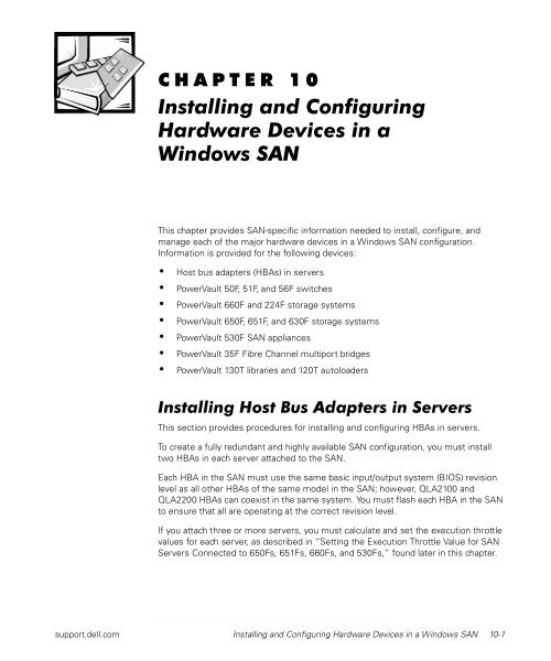
CHAPTER 10<br />
<strong>Install<strong>in</strong>g</strong> <strong>and</strong> <strong>Configur<strong>in</strong>g</strong><br />
<strong>Hardware</strong> <strong>Devices</strong> <strong>in</strong> a<br />
W<strong>in</strong>dows SAN<br />
This chapter provides SAN-specific <strong>in</strong>formation needed to <strong>in</strong>stall, configure, <strong>and</strong><br />
manage each of the major hardware devices <strong>in</strong> a W<strong>in</strong>dows SAN configuration.<br />
Information is provided for the follow<strong>in</strong>g devices:<br />
• Host bus adapters (HBAs) <strong>in</strong> servers<br />
• PowerVault 50F, 51F, <strong>and</strong> 56F switches<br />
• PowerVault 660F <strong>and</strong> 224F storage systems<br />
• PowerVault 650F, 651F, <strong>and</strong> 630F storage systems<br />
• PowerVault 530F SAN appliances<br />
• PowerVault 35F Fibre Channel multiport bridges<br />
• PowerVault 130T libraries <strong>and</strong> 120T autoloaders<br />
<strong>Install<strong>in</strong>g</strong> Host Bus Adapters <strong>in</strong> Servers<br />
This section provides procedures for <strong>in</strong>stall<strong>in</strong>g <strong>and</strong> configur<strong>in</strong>g HBAs <strong>in</strong> servers.<br />
To create a fully redundant <strong>and</strong> highly available SAN configuration, you must <strong>in</strong>stall<br />
two HBAs <strong>in</strong> each server attached to the SAN.<br />
Each HBA <strong>in</strong> the SAN must use the same basic <strong>in</strong>put/output system (BIOS) revision<br />
level as all other HBAs of the same model <strong>in</strong> the SAN; however, QLA2100 <strong>and</strong><br />
QLA2200HBAscancoexist<strong>in</strong>thesamesystem.YoumustflasheachHBA<strong>in</strong>theSAN<br />
to ensure that all are operat<strong>in</strong>g at the correct revision level.<br />
If you attach three or more servers, you must calculate <strong>and</strong> set the execution throttle<br />
values for each server, as described <strong>in</strong> “Sett<strong>in</strong>g the Execution Throttle Value for SAN<br />
Servers Connected to 650Fs, 651Fs, 660Fs, <strong>and</strong> 530Fs,” found later <strong>in</strong> this chapter.<br />
support.dell.com <strong>Install<strong>in</strong>g</strong> <strong>and</strong> <strong>Configur<strong>in</strong>g</strong> <strong>Hardware</strong> <strong>Devices</strong> <strong>in</strong> a W<strong>in</strong>dows SAN 10-1
10-2 <strong>Dell</strong> PowerVault SAN Adm<strong>in</strong>strator’s Guide<br />
NOTE: While you can attach a server to the SAN with only one HBA, <strong>Dell</strong> does not<br />
recommend this configuration. This configuration allows you to address logical unit<br />
numbers (LUNs) bound on only one storage controller, but the HBA, its attached<br />
cable, <strong>and</strong> the connected switch are a s<strong>in</strong>gle po<strong>in</strong>t-of-connection failure. In this configuration,<br />
none of the redundant or high-availability features are functional.<br />
To attach non-<strong>Dell</strong> servers to a <strong>Dell</strong> SAN, you must <strong>in</strong>stall a <strong>Dell</strong> PowerVault QLA2x00<br />
or QLA2x00F HBA <strong>in</strong> the non-<strong>Dell</strong> server, us<strong>in</strong>g an available Peripheral Component<br />
Interconnect (PCI) slot.<br />
Before You Beg<strong>in</strong><br />
NOTE: Current versions of software updates <strong>and</strong> the latest drivers are available from<br />
the <strong>Dell</strong> Web site at http://support.dell.com. W<strong>in</strong>dows NT <strong>and</strong> W<strong>in</strong>dows 2000 Service<br />
Packs are available from the Microsoft Web site at http://www.microsoft.com.<br />
To determ<strong>in</strong>e the correct revision levels of software <strong>and</strong> firmware for your SAN components,<br />
see the <strong>Dell</strong> PowerVault Systems Storage Area Network (SAN) Version 4.0<br />
Revision Compatibility Guide at http://support.dell.com.<br />
Before <strong>in</strong>stall<strong>in</strong>g the HBA hardware <strong>and</strong> software, perform the follow<strong>in</strong>g steps.<br />
NOTICE: Before you <strong>in</strong>stall W<strong>in</strong>dows NT, W<strong>in</strong>dows 2000, or NetWare on<br />
your server, ensure that the Fibre Channel HBAs are not plugged <strong>in</strong>to a<br />
PowerVault Fibre Channel switch. If the server is attached to the SAN, the<br />
W<strong>in</strong>dows NT or W<strong>in</strong>dows 2000 <strong>in</strong>stallation on your server may fail <strong>and</strong> data<br />
stored on the SAN may be corrupted.<br />
1. Install the Microsoft W<strong>in</strong>dows NT, W<strong>in</strong>dows 2000, Novell NetWare 4.2, or<br />
NetWare 5.1 operat<strong>in</strong>g system.<br />
2. Install <strong>and</strong> configure Transmission Control Protocol/Internet Protocol (TCP/IP) <strong>and</strong><br />
Simple Network Management Protocol (SNMP).<br />
3. Install the latest Service Pack(s) supported by <strong>Dell</strong> for the operat<strong>in</strong>g system.<br />
NOTICE: Failure to <strong>in</strong>stall the appropriate software update may result <strong>in</strong><br />
the <strong>in</strong>ability to manage the attached PowerVault storage systems. The high<br />
availability <strong>and</strong> redundancy features may not function <strong>in</strong> this situation.<br />
4. Install any appropriate Microsoft or Novell software updates.<br />
5. For W<strong>in</strong>dows NT <strong>and</strong> W<strong>in</strong>dows 2000, configure the server resolution to at least<br />
1024 x 768 pixels with a color depth of 65,536.<br />
<strong>Install<strong>in</strong>g</strong> the HBA<br />
Install the <strong>Dell</strong> PowerVault Fibre Channel HBA <strong>in</strong>to a 32- or 64-bit PCI slot that complies<br />
with the PCI 2.1 specification. The adapter should be recognized by the system<br />
board <strong>and</strong> operat<strong>in</strong>g system without additional configuration after the device driver is<br />
loaded.
NOTICE: If you are <strong>in</strong>stall<strong>in</strong>g the HBA <strong>in</strong> a Compaq server runn<strong>in</strong>g<br />
NetWare 5.1, you must disable survey.nlm before <strong>in</strong>stall<strong>in</strong>g the HBA. For<br />
more <strong>in</strong>formation, see the Compaq Web site at http://www.compaq.com.<br />
To <strong>in</strong>stall the HBA, perform the follow<strong>in</strong>g steps:<br />
1. Shut down the server.<br />
2. Remove the server cover.<br />
3. Remove the screw or clip, if applicable, <strong>and</strong> the slot cover.<br />
Reta<strong>in</strong> the screw to use when you <strong>in</strong>stall the adapter.<br />
If your server supports hot-swappable PCI, the slot cover may be attached with a<br />
clip <strong>in</strong>stead of a screw.<br />
4. Select an available PCI slot that supports bus-master<strong>in</strong>g.<br />
If the system board uses master <strong>and</strong> slave slots, select a master slot.<br />
If the system board uses shared slots, select a slot that is not shared.<br />
NOTICE: If you do not seat <strong>and</strong> secure the adapter properly, plugg<strong>in</strong>g or<br />
unplugg<strong>in</strong>g a cable may cause the adapter to shift <strong>in</strong> the slot, result<strong>in</strong>g <strong>in</strong> a<br />
poor connection or damage to the adapter <strong>and</strong> server.<br />
5. Insert the adapter <strong>in</strong>to the slot, carefully press<strong>in</strong>g down until it is firmly seated.<br />
6. Secure the adapter with the provided screw or clip.<br />
7. Replace the server cover.<br />
Your server <strong>and</strong> operat<strong>in</strong>g system should recognize the adapter <strong>and</strong> allocate needed<br />
resources without additional configuration.<br />
NOTE: If your non-<strong>Dell</strong> server does not recognize the QLogic HBA, see your server<br />
documentation for more <strong>in</strong>formation.<br />
<strong>Configur<strong>in</strong>g</strong> the HBA<br />
After <strong>in</strong>stall<strong>in</strong>g the HBA, you need to set the adapter’s nonvolatile r<strong>and</strong>om-access<br />
memory (NVRAM). You can f<strong>in</strong>d the ql2xutil.exe utility for sett<strong>in</strong>g the NVRAM on the<br />
bootable firmware <strong>and</strong> driver diskette you made from the <strong>Dell</strong> PowerVault Fibre Channel<br />
Utilities CD.<br />
NOTE: You can f<strong>in</strong>d the latest version of the driver <strong>and</strong> firmware file <strong>in</strong> the File Library<br />
at http://support.dell.com.<br />
You can use the ql2xutil.exe utility to flash both the NVRAM sett<strong>in</strong>gs <strong>and</strong> the BIOS.<br />
The utility uses data found <strong>in</strong> the .dat or .b<strong>in</strong> files, which are stored <strong>in</strong> the same directory<br />
as the utility. You need to create the diskette from the CD <strong>and</strong> boot the server<br />
us<strong>in</strong>g diskette 1 before runn<strong>in</strong>g the ql2xutil.exe utility.<br />
support.dell.com <strong>Install<strong>in</strong>g</strong> <strong>and</strong> <strong>Configur<strong>in</strong>g</strong> <strong>Hardware</strong> <strong>Devices</strong> <strong>in</strong> a W<strong>in</strong>dows SAN 10-3
10-4 <strong>Dell</strong> PowerVault SAN Adm<strong>in</strong>strator’s Guide<br />
Flash<strong>in</strong>g the NVRAM Sett<strong>in</strong>gs <strong>and</strong> BIOS on the HBA<br />
1. Create a bootable firmware <strong>and</strong> driver diskette from the <strong>Dell</strong> PowerVault Fibre<br />
Channel Utilities CD. See the QLogic documentation on the <strong>Dell</strong> PowerVault Fibre<br />
Channel Utilities CD for detailed <strong>in</strong>structions.<br />
a. Click QLogic QLA2100/QLA2200 PCI Fibre Channel Adapter.<br />
b. Click the appropriate self-extract<strong>in</strong>g diskette image.<br />
2. Insert firmware <strong>and</strong> driver diskette 1 <strong>in</strong>to the server’s diskettedrive.<br />
3. Turn on or reboot the server.<br />
4. At the MS-DOS ® or server console prompt, type cd flash <strong>and</strong> press .<br />
5. At the :\flash directory, type ql2xutil /L /F <strong>and</strong> press .<br />
The /L option <strong>in</strong> this comm<strong>and</strong> sets the NVRAM of every similar QLogic adapter<br />
<strong>in</strong>theservertothesett<strong>in</strong>gsfound<strong>in</strong>the.dat file. The /F option automatically<br />
flashes the BIOS of every similar QLogic adapter <strong>in</strong>stalled <strong>in</strong> the server, us<strong>in</strong>g the<br />
data found <strong>in</strong> the accompany<strong>in</strong>g .b<strong>in</strong> file. If you need to perform only one of<br />
these functions, use the appropriate option (/L or /F) <strong>in</strong> the comm<strong>and</strong>.<br />
NOTES: If you have both QLA2100 <strong>and</strong> QLA2200 adapters <strong>in</strong> your systems, you must<br />
create firmware <strong>and</strong> driver diskettes for each type of adapter.<br />
Verify the execution throttle value every time you flash the NVRAM se t<strong>in</strong>gs. Flash<strong>in</strong>g<br />
the NVRAM sets the value to 90, which is the highest value supported by <strong>Dell</strong>. However,<br />
the value should never exceed the default of 90. If the value is set too high,<br />
a tached servers may <strong>in</strong>dicate an I/O timeout spawned by the QLogic Fibre Channel<br />
device driver (ql2100 or ql2200) <strong>in</strong> the data section of the W<strong>in</strong>dows NT or W<strong>in</strong>dows<br />
2000 Event Viewer system log. Do not alter other NVRAM se t<strong>in</strong>gs from their default<br />
values unless directed to do so by <strong>Dell</strong> support personnel or by more recent <strong>Dell</strong><br />
documentation.<br />
If you are runn<strong>in</strong>g three or more servers, you must calculate <strong>and</strong> set the execution<br />
throttle value as described <strong>in</strong> “Se t<strong>in</strong>g the Execution Throttle Value for SAN Servers<br />
Connected to 650Fs, 651Fs, 660Fs, <strong>and</strong> 530Fs,” found later <strong>in</strong> this chapter.<br />
Sett<strong>in</strong>g the Execution Throttle Value for SAN Servers Connected to<br />
650Fs, 651Fs, 660Fs, <strong>and</strong> 530Fs<br />
In a SAN configuration with three or more servers, you must change the default execution<br />
throttle value <strong>in</strong> the NVRAM for each HBA.<br />
To calculate the execution throttle value, first determ<strong>in</strong>e whether all servers carry the<br />
same <strong>in</strong>put/output (I/O) load.<br />
If all servers carry the same I/O load, calculate the value by divid<strong>in</strong>g 240 by the number<br />
of servers <strong>in</strong> the SAN. Set each HBA <strong>in</strong> the SAN to the calculated value. For example,<br />
<strong>in</strong> a four-server configuration, divide 240 by 4 to arrive at 60. The execution throttle value<br />
for each HBA is, therefore, 60. Assign the value of 60 to all HBAs.
If some of the servers carry heavier I/O loads, first calculate the execution throttle<br />
value by divid<strong>in</strong>g 240 by the number of servers, <strong>and</strong> then adjust the values so that<br />
servers with higher I/O loads have higher execution throttle values <strong>and</strong> servers with<br />
lower I/O loads have lower execution throttle values. For example, <strong>in</strong> a four-server configuration,<br />
you might assign the value of 70 to the HBAs <strong>in</strong> the server with the highest<br />
I/O load, the value of 50 to the HBAs <strong>in</strong> the second server, <strong>and</strong> the value of 60 to the<br />
HBAs <strong>in</strong> the rema<strong>in</strong><strong>in</strong>g two servers.<br />
When calculat<strong>in</strong>g the server execution throttle value, note the follow<strong>in</strong>g:<br />
• <strong>Dell</strong> recommends that you set all HBAs <strong>in</strong> a server to the same execution throttle<br />
value.<br />
• The sum of execution throttle values should never exceed the maximum queue<br />
depth of 240.<br />
• When add<strong>in</strong>g the values, treat each server as hav<strong>in</strong>g a s<strong>in</strong>gle value. If the adapters<br />
<strong>in</strong> the first server are set to 70, the adapters <strong>in</strong> the second server are set to<br />
50, <strong>and</strong> the adapters <strong>in</strong> the third <strong>and</strong> fourth servers are set to 60, the sum is 240.<br />
• The execution throttle value for an HBA should never be set above 90.<br />
NOTICE: Sett<strong>in</strong>g the execution throttle value above 90 can cause data loss.<br />
To change the execution throttle value <strong>in</strong> the HBA NVRAM, perform the follow<strong>in</strong>g<br />
steps:<br />
1. Turn on or reboot the server.<br />
2. When the QLogic BIOS message appears dur<strong>in</strong>g the power-on self-test (POST),<br />
press .<br />
If the server has more than one controller <strong>in</strong>stalled, the Select Host Adapter<br />
screen appears, list<strong>in</strong>g each <strong>in</strong>stalled controller <strong>and</strong> the correspond<strong>in</strong>g address. If<br />
the server has only one controller <strong>in</strong>stalled, the Controller screen appears, list<strong>in</strong>g<br />
options for the selected controller.<br />
3. If the Select Host Adapter screen appears, press the up- or down-arrow key to<br />
highlight the controller you want <strong>and</strong> press .<br />
The Controller screen appears, list<strong>in</strong>g options for the selected controller.<br />
4. Press the up- or down-arrow key to highlight Configuration Sett<strong>in</strong>gs <strong>and</strong> press<br />
.<br />
The Configuration Sett<strong>in</strong>gs screen appears, list<strong>in</strong>g configuration sett<strong>in</strong>gs.<br />
5. Press the up- or down-arrow key to highlight Advanced Adapter Sett<strong>in</strong>gs <strong>and</strong><br />
press .<br />
The Advanced Adapter Sett<strong>in</strong>gs screen appears, display<strong>in</strong>g the current sett<strong>in</strong>gs<br />
for this adapter.<br />
6. For NetWare systems only, display the LUNs per target screen by press<strong>in</strong>g the<br />
up- or down-arrow key to highlight LUNs Per Target <strong>and</strong> then press<strong>in</strong>g .<br />
Forothersystems,gotostep8.<br />
support.dell.com <strong>Install<strong>in</strong>g</strong> <strong>and</strong> <strong>Configur<strong>in</strong>g</strong> <strong>Hardware</strong> <strong>Devices</strong> <strong>in</strong> a W<strong>in</strong>dows SAN 10-5
10-6 <strong>Dell</strong> PowerVault SAN Adm<strong>in</strong>strator’s Guide<br />
NOTE: You must set the range of the LUNs to the m<strong>in</strong>imum range that applies to<br />
the number of LUNs on the storage processor. Sett<strong>in</strong>g the LUNs per Target<br />
value to a higher value affects the time required for the server to boot. The maximum<br />
supported sett<strong>in</strong>g is 32. For a larger number of LUNs, <strong>Dell</strong> recommends<br />
hav<strong>in</strong>g at least 256 MB of r<strong>and</strong>om-access memory (RAM) <strong>in</strong> the server.<br />
7. Type the desired value, <strong>and</strong> press <br />
The Advanced Adapter Sett<strong>in</strong>gs screen is displayed, <strong>and</strong> the LUNs per Target<br />
value is set correctly.<br />
8. Press the up- or down-arrow key to highlight the execution throttle value <strong>and</strong><br />
press .<br />
The Enter Decimal Number screen appears.<br />
9. Type the desired value <strong>in</strong> the New column <strong>and</strong> press .<br />
The Advanced Adapter Sett<strong>in</strong>gs screen appears <strong>and</strong> the execution throttle<br />
value is now set correctly.<br />
If you need to change the value, repeat steps 8 <strong>and</strong> 9.<br />
10. Press the key twice, select Save Changes, <strong>and</strong> press .<br />
11. If you have more than one adapter, press the up- <strong>and</strong> down-arrow to highlight<br />
Select Host Adapter, <strong>and</strong> press <br />
12. Repeat this procedure for each adapter <strong>in</strong>stalled <strong>in</strong> each server <strong>in</strong> the SAN.<br />
13. After sett<strong>in</strong>g the execution throttle for all adapters <strong>in</strong> all servers <strong>in</strong> the SAN, press<br />
the up- or down-arrow key to highlight Exit Fast!UTIL, <strong>and</strong> press .<br />
14. Press the up- or down-arrow key to highlight Reboot System, <strong>and</strong> press<br />
.<br />
NOTE: Verify the execution throttle value every time you flash the NVRAM sett<strong>in</strong>gs.<br />
Flash<strong>in</strong>g the NVRAM sets the value to 90, which is the highest value supported by<br />
<strong>Dell</strong>. However, the value should never exceed the default of 90. If the value is set too<br />
high, attached servers may <strong>in</strong>dicate an I/O timeout spawned by the QLogic Fibre<br />
Channel device driver (ql2100 or ql2200) <strong>in</strong> the data section of the W<strong>in</strong>dows NT or<br />
W<strong>in</strong>dows 2000 Event Viewer system log. Do not alter other NVRAM se t<strong>in</strong>gs from<br />
their default values unless directed to do so by <strong>Dell</strong> support personnel or by more<br />
recent <strong>Dell</strong> documentation.<br />
Sett<strong>in</strong>g the Execution Throttle Value for Servers Attached Only to a<br />
PowerVault 530F<br />
The execution throttle value <strong>in</strong>structs the firmware how many I/Os per port can be<br />
active at any po<strong>in</strong>t <strong>in</strong> time. The execution throttle values for the servers that are<br />
attached only to a PowerVault 530F must be calculated differently from the other SAN<br />
components. For <strong>in</strong>structions on how to set the execution throttle for a PowerVault<br />
530F host server, see the <strong>Dell</strong> PowerVault 530F SAN Appliance Adm<strong>in</strong>istrator’s Guide.
If a server is attached to both a PowerVault 530F <strong>and</strong> a storage system through a<br />
switch, use the <strong>in</strong>structions <strong>in</strong> “Sett<strong>in</strong>g the Execution Throttle Value for SAN Servers<br />
Connected to 650Fs, 651Fs, 660Fs, <strong>and</strong> 530Fs,” which precedes this section.<br />
<strong>Install<strong>in</strong>g</strong> the QLogic HBA Drivers<br />
The QLogic HBA drivers allow the server to recognize any devices attached to the<br />
SAN.<br />
<strong>Install<strong>in</strong>g</strong> the HBA Drivers <strong>in</strong> W<strong>in</strong>dows NT<br />
The drivers for the Microsoft W<strong>in</strong>dows NT operat<strong>in</strong>g system are located on the <strong>Dell</strong><br />
PowerVault Fibre Channel Utilities CD <strong>and</strong><strong>in</strong>the:\nt4 directory of firmware<br />
<strong>and</strong> driver diskette 1 that you created from the CD. You can download the latest<br />
versions of these drivers from the <strong>Dell</strong> Web site at http://support.dell.com.<br />
NOTE: If an earlier version of the driver is <strong>in</strong>stalled, you must remove that version<br />
before <strong>in</strong>stall<strong>in</strong>g the new driver. You can remove the <strong>in</strong>stalled driver by click<strong>in</strong>g the<br />
SCSI Adapters icon <strong>in</strong> the Control Panel w<strong>in</strong>dow <strong>and</strong> follow<strong>in</strong>g the prompts.<br />
To <strong>in</strong>stall HBA drivers <strong>in</strong> W<strong>in</strong>dows NT, perform the follow<strong>in</strong>g steps:<br />
1. Turn on or reboot the server.<br />
Allow the server to boot completely.<br />
2. Insert the <strong>Dell</strong> PowerVault Fibre Channel Utilities CD <strong>in</strong>to the CD-ROM drive or<br />
<strong>in</strong>sertfirmware<strong>and</strong>driverdiskette1<strong>in</strong>totheserver’s diskette drive.<br />
3. Click Start—> Sett<strong>in</strong>gs, <strong>and</strong> click Control Panel.<br />
4. Double-click the SCSI Adapters icon.<br />
The SCSI Adapter w<strong>in</strong>dow appears.<br />
5. Click the Drivers tab.<br />
A list of all <strong>in</strong>stalled HBAs appears.<br />
6. Click Add.<br />
7. Click Have Disk.<br />
The cursor appears <strong>in</strong> the field designat<strong>in</strong>g the drive location.<br />
8. Typethepathtothedriversonthe<strong>Dell</strong> PowerVault Fibre Channel Utilities CD or<br />
to :\nt4 on firmware <strong>and</strong> driver diskette 1 <strong>and</strong> click OK.<br />
9. Select QLogic QLA2000/QLA2100 PCI-Fibre Channel Adapter or QLogic<br />
QLA2200 PCI-Fibre Channel Adapter from the list, <strong>and</strong> click OK.<br />
The HBA does not appear <strong>in</strong> the list of <strong>in</strong>stalled adapters until after you reboot.<br />
support.dell.com <strong>Install<strong>in</strong>g</strong> <strong>and</strong> <strong>Configur<strong>in</strong>g</strong> <strong>Hardware</strong> <strong>Devices</strong> <strong>in</strong> a W<strong>in</strong>dows SAN 10-7
10. Click OK.<br />
11. Reboot the server when prompted.<br />
10-8 <strong>Dell</strong> PowerVault SAN Adm<strong>in</strong>strator’s Guide<br />
Perform the preced<strong>in</strong>g steps on all servers attached to the SAN. You do not need to<br />
<strong>in</strong>stall the driver more than once, even on servers with multiple controllers <strong>in</strong>stalled.<br />
After you reboot the server, all HBAs <strong>in</strong>stalled <strong>in</strong> the server should be recognized <strong>and</strong><br />
listed when you double-click the SCSI Adapters icon <strong>in</strong> the Control Panel w<strong>in</strong>dow.<br />
Exp<strong>and</strong> the entry for each controller to view a list of attached devices.<br />
<strong>Install<strong>in</strong>g</strong> the HBA Drivers <strong>in</strong> W<strong>in</strong>dows 2000<br />
To <strong>in</strong>stall the HBA drivers <strong>in</strong> W<strong>in</strong>dows 2000, perform the follow<strong>in</strong>g steps:<br />
1. Turn on or reboot the server.<br />
2. Insert the <strong>Dell</strong> PowerVault Fibre Channel Utilities CD <strong>in</strong>to the CD-ROM drive.<br />
3. Right-click My Computer, clickProperties, <strong>and</strong> click the <strong>Hardware</strong> tab.<br />
4. Click Device Manager.<br />
5. In the Device Manager w<strong>in</strong>dow, double-click SCSI <strong>and</strong> RAID Controllers for<br />
QLA2100 HBAs or Unknown <strong>Devices</strong> for other HBAs.<br />
6. In the SCSI <strong>and</strong> RAID Controllers or Unknown <strong>Devices</strong> box, double-click the<br />
SCSI Controller icon for the HBA that is to be <strong>in</strong>stalled.<br />
7. In the HBA Adapter Properties w<strong>in</strong>dow, click the Driver tab, <strong>and</strong> then click<br />
Update Driver.<br />
8. In the Upgrade Device Driver Wizard w<strong>in</strong>dow, click Next, select Display a list<br />
of the known drivers for this device so that I can choose a specific driver,<br />
<strong>and</strong> then click Next aga<strong>in</strong>.<br />
9. Click Have Disk.<br />
10. When the Install from Disk w<strong>in</strong>dow appears <strong>and</strong> asks for the path to the driver<br />
location, browse to the path for the drivers on the <strong>Dell</strong> PowerVault Fibre Channel<br />
Utilities CD, open the correspond<strong>in</strong>g OEMSETUP.INF file, <strong>and</strong> click OK.<br />
11. Select Qlogic QLA2000/QLA2100 PCI Fibre Channel Adapter or QLA2200 PCI<br />
Fibre Channel Adapter from the list <strong>and</strong> click Next.<br />
12. Click Next to perform <strong>in</strong>stallation.<br />
13. Click F<strong>in</strong>ish.<br />
14. If the Digital Signature Not Found w<strong>in</strong>dow appears, click Yes to cont<strong>in</strong>ue the<br />
<strong>in</strong>stallation.<br />
15. In the System Properties w<strong>in</strong>dow, click OK.<br />
16. Repeat steps 3 through 15 for each HBA <strong>in</strong>stalled <strong>in</strong> the server.
17. When prompted, reboot the server.<br />
18. Perform steps 1 through 17 on all W<strong>in</strong>dows 2000 servers attached to the SAN.<br />
After you reboot the server, all HBAs <strong>in</strong>stalled <strong>in</strong> the server should be recognized <strong>and</strong><br />
listed <strong>in</strong> the Device Manager w<strong>in</strong>dow.<br />
<strong>Install<strong>in</strong>g</strong> the HBA Drivers <strong>in</strong> NetWare<br />
The drivers for the Novell NetWare operat<strong>in</strong>g system are located <strong>in</strong> the a:\netware<br />
directory of firmware <strong>and</strong> driver diskette 1 that you created from the <strong>Dell</strong> PowerVault<br />
Fibre Channel Utilities CD.<br />
To <strong>in</strong>stall HBA drivers <strong>in</strong> NetWare, perform the follow<strong>in</strong>g steps:<br />
1. Turn on or reboot the server.<br />
Allow the server to boot completely.<br />
NOTICE: If you have just <strong>in</strong>stalled you HBAs, the system will attempt to<br />
auto-detect the HBAs <strong>and</strong> <strong>in</strong>stall the older drivers dur<strong>in</strong>g the last part of<br />
the NetWare boot. If you allow the auto-detect to complete, you will need<br />
to un<strong>in</strong>stall the older drivers <strong>and</strong> <strong>in</strong>stall new drivers. To avoid this problem,<br />
press dur<strong>in</strong>g the boot process when you see the New Device Found<br />
w<strong>in</strong>dow to stop the driver <strong>in</strong>stallation. (You have about 10 seconds from the<br />
time the w<strong>in</strong>dow opens to press .)<br />
2. Insert firmware <strong>and</strong> driver diskette 1 <strong>in</strong>to the server’s diskette drive.<br />
3. Start the appropriate NetWare <strong>in</strong>stallation program.<br />
• For NetWare 4.2, type load <strong>in</strong>stall at the server console prompt.<br />
• For NetWare 5.1, type load nwconfig at the server console prompt.<br />
4. Select Driver Options.<br />
5. Select Configure disk <strong>and</strong> storage device drivers.<br />
6. Select Select an additional driver.<br />
7. Press to select Install an unlisted driver.<br />
8. If firmware <strong>and</strong> driver diskette 1 is <strong>in</strong> drive A, press .<br />
If firmware <strong>and</strong> driver diskette 1 is not <strong>in</strong> drive A, press to enter the correct<br />
path to firmware <strong>and</strong> driver diskette 1.<br />
9. Based on the HBAs <strong>in</strong>stalled <strong>in</strong> the server, select either QL2100.HAM or<br />
QL2200.HAM, <strong>and</strong> press .<br />
10. At the prompt Do you want to copy driver QL2100.HAM? (or<br />
QL2200.HAM?), select Yes.<br />
11. If you receive an <strong>in</strong>formational message, press to cont<strong>in</strong>ue.<br />
support.dell.com <strong>Install<strong>in</strong>g</strong> <strong>and</strong> <strong>Configur<strong>in</strong>g</strong> <strong>Hardware</strong> <strong>Devices</strong> <strong>in</strong> a W<strong>in</strong>dows SAN 10-9
10-10 <strong>Dell</strong> PowerVault SAN Adm<strong>in</strong>strator’s Guide<br />
12. At the Specify server boot path prompt, type the path to the server.exe<br />
file, or press to accept the default path of c:\nwserver.<br />
13. Select Select Modify driver parameters.<br />
14. Type the proper value for Slot Number, <strong>and</strong> press .<br />
NOTE: To obta<strong>in</strong> the slot number, perform the follow<strong>in</strong>g steps:<br />
a. Press until you get a console prompt.<br />
b. Type load ql2200 or load ql2100, <strong>and</strong> press to display the<br />
available slots. Make a note of the displayed slot numbers.<br />
c. In NetWare 4.2, press until the console prompt appears. In NetWare<br />
5.1, press to return to the console prompt.<br />
15. Leave Scan all Luns at the default value of Yes, <strong>and</strong> press to save the<br />
configuration.<br />
16. Select Save parameters <strong>and</strong> load driver.<br />
17. If you have a second adapter, select Yes at the prompt Do you want to<br />
select an additional Disk driver?, <strong>and</strong> then repeat steps 9 through 16<br />
for the second adapter.<br />
If you do not have a second adapter, select No at the prompt Do you want to<br />
select an additional Disk driver?.<br />
18. Select Return to previous menu twice.<br />
19. Select Exit to exit the <strong>in</strong>stallation program.<br />
The <strong>in</strong>stallation program makes all necessary additions <strong>and</strong> changes to the<br />
startup.ncf file <strong>and</strong> sets the values appropriately, so you do not need to adjust any<br />
driver sett<strong>in</strong>gs.<br />
<strong>Install<strong>in</strong>g</strong> <strong>and</strong> <strong>Configur<strong>in</strong>g</strong> PowerVault 50F,<br />
51F, <strong>and</strong> 56F Switches<br />
The <strong>Dell</strong> PowerVault 5xF Fibre Channel switch hardware consists of three basic<br />
pieces: the switch, the cables from the switch to servers or storage devices, <strong>and</strong> the<br />
gigabit <strong>in</strong>terface controllers (GBICs) <strong>in</strong>stalled <strong>in</strong> the switch. The switch should arrive<br />
from <strong>Dell</strong> with the GBICs properly <strong>in</strong>stalled.<br />
At least one of the <strong>in</strong>stalled GBICs is for a copper cable connection. Use this GBIC to<br />
connect the switch to one of the storage controllers <strong>in</strong> the <strong>Dell</strong> PowerVault 650F or<br />
651F disk processor enclosure (DPE) or to one of the <strong>Dell</strong> Fibre Disk RAID Controllers<br />
<strong>in</strong> the <strong>Dell</strong> PowerVault 660F storage system. The rema<strong>in</strong><strong>in</strong>g GBICs may use copper or<br />
optical cables.
On the PowerVault 50F switch, slots 6 <strong>and</strong> 7 are G ports (which can be either an E or<br />
F port) <strong>and</strong> slots 0 through 5 are Fabric Loop (FL) ports. Slots 6 <strong>and</strong> 7 do not function<br />
with a QLA2100/2100F host bus adapter (HBA). You can use slots 6 <strong>and</strong> 7 for cascad<strong>in</strong>g<br />
switches or for attach<strong>in</strong>g the QLA2200/2200F, PowerVault 35F bridge, or<br />
PowerVault 650F <strong>and</strong> 651F DPEs.<br />
On all other types of PowerVault switches, all ports are universal <strong>and</strong> can be <strong>in</strong>terconnected<br />
with another switch or any SAN component.<br />
<strong>Install<strong>in</strong>g</strong> the Switch <strong>Hardware</strong><br />
NOTE: The follow<strong>in</strong>g steps assume that the PowerVault 650F DPEs <strong>and</strong> PowerVault<br />
630F disk array enclosures (DAEs) have been <strong>in</strong>stalled as described <strong>in</strong> the <strong>Dell</strong> Power-<br />
Vault 650F <strong>and</strong> 630F Rack Installation Guides <strong>and</strong> that the PowerVault 660F <strong>and</strong> 224F<br />
storage systems have been <strong>in</strong>stalled as described <strong>in</strong> the <strong>Dell</strong> PowerVault 660F <strong>and</strong><br />
224F Rack Installation Guides. After the hardware <strong>in</strong>stallation of these components,<br />
the Fibre Channel storage system should be powered on, but not yet connected to a<br />
PowerVault Fibre Channel switch.<br />
1. Install the PowerVault Fibre Channel switch <strong>in</strong> its permanent physical location.<br />
This may be a rack or some other location.<br />
2. Use the DB-9–to–high-speed serial data connector (HSSDC) cable provided with<br />
the storage system to attach one of the storage controllers <strong>in</strong> the PowerVault<br />
650F or one of the <strong>Dell</strong> Fibre Disk RAID Controllers <strong>in</strong> the PowerVault 660F to<br />
one of the copper GBICs <strong>in</strong> the switch.<br />
3. Use the subscriber connector (SC)-to-SC or the HSSDC-to-HSSDC cables provided<br />
with the switch to connect the switch to one HBA <strong>in</strong> each server attached<br />
to the SAN, if you have not already done so.<br />
4. Connect the power cable, provided with the switch, to the switch <strong>and</strong> plug it <strong>in</strong>.<br />
<strong>Dell</strong> recommends that you use an un<strong>in</strong>terruptible power supply (UPS).<br />
5. Connect a twisted pair network cable to the Ethernet jack on the switch. This<br />
cable can be connected to a hub or a switch or, if a crossover cable is be<strong>in</strong>g used,<br />
directly to a network <strong>in</strong>terface controller (NIC). In the PowerVault 50F, the connection<br />
must run at 10 megabits per second (Mbps). After connect<strong>in</strong>g the cable, you<br />
must reboot the switch. Reboot<strong>in</strong>g the switch causes the Ethernet port on the<br />
switch to renegotiate network parameters.<br />
NOTE: For PowerVault 50F switches only, if you use an Ethernet hub or switch<br />
other than one runn<strong>in</strong>g at 10 Mbps, the port used must be configured to send<br />
<strong>and</strong> receive only at 10 Mbps. If a crossover cable is directly connected to a<br />
10/100-Mbps NIC, the NIC must be configured to send <strong>and</strong> receive at 10 Mbps.<br />
This completes the hardware <strong>in</strong>stallation for the switch.<br />
support.dell.com <strong>Install<strong>in</strong>g</strong> <strong>and</strong> <strong>Configur<strong>in</strong>g</strong> <strong>Hardware</strong> <strong>Devices</strong> <strong>in</strong> a W<strong>in</strong>dows SAN 10- 1
10-12 <strong>Dell</strong> PowerVault SAN Adm<strong>in</strong>strator’s Guide<br />
<strong>Configur<strong>in</strong>g</strong> the 50F <strong>and</strong> 51F Switch <strong>Hardware</strong><br />
When you <strong>in</strong>stall the Fibre Channel switch, you must set the Transmission Control<br />
Protocol/Internet Protocol (TCP/IP) parameters. If the TCP/IP addresses are not<br />
configured or are configured <strong>in</strong>correctly, IP communication to the switch does not<br />
function, prohibit<strong>in</strong>g the use of the switch’s Web-based management utilities, as well<br />
as any Telnet access.<br />
NOTE: You must attach the switch to a local area network (LAN) to flash the firmware<br />
on the switch because this procedure cannot be performed through the serial<br />
connection.<br />
To configure the IP address, subnet address, <strong>and</strong> gateway address for the switch, perform<br />
the follow<strong>in</strong>g steps:<br />
1. For a 50F <strong>and</strong> 51F switch, connect the DB-9–to–DB-9 cable, provided with the<br />
switch, to the serial port on the switch <strong>and</strong> to the serial port on a system with a<br />
term<strong>in</strong>al application <strong>in</strong>stalled.<br />
NOTE: It is not necessary to a tach the serial connection to a server <strong>in</strong> the SAN.<br />
This connection is used only briefly when configur<strong>in</strong>g the switch hardware. The<br />
length of the cable prohibits the use of any system that is not relatively close to<br />
the switch.<br />
2. On the system that is attached to the switch by the serial cable, open a term<strong>in</strong>al<br />
application.<br />
3. Configure the connection to use the correct COM port <strong>and</strong> the follow<strong>in</strong>g sett<strong>in</strong>gs:<br />
• Baud rate — 9600<br />
• Data Bits — 8<br />
• Parity — None<br />
• Stop Bits — 1<br />
• Flow Control — Xon/Xoff or None<br />
4. Power on the switch.<br />
The power-on self-test (POST) <strong>and</strong> boot process for the switch should appear <strong>in</strong><br />
the term<strong>in</strong>al w<strong>in</strong>dow.<br />
5. Log<strong>in</strong>totheswitchasadm<strong>in</strong> with the password password.<br />
NOTE: If the POST <strong>and</strong> boot <strong>in</strong>formation do not appear for an extended time, verify<br />
the connection to the switch, as well as the sett<strong>in</strong>gs for the term<strong>in</strong>al session.<br />
Also, you must use a straight serial cable like the one provided. A null modem<br />
cable will not work.<br />
6. Type ipAddrSet, <strong>and</strong> press .<br />
NOTE: The comm<strong>and</strong>s for the PowerVault 50F switch are case-sensitive.<br />
7. At the prompt, type the new Ethernet IP address, <strong>and</strong> press .<br />
8. At the prompt, type the new subnet mask, <strong>and</strong> press .
9. Press to accept the Fibre Channel IP address of (none). Do not change<br />
the address.<br />
NOTE: This is where an IP address would be configured if the switch were h<strong>and</strong>l<strong>in</strong>g<br />
IP communication over the Fibre Channel protocol. This is not currently<br />
implemented, but may be used at a later date.<br />
10. Press to accept the Fibre Channel subnet mask of (none). Donot<br />
change the address.<br />
11. At the f<strong>in</strong>al prompt, type the new gateway address, <strong>and</strong> press .<br />
The message Updat<strong>in</strong>g Flash appears. Then the prompts Set IP Address<br />
Now appears.<br />
12. Type y, <strong>and</strong> press to update the sett<strong>in</strong>gs immediately, without reboot<strong>in</strong>g<br />
the switch.<br />
13. If you <strong>in</strong>tend to monitor this switch with a <strong>Dell</strong> HP OpenView Network Node<br />
Manager Special Edition (NNM SE) console, perform the follow<strong>in</strong>g steps:<br />
a. Type agtcfgSet, <strong>and</strong> press .<br />
b. Press until the community name public appears, <strong>and</strong> press<br />
aga<strong>in</strong> to display the IP address.<br />
c. Type <strong>in</strong> the IP address of the HP OpenView management station, <strong>and</strong> press<br />
.<br />
d. Press at each prompt until the switch comm<strong>and</strong> prompt returns.<br />
14. To monitor, manage, or configure the switch through the Fabric Management<br />
tab <strong>in</strong> <strong>Dell</strong> PowerVault Switch Manager, you must <strong>in</strong>stall the Sun JavaSoft Java<br />
1.2.2 plug-<strong>in</strong> for W<strong>in</strong>dows, available on the <strong>Dell</strong> PowerVault Fibre Channel Utilities<br />
CD or <strong>Dell</strong> PowerVault Fibre Channel Update CD. Seethe<strong>Dell</strong> PowerVault Systems<br />
Storage Area Network (SAN) Version 4.0 Revision Compatibility Guide for<br />
the supported versions of Java.<br />
15. After <strong>in</strong>stall<strong>in</strong>g the applet, open your Internet browser, enter the switch name or<br />
switch IP address, <strong>and</strong> press . For more <strong>in</strong>formation, see Chapter 15,<br />
“Manag<strong>in</strong>g Fibre Channel Fabric Switch Zones,” or the <strong>Dell</strong> PowerVault Switch<br />
Manager User’s Guide.<br />
16. If you use any browser other than a Java-enabled Web browser or any other version<br />
of Java, some features may not be displayed. In this case, you must turn off<br />
the browser cache feature for proper operation.<br />
17. Disconnect the serial cable from the switch.<br />
18. Repeat this procedure for all rema<strong>in</strong><strong>in</strong>g switches.<br />
The switch is now configured to allow management through the Ethernet <strong>in</strong>terface. It<br />
can be accessed by open<strong>in</strong>g a Telnet session with the switch’s IP address or by po<strong>in</strong>t<strong>in</strong>g<br />
a Web browser to the switch’s IP address.<br />
support.dell.com <strong>Install<strong>in</strong>g</strong> <strong>and</strong> <strong>Configur<strong>in</strong>g</strong> <strong>Hardware</strong> <strong>Devices</strong> <strong>in</strong> a W<strong>in</strong>dows SAN 10-13
10-14 <strong>Dell</strong> PowerVault SAN Adm<strong>in</strong>strator’s Guide<br />
<strong>Configur<strong>in</strong>g</strong> the 56F Switch <strong>Hardware</strong><br />
You must configure the IP address, subnet address, <strong>and</strong> gateway address. You can<br />
configure the <strong>Dell</strong> PowerVault 56F switch us<strong>in</strong>g the <strong>in</strong>tegrated LCD control panel <strong>and</strong><br />
associated buttons.<br />
You can configure the switch by us<strong>in</strong>g the Configuration Menu. Press<strong>in</strong>g the rightarrow<br />
<strong>and</strong> left-arrow buttons while <strong>in</strong> the Configuration Menu selects the option to<br />
choose comm<strong>and</strong>s. The follow<strong>in</strong>g sections conta<strong>in</strong> the Configuration Menu options<br />
<strong>and</strong> give detailed <strong>in</strong>formation about each configuration comm<strong>and</strong>.<br />
NOTES: After mak<strong>in</strong>g any changes us<strong>in</strong>g the front panel, you must reboot the switch<br />
for the changes to take effect.<br />
In addition to mov<strong>in</strong>g the cursor, the right-arrow button can function as an <br />
key, <strong>and</strong> the left-arrow button can function as a key.<br />
Ethernet IP Address<br />
Press<strong>in</strong>g the right-arrow button with Ethernet IP address selected displays the<br />
switch’s Ethernet IP address.<br />
The switch’s default IP address is a temporary address derived from the switch’s<br />
World-Wide Name (WWN). Enter a valid IP address by perform<strong>in</strong>g the follow<strong>in</strong>g steps:<br />
1. Use the up- <strong>and</strong> down-arrow buttons on the front of the LED display on the<br />
switch to <strong>in</strong>crease or decrease the displayed value. The underl<strong>in</strong>ed cursor <strong>in</strong>dicates<br />
the numbers to modify.<br />
When enter<strong>in</strong>g a number, the up- <strong>and</strong> down-arrow buttons start <strong>in</strong> the slow mode<br />
<strong>and</strong> move to the fast mode if the button is held down. The numbers go to a maximum<br />
of 255 <strong>and</strong> then return to zero; for a large number, it may be faster to use<br />
the down-arrow button.<br />
2. After enter<strong>in</strong>g a number, press the right-arrow button to move the cursor to the<br />
next field.<br />
3. After sett<strong>in</strong>g the IP address, press the right-arrow button to store the value.<br />
Ethernet Subnetmask<br />
Press<strong>in</strong>g the right-arrow button while Ethernet Subnetworkmask is selected displays<br />
the Ethernet subnet mask address.<br />
The default subnet mask value is none. Refer to the network adm<strong>in</strong>istrator for the<br />
appropriate subnet mask.<br />
Enter the switch’s subnet address by us<strong>in</strong>g the up- <strong>and</strong> down-arrow buttons to<br />
<strong>in</strong>crease or decrease the displayed value. The underl<strong>in</strong>ed cursor <strong>in</strong>dicates the<br />
numbers to modify.<br />
Gateway Address<br />
Press<strong>in</strong>g the right-arrow button while Gateway address is selected displays the Fibre<br />
Channel switch’s gateway address.
The default gateway address is 0.0.0.0. You must enter a valid gateway address, if<br />
required, by perform<strong>in</strong>g the follow<strong>in</strong>g steps:<br />
1. Use the up- <strong>and</strong> down-arrow buttons to <strong>in</strong>crease or decrease the displayed value.<br />
The underl<strong>in</strong>ed cursor <strong>in</strong>dicates the numbers to modify.<br />
2. After enter<strong>in</strong>g a number, press the right-arrow button to move the cursor to the<br />
next field.<br />
3. After sett<strong>in</strong>g the Fibre Channel switch’s IP address, press the right-arrow button<br />
to store the value.<br />
Additional Information<br />
For additional <strong>in</strong>formation about your PowerVault Fibre Channel switch, see the documentation<br />
that came with your product. You can also access the documentation from<br />
the <strong>Dell</strong> support Web site at http://support.dell.com.<br />
<strong>Install<strong>in</strong>g</strong> <strong>and</strong> <strong>Configur<strong>in</strong>g</strong> PowerVault<br />
660F <strong>and</strong> 224F Storage Systems<br />
For specific <strong>in</strong>formation about <strong>in</strong>stall<strong>in</strong>g <strong>and</strong> configur<strong>in</strong>g the <strong>Dell</strong> PowerVault 660F <strong>and</strong><br />
224F rack-mountable storage systems, refer to the <strong>Dell</strong> PowerVault 660 <strong>and</strong> 224F<br />
User’s Guide, the<strong>Dell</strong> PowerVault 660F <strong>and</strong> 224F Installation <strong>and</strong> Troubleshoot<strong>in</strong>g<br />
Guide, the<strong>Dell</strong> OpenManage Array Manager User’s Guide,the<strong>Dell</strong> OpenManage<br />
Storage Consolidation User’s Guide, <strong>and</strong>the<strong>Dell</strong> PowerVault Systems Storage Area<br />
Network (SAN) Version 4.0 Revision Compatibility Guide.<br />
Perform the follow<strong>in</strong>g steps to <strong>in</strong>stall <strong>and</strong> configure the storage system:<br />
1. Assess your site, <strong>in</strong>clud<strong>in</strong>g requirements for rack(s), power, airflow, <strong>and</strong> cool<strong>in</strong>g.<br />
For specific requirements for each SAN component, see Appendix B, “Site Plann<strong>in</strong>g<br />
Information.”<br />
2. Determ<strong>in</strong>e your cabl<strong>in</strong>g requirements, verify availability <strong>and</strong> <strong>in</strong>stallation of cabl<strong>in</strong>g,<br />
<strong>and</strong> verify cable lengths <strong>and</strong> connector types. For specific requirements for each<br />
SAN component, see Appendix A, “Cable Types.”<br />
3. Install storage systems <strong>in</strong>to racks, connect<strong>in</strong>g any PowerVault 224F systems to<br />
PowerVault 660F systems, as required. For detailed <strong>in</strong>structions, see the Rack<br />
Installation Guide that came with your SAN components.<br />
4. Perform any necessary updates to exist<strong>in</strong>g SAN components that will be<br />
attached to or access<strong>in</strong>g the storage enclosures. For <strong>in</strong>structions, see Chapter<br />
9,”Upgrad<strong>in</strong>g Your <strong>Dell</strong> PowerVault Fibre Channel Software <strong>and</strong> Firmware,” as<br />
well as the <strong>Dell</strong> PowerVault Systems Storage Area Network (SAN) Version 4.0<br />
Revision Compatibility Guide for required revision levels.<br />
5. If not previously <strong>in</strong>stalled, <strong>in</strong>stall all storage software components as required to<br />
configure <strong>and</strong> manage the newly <strong>in</strong>stalled storage systems. For detailed <strong>in</strong>structions<br />
regard<strong>in</strong>g the <strong>in</strong>stallation of the software components needed to configure<br />
support.dell.com <strong>Install<strong>in</strong>g</strong> <strong>and</strong> <strong>Configur<strong>in</strong>g</strong> <strong>Hardware</strong> <strong>Devices</strong> <strong>in</strong> a W<strong>in</strong>dows SAN 10-15
10-16 <strong>Dell</strong> PowerVault SAN Adm<strong>in</strong>strator’s Guide<br />
<strong>and</strong> manage your storage systems, see Chapter 11, “<strong>Install<strong>in</strong>g</strong>, <strong>Configur<strong>in</strong>g</strong>, <strong>and</strong><br />
Remov<strong>in</strong>g Microsoft W<strong>in</strong>dows SAN Software Components.”<br />
6. Turn on the power, connect the storage systems to the SAN, <strong>and</strong>, if necessary,<br />
create zone configurations to manage access to the newly <strong>in</strong>stalled storage. For<br />
more <strong>in</strong>formation, see the appropriate sections <strong>in</strong> this chapter. For <strong>in</strong>formation<br />
about zon<strong>in</strong>g configurations, see Chapter 15, “Manag<strong>in</strong>g Fibre Channel Fabric<br />
Switch Zones.”<br />
7. Access the storage systems us<strong>in</strong>g <strong>Dell</strong> Open Manage Array Manager. Configure<br />
virtual disks (LUNs) as needed for the SAN configuration. For <strong>in</strong>formation about<br />
this program, see Chapter 11, “<strong>Install<strong>in</strong>g</strong>, <strong>Configur<strong>in</strong>g</strong>, <strong>and</strong> Remov<strong>in</strong>g Microsoft<br />
W<strong>in</strong>dows SAN Software Components.”<br />
8. Assign the newly created virtual disks (LUNs) to the desired host servers us<strong>in</strong>g<br />
<strong>Dell</strong> OpenManage Storage Consolidation software. For detailed <strong>in</strong>structions, see<br />
the <strong>Dell</strong> OpenManage Storage Consolidation User’s Guide.<br />
9. Configure <strong>and</strong> format the hard-disk drives <strong>and</strong> create any volumes needed for<br />
access by the SAN host server operat<strong>in</strong>g systems. For <strong>in</strong>formation, see your<br />
operat<strong>in</strong>g system documentation or the <strong>Dell</strong> OpenManage Array Manager User’s<br />
Guide.<br />
Additional Information<br />
For additional <strong>in</strong>formation about your PowerVault 660F <strong>and</strong> 224F Storage Systems,<br />
see the documentation that came with your product or the various readme files on<br />
the <strong>Dell</strong> PowerVault Fibre Channel Utilities CD Version 4.0 <strong>and</strong> the <strong>Dell</strong> PowerVault<br />
Fibre Channel Update CD Version 4.0. You can also access the documentation from<br />
the <strong>Dell</strong> support Web site at http://support.dell.com.<br />
For additional <strong>in</strong>formation on check<strong>in</strong>g <strong>and</strong> updat<strong>in</strong>g your firmware levels, see the <strong>Dell</strong><br />
PowerVault Systems Storage Area Network (SAN) Version 4.0 Revision Compatibility<br />
Guide.<br />
<strong>Install<strong>in</strong>g</strong> <strong>and</strong> <strong>Configur<strong>in</strong>g</strong> the PowerVault<br />
650F, 651F, <strong>and</strong> 630F Storage Systems<br />
For specific <strong>in</strong>formation about <strong>in</strong>stall<strong>in</strong>g <strong>and</strong> configur<strong>in</strong>g <strong>Dell</strong> PowerVault 650F <strong>and</strong><br />
651F rack-mountable disk processor enclosures (DPEs) <strong>and</strong> the <strong>Dell</strong> PowerVault 630F<br />
disk array enclosures (DAEs), refer to the system’s Installation <strong>and</strong> Service Guide, the<br />
<strong>Dell</strong> OpenManage Data Supervisor, Event Monitor, <strong>and</strong> Integrator Installation <strong>and</strong><br />
Operation document, <strong>and</strong> the <strong>Dell</strong> PowerVault Systems Storage Area Network (SAN)<br />
Version 4.0 Revision Compatibility Guide.<br />
Perform the follow<strong>in</strong>g steps to <strong>in</strong>stall <strong>and</strong> configure the storage system:<br />
1. Assess your site, <strong>in</strong>clud<strong>in</strong>g requirements for racks, power, airflow, <strong>and</strong> cool<strong>in</strong>g.<br />
For specific requirements for each SAN component, see Appendix B, “Site Plann<strong>in</strong>g<br />
Information.”
2. Determ<strong>in</strong>e your cabl<strong>in</strong>g requirements, verify availability <strong>and</strong> <strong>in</strong>stallation of cabl<strong>in</strong>g,<br />
<strong>and</strong> verify cable lengths <strong>and</strong> connector types. For specific requirements for each<br />
SAN component, see Appendix A, “Cable Types.”<br />
3. Install the storage enclosures <strong>in</strong>to racks <strong>and</strong> connect PowerVault 630F systems<br />
to PowerVault 650F systems, as required. For detailed <strong>in</strong>structions, see the Rack<br />
Installation Guide that came with your SAN components.<br />
4. Perform any necessary updates to exist<strong>in</strong>g SAN components that will be<br />
attached to or access<strong>in</strong>g the storage enclosures. For <strong>in</strong>structions, see Chapter<br />
9,”Upgrad<strong>in</strong>g Your <strong>Dell</strong> PowerVault Fibre Channel Software <strong>and</strong> Firmware,” as<br />
well as the <strong>Dell</strong> PowerVault Systems Storage Area Network (SAN) Version 4.0<br />
Revision Compatibility Guide for required revision levels.<br />
5. If not previously <strong>in</strong>stalled, <strong>in</strong>stall all storage software components as required to<br />
configure <strong>and</strong> manage the newly <strong>in</strong>stalled storage systems. For detailed <strong>in</strong>structions<br />
regard<strong>in</strong>g the <strong>in</strong>stallation of the software components needed to configure<br />
<strong>and</strong> manage your storage systems, see Chapter 11, “<strong>Install<strong>in</strong>g</strong>, <strong>Configur<strong>in</strong>g</strong>, <strong>and</strong><br />
Remov<strong>in</strong>g Microsoft W<strong>in</strong>dows SAN Software Components,” <strong>and</strong> Chapter 12,<br />
“<strong>Install<strong>in</strong>g</strong>, <strong>Configur<strong>in</strong>g</strong>, <strong>and</strong> Un<strong>in</strong>stall<strong>in</strong>g Components <strong>in</strong> a Novell NetWare SAN.”<br />
6. Turn on the power, connect the storage systems to the SAN, <strong>and</strong>, if necessary,<br />
create zone configurations to manage access to the newly <strong>in</strong>stalled storage. For<br />
more <strong>in</strong>formation, see the appropriate sections <strong>in</strong> this chapter. For <strong>in</strong>formation<br />
about zon<strong>in</strong>g configurations, see Chapter 15, “Manag<strong>in</strong>g Fibre Channel Fabric<br />
Switch Zones.”<br />
7. Access the storage systems us<strong>in</strong>g <strong>Dell</strong> OpenManage Data Supervisor. Configure<br />
LUNs as needed for the SAN configuration. For <strong>in</strong>formation about this program,<br />
see Chapter 11, “<strong>Install<strong>in</strong>g</strong>, <strong>Configur<strong>in</strong>g</strong>, <strong>and</strong> Remov<strong>in</strong>g Microsoft W<strong>in</strong>dows<br />
SAN Software Components.”<br />
8. Assign the newly created LUNs to the desired host servers us<strong>in</strong>g <strong>Dell</strong><br />
OpenManage Storage Consolidation software. For detailed <strong>in</strong>structions, see the<br />
<strong>Dell</strong> OpenManage Storage Consolidation User’s Guide.<br />
9. Configure <strong>and</strong> format the hard-disk drives <strong>and</strong> create any volumes needed for<br />
access by the SAN host server operat<strong>in</strong>g systems. For <strong>in</strong>formation, see your<br />
operat<strong>in</strong>g system documentation or the <strong>Dell</strong> OpenManage Array Manager User’s<br />
Guide.<br />
Additional Information<br />
For additional <strong>in</strong>formation about your PowerVault 650F or 651F DPE, see the documentation<br />
that came with your product or the various readme files on the <strong>Dell</strong><br />
PowerVault Fibre Channel Utilities CD Version 4.0 or the <strong>Dell</strong> PowerVault Fibre Channel<br />
Update CD Version 4.0. You can also access the documentation from the <strong>Dell</strong><br />
support Web site at http://support.dell.com.<br />
For additional <strong>in</strong>formation on check<strong>in</strong>g <strong>and</strong> updat<strong>in</strong>g your firmware levels, see the <strong>Dell</strong><br />
OpenManage Data Supervisor, Event Monitor, <strong>and</strong> Integrator Installation <strong>and</strong> Operation<br />
document <strong>and</strong> the <strong>Dell</strong> PowerVault Systems Storage Area Network (SAN) Version<br />
4.0 Revision Compatibility Guide.<br />
support.dell.com <strong>Install<strong>in</strong>g</strong> <strong>and</strong> <strong>Configur<strong>in</strong>g</strong> <strong>Hardware</strong> <strong>Devices</strong> <strong>in</strong> a W<strong>in</strong>dows SAN 10-17
10-18 <strong>Dell</strong> PowerVault SAN Adm<strong>in</strong>strator’s Guide<br />
<strong>Install<strong>in</strong>g</strong> <strong>and</strong> <strong>Configur<strong>in</strong>g</strong> the PowerVault<br />
530F SAN Appliance<br />
Due to the number of different storage area network (SAN) configurations that can be<br />
set up us<strong>in</strong>g the PowerVault 530F, refer to the follow<strong>in</strong>g documents for detailed setup<br />
<strong>and</strong> configuration procedures:<br />
• <strong>Dell</strong> PowerVault 530F SAN Appliance Adm<strong>in</strong>istrator’s Guide<br />
• <strong>Dell</strong> OpenManage Data Supervisor, Event Monitor, <strong>and</strong> Integrator Installation <strong>and</strong><br />
Operation document<br />
• <strong>Dell</strong> PowerVault Systems Storage Area Network (SAN) Version 4.0 Revision<br />
Compatibility Guide.<br />
NOTE: For scalability, PowerVault 56F switches are recommended <strong>and</strong> 51F switches<br />
are supported between the servers <strong>and</strong> the 530F. PowerVault 51F <strong>and</strong> 56F switches<br />
are supported between the 530F <strong>and</strong> the storage system. (PowerVault 50F switches<br />
are not supported <strong>in</strong> PowerVault 530F SAN configurations.)<br />
These steps are an overview of the PowerVault 530F setup <strong>and</strong> configuration. Refer to<br />
the <strong>Dell</strong> PowerVault 530F System Adm<strong>in</strong>istrator’s Guidewhile perform<strong>in</strong>g each of<br />
these steps.<br />
1. Assess site, cabl<strong>in</strong>g, <strong>and</strong> address<strong>in</strong>g requirements.<br />
2. Perform any necessary upgrades to software <strong>and</strong> firmware on all SAN<br />
components.<br />
3. Install the PowerVault 530F SAN appliance <strong>in</strong> a rack.<br />
4. Turn on the power to the PowerVault 530F <strong>and</strong> allow it to boot. The appliance<br />
emits short beeps at the completion of a successful boot.<br />
5. To perform the <strong>in</strong>itial configuration, select a W<strong>in</strong>dows NT or W<strong>in</strong>dows 2000<br />
server that can be connected by a crossover cable to the appliance. This server<br />
must conta<strong>in</strong> an Ethernet port to allow crossover cable connection to the<br />
appliance.<br />
6. Copy the Virtual Network Comput<strong>in</strong>g (VNC) client software from the <strong>Dell</strong> Power-<br />
Vault Fibre Channel Utilities CD Version 4.0 onto the server used for the <strong>in</strong>itial<br />
configuration.<br />
7. Set the Internet Protocol (IP) address <strong>and</strong> subnet mask <strong>in</strong> this server for communication<br />
with the PowerVault 530F.<br />
8. Use the crossover cable that came with your PowerVault 530F to attach it to the<br />
server used for the <strong>in</strong>itial configuration.<br />
9. Use the VNC client software to access the PowerVault 530F, <strong>and</strong> then perform<br />
the <strong>in</strong>itial configuration of the PowerVault 530F’s network sett<strong>in</strong>gs.<br />
10. Connect the appliance to the local area network (LAN) <strong>and</strong> use a browser to<br />
launch the SAN Appliance Software on the PowerVault 530F that is to be<br />
configured.
11. Set the appliance's mode of operation.<br />
12. Connect the PowerVault storage devices <strong>and</strong> host servers to the appliance.<br />
13. If applicable, set the failover paths for the 660F on the 530F.<br />
14. For 660Fs, use <strong>Dell</strong> OpenManage Array Manager to configure the storage systems<br />
attached to the 530F.<br />
15. For 650Fs, use the Data Agent menu option <strong>in</strong> the PowerVault 530F Menu Application<br />
to scan for storage devices.<br />
16. For 650Fs, use <strong>Dell</strong> OpenManage Data Supervisor or Data Adm<strong>in</strong>istrator runn<strong>in</strong>g<br />
on a LAN-attached management station to configure the PowerVault storage<br />
devices, <strong>in</strong>clud<strong>in</strong>g b<strong>in</strong>d<strong>in</strong>g the logical unit numbers (LUNs).<br />
17. Configure the host servers.<br />
a. Install or update the host bus adapter (HBA) software drivers, as required.<br />
b. Install the QLogic Fibre Channel Configuration Utility as described <strong>in</strong> the <strong>Dell</strong><br />
PowerVault 530F System Adm<strong>in</strong>istrator’s Guide.<br />
c. Install the QLogic QLDirect driver on each host server that is attached to the<br />
PowerVault 530F.<br />
d. Set the failover paths, if applicable, on the host servers.<br />
18. If the PowerVault 530F is part of a mirrored or redundant configuration, make<br />
the appropriate Fibre Channel Protocol (FCP) <strong>and</strong> IP connections between the<br />
appliances.<br />
19. Cont<strong>in</strong>ue the configuration of the PowerVault 530F us<strong>in</strong>g the SAN Appliance<br />
Software, <strong>in</strong>clud<strong>in</strong>g mapp<strong>in</strong>g LUNs to the host servers, <strong>and</strong> then perform the<br />
rema<strong>in</strong><strong>in</strong>g appliance configuration tasks, such as configur<strong>in</strong>g LUN mirror<strong>in</strong>g, LUN<br />
partition<strong>in</strong>g, or Snapshot Copy (po<strong>in</strong>t-<strong>in</strong>-time copy).<br />
20. Install selected SAN tape-backup software onto host servers, if used. For <strong>in</strong>structions,<br />
see the tape-backup software documentation.<br />
Additional Information<br />
For additional <strong>in</strong>formation about your SAN, SAN components, or <strong>Dell</strong> PowerVault 530F<br />
SAN appliance, see the documentation that came with your product or the various<br />
readme files <strong>and</strong> documentation on the <strong>Dell</strong> PowerVault Fibre Channel Utilities CD<br />
Version 4.0 or the <strong>Dell</strong> PowerVault Fibre Channel Update CD Version 4.0. Youcanalso<br />
access the documentation at the <strong>Dell</strong> support Web site at http://support.dell.com.<br />
<strong>Install<strong>in</strong>g</strong> <strong>and</strong> <strong>Configur<strong>in</strong>g</strong> the PowerVault<br />
35F Fibre Channel Multiport Bridge<br />
This section describes how to <strong>in</strong>stall <strong>and</strong> configure the <strong>Dell</strong> PowerVault 35F Fibre<br />
Channel multiport bridge.<br />
support.dell.com <strong>Install<strong>in</strong>g</strong> <strong>and</strong> <strong>Configur<strong>in</strong>g</strong> <strong>Hardware</strong> <strong>Devices</strong> <strong>in</strong> a W<strong>in</strong>dows SAN 10-19
10-20 <strong>Dell</strong> PowerVault SAN Adm<strong>in</strong>strator’s Guide<br />
<strong>Install<strong>in</strong>g</strong> the <strong>Dell</strong> PowerVault 35F Bridge<br />
To connect the PowerVault 35F Fibre Channel multiport bridge to the storage area network<br />
(SAN), verify that an optical gigabit <strong>in</strong>terface controller (GBIC) is available <strong>in</strong> one<br />
of the <strong>Dell</strong> PowerVault Fibre Channel switches currently <strong>in</strong>stalled <strong>in</strong> the SAN. Plug one<br />
end of a fiber-optic cable <strong>in</strong>to the optical GBIC of the Fibre Channel switch <strong>and</strong> connect<br />
the other end of the cable to the optical GBIC on the bridge.<br />
<strong>Configur<strong>in</strong>g</strong> the <strong>Dell</strong> PowerVault 35F Bridge<br />
<strong>Dell</strong> recommends that you configure the remote management capabilities of the <strong>Dell</strong><br />
PowerVault 35F bridge. For more <strong>in</strong>formation, see “<strong>Install<strong>in</strong>g</strong> <strong>and</strong> <strong>Configur<strong>in</strong>g</strong> the<br />
PowerVault 130T Library <strong>and</strong> 120T Autoloader” <strong>in</strong> this chapter or the <strong>Dell</strong> PowerVault<br />
35F Fibre Channel Multiport Bridge User’s Guide. Connect<strong>in</strong>g the bridge to the<br />
PowerVault Fibre Channel switch <strong>and</strong> PowerVault high-voltage differential (HVD) small<br />
computer systems <strong>in</strong>terface (SCSI) library or autoloader prepares it for operation.<br />
NOTES: Install <strong>and</strong> configure the <strong>Dell</strong> PowerVault HVD SCSI library or autoloader<br />
before you power on the bridge so that you do not have to cycle power on the bridge<br />
after you <strong>in</strong>stall the library or autoloader.<br />
Refer to the PowerVault 35F User’s Guide for <strong>in</strong>formation about configur<strong>in</strong>g the bridge<br />
to support remote management.<br />
Additional Information<br />
For additional <strong>in</strong>formation about your PowerVault 35F Fibre Channel multiport bridge,<br />
see the documentation that came with your product. You can also access the documentation<br />
from the <strong>Dell</strong> support Web site at http://support.dell.com.<br />
<strong>Install<strong>in</strong>g</strong> <strong>and</strong> <strong>Configur<strong>in</strong>g</strong> the PowerVault<br />
130T Library <strong>and</strong> 120T Autoloader<br />
This section describes how to <strong>in</strong>stall <strong>and</strong> configure the <strong>Dell</strong> PowerVault 130T digital<br />
l<strong>in</strong>ear tape (DLT) library <strong>and</strong> the <strong>Dell</strong> PowerVault 120T DLT autoloader.<br />
<strong>Install<strong>in</strong>g</strong> the <strong>Dell</strong> PowerVault 130T DLT Library<br />
To connect the PowerVault 130T to the PowerVault 35F bridge, you will need the<br />
appropriate small computer system <strong>in</strong>terface (SCSI) cables <strong>and</strong> term<strong>in</strong>ators. Two SCSI<br />
connectors are located near the upper-right corner on the back of the PowerVault<br />
130T, <strong>and</strong> two SCSI connectors are located on the back of each DLT drive <strong>in</strong>stalled <strong>in</strong><br />
the PowerVault 130T.<br />
To connect the devices, perform the follow<strong>in</strong>g steps:<br />
1. Connect the first SCSI cable to one of the bottom SCSI connectors on the back of<br />
the PowerVault 35F.
2. Connect the other end of the SCSI cable to the upper-right SCSI connector on the<br />
PowerVault 130T.<br />
3. Connect a right-angle SCSI cable to the SCSI connector to the left of the previous<br />
connector.<br />
4. Connect the other end of the right-angle SCSI cable to the first DLT drive, located<br />
near the bottom-left corner of the PowerVault 130T (see Figure 10-1).<br />
5. If there is more than one DLT drive <strong>in</strong> the PowerVault 130T, connect another SCSI<br />
cable from the left SCSI connector on the first DLT drive to the right SCSI connectorontheDLTdriveaboveit.<br />
6. Repeat step 5 for each additional DLT drive <strong>in</strong> the PowerVault 130T. To maximize<br />
performance, connect no more than two DLT drives to each PowerVault 35F SCSI<br />
bus (see Figure 10-2).<br />
7. After all SCSI cabl<strong>in</strong>g is <strong>in</strong>stalled, each end of the SCSI bus needs to be<br />
term<strong>in</strong>ated.<br />
a. On the PowerVault 35F, connect one SCSI term<strong>in</strong>ator to the top SCSI connector<br />
of the bus connected to the PowerVault 130T.<br />
b. On the PowerVault 130T, connect the second term<strong>in</strong>ator to the left SCSI<br />
connector on the last DLT drive <strong>in</strong> the cha<strong>in</strong>.<br />
Figure 10-1. <strong>Install<strong>in</strong>g</strong> a 130T DLT Library<br />
support.dell.com <strong>Install<strong>in</strong>g</strong> <strong>and</strong> <strong>Configur<strong>in</strong>g</strong> <strong>Hardware</strong> <strong>Devices</strong> <strong>in</strong> a W<strong>in</strong>dows SAN 10-21
10-22 <strong>Dell</strong> PowerVault SAN Adm<strong>in</strong>strator’s Guide<br />
Figure 10-2. <strong>Install<strong>in</strong>g</strong> Multiple Drives <strong>in</strong> a 130T DLT Library<br />
<strong>Install<strong>in</strong>g</strong> the <strong>Dell</strong> PowerVault 120T DLT Autoloader<br />
To connect the PowerVault 120T to the PowerVault 35F bridge, you will need the<br />
appropriate SCSI cables <strong>and</strong> term<strong>in</strong>ators. There are two SCSI connectors on the back<br />
of the PowerVault 120T.<br />
To <strong>in</strong>stall the PowerVault 120T, perform the follow<strong>in</strong>g steps:<br />
1. Connect a SCSI cable to one of the bottom SCSI connectors on the back of the<br />
PowerVault 35F.<br />
2. Connect the other end of the SCSI cable to one of the SCSI connectors on the<br />
back of the PowerVault 120T.<br />
3. To <strong>in</strong>stall the first PowerVault 120T, <strong>in</strong>stall a differential SCSI term<strong>in</strong>ator on the<br />
second SCSI connector of the connector pair on the 35F bridge <strong>and</strong> on the second<br />
SCSI connector of the PowerVault 120T (see Figure 10-3).
Figure 10-3. <strong>Install<strong>in</strong>g</strong> a 120T DLT Autoloader<br />
4. If you are <strong>in</strong>stall<strong>in</strong>g a second PowerVault 120T, connect a second SCSI cable from<br />
the second SCSI connector pair on the back of the PowerVault 35F to one of the<br />
SCSI connectors on the back of the second PowerVault 120T, <strong>and</strong> then <strong>in</strong>stall a<br />
differential SCSI term<strong>in</strong>ator on the second SCSI connector of the connector pair<br />
on the PowerVault 35F <strong>and</strong> on the second SCSI connector of the second<br />
PowerVault 120T (see Figure 10-4).<br />
Figure 10-4. <strong>Install<strong>in</strong>g</strong> Multiple 120T DLT Autoloaders<br />
support.dell.com <strong>Install<strong>in</strong>g</strong> <strong>and</strong> <strong>Configur<strong>in</strong>g</strong> <strong>Hardware</strong> <strong>Devices</strong> <strong>in</strong> a W<strong>in</strong>dows SAN 10-23
10-24 <strong>Dell</strong> PowerVault SAN Adm<strong>in</strong>strator’s Guide<br />
<strong>Configur<strong>in</strong>g</strong> the <strong>Dell</strong> PowerVault 120T DLT Autoloader<br />
<strong>and</strong> 130T DLT Library<br />
The <strong>Dell</strong> PowerVault 120T DLT Autoloader <strong>and</strong> the <strong>Dell</strong> PowerVault 130T DLT Library<br />
arrive from the factory configured for use. You can change various sett<strong>in</strong>gs, but you do<br />
not need to do so for most <strong>in</strong>stallations. For <strong>in</strong>formation on how to alter the default<br />
configuration of the device, see the <strong>Dell</strong> PowerVault 120T Autoloader User’s Guide or<br />
<strong>Dell</strong> PowerVault 130T Library User’s Guide provided with the device.<br />
NOTE: If you are <strong>in</strong>stall<strong>in</strong>g the tape library directly out of the box, remove the reta<strong>in</strong><strong>in</strong>g<br />
<strong>in</strong>serts that immobilize the picker assembly dur<strong>in</strong>g transit. The <strong>in</strong>serts should be visible<br />
through the display w<strong>in</strong>dow. Try<strong>in</strong>g to operate the device with the <strong>in</strong>serts <strong>in</strong>stalled<br />
does not damage the unit; however, the robotic arm does not move, <strong>and</strong> errors<br />
appear <strong>in</strong> the display w<strong>in</strong>dow.<br />
Power on the PowerVault Fibre Channel switch <strong>and</strong> allow it to f<strong>in</strong>ish boot<strong>in</strong>g before<br />
turn<strong>in</strong>g on the PowerVault 35F Fibre Channel multiport bridge <strong>and</strong> the tape library. To<br />
get the Fibre Channel switch to recognize the tape library, perform the follow<strong>in</strong>g<br />
steps:<br />
1. Power on the PowerVault 120T autoloader or 130T library.<br />
2. Wait 10 seconds.<br />
3. Power on the PowerVault 35F Fibre Channel multiport bridge.<br />
To verify that the PowerVault 35F <strong>and</strong> PowerVault 120T or 130T are properly connected,<br />
perform the follow<strong>in</strong>g steps:<br />
1. Power on the PowerVault 35F Fibre Channel multiport bridge <strong>and</strong> PowerVault<br />
120T autoloader or 130T library.<br />
2. Open a Telnet session to the bridge.<br />
3. Select the third option, Advanced Configuration.<br />
4. Select the first option, Perform Configuration.<br />
5. Select the fourth option, Fibre Channel to SCSI Mapp<strong>in</strong>g Configuration.<br />
6. Select the first option, Display Attached SCSI <strong>Devices</strong>, LUN Priority.<br />
All of the attached SCSI devices are listed.<br />
7. Verify that the list matches the devices physically connected to the bridge.<br />
8. If a device does not appear <strong>in</strong> the list of attached devices, check the attached<br />
device <strong>and</strong> cables.<br />
Be sure to note the first device listed by the bridge. You will need the name of<br />
this device for the follow<strong>in</strong>g procedure.
To verify the connection between the PowerVault 35F Fibre Channel multiport bridge<br />
<strong>and</strong> a PowerVault Fibre Channel switch, perform the follow<strong>in</strong>g steps:<br />
1. Open a Telnet session to the switch connected to the bridge.<br />
2. After complet<strong>in</strong>g the log<strong>in</strong> process, type nsShow, <strong>and</strong> press .<br />
A list of device names currently logged <strong>in</strong>to the switch appears. A text description,<br />
<strong>in</strong>clud<strong>in</strong>g the name of the first connected device, usually PowerVault<br />
120T, PowerVault 130T, orQuantum DLTX000, also appears.<br />
3. If you see a l<strong>in</strong>e read<strong>in</strong>g PowerVault 35F or no text description at all, repeat<br />
the power-up procedure.<br />
To verify that the server recognizes the PowerVault 120T autoloader or 130T library,<br />
perform the follow<strong>in</strong>g steps:<br />
1. Click Start, po<strong>in</strong>t to Sett<strong>in</strong>gs, <strong>and</strong>clickControl Panel.<br />
2. Double-click SCSI Adapters.<br />
3. Click QLogic device to see the SCSI devices associated with the QLogic cards<br />
<strong>in</strong>stalled <strong>in</strong> the server.<br />
You should see a PowerVault 120T or 130T device <strong>and</strong> a Quantum device for each<br />
DLT tape drive <strong>in</strong>stalled <strong>in</strong> the tape library.<br />
4. If you do not see either of these devices, repeat the procedure to verify that the<br />
switch recognizes the tape library.<br />
5. After the server recognizes the tape library <strong>and</strong> associated DLT tape drives, proceed<br />
with the <strong>in</strong>stallation of the tape backup software.<br />
NOTE: The PowerVault 120T autoloader <strong>and</strong> 130T library require storage area network<br />
(SAN) certified software to operate reliably. This software is <strong>in</strong> the <strong>Dell</strong> PowerSuites<br />
software packages. Both Computer Associates ARCserve ® IT Advanced Edition<br />
with the Enterprise Library Option (ELO) <strong>and</strong> the Veritas Backup Exec with the Shared<br />
Storage Option (SSO) are supported.<br />
support.dell.com <strong>Install<strong>in</strong>g</strong> <strong>and</strong> <strong>Configur<strong>in</strong>g</strong> <strong>Hardware</strong> <strong>Devices</strong> <strong>in</strong> a W<strong>in</strong>dows SAN 10-25
10-26 <strong>Dell</strong> PowerVault SAN Adm<strong>in</strong>strator’s Guide<br />
Tape-Backup SAN Configuration Example<br />
Figure 10-5 provides an example of a tape-backup SAN configuration that supports the<br />
maximum number of servers. If required, additional tape systems can be added.<br />
Figure 10-5. Tape-Backup SAN Configuration<br />
Additional Information<br />
For additional <strong>in</strong>formation about your PowerVault 120T autoloader <strong>and</strong> PowerVault 130T<br />
library, see the documentation provided with your tape-backup software, or access<br />
the follow<strong>in</strong>g Web sites: http://www.dell.com, http://support.dell.com,<br />
http://www.veritas.com, <strong>and</strong>http://cai.com/arcserveit.