Design and Installation Guide - CT.gov
Design and Installation Guide - CT.gov
Design and Installation Guide - CT.gov

Create successful ePaper yourself
Turn your PDF publications into a flip-book with our unique Google optimized e-Paper software.
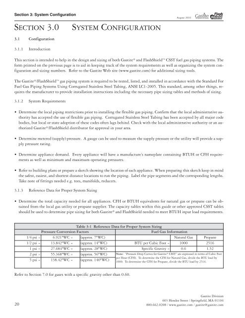
Section 3: System Configuration<br />
SE<strong>CT</strong>ION 3.0 SYSTEM CONFIGURATION<br />
3.1 Configuration<br />
3.1.1 Introduction<br />
20<br />
August 2010<br />
This section is intended to help in the design <strong>and</strong> sizing of both Gastite ® <strong>and</strong> FlashShield CSST fuel gas piping systems. The<br />
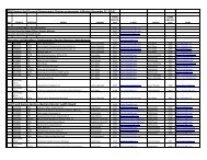
form printed on the previous page is to aid in keeping track of the system requirements as well as organizing the system configuration<br />
<strong>and</strong> sizing numbers. Refer to the Gastite Web site (www.gastite.com) for additional sizing tools.<br />
The Gastite ®/FlashShield gas piping system is required to be tested, listed, <strong>and</strong> installed in accordance with the St<strong>and</strong>ard For<br />
Fuel Gas Piping Systems Using Corrugated Stainless Steel Tubing, ANSI LC1-2005. This st<strong>and</strong>ard, among other things, requires<br />
the manufacturer to provide installation instructions including the necessary pipe sizing tables <strong>and</strong> methods of sizing.<br />
3.1.2 System Requirements<br />
Determine the local piping restrictions prior to installing the flexible gas piping. Confirm that the local administrative authority<br />
has accepted the use of flexible gas piping. Corrugated Stainless Steel Tubing has been accepted by all major code<br />
bodies, but local or state adoption of these codes often lags behind. Check with the local administrative authority or an authorized<br />
Gastite ®/FlashShield distributor for approval in your area.<br />
Determine metered (supply) pressure. A gauge can be used to measure the supply pressure or the utility will provide a supply<br />
pressure rating.<br />
Determine appliance dem<strong>and</strong>. Every appliance will have a manufacture’s nameplate containing BTUH or CFH requirements<br />
as well as minimum <strong>and</strong> maximum operating pressures.<br />
Refer to building plans or prepare a sketch showing the location of each appliance. When preparing this sketch keep in mind<br />
the safest, easiest, <strong>and</strong> shortest distance locations to run the piping. Label the pipe segments <strong>and</strong> the corresponding lengths.<br />
Take note of fittings needed e.g. tees, manifolds, reducers.<br />
3.1.3 Reference Data for Proper System Sizing<br />
Determine the total capacity needed for all appliances. CFH or BTUH equivalents for natural gas or propane can be obtained<br />
from the local gas utility or propane supplier. The capacity tables within this guide or other approved CSST tables<br />
should be used to determine pipe sizing for both Gastite ® <strong>and</strong> FlashShield needed to meet BTUH input load requirements.<br />
Table 3-1 Reference Data for Proper System Sizing<br />
Pressure Conversion Factors Fuel Gas Information<br />
1/4 psi = 6.921"WC = (approx. 7"WC) Natural Gas Propane<br />
1/2 psi = 13.842"WC = (approx. 14"WC) BTU per Cubic Foot = 1000 2516<br />
1 psi = 27.684"WC = (approx. 28"WC) Specific Gravity = 0.6 1.52<br />
2 psi = 55.368"WC = (approx. 56"WC) Note: “Pressure Drop Curves for Gastite ® CSST” are expressed in terms of Cubic Feet<br />
5 psi = 138.42"WC = (approx. 140"WC)<br />
per Hour (CFH). To determine the CFH for Natural Gas, divide the BTU load by<br />
1000. To determine the CFH for Propane, divide the BTU load by 2516.<br />
Refer to Section 7.0 for gases with a specific gravity other than 0.60.<br />
Gastite Division<br />
603 Hendee Street / Springfield, MA 01104<br />
800.662.0208 / www.gastite.com / gastite@gastite.com