Coupled-Mode Theory for Guided-Wave Optics
Coupled-Mode Theory for Guided-Wave Optics
Coupled-Mode Theory for Guided-Wave Optics

Create successful ePaper yourself
Turn your PDF publications into a flip-book with our unique Google optimized e-Paper software.
IEEE JOURNAL OF QUANTUM ELECTRONICS,<br />
VOL. QE-9, NO. 9, SEPTEMBER 1973 919<br />
<strong>Coupled</strong>-<strong>Mode</strong> <strong>Theory</strong> <strong>for</strong> <strong>Guided</strong>-<strong>Wave</strong> <strong>Optics</strong><br />
AMNON YARIV<br />
Absrruct-The problem of propagation and interaction of optical radia-<br />
tion in dielectric waveguides is cast in the coupled-mode <strong>for</strong>malism. This ap-<br />
proach is useful <strong>for</strong> treating problems involving energy exchange between<br />
modes. A derivation of the general theory is followed by application to the<br />
specific cases of electrooptic modulation, photoelastic and magnetooptic<br />
modulation, and optical filtering. Also treated are nonlinear optical<br />
applications such as second-harmonic generation in thin films and phase<br />
matching.<br />
A<br />
I. INTRODUCTION<br />
GROWING BODY of theoretical and experimental<br />
work has been recently building up in the area of<br />
guided-wave optics, which may be defined as the study and<br />
utilization of optical phenomena in thin dielectric<br />
waveguides [l], [2]. Some of this activity is due to the hopes<br />
11. THE COUPLED-MODE FORMALISM<br />
We will employ, in what follows, the coupled-mode <strong>for</strong>malism<br />
[X] to treat the various phenomena listed in Section I.<br />
Be<strong>for</strong>e embarking on a detailed analysis it will prove<br />
beneficial to consider some of the common features of this<br />
theory. Consider two electromagnetic modes with, in<br />
general, different frequencies whosecomplex amplitudes are<br />
A and B. These are taken as the eigenmodes of the unperturbed<br />
medium so that they represent propagating disturbances<br />
Manuscript received March 9, 1973. This research was supported in<br />
part by the National Science Foundation and in part by the Advanced<br />
Research Projects Agency through the Army Research Office, Durham,<br />
N.C.<br />
The author is with the Department of Electrical Engineering, Cali<strong>for</strong>nia<br />
Institute of Technology, Pasadena, Calif. 91109.<br />
with A and B constant.<br />
In the presence of a perturbation which, as an example,<br />
can take the place ofaperiodicelectricfield, asoundwave, or<br />
a surface corrugation, power is exchanged between modes a<br />
and 6. The complex amplitudes A and B in this case are no<br />
1ongerconstantbutwillbefoundtodependonz.Theywillbe<br />
shown below to obey relations of the type<br />
where the phase-mismatch constant A depends on the<br />
propagation constants Pa and P b as well as on the spatial<br />
variation of the coupling perturbation. The coupling<br />
<strong>for</strong> integrated optical circuits in which a number of optical<br />
functions will be per<strong>for</strong>med on small solid substrates with<br />
the interconnections provided by thin-film dielectric<br />
waveguides [3], [4]. Another reason <strong>for</strong> this interest is the coefficients K~~ and Kba are determined by the physical situapossibility<br />
of new nonlinear optical devices and efficient op- tion under consideration and their derivation will take up a<br />
tical modulators which are promised by this approach major part of this paper. Be<strong>for</strong>e proceeding, however, with<br />
[51-[71.<br />
the specific experimental situations, let us consider some<br />
A variety of theoretical ad hoc <strong>for</strong>malisms have been general features of the solutions of the coupled-mode<br />
utilized to datein treating thevarious phenomena ofguided- equations.<br />
wave optics. In this paper we present a unified theory cast in<br />
the coupled-mode <strong>for</strong>m to describe a large number of A. Codirectional Coupling<br />
seemingly diverse phenomena. These include: 1) nonlinear<br />
optical interactions; 2) phase matching by periodic perturbations;<br />
3) electrooptic switching and modulation; 4)<br />
photoelastic switching and modulation; 5) and optical filtering<br />
and reflection by a periodic perturbation.<br />
We take up, first, the case where modes a and b carry<br />
(Poynting) power in thesame direction. It is extremely convenient<br />
to define A and B in such a way that IA(z)( and<br />
I B(z)l correspond to the power carried by modes a and b,<br />
respectively. The conservation of total power is thus expressed<br />
as<br />
which, using (2), is satisfied when [9]<br />
If boundary conditions are such that single a mode, say b, is<br />
incident at z = 0 on the perturbed region z > 0, we have<br />
t 3)<br />
b(O)=B,, a(O)=O. (5)<br />
Subject to these conditions the solutions of (2) become
920 IEEE JOURNAL OF QUANTUM ELECTRONICS, SEPTEMBER 1973<br />
z=O 2.L<br />
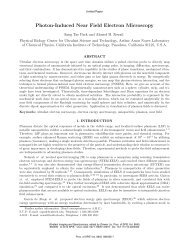
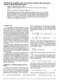
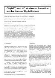
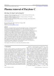
Fig. 1. The variation of the mode power in the case of codirectional Fig. 2. The transfer of power from an incident <strong>for</strong>ward wave B(z) to a<br />
coupling <strong>for</strong> phase-matched and unmatched operation. reflected wave A(z) in the case of contradirectional coupling.<br />
B(z) = BoeiA2/'{ cos [9(4~' + A2)'''zI the space betweenz = 0 andz = L. Sincemodeaisgenerated<br />
- A<br />
2<br />
(4K + A )<br />
sin [4(4,(' + ~ ' ) " ~ ~ z ] j (6)<br />
by the perturbation we have a(L) = 0. With these boundary<br />
conditions the solution of (1 1) is given by<br />
2iK,be-i(4.2/2)<br />
where K~ = I K =,,I 2. Under phase-matched condition A = 0, a A(Z) = B(O)<br />
sinh [f (z - L)]<br />
complete spatially periodic Ijower transfer between modesa -A sinh<br />
SL SL<br />
- f is cosh -<br />
and b takes place with a period ir/2K.<br />
2 2<br />
-i(Az/2)<br />
c<br />
B(z) = B(0) -<br />
SL SL<br />
-A sinh -- + is cosh -<br />
2 2<br />
b(=, t) = ~ ~ ~ ~ ( ~ b cos ~ -(KZ). @ b ~ )<br />
(7) -{A sinh [$ (z - L)] + is cosh<br />
A plot of the mode intensities 1 a1 and 1 bJ is shown in Fig.<br />
1. This figure demonstrates the fact that <strong>for</strong> phase mismatch<br />
A >> I K~,,[ the power exchange between the modes<br />
ble. Specific physical situations which are describable in<br />
terms of this picture will be discussed further below. Under phase-matching conditions A = 0 we have<br />
B. Contradirectional Coupling<br />
In this case the propagation in the unperturbed medium is<br />
described by<br />
is negligi- s E 44K2 - A', K E ]K,bI. (1 3)<br />
sinh [x(z - L)]<br />
A(z) = B(0) tf) -<br />
cosh (KL)<br />
cosh [K(Z - L)]<br />
B(z) = B(0) -<br />
cash (KL)<br />
(1 4)<br />
A plot of the mode powers 1 B(z)J and 1 A(z)J <strong>for</strong> this case<br />
(') is shown in Fig. 2. For sufficiently large arguments of the<br />
where A and B are constant. <strong>Mode</strong> a corresponds to a left<br />
(-z) traveling wave whileb travels to the right. A time-space<br />
periodic perturbation can lead to power exchange between<br />
the modes. Conservation of total power can expressed be as<br />
cosh and sinh functions in (14), the incident-mode power<br />
decays exponentially along the perturbation region. This<br />
decay, however, is due not to absorption but reflection to of<br />
power into the backward traveling mode a. This case will be<br />
considered in detail in following sections, where acoustoop-<br />
d<br />
- ( 1 AI2 - IBI') = 0<br />
dz<br />
(9)<br />
tic, electrooptic, and spatial will be<br />
treated. The exponential-decay behavior of Fig. 2 will be<br />
shown in Section VI11 to correspond to the stopband region<br />
which is satisfied by (2) if take we<br />
of periodic optical media.<br />
so that<br />
- dA = K,bBe-iAz dB = K,b*Ae"z<br />
dz dz<br />
(10) 111. ELECTROMAGNETIC DERIVATIONS<br />
OF THE COUPLED-<br />
MODE EQUATIONS<br />
A. TE <strong>Mode</strong>s<br />
(11) Consider the dielectric waveguide sketched in Fig. 3. It<br />
consists of a film of thickness t and index of refraction nz In this case we take the mode b with an amplitude B(0) to be sandwiched between media with indices n, and n,. Taking<br />
incident at z = 0 on the perturbation region which occupies (a/ay) = 0, this guide can, in the general case, support a
YARIV: COUPLED-MODE THEORY<br />
power flow of 1 A I W/m. The normalization condition is<br />
nl thus<br />
n2<br />
n3<br />
- propagation<br />
x=-t<br />
where the symbol m denotes themth confined TE mode cor-<br />
Fig. 3. The basic configuration of a slab dielectric waveguide. responding to mth eigenvalue of (19).<br />
Using (1 7) in (20) we determine<br />
finite number of confined TE modes with field components<br />
E,, H,, and Hz, andTMmodeswithcomponents H,, E,, and<br />
E,. The "radiation" modes of this structure<br />
(21)<br />
confined to the inner layer are not considered in this paper [P., (t + - 1 + --)(hm~ 1 + qmz),<br />
4m Pm<br />
and will be ignored. The field component E, of the TE<br />
modes, as an example, obeys wave the equation Since the modes are orthogonal we have<br />
which are not cM = 2hm y2.<br />
We take E,(x, z, t) in the <strong>for</strong>m B. TM <strong>Mode</strong>s<br />
Ey(x,z,l) =&y(x)e"wt-flz'. (16) The field components are<br />
I<br />
The transverse function &,,(x) is taken as<br />
COS (hx) - (q/h) sin (hx)],<br />
&"(X) = -t
922 IEEE JOURNAL OF QUANTUM ELECTRONICS, SEPTEMBER 1973<br />
2W€o<br />
dx = -<br />
Pn<br />
This condition determines the value of C, as [lo]<br />
I<br />
C. The Coupling Equation<br />
(27)<br />
The wave equation obeyed by the unperturbed modes is<br />
Multiplying (31) by &y(m)(x), and integrating and making<br />
use of the orthogonality relation (22) yields<br />
In this section we consider the exchange of power between<br />
a2E<br />
V2E(r, t) = pe -3 .<br />
at<br />
three modes of different frequencies brought about through<br />
the nonlinear optical properties of the guiding or bounding<br />
layers. The relevant experimental situations involve second-<br />
We will show below that in most of the experiments of innarmonic<br />
generation, frequency up-conversion, and optical<br />
terest to us we can represent the perturbation as a distributed<br />
parametric oscillation. To be specific we consider first the<br />
polarization source Ppert(r,t), which accounts <strong>for</strong> the deviacase<br />
of second-harmonic generation from an input mode at<br />
tion of the medium polarization from that which accompanies<br />
w/2 to an output mode w. The at perturbation polarization is<br />
the unperturbed mode. The wave equation <strong>for</strong> the perturbed<br />
taken as<br />
case follows directly from Maxwell's equations if we take D<br />
= coE + P.<br />
with similar equations <strong>for</strong> the remaining Cartesian components<br />
of E.<br />
We may take theeigenmodes of (28) as an orthonormal set<br />
in which to expand E, and write<br />
where A m(-j is the complex normal mode amplitude of the<br />
negative traveling TE mode while A m(+) is that of the positive<br />
one. Equation (32) is the main starting point <strong>for</strong> the following<br />
discussion in which we will consider a number of special<br />
cases.<br />
IV. NONLINEAR INTERACTIONS<br />
The complex amplitude of the polarization is<br />
where dijk("') is an element of the nonlinear optical tensor and<br />
summation over repeated indices is understood. We have<br />
allowed, in (34), <strong>for</strong> apossible dependence ofdij,ontheposition<br />
r.<br />
A. Case I: TEinpUt-TEoutpUt<br />
Without going, at this point, into considerations involving<br />
crystalline orientation, us let assume that an optical<br />
field parallel to the waveguide y direction will generate a<br />
where 1 extends over the discrete set of confined modes and second-harmonic polarization along the same direction<br />
includes both positive and negative traveling waves. The integration<br />
over /3 takes in the continuum of radiation modes,<br />
and C.C. denotes complex conjugation. Our chiefinterest lies<br />
in perturbations which couple only discrete modes so that, in<br />
where P and E represent complex amplitudes, and d<br />
what follows, we will neglect the second term on the right side<br />
corresponds to a linear combination of dijk which depends<br />
of (30). Problems of coupling to the radiation modes in arise<br />
on the crystal orientation. In this special case an input TE<br />
connection with waveguide losses [ 1 11 and grating couplers<br />
mode at w/2 will generate an output TE mode at w. Using<br />
P21.<br />
(30) in (35) gives<br />
Substituting (30) into (29), assuming "slow" variation so<br />
that d2Am/dz2
YARIV: COUPLED-MODE THEORY<br />
If we then use Py(r,t) as [Ppert(r, t)Jy in (32) we get<br />
with<br />
where we took d(r) = d(z)Ax),<br />
In the interest of conciseness let us consider the case where<br />
the inner layer 2 is nonlinear and where both the input and<br />
output modes are well confined. We thus have qm,pm >> h,<br />
sion results when the phase-matching condition<br />
and h,d = T. From (17) and (21) we get<br />
8-<br />
The overlap integral S(n,n,m) is maximum <strong>for</strong> n = m = 1, i.e.,<br />
fundamental mode operation both at w and 0/2. For this<br />
case the overlap integral becomes<br />
(39)<br />
and where the, now-superfluous, .mode-number subscripts<br />
have been dropped. Integrating (40) over the interaction distance<br />
1 gives<br />
The normalization condition (20) was chosen so that I A I<br />
is the power per unit width in the mode. We can thus rewrite<br />
Taking<br />
(42) as<br />
where we used ,P adz, E/€,, = n2. Note that (P12/wt) is<br />
the intensity (watts/square meter) of the input mode. Except<br />
<strong>for</strong> a numerical factor of 1.44, this expression is similar to<br />
that'derived <strong>for</strong> the bulk-crystal case'[ 131. Efficient conver-<br />
923<br />
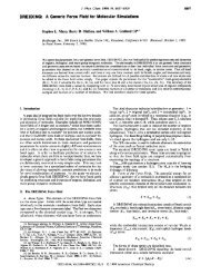
Fig. 4. The orientation of a 43m crystal <strong>for</strong> converting a TM input at<br />
w/2 to a TE wave at w. x, y, z are thedielectric-waveguide coordinates,<br />
while I, 2, and 3 are the crystalline axes. Top surface is (100):<br />
is satisfied. In this case the factor sin2 (Al/2)(A1/2l2 is<br />
unity. Phase-matching techniques will be discussed later.<br />
B. Case Ii: TMingut-TEoutput<br />
The anisotropy of the nonlinear optical properties can be<br />
used in such a way that the output at w is polarized<br />
orthogonally to the field of the input mode at w/2. To be<br />
specific, we co'nsider thecase of an input TM mode and an<br />
output TE mode. If, as an example, theguiding layer (or one<br />
of the bounding layers) belongs to the 43m crystal class<br />
(GaAs, CdTe, InAs), is it possible to have a guide geometry<br />
as shown in Fig. 4. x,y,z is the waveguide coordinate system<br />
as defined in Fig. 4, while 1,'2, and 3 are the conventional<br />
crystalline axes. For input TM mode with E I I x we have<br />
The nonlinear optical properties of a3m crystals are<br />
described by [13]<br />
so that<br />
and using (8Hy/8z) = -iwt E, gives
924 IEEE JOURNAL OF QUANTUM ELECTRONICS, 1973<br />
Using (45) and assuming a single, say m, mode input at tion<br />
w/2 results in<br />
of d by taking d(z) as<br />
P,(r, t) = - Lyv.-, Bm\-,-,K"\ 111, - / " I<br />
d<br />
d(z) = -t<br />
t("l-2Orn*/lZ) corresponding to a square-wave alternation between 0 andd<br />
.e + C.C.<br />
(47) with a period A . Instead of (37) we now have<br />
where We can choose the period A such that <strong>for</strong> value some of q<br />
and<br />
A = ( P n W ) - ~ ~ (PI~"~)TM.<br />
For the special casem = n = 1 and <strong>for</strong> well-confinedmodes<br />
we have, using (17) and (22),<br />
This results in a synchronous term (i.e,, onewith azero exponent)<br />
on the right side of (54) so that<br />
where the nonsynchronous terms have been neglected. A<br />
(50) comparison to (37) shows that the effective nonlinear<br />
coefficient is now reduced to<br />
Proceeding as in the previous section leads finally to d<br />
de,, = -<br />
4.rr<br />
an expression identical to that obtained in (43) <strong>for</strong> TE-TE<br />
conversion. We must recall, however, that the nonlinear<br />
P"<br />
~ pw/2 = 0.72 (:)<br />
coefficient din (5 1) is not necessarily the same as that appear- operation based on = 1 is thus most efficient, leading to a<br />
ing in (43), reflecting the differences in crystalline orientation reduction by a factor of R2 in the conversion efficiency, We<br />
needed to achieve coupling in each case. note, however, that the factor ~in~(A1/2)/(A1/2)~ is now<br />
unity, which makes it possible to take advantage of the l2<br />
C. Phase Matching dependence of the conversion efficiency.<br />
It follows from (43) or (51) that a necessary condition <strong>for</strong><br />
second-harmonic generation is A1/2
YAKIV: COUPLED-MODE THEORY<br />
It follows from (58) that an alternativeand equivalent definition<br />
would be to specify thechanges of the dielectric tensor ciJ<br />
as<br />
where the (0) superscript denotes a "low" frequency, i.e., a<br />
frequency well below the crystal's Reststrahl band. Using<br />
the relations<br />
and choosing a principal coordinate system so that<br />
Equation (67) is general enough to apply to a large variety<br />
where we used the convention ci = cii. The perturbation<br />
of cases. The dependence of E'"' and ~ (x, 2) on x allows <strong>for</strong><br />
polarization to be used in (32) is that part of Picw1 which is<br />
coupling by electrooptic material in the guiding or in the<br />
proportional to the "low"-frequency electric field, i.e.,<br />
bounding layers. The z dependence allows <strong>for</strong> situations<br />
where E'O' or Y depend on position. To be specific, we consider<br />
first the case where the guiding layer -t < x < 0 is<br />
uni<strong>for</strong>mly electrooptic and where E o ) is uni<strong>for</strong>m over the<br />
same region, so that the integration in (67) is from -t to 0.<br />
To bespecific, weassume that theinput isaTM modewith<br />
In that case, the overlap integral of (67) is maximum when<br />
E(W1 I I a, which is coupled by the electrooptic properties of the TE(m) and TM(I) modes are well confined and of the<br />
the bounding media or theguiding layer to theTEmodewith<br />
same order so that I = m. Under well-confined conditions<br />
ElW) 1 1 aY., The starting point is again (32) where the modem p, q >> h and the expressions (1 7) <strong>for</strong> E ~ ( ~ ) ( and X ) (24) <strong>for</strong><br />
corresponds to the output TEand [PpertIyis they component<br />
X $"'(x) in the guiding layer become<br />
of the polarization (61) induced by the x (and z*) electricfield<br />
components of the input TM mode. Using (61) weget<br />
py(w) = e.t.y..<br />
z 1 r1k I. tv 1. 12 Ek(0)<br />
where the I's are direction cosines. Defining<br />
(62) becomes<br />
where Py(W) is the complex amplitude of the polarization.<br />
In most cases of practical interest the choice of crystal<br />
orientation and the field is such as to simplify (63) to<br />
a simple <strong>for</strong>m resembling (64); an example is provided at<br />
the end of Section VI. In any case, the definition of (63)<br />
applies to the most general case.<br />
The E, component of a TM mode can also cause coupling but this will<br />
typically be a smaller effect, since E,
926<br />
while from (4)<br />
or using (7 1)<br />
IEEE JOURNAL OF QUANTUM ELECTRONICS, SEPTEMBER 1973<br />
<strong>for</strong> the coupling constant and the power-exchange<br />
distance, respectively.<br />
with<br />
VI. PHASE MATCHING IN ELECTROOPTIC COUPLING<br />
r~,~krE"'<br />
In general, pTM # pTE even <strong>for</strong> the same-order mode so<br />
K =<br />
2<br />
that the fraction of the power exchanged in the<br />
The <strong>for</strong>m of (70) will apply to the general case involving<br />
arbitrary spatial dependence of r and E''). In that case we<br />
need to per<strong>for</strong>m the integration in (67) to evaluate the<br />
coupling coefficient K.<br />
The <strong>for</strong>m of (70) is identical to that of (2). The solution<br />
of (70) is thus given by (6) with<br />
electrooptic-coupling case described previously does not<br />
exceed, according to (6), K'/(K' + A,). If A>> K, the COUpling<br />
is negligible. To appreciate the importance ofthis fact,<br />
let us use the numerical data of the example considered at<br />
the end of Section V. We have K = 1.85 cm-' and p n,k<br />
= 2.2 X lo5 cm-'. The exchange factor K'/(K' + A,) is thus<br />
reduced to 0.5 when A/p = [(BTE - &&&E] -<br />
The critical importance of phase matching is thus<br />
manifest. Since the dispersion due to the waveguide will in<br />
general be such as to make A >> K, some means <strong>for</strong> phase<br />
The transfer of power between the modes <strong>for</strong> the phase- matching are necessary. We start by considering again the<br />
matched (A = 0) and A # 0 case are as shown in Fig. 1. A coupled-mode equations (70), reintroducing the possible z<br />
complete transfer of power between the modes thus re- dependence of K<br />
quires that A = 0, i.e., phase matching. Means <strong>for</strong> phase<br />
matching will be discussed in Section VI. For the<br />
meantime let us, assume that K >> A so that, according to<br />
(6),. the effects of phase mismatch can be neglected. A complete<br />
power transfer in this case occurs in a distance 1 such<br />
that<br />
(74)<br />
(73)<br />
where A, = 27r/k. The product 1E is identical to the "halfwave"<br />
voltage of bulk electrooptic modulators [15]. The<br />
"half-voltage'' in the bulk case, we recall, is the fieldlength<br />
product which causes a 90" rotation in the plane of<br />
polarization of a wave incident on an electrooptic crystal.<br />
Unlike the bulk case, the coupling between the two<br />
guided modes can take place even when the electrooptic<br />
perturbation is limited to an arbitrarily small portion of<br />
the transverse dimensions [6] or when the two modes are<br />
of different order (1 # m).<br />
To appreciate the order of magnitude of the coupling,<br />
consider a case where the guiding layer is GaAs and X, = 1<br />
pm. In this case [15]<br />
Taking an applied field E = loe V/m we obtain from (7 1)<br />
K = 1.85 cm-'<br />
x<br />
1 = - = 0.85 cm<br />
2K<br />
K(Z) = n: kr(z) Co'(z).<br />
As in the case of second-harmonic generation, we can use a<br />
spatial modulation of Y or the field E',' <strong>for</strong> phase matching.<br />
Consider, <strong>for</strong> example, the case where the field E"'(z)<br />
reverses its direction periodically as with the electrode<br />
arrangement of Fig. 5. Approximating theelectric field in the<br />
guiding layer by<br />
(75)<br />
corresponding to afieldreversal between E,and - E,every A<br />
meters, we can take K(Z) in (74) as<br />
If we substitute (76) in (74) we obtain on the right-side<br />
terms with exponential dependence of the type<br />
One can choose A such that, <strong>for</strong> some q, (2q/A) = A. This<br />
results in a synchronous driving term (Le., one with azero ex-
YARIV: COUPLED-MODE THEORY 927<br />
w<br />
guiding layer<br />
Fig. 5. An interdigital-electrode structure <strong>for</strong> applying a spatially<br />
modulated electric field in electrooptic phase matching. x, y, and z are<br />
the waveguide coordinates, while 1, 2, and 3 refer to the cubic [IOO]<br />
axes of a $3171 crystal.<br />
ponent). To be specific, let us choose<br />
(77)<br />
and keeping only the synchronous term, obtain from (74)<br />
This corresponds to phase-matched operation with effec- an<br />
tive coupling coefficient reduced by ~ / relative 2 to phasematched<br />
operation with a uni<strong>for</strong>m field E(O)(z) = Eo. The<br />
solution of (78) is given by (7).<br />
We close this section by considering, again, the use of43m<br />
crystals <strong>for</strong> the phase-matching scheme just discussed. The<br />
nonvanishing elements of the iijk tensor are [ 151 raZ1 = rslz =<br />
r123. From (61) it follows directly that a43m crystal oriented,<br />
as in Fig. 5, so that its cubic 1,2,3 axescoincide, respectively,<br />
with thex,y,zdirectionsofthewaveguide,isoptimalsincein<br />
this case<br />
thus coupling theTE mode(E,'"') to theTM (Ex(")), andvice<br />
versa, in the presence of a longitudinal dc field E,(').<br />
Pijklisthephotoelastictensor.Comparing(79)to(58)wecan<br />
apply the results of Section V directly. Taking the strain field<br />
in the <strong>for</strong>m of<br />
we obtain in a manner similar to (61)<br />
<strong>for</strong> the polarization wave arising from the nonlinear mixing<br />
of an electric field<br />
and a sound strain wave (80).<br />
To be specific, we will assume again that the input optical<br />
field is a TM mode and will derive the equation governing the<br />
evolution of the TE mode due to the coupling. In a manner<br />
similar to (63) we abbreviate the in<strong>for</strong>mation relating to<br />
crystal symmetry and orientation by defining<br />
and instead of (81) use<br />
VII. PHOTOELASTIC COUPLING<br />
A few comments may be in order here. Each of the two<br />
The possibility Of dielectric-waveguide Optical<br />
terms on the right-hand side of (84) represents a traveling<br />
modes through the intermediary Of sound has been<br />
polarization wave. Both input waves, i.e., S(0) and Ex(@), we<br />
demonstrated [ 171. In thissectionwewill treat thisclassofin- recall, are taken as traveling in the +z direction. Orteractions<br />
using the coupled-mode <strong>for</strong>malism.<br />
dinarily, PTE is close to, but slightly larger than, PTM. In<br />
The photoelastic effect is defined by relating the effect of this the coupling is via the first term on the right side<br />
on theconstants oftheindexellipsoid through [I81 of (84) and the wavelength of the sound wave is adjusted<br />
so that<br />
(79)<br />
PTE = PTM + K
928 IEEE JOURNAL OF QUANTUM ELECTRONICS, SEPTEMBER 1973<br />
and the resulting TE mode is shifted up in frequency to3<br />
UTE ='w + R.<br />
Since the sign of PTE and PTM is the same, the coupling is<br />
codirectional. This is the case which we consider in detail<br />
below. Since K/P = (c/v,)(?/w), where us is the sound<br />
velocity, it is possible <strong>for</strong> reasonable values of the sound<br />
frequency Q to have K 2p. In this case the second term<br />
on the right side of (84) represents a polarization wave<br />
traveling in the -z direction with a phase velocity -w/(K<br />
- 0) = (-w/P). This wave is capable of coupling to the<br />
backward TE (or TM) mode. In this case we have<br />
Another possibility exists when the sound wave travels oppositely<br />
to the input TM mode. In this case we merely<br />
reverse the sign of K in (84). Codirectional coupling is now<br />
provided by the second term on the right side of (84) with<br />
where the fact that now wTE < w can be understood by<br />
noting that <strong>for</strong> each photon removed by the interaction<br />
from the input TM mode one new (negative traveling)<br />
phonon and one new TE photon are generated. Contradirectional<br />
coupling can take place due to the first term<br />
when<br />
Returning to the codirectional-coupling case represented<br />
by (85), we obtain, following the same steps leading to<br />
(70),<br />
where we assumed w >> Q. In the case of well-confined<br />
modes and of a photoelastic medium filling uni<strong>for</strong>mly the<br />
guiding region 2, the coupling constant, following the<br />
procedure leading to (71), is found to be<br />
which is similar to K of (71) except that the photoelastic<br />
constant p replaces r, the electrooptic constant, and a fac-<br />
tor of 2 appears in the denominator. The latter is due to<br />
the fact that the sound strain was taken as a time-har-<br />
monic field while, in the electrooptic case, the modulation<br />
field Eo' was taken as a dc field. The solution of (89) is<br />
given by (6) and illustrated by Fig. 1. Complete power<br />
transfer can take place only when A = 0, i.e., when<br />
Since K = Q/vs, this condition can be fulfilled by adjusting<br />
the sound frequency s2. Under phase-matched conditions<br />
we have, according to (6)<br />
with complete power exchange in a distance<br />
It is of interest to estimate the acoustic power needed to<br />
satisfy the switching condition (93). Solving (93) <strong>for</strong> the<br />
strain using (90) gives<br />
The corresponding acoustic intensity I (W/mz) can be obtained<br />
using the relation I = [(pvS3S2)/2] where p is the<br />
mass density. The result is<br />
where M = n6pz/pvs3 is the acoustic figure of merit [18].<br />
In a GaAs crystal, as an example, using the following<br />
data: M = 1O-I3, I = 5 mm, and an optical wavelength X,<br />
= 1 pm, we get<br />
The corresponding strain amplitude is<br />
where we used<br />
S(R' Y 2.3 x<br />
p = 5.34 g/cmS and us = 5.15 x los m/s.<br />
VIII. COUPLING BY A SURFACE CORRUGATION<br />
Consider an idealized dielectric waveguide such as that<br />
A qua,ntum mechanical analysis of this phenomenon 1191 shows that in Fig. 3. Let us next perturb the spatial distribution of n2<br />
in the section of the waveguide in which the TE mode grows, phonons<br />
combine with TM photons on a one to one basis to generate TE photons slightly from that shown in the figure. If the perturbation<br />
so that wTE = uTM + 0. is small is it useful to consider its effect in terms COU-<br />
of
YARIV: COUPLED-MODE THEORY 929<br />
z=o<br />
I<br />
z=L<br />
I<br />
Fig. 6. A corrugated dielectric waveguide.<br />
pling of the modes of the unperturbed system [ll]. In<br />
this section we will consider a perturbation due to a<br />
mechanical corrugation of the interface as shown in Fig. 6.<br />
Using the relation<br />
we get<br />
P = [c(r) - e,] E<br />
"2<br />
"3<br />
x=-t<br />
P,,,, = A4r) E(r, 2 ) = Anz(r) eo E(r, t) (95)<br />
where e(r) = n2(r)e0 so that coupling is only between TE or<br />
TM modes but not from TE to TM. To be specific, consider<br />
the case of a TE mode of order m propagating in the<br />
+z direction in a smooth waveguide. At z = 0 it encounters<br />
a corrugated region, as shown in Fig. 6, extending<br />
to z = L.<br />
Using (30) <strong>for</strong> Ey and limiting the summation to a single<br />
term 1 = rn gives upon substitution in (95)<br />
i(wt-Om2)<br />
.e + c.c.]. (96)<br />
We anticipate that the period A will be chosen so that<br />
2n/h = 2@, and the coupling will thus take place<br />
predominantly between the <strong>for</strong>ward and backward modes<br />
of order rn. Substituting (96) in (32) and limiting the left<br />
side of the latter to the backward A,(-) term gives<br />
From Fig. 6 we have<br />
1<br />
(97)<br />
An12(x, z) (98)<br />
\nZ2 - nI2, --a 5 x 5 o<br />
An2(x) =<br />
10, elsewhere<br />
7 = 2a/A. (99)<br />
Coupling from A,(+) to A,(-) occurs when, <strong>for</strong> some 1,<br />
In this case, keeping only the synchronous term, we obtain<br />
from (97) and (98)<br />
The next task is to evaluate the integral in (100). Using<br />
(99), the integral can be written as<br />
. la [cos @,x) - hm sin (h,x) 1' dx. (1 02)<br />
Although the integral in (102) can be calculated exactly using<br />
(19) and (21), an especially simple result ensues if we<br />
consider that operation is sufficiently above the propagation<br />
cutoff, so that q, >> h,.4 Per<strong>for</strong>ming the integration<br />
and assuming ha > h, so that (21)<br />
becomes<br />
Using P, 3 n2k, h, + r/t, and (104) in (103) leads to<br />
where 'Well above threshold q,/h, + (nzz - n,z)l/z (2t/X,).
930 IEEE JOURNAL OF QUANTUM ELECTRONICS, 1973<br />
which upon substitution into (100) gives<br />
and using (IO)<br />
dz<br />
d A:-)<br />
dz<br />
(-) -iAz<br />
KL = 31 n2<br />
= K1 A,(+)eiAz<br />
(105)<br />
(106)<br />
where 1, we recall, is the order of the (corrugation func-<br />
tion) harmonic responsible <strong>for</strong> the coupling, and X, =<br />
27r/k.<br />
-<br />
0.900 -<br />
Corrugation Helght: 0 =0.3pm<br />
Thlckness of wave guide: t = 3pm<br />
Refroctlve index of substrole:<br />
Periodicity: A arbitrary<br />
3.15 3.20<br />
Re (BA)<br />
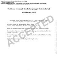
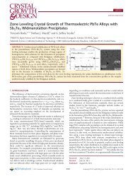
Fig. 7. A plot of the dispersion (kb versus PA) diagram in the vicinity of<br />
the optical gap.<br />
The behavior of the incident and reflected waves Am(+)<br />
U<br />
and Am(-] is given by (14) and is illustrated by Fig. 2 [in<br />
which the reflected wave is A(z) and the incident wave B(z)]. ..........................................<br />
The exponential decay behavior occurs only <strong>for</strong> a narrow<br />
range of frequencies which satisfy, according to (I3), the<br />
condition<br />
A Q - 2p(W) 7 2 K (107)<br />
--DI%lZ I<br />
IWl2-<br />
where 7 = 2n/A and we consider the case I = 1 only. This 0 L L<br />
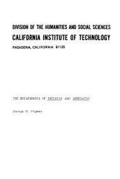
behavior is <strong>for</strong>mally analogous to Bragg scattering of Fig. 8. A theoretical plot of the transmission characteristics (12) of a<br />
Bloch electron waves in a crystal from one edge of the periodic waveguide near the Bragg (optical-gap) regime.<br />
Brillouin zone to the other by the crystal periodicity [20].<br />
The latter phenomenon is responsible <strong>for</strong> the appearance where mu and wL are the upper- and lower-gap frequencies,<br />
of <strong>for</strong>bidden energy gaps. The behavior of the corre- respectively.<br />
sponding optical gap can be elucidated by considering the The behavior of p‘ at w > mu and w < w1 is likewise<br />
total propagation constant of, say, the incident waveB(z) of derivable from (108). It is given <strong>for</strong> w > wu, as an example,<br />
(12) [A +(z) in the notation of this section]. From (8) and( 12)<br />
we can write it as<br />
by<br />
A S S<br />
2 2 2 2<br />
p’(w> = ~ (w) - - i - = 9 i -<br />
S == 4 4 K 2 - A’.<br />
The imaginary part of p‘ is then given by<br />
---<br />
‘v $2 - 32 (W<br />
C2<br />
- WO)’ (109)<br />
where w,, the midgap frequency, is defined by p(w0) = 17/2;<br />
and to get the second equality we approximated the unperturbed<br />
behavior of p by p(w) N (w/c)neff . The height of the<br />
energy gap is thus the frequency region over which ,8’ is<br />
complex. Using (109) it is given by<br />
*<br />
Equations (109) and (1 11) are valid <strong>for</strong> any coupling<br />
between the <strong>for</strong>ward and backward modes of a waveguide<br />
which is describable by a set of equations such as (105),<br />
regardless of the physical mechanism responsible <strong>for</strong> the<br />
coupling. As an illustration of the above ideas we chose to<br />
plot the w - @‘ diagram in the vicinity of the optical gap<br />
using the case of coupling by a surface corrugation.<br />
Referring to Fig. 7 we used d = 3 pm, A = 0.143 pm, a =<br />
0.3 pm, n, = 3.6, n3 = 3.4, n1 = 1, and took neff = nz. The<br />
midgap wavelength is X,[= (2ac/wo)] = 1 pm. The plot<br />
corresponding to (109) and (1 11) is dashed. The solid<br />
curves are the result of an “exact” analysis [21].<br />
The filtering properties [22] described above are illustrated<br />
in Fig. 8 which is a plot of the intensity transmission<br />
/B+(L)/B(O)I and reflection I A-(0)/B(O)12 as obtained<br />
from (12). The curves are plotted <strong>for</strong> KL = 1.84. The<br />
abscissa AL can also be approximated as above by AL =
YARIV: COUPLED-MODE THEORY<br />
[(un,/c) - 7/2]L. Fig. 8 thus describes the transmission as tion (32) results in<br />
a function of frequency (filtering) or, alternatively, as a<br />
function of the index nz. The latter can be tuned electrooptically,<br />
by temperature, photoelastically, or, in anisotropic<br />
media, by varying the propagation direction, thus offering<br />
some new possibilities <strong>for</strong> modulation and control.<br />
IX. MODE COUPLING BY WAVEGUIDE<br />
ANISOTROPY-MAGNETOOPTIC COUPLING<br />
If we examine the treatment of mode coupling by the<br />
electrooptic of photoelastic effects in Sections V and VII,<br />
we find that the coupling between TE and TM modes<br />
takes place whenever the dielectric tensor, expressed in<br />
terms of the waveguide-coordinate system x, y, z, has offdiagonal<br />
elements cry and czy. These off-diagonal elements<br />
can be induced by an external agency such as a sound<br />
wave or applied field. They can, however, be due to<br />
deviations of the waveguide material or its orientation<br />
from that which was assumed in deriving the behavior of<br />
the uncoupled TE and TM modes. In this case we can still<br />
describe the propagation in terms of coupling between the<br />
unperturbed TE or TM modes. This point of view is fruitful<br />
when the initial conditions correspond to either E, = 0<br />
(TE) or E, = 0 (TM). We can, alternatively, find the eigenmodes<br />
of the “perturbed” system as will be discussed in<br />
Section X.<br />
As a demonstration of this point of view we consider the<br />
propagation in a dielectric waveguide where one or more<br />
of the three layers is magnetic, if the direction of<br />
magnetization is parallel to the z direction. The dielectric<br />
tensor in the magnetized material is of the <strong>for</strong>m [23]<br />
- Ex<br />
5= eo<br />
-is 0 1<br />
0 is E, 0 E, 01 (1 12)<br />
Considering the off-diagonal elements of (1 12) as a pertur-<br />
bation we have<br />
so that a TM input will generate a perturbation polariza-<br />
tion<br />
E,‘”’<br />
2<br />
(P,,,,), = E,, -- exp [i(wt - PTMz)] + C.C.<br />
E*(w)<br />
= is exp [i(wt - &,@)I + C.C. (114)<br />
2<br />
Using (46) to expand E, in terms of the normal modes<br />
Bz Xy(z)(x),5 and substituting into the coupled-mode equa-<br />
We only keep one term in the expansion (46). This is the term <strong>for</strong><br />
PTMIf) N &‘m’<br />
93 1<br />
* exp [[(PTE - PTM)Zl (1 15)<br />
where A is the normal modk amplitude of the with TE<br />
mode, wh,ile B is that of the Ith TM mode. The offdiagonal<br />
element 6 is shown as an explicit function of position.<br />
Defining<br />
K = -- PTM Xu(L)(x)&,(m)(~) S(x, z) dx (116)<br />
the coupled-mode equations become<br />
A PTE - PTM. (1 17)<br />
The solutions of (1 17) correspond to the tiy now familiar<br />
case of codirectional exchange as given by (6).<br />
As an example, we calculate K <strong>for</strong> the case where the<br />
guiding layer is paramagnetic, and where the two coupled<br />
modes are similar (I = rn) and are well above cutoff.<br />
In a paramagnetic material the element 6 is proportional<br />
to the applied magnetic field H 1221<br />
6=- Xon V H<br />
7r<br />
where V is the Verdet constant of the material and where,<br />
in order to limit our attention to the magnetic effect, we<br />
take cx = cy = cz 3 e,,rz2. Well above cutoff we use (69) to<br />
evaluate the integral inside the square brackets of (1 15).<br />
[ 3Cu(z)(x)&u(L)(~)<br />
Using this result in (1 16)<br />
--I<br />
6(x, z) dx W 6 1 3Cy(z)&y(t)<br />
n6<br />
K = - = VH.<br />
nXn<br />
dx = 26.<br />
In case of,phase-matched operation (A = 0) with pure<br />
TM input, the solution of (1 17) is<br />
A = Bo sin KZ<br />
B = Bo COS KZ. (120)<br />
Since A( = PTE - PTM) is usually different from zero, some<br />
means <strong>for</strong> phase matching is necessary. One solution [24]<br />
is to reverse periodically the direction of H with a period<br />
2a/A. This method, which is analogous to that described
932 IEEE JOURNAL OF QUANTUM ELECTRONICS, SEPTEMBER 1973<br />
in Section VI, gives rise to a phase-matched operation with<br />
an effective coupling constant which, under square-wave<br />
variation of H, is smaller by a factor of 2/7r than that given<br />
by (1 19).<br />
X. THE EIGENMODES OF A PERTURBED WAVEGUIDE<br />
Up to this point we adopted the point of view of a per-<br />
turbation that couples the otherwise uncoupled TE and<br />
TM modes of a waveguide. This coupling, in the codirec-<br />
tional case, was shown on a number of occasions<br />
throughout this paper to lead to equations of the <strong>for</strong>m<br />
We recall that A and B are the normalized mode<br />
amplitudes and that the corresponding field variables vary<br />
as<br />
An alternative point of view is to find the eigenmodes of<br />
the-perturbed system, i.e., those linear combinations of<br />
A(z) and B(z] which, except <strong>for</strong> a propagation factor exp<br />
(iyz), are independent of z.<br />
We define a column vector as<br />
The evolution of B(z) is obtained from (121) and is<br />
described by<br />
with<br />
An eigenmode of the waveguide will have a solution of the<br />
<strong>for</strong>m<br />
Substituting this <strong>for</strong>m in (124) leads to two homogeneous<br />
equations <strong>for</strong> E, and E2<br />
- i(Pb -k y)E1 - K*E~ = 0<br />
KE, - i(p, -I- y)E2 = 0. (1 26)<br />
The solution of the resulting determinantal equation is<br />
I 2iK* I<br />
Note that 8, .E:,* and i?,.l?,* are the mode powers and<br />
that El .E,* = 0. The two components 2i~*/(A f S) and 1<br />
of each eigenvector represent the normalized amplitudes<br />
of the TE and TM components of each mode, so that the<br />
amount of admixture, i.e., the ratio of the powers in the<br />
two polarizations, is 4?/(A f S),. In the limit of K/A -+ 0,<br />
I?, and become<br />
3 ~ ~ ~ e - ~ ~ a z<br />
to within a multiplicative constant, and the eigenvectors<br />
become the uncoupled TE and TM modes. Another important<br />
consequence is that when A = 0, S = 2~ and the<br />
admixture is 50-50 percent, regardless of K. Even a more<br />
unconventional consequence is the fact that the two components<br />
E, and E, of each eigenvector do not, according to<br />
(122), correspond necessarily to fields of the same frequency.<br />
It is thus possible, as an example, when theperturbation<br />
is time periodic, to have an eigenmode traveling in a<br />
waveguide with<br />
while<br />
This is the case in photoelastic coupling by a traveling<br />
sound wave discussed in Section VII. What makes these<br />
strange bedfellows into a mode is the fact that they travel<br />
with the same phase factor, exp [-i(P - (S/2))z]. This<br />
phenomenon may be important in a laser oscillator which<br />
contains in its optical path a time-modulated coupling section.<br />
Let us, as an example, apply (129) to the case of<br />
magnetooptic coupling as discussed in Section IX. For this
YARIV: COUPLED-MODE THEORY<br />
case we have from (1 19) K =<br />
in the case A = 0 become<br />
E,(z) =<br />
VH, and the eigenmodes (1 29) Microwarje <strong>Theory</strong> Tech. (1968 Symposium Issue), vol. MTT-16, pp.<br />
1048-1054, Dec. 1968.<br />
[4] S. E. Miller, “Integrated optics, an introduction,” Bell Syst. Tech. J.<br />
vol. 48, p. 2059, 1969.<br />
[5] D. F. Nelson and R. K. Rinehart, “Light modulation by the electrooptic<br />
effect in reversed-biased GaP functions,” Appl. Phys. Lett.,<br />
1 vol. 5, p. 148, 1964.<br />
161 D. Hall, A. Yariv. and E. Garmire. “Ootical auidine and electrooo-<br />
$(z) = l ~ile-i;O+VHI* (131)<br />
.. - I<br />
tic modulation in GaAs epitaxial layers,” Opt. Commun., vol. 1, p.<br />
i.e., the well-known [22] circularly polarized modes. The<br />
403, 1970.<br />
[7] D. B. Anderson and J. T. Boyd, “Phase matched second harmonic<br />
generation in GaAs thin film waveguides,”Appl. Phys. Lett., vol. 19,<br />
p. 266, 1971.<br />
[8] J. R. Pierce, .‘‘Coupling of modes of propagation,” J. Appl. Phys.,<br />
angle of Faraday rotation in a distance z is<br />
vol. 25, p. 179, 1954.<br />
[9] A. Yariv, “On the coupling coefficients in the coupled-mode<br />
B(z) = VHZ. (132)<br />
theory,” Proc. IRE (Corresg.), vol. 46, pp. 1956-1957, Dec. 1958.<br />
[IO] A. Gover, private communication.<br />
[ 1 I] D. Marcuse, “<strong>Mode</strong> conversion caused by surface imperfections of a<br />
XI. SUMMARY<br />
dielectric slab waveguide,” vol. 48, p. 3187, 1969.<br />
[I21 M. L. Dakss, L. Kuhn, P. F. Heidrich, and B. A. Scott, “Grating<br />
We have applied the <strong>for</strong>malism of coupled modes<br />
describe a wide range of experimental situations ento<br />
coupler <strong>for</strong> efficient excitation of optical guided waves in thin films,”<br />
Appl. Phys. Lett., vol. 16, p. 523, 1970.<br />
[13] A. Yariv, Introduction to Optical Electronics. New York: Holt,<br />
countered in guided-wave optics. Explicit expressions <strong>for</strong><br />
the coupling coefficients, which play a central role in this<br />
theory, are given. The <strong>for</strong>malism treats the case of slab<br />
Rinehart and Winston. 1971, p. 190.<br />
[I41 S. Somekh and A. Yariv, “Phase matching by periodic modulation<br />
of the nonlinear optical properties,” Opt. Commuk., vol. 6, p. 301,<br />
1972.<br />
dielectric waveguides, thus assuming no variation in one<br />
(y) direction. The extension to guides where the confinement<br />
is in both the x and y directions principally involves<br />
[I51 See [13], ch. 9.<br />
[I61 J. F. Nye, Physical Properties of Crystals. New York: Ox<strong>for</strong>d<br />
University Press, 1957.<br />
[I71 L. Kuhn, M. L. Dakss, P. F. Heidrich, and B. A. Scott, “Deflection<br />
replacing the integration over all x in the expressions <strong>for</strong><br />
the coupling coefficients by an integration over both x and<br />
y. For cases where the modes are very well confined in the<br />
of optical guided waves by a surface acoustic wave,” Appl. Phys.<br />
Lett., vol. 17, p. 265, 1970.<br />
[I81 R. W. Dixon, “The photoelastic properties of selected materials and<br />
their relevance to acoustic light modulators and scanners,” J. Appl.<br />
y direction, the numerical correction is small.<br />
We have not discussed the applications of the coupledmode<br />
<strong>for</strong>malism to the distributed feedback laser [25], [26]<br />
and to directional coupling [27] since the original<br />
treatments are already cast in this <strong>for</strong>m.<br />
Phys., vol. 38, p. 5149, 1967.<br />
[I91 A. Yariv, “Quantum theory <strong>for</strong> parametric interactions of light and<br />
hypersound,” IEEE J. Quantum Electron., vol. QE-1, pp. 28-36,<br />
Apr. 1965.<br />
[20] C. Kittel, Introduction to Solid State Physics. New York: Wiley,<br />
4th ed., ch. 9.<br />
[21] K. Sakuda and A. Yariv, “Analysis of optical propagation in a cor-<br />
ACKNOWLEDGMENT<br />
rugated dielectric waveguide,” Opt. Commun., vol. 8, p. 1, 1973.<br />
[22] F. W. Dabby, A. Kestenbaum, and U. C. Paek, “Periodic dielectric<br />
waveguides,” Opt. Commun., vol. 6, p. 125, 1972; also F. W. Dabby,<br />
The author wishes to thank his colleagues, Dr. E. Garmire,<br />
Dr. K. Sakuda, and Dr. M. Nakamura, and his<br />
students, A. Gover, S. Somekh, and H. Stoll, <strong>for</strong> their<br />
M. A. Saifi, and A. Kestenbaum, “High frequency cutoff periodic<br />
dielectric waveguides,” Appl. Phys. Lett., vol. 22, p. 190, 1973.<br />
[23] W. J. Tabor, “Magnetooptic Materials” in Laser Handbook, F. T.<br />
Arecchi and E. 0. Schulz-Dubois, Eds. Amstyrdam, The<br />
numerous discussions and suggestions.<br />
Netherlands: North-Holland, 1972.<br />
1241 P. K. Tien, R. J. Martin, S. L. Blank, S. H. Wemple, and L. J.<br />
REFERENCES<br />
Varnerin, “Optical waveguides in single crystal garnet films,” Appl.<br />
Phys. Lett., vol. 21, p. 207, 1972.<br />
[25] H. Kogelnik and C. Y. Shank, “<strong>Coupled</strong> wave theory of distributed<br />
[I] A. Yariv and R. C. C. Leite, “Dielectric waveguide mode of light feedback lasers,” J. Appl. Phys., vol. 43, p. 2328, 1972.<br />
propagation in p-n junctions,” Appi. Phys. Lett., vol. 2, p. 55, 1963.<br />
[2] H. Osterberg and L. W. Smith, “Transmission of optical energy<br />
[26] P. Zory, “Laser oscillation in corrugated leaky optical<br />
waveguides,” to be published.<br />
along surfaces,” J. Opt. Soc. Amer., vol. 54, p. 1073, 1964. [27] S. Somekh, E. Garmire, A. Yariv, H. L. Garvin, and R. G.<br />
[3] R. Shubert and J. H. Harris, “Optical surface waves on thin films Hunsperger, “Channel optical waveguide directional couplers,”<br />
and their application to integrated data processors,” IEEE Truns. Appl. Phys. Lett., vol. 22, p. 46, 1972.<br />
933