2. Design of Welded Connections - Awssection.org
2. Design of Welded Connections - Awssection.org
2. Design of Welded Connections - Awssection.org

You also want an ePaper? Increase the reach of your titles
YUMPU automatically turns print PDFs into web optimized ePapers that Google loves.
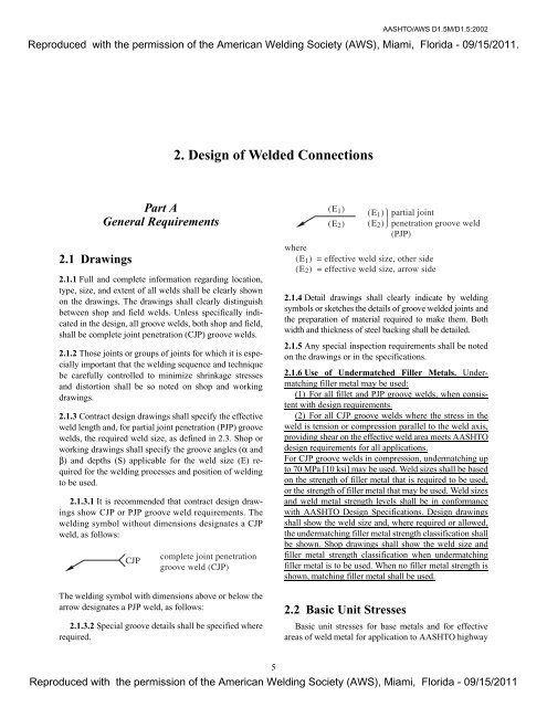
<strong>2.</strong>1 Drawings<br />
Part A<br />
General Requirements<br />
<strong>2.</strong>1.1 Full and complete information regarding location,<br />
type, size, and extent <strong>of</strong> all welds shall be clearly shown<br />
on the drawings. The drawings shall clearly distinguish<br />
between shop and field welds. Unless specifically indicated<br />
in the design, all groove welds, both shop and field,<br />
shall be complete joint penetration (CJP) groove welds.<br />
<strong>2.</strong>1.2 Those joints or groups <strong>of</strong> joints for which it is especially<br />
important that the welding sequence and technique<br />
be carefully controlled to minimize shrinkage stresses<br />
and distortion shall be so noted on shop and working<br />
drawings.<br />
<strong>2.</strong>1.3 Contract design drawings shall specify the effective<br />
weld length and, for partial joint penetration (PJP) groove<br />
welds, the required weld size, as defined in <strong>2.</strong>3. Shop or<br />
working drawings shall specify the groove angles (α and<br />
β) and depths (S) applicable for the weld size (E) required<br />
for the welding processes and position <strong>of</strong> welding<br />
to be used.<br />
<strong>2.</strong>1.3.1 It is recommended that contract design drawings<br />
show CJP or PJP groove weld requirements. The<br />
welding symbol without dimensions designates a CJP<br />
weld, as follows:<br />
The welding symbol with dimensions above or below the<br />
arrow designates a PJP weld, as follows:<br />
<strong>2.</strong>1.3.2 Special groove details shall be specified where<br />
required.<br />
5<br />
AASHTO/AWS D1.5M/D1.5:2002<br />
Reproduced with the permission <strong>of</strong> the American Welding Society (AWS), Miami, Florida - 09/15/2011.<br />
<strong>2.</strong> <strong>Design</strong> <strong>of</strong> <strong>Welded</strong> <strong>Connections</strong><br />
<strong>2.</strong>1.4 Detail drawings shall clearly indicate by welding<br />
symbols or sketches the details <strong>of</strong> groove welded joints and<br />
the preparation <strong>of</strong> material required to make them. Both<br />
width and thickness <strong>of</strong> steel backing shall be detailed.<br />
<strong>2.</strong>1.5 Any special inspection requirements shall be noted<br />
on the drawings or in the specifications.<br />
<strong>2.</strong>1.6 Use <strong>of</strong> Undermatched Filler Metals. Undermatching<br />
filler metal may be used:<br />
(1) For all fillet and PJP groove welds, when consistent<br />
with design requirements.<br />
(2) For all CJP groove welds where the stress in the<br />
weld is tension or compression parallel to the weld axis,<br />
providing shear on the effective weld area meets AASHTO<br />
design requirements for all applications.<br />
For CJP groove welds in compression, undermatching up<br />
to 70 MPa [10 ksi] may be used. Weld sizes shall be based<br />
on the strength <strong>of</strong> filler metal that is required to be used,<br />
or the strength <strong>of</strong> filler metal that may be used. Weld sizes<br />
and weld metal strength levels shall be in conformance<br />
with AASHTO <strong>Design</strong> Specifications. <strong>Design</strong> drawings<br />
shall show the weld size and, where required or allowed,<br />
the undermatching filler metal strength classification shall<br />
be shown. Shop drawings shall show the weld size and<br />
filler metal strength classification when undermatching<br />
filler metal is to be used. When no filler metal strength is<br />
shown, matching filler metal shall be used.<br />
<strong>2.</strong>2 Basic Unit Stresses<br />
Basic unit stresses for base metals and for effective<br />
areas <strong>of</strong> weld metal for application to AASHTO highway<br />
Reproduced with the permission <strong>of</strong> the American Welding Society (AWS), Miami, Florida - 09/15/2011
AASHTO/AWS D1.5M/D1.5:2002 DESIGN OF WELDED CONNECTIONS<br />
Reproduced with the permission <strong>of</strong> the American Welding Society (AWS), Miami, Florida - 09/15/2011.<br />
bridges shall be as shown in the AASHTO Standard<br />
Specifications for Highway Bridges or the AASHTO<br />
LRFD Bridge <strong>Design</strong> Specification.<br />
<strong>2.</strong>3 Effective Weld Areas, Lengths,<br />
Throats, and Sizes<br />
<strong>2.</strong>3.1 Groove Welds. The effective area shall be the effective<br />
weld length multiplied by the effective groove<br />
weld size.<br />
<strong>2.</strong>3.1.1 The effective weld length for any groove weld,<br />
square or skewed, shall be the width <strong>of</strong> the part joined,<br />
perpendicular to the direction <strong>of</strong> stress.<br />
<strong>2.</strong>3.1.2 The effective weld size <strong>of</strong> a CJP groove weld<br />
shall be the thickness <strong>of</strong> the thinner part joined. No increase<br />
is allowed for weld reinforcement.<br />
<strong>2.</strong>3.1.3 The effective weld size <strong>of</strong> a PJP groove weld<br />
shall be the depth <strong>of</strong> bevel less 3 mm [1/8 in.] for grooves<br />
having a groove angle less than 60° but not less than 45°<br />
at the root <strong>of</strong> the groove, when made by SMAW or SAW,<br />
when made in the vertical or overhead welding positions<br />
by GMAW or FCAW.<br />
The effective weld size <strong>of</strong> a PJP groove weld shall be<br />
the depth <strong>of</strong> bevel, without reduction, for grooves<br />
(1) having a groove angle <strong>of</strong> 60° or greater at the root<br />
<strong>of</strong> the groove when made by any <strong>of</strong> the following welding<br />
processes: SMAW, SAW, GMAW, FCAW, EGW, or<br />
ESW, or<br />
(2) having a groove angle not less than 45° at the root<br />
<strong>of</strong> the groove when made in flat or horizontal positions<br />
by GMAW or FCAW.<br />
<strong>2.</strong>3.1.4 Flare groove joints shall not be used to join<br />
structural steel in bridges.<br />
<strong>2.</strong>3.1.5 The minimum effective weld size <strong>of</strong> a PJP<br />
groove weld shall be as described in Table <strong>2.</strong><strong>2.</strong><br />
<strong>2.</strong>3.2 Fillet Welds. The effective area shall be the effective<br />
weld length multiplied by the effective throat. Stress<br />
in a fillet weld shall be considered as applied to this effective<br />
area, for any direction <strong>of</strong> applied load.<br />
<strong>2.</strong>3.<strong>2.</strong>1 The effective length <strong>of</strong> a fillet weld shall be<br />
the overall length <strong>of</strong> the full-size fillet, including boxing.<br />
No reduction in effective length shall be made for either<br />
the start or crater <strong>of</strong> the weld if the weld is full size<br />
throughout its length.<br />
6<br />
<strong>2.</strong>3.<strong>2.</strong>2 The effective length <strong>of</strong> a curved fillet weld<br />
shall be measured along the centerline <strong>of</strong> the effective<br />
throat. If the weld area <strong>of</strong> a fillet weld in a hole or slot<br />
computed from this length is greater than the area found<br />
from <strong>2.</strong>3.3, then this latter area shall be used as the effective<br />
area <strong>of</strong> the fillet weld.<br />
<strong>2.</strong>3.<strong>2.</strong>3 The minimum effective length <strong>of</strong> a fillet weld<br />
shall be at least four times the nominal size, or 40 mm<br />
[1-1/2 in.], whichever is greater.<br />
<strong>2.</strong>3.<strong>2.</strong>4 The effective throat shall be the shortest distance<br />
from the joint root to the weld face <strong>of</strong> the diagrammatic<br />
weld (see Annex I). Note: See Annex II for method<br />
<strong>of</strong> calculating effective throats for fillet welds in skewed<br />
T-joints. A convenient tabulation <strong>of</strong> relative leg sizes (W)<br />
for joints with zero root opening (R = 0) that will have<br />
the same strength as a 90° fillet weld has been provided<br />
for dihedral angles between 60° and 135° (see Annex II,<br />
Table II.1).<br />
<strong>2.</strong>3.3 Plug and Slot Welds. The effective area <strong>of</strong> a plug<br />
or slot weld shall be the nominal area <strong>of</strong> the hole or slot<br />
in the plane <strong>of</strong> the faying surface.<br />
<strong>2.</strong>3.4 The effective weld size <strong>of</strong> a combination PJP<br />
groove weld and a fillet weld shall be the shortest distance<br />
from the joint root to the weld face <strong>of</strong> the diagrammatic<br />
weld minus 3 mm [1/8 in.], for any groove detail<br />
requiring such deduction (see Annex I).<br />
<strong>2.</strong>4 General<br />
Part B<br />
Structural Details<br />
In general, stress concentrations should be avoided.<br />
This may be accomplished by sizing parts and <strong>org</strong>anizing<br />
components to minimize constraint against ductile behavior,<br />
and avoiding unnecessary concentrations <strong>of</strong> welds,<br />
particularly where there are short unwelded portions <strong>of</strong><br />
base metal between welds. Welds should not be larger<br />
than necessary. Welds should be sized to carry required<br />
loads at appropriate design stresses. Excess weld metal<br />
increases residual stress, and, when carried to extreme,<br />
may result in unacceptable distortion, cracks or lamellar<br />
tears. The <strong>org</strong>anization <strong>of</strong> parts in welded assemblies and<br />
details <strong>of</strong> welded joints shall afford ample access for the<br />
deposition <strong>of</strong> all required weld passes.<br />
Reproduced with the permission <strong>of</strong> the American Welding Society (AWS), Miami, Florida - 09/15/2011
DESIGN OF WELDED CONNECTIONS AASHTO/AWS D1.5M/D1.5:2002<br />
Reproduced with the permission <strong>of</strong> the American Welding Society (AWS), Miami, Florida - 09/15/2011.<br />
<strong>2.</strong>5 <strong>Welded</strong> Filler Plates<br />
<strong>2.</strong>5.1 <strong>Welded</strong> filler plates (see Figures <strong>2.</strong>1 and <strong>2.</strong>2) are<br />
designated Category E fatigue details and shall be<br />
avoided when joining tension and reversal <strong>of</strong> stress members.<br />
When the design allows the use <strong>of</strong> filler plates, they<br />
may be used in the following:<br />
(1) Splicing parts <strong>of</strong> different thicknesses<br />
(2) <strong>Connections</strong> that, due to existing geometric alignment,<br />
shall accommodate <strong>of</strong>fsets to allow simple framing<br />
<strong>2.</strong>5.2 A filler plate less than 6 mm [1/4 in.] thick shall not<br />
be used to transfer stress but shall be kept flush with the<br />
welded edges <strong>of</strong> the stress-carrying part. The sizes <strong>of</strong><br />
welds along such edges shall be increased over the required<br />
sizes by an amount equal to the thickness <strong>of</strong> the<br />
filler plate (see Figure <strong>2.</strong>1).<br />
<strong>2.</strong>5.3 Any filler plate 6 mm [1/4 in.] or more in thickness<br />
shall extend beyond the edges <strong>of</strong> the splice plate or connection<br />
material. It shall be welded to the part on which<br />
it is fitted, and the joint shall be <strong>of</strong> sufficient strength to<br />
transmit the splice plate or connection material stress applied<br />
at the surface <strong>of</strong> the filler plate as an eccentric load.<br />
The welds joining the splice plate or connection material<br />
to the filler plate shall be sufficient to transmit the splice<br />
plate or connection material stress and shall be long<br />
enough to avoid overstressing the filler plate along the<br />
toe <strong>of</strong> the weld (see Figure <strong>2.</strong>2).<br />
<strong>2.</strong>6 PJP Groove Welds<br />
PJP groove welds shall not be used where the applied<br />
tensile stress is normal to the effective throat <strong>of</strong> the weld.<br />
Joints containing PJP groove welds, made from one side<br />
only, shall be restrained to prevent rotation.<br />
Part C<br />
Details <strong>of</strong> <strong>Welded</strong> Joints<br />
<strong>2.</strong>7 Joint Qualification<br />
Details <strong>of</strong> welded joints that may be used in a prequalified<br />
WPS are described in <strong>2.</strong>8 through <strong>2.</strong>13.<br />
<strong>2.</strong>7.1 Joint details may depart from the details described<br />
in <strong>2.</strong>9 and <strong>2.</strong>10 only if the Contractor submits the proposed<br />
WPSs to the Engineer for approval, and at the<br />
Contractor’s expense, demonstrates their adequacy in<br />
conformance with the requirements <strong>of</strong> 5.13 <strong>of</strong> this code<br />
7<br />
and their conformance with applicable provisions <strong>of</strong> Sections<br />
3, 4, and 5.<br />
<strong>2.</strong>8 Details <strong>of</strong> Fillet Welds<br />
<strong>2.</strong>8.1 The details <strong>of</strong> fillet welds made by SMAW, SAW,<br />
GMAW, or FCAW to be used without WPS qualification<br />
under 5.13 are described in <strong>2.</strong>8.1.1 through <strong>2.</strong>8.1.5 and<br />
detailed in Figure <strong>2.</strong>3.<br />
<strong>2.</strong>8.1.1 The minimum fillet weld size, except for fillet<br />
welds used to reinforce groove welds, shall be as shown<br />
in Table <strong>2.</strong>1, or as calculated using procedures established<br />
to prevent cracking in conformance with 4.<strong>2.</strong><strong>2.</strong> In<br />
both cases, the minimum size shall apply if it is sufficient<br />
to satisfy design requirements.<br />
<strong>2.</strong>8.1.2 The maximum fillet weld size detailed along<br />
edges <strong>of</strong> material shall be the following:<br />
(1) The thickness <strong>of</strong> the base metal, for metal less<br />
than 6 mm [1/4 in.] thick (see Figure <strong>2.</strong>3, Detail A).<br />
(2) 2 mm [1/16 in.] less than the thickness <strong>of</strong> base<br />
metal, for metal 6 mm [1/4 in.] or more in thickness (see<br />
Figure <strong>2.</strong>3, Detail B), unless the weld is designated on<br />
the drawing to be built out to obtain full throat thickness.<br />
In the as-welded condition, the distance between the<br />
edge <strong>of</strong> the base metal and the toe <strong>of</strong> the weld may be<br />
more or less than 2 mm [1/16 in.], provided the weld size<br />
shall be clearly verifiable.<br />
<strong>2.</strong>8.1.3 Fillet welds in holes or slots in lap joints may<br />
be used to transfer shear or to prevent buckling or separation<br />
<strong>of</strong> lapped parts. These fillet welds may overlap, subject<br />
to the provisions <strong>of</strong> <strong>2.</strong>3.<strong>2.</strong><strong>2.</strong> Fillet welds in holes or<br />
slots are not to be considered as plug or slot welds.<br />
<strong>2.</strong>8.1.4 Fillet welds may be used in skewed T-joints<br />
having a dihedral angle (Ψ) <strong>of</strong> not less than 60° nor more<br />
than 135° (see Figure <strong>2.</strong>3, Details C and D). Detail D<br />
shall be used when R n would exceed 5 mm [3/16 in.]<br />
using Detail C.<br />
<strong>2.</strong>8.1.5 When the design allows intermittent fillet<br />
welds, the minimum length <strong>of</strong> an intermittent fillet weld<br />
shall be as described in <strong>2.</strong>3.<strong>2.</strong>3.<br />
<strong>2.</strong>8.1.6 Minimum spacing and dimensions <strong>of</strong> holes or<br />
slots when fillet welding is used shall conform to the requirements<br />
<strong>of</strong> <strong>2.</strong>9.<br />
<strong>2.</strong>8.1.7 Fillet welds which support a tensile force that<br />
is not parallel to the axis <strong>of</strong> the weld shall not terminate<br />
at the corners <strong>of</strong> parts or members, but shall be returned<br />
continuously, full size, around the corner for a length<br />
equal to twice the weld size where such return can be<br />
Reproduced with the permission <strong>of</strong> the American Welding Society (AWS), Miami, Florida - 09/15/2011
AASHTO/AWS D1.5M/D1.5:2002 DESIGN OF WELDED CONNECTIONS<br />
Reproduced with the permission <strong>of</strong> the American Welding Society (AWS), Miami, Florida - 09/15/2011.<br />
Note:<br />
1. The effective area <strong>of</strong> weld 2 shall equal that <strong>of</strong> weld 1, but its size shall be its effective size plus the<br />
thickness <strong>of</strong> the filler T.<br />
Figure <strong>2.</strong>1—Filler Plates Less Than 6 mm [1/4 in.] Thick (see <strong>2.</strong>5.1)<br />
Notes:<br />
1. The effective area <strong>of</strong> weld shall equal that <strong>of</strong> weld 1. The length <strong>of</strong> weld 2 shall be sufficient to<br />
avoid overstressing the filler plate in shear along planes x-x.<br />
<strong>2.</strong> The effective area <strong>of</strong> weld 3 shall at least equal that <strong>of</strong> weld 1 and there shall be no overstress<br />
<strong>of</strong> the ends <strong>of</strong> weld 3 resulting from the eccentricity <strong>of</strong> the forces acting on the filler plate.<br />
Figure <strong>2.</strong>2—Filler Plates 6 mm [1/4 in.] or Thicker (see <strong>2.</strong>5.3)<br />
8<br />
Reproduced with the permission <strong>of</strong> the American Welding Society (AWS), Miami, Florida - 09/15/2011
DESIGN OF WELDED CONNECTIONS AASHTO/AWS D1.5M/D1.5:2002<br />
Reproduced with the permission <strong>of</strong> the American Welding Society (AWS), Miami, Florida - 09/15/2011.<br />
General Note: (E)(n), (E’)(n) = effective throats dependent on magnitude <strong>of</strong> root opening (Rn) (see 3.3.1). Subscript (n) represents 1, 2, 3, or 4.<br />
Note:<br />
1. Angles smaller than 60° are allowed; however, in such cases, the weld is considered to be a PJP groove weld.<br />
Table <strong>2.</strong>1<br />
Minimum Fillet Weld Size 1, 2 (see <strong>2.</strong>8)<br />
Base Metal<br />
Thickness <strong>of</strong> Thicker<br />
Part Joined (T)<br />
Minimum<br />
Size <strong>of</strong><br />
Fillet Weld<br />
T ≤ 20 mm [3/4 in.] 6 mm [1/4 in.]0 Single-pass welds<br />
shall be used<br />
T > 20 mm [3/4 in.] 8 mm [5/16 in.]<br />
Notes:<br />
1. Smaller fillet welds may be approved by the Engineer based upon<br />
applied stress and the use <strong>of</strong> appropriate preheat.<br />
<strong>2.</strong> Except that the weld size need not exceed the thickness <strong>of</strong> the thinner<br />
part joined. For this exception, particular care should be taken to<br />
provide sufficient preheat to ensure weld soundness.<br />
Figure <strong>2.</strong>3— Details for Fillet Welds (see <strong>2.</strong>8.1)<br />
9<br />
made in the same plane. Boxing shall be indicated on design<br />
and detail drawings.<br />
<strong>2.</strong>8.1.8 Fillet welds deposited on the opposite sides <strong>of</strong><br />
a common plane <strong>of</strong> contact between two parts shall be<br />
interrupted at a corner common to both welds (see<br />
Figure <strong>2.</strong>6).<br />
<strong>2.</strong>9 Details <strong>of</strong> Plug and Slot Welds<br />
<strong>2.</strong>9.1 The details <strong>of</strong> plug and slot welds made by the<br />
SMAW, GMAW, or FCAW processes are described in<br />
<strong>2.</strong>9.2 through <strong>2.</strong>9.7 and 3.3.1.<br />
Reproduced with the permission <strong>of</strong> the American Welding Society (AWS), Miami, Florida - 09/15/2011
AASHTO/AWS D1.5M/D1.5:2002 DESIGN OF WELDED CONNECTIONS<br />
Reproduced with the permission <strong>of</strong> the American Welding Society (AWS), Miami, Florida - 09/15/2011.<br />
<strong>2.</strong>9.1.1 Plug and slot welds may be used without performing<br />
the WPS qualification described in 5.13, provided<br />
the technique provisions <strong>of</strong> 4.21, 4.22, and 4.23, as<br />
applicable, are met.<br />
<strong>2.</strong>9.2 The minimum diameter <strong>of</strong> the hole for a plug weld<br />
shall be no less than the thickness <strong>of</strong> the part containing<br />
it plus 8 mm [5/16 in.]. The maximum diameter shall<br />
equal the minimum diameter plus 3 mm [1/8 in.] or 2-1/4<br />
times the thickness <strong>of</strong> the member, whichever is greater.<br />
<strong>2.</strong>9.3 The minimum center-to-center spacing <strong>of</strong> plug<br />
welds shall be four times the diameter <strong>of</strong> the hole.<br />
<strong>2.</strong>9.4 The length <strong>of</strong> the slot for a slot weld shall not exceed<br />
ten times the thickness <strong>of</strong> the part containing it. The<br />
width <strong>of</strong> the slot shall be no less than the thickness <strong>of</strong> the<br />
part containing it plus 8 mm [5/16 in.]. The maximum<br />
width shall equal the minimum width plus 3 mm [1/8 in.]<br />
or 2-1/4 times the thickness <strong>of</strong> the member, whichever is<br />
greater.<br />
<strong>2.</strong>9.5 The ends <strong>of</strong> the slot shall be semicircular or shall<br />
have the corners rounded to a radius not less than the<br />
thickness <strong>of</strong> the part containing it, except those ends<br />
which extend to the edge <strong>of</strong> the part.<br />
<strong>2.</strong>9.6 The minimum spacing <strong>of</strong> lines <strong>of</strong> slot welds in a direction<br />
transverse to their length shall be four times the<br />
width <strong>of</strong> the slot. The minimum center-to-center spacing<br />
in a longitudinal direction on any line shall be two times<br />
the length <strong>of</strong> the slot.<br />
<strong>2.</strong>9.7 The depth <strong>of</strong> filling <strong>of</strong> plug or slot welds in metal<br />
16 mm [5/8 in.] thick or less shall be equal to the thickness<br />
<strong>of</strong> the material. In metal over 16 mm [5/8 in.] thick,<br />
it shall be at least one-half the thickness <strong>of</strong> the material,<br />
but no less than 16 mm [5/8 in.].<br />
<strong>2.</strong>10 Lap Joints<br />
<strong>2.</strong>10.1 The minimum overlap <strong>of</strong> parts in stress-carrying<br />
lap joints shall be five times the thickness <strong>of</strong> the thinner<br />
part. Unless lateral deflection <strong>of</strong> the parts is prevented,<br />
they shall be connected by at least two transverse lines <strong>of</strong><br />
fillet, plug, or slot welds or by two or more longitudinal<br />
fillet or slot welds.<br />
<strong>2.</strong>10.2 If longitudinal fillet welds are used alone in lap<br />
joints <strong>of</strong> end connections, the length <strong>of</strong> each fillet weld<br />
shall be no less than the perpendicular distance between<br />
the welds (shown as dotted line in Figure <strong>2.</strong>6). The transverse<br />
spacing <strong>of</strong> the welds shall not exceed 16 times the<br />
thickness <strong>of</strong> the connected thinner part unless suitable<br />
provision is made (as by intermediate plug or slot welds)<br />
to prevent buckling or separation <strong>of</strong> the parts. The longi-<br />
10<br />
tudinal fillet weld may be either at the edges <strong>of</strong> the member<br />
or in slots.<br />
<strong>2.</strong>10.3 When fillet welds in holes or slots are used, the<br />
clear distance from the edge <strong>of</strong> the hole or slot to the adjacent<br />
edge <strong>of</strong> the part containing it, measured perpendicular<br />
to the direction <strong>of</strong> stress, shall be no less than five<br />
times the thickness <strong>of</strong> the part nor less than two times the<br />
width <strong>of</strong> the hole or slot. The strength <strong>of</strong> the part shall be<br />
determined from the critical net section <strong>of</strong> the base<br />
metal.<br />
<strong>2.</strong>10.4 Lap joints are Category E details and should be<br />
avoided, when possible, in members subject to tension or<br />
reversal <strong>of</strong> stresses.<br />
<strong>2.</strong>11 Corner and T-Joints<br />
<strong>2.</strong>11.1 Corner and T-joints that are to be subjected to<br />
bending about an axis parallel to the joint shall have their<br />
welds arranged to avoid concentration <strong>of</strong> tensile stress at<br />
the root <strong>of</strong> any weld.<br />
<strong>2.</strong>11.2 Corner and T-joints parallel to the direction <strong>of</strong><br />
computed stress between components <strong>of</strong> built-up members<br />
designed for axial stress need not be CJP groove<br />
welds. Fillet welds or a combination <strong>of</strong> PJP welds and reinforcing<br />
fillet welds may be used.<br />
<strong>2.</strong>12 CJP Groove Welds<br />
<strong>2.</strong>1<strong>2.</strong>1 Dimensional Tolerances. Dimensions <strong>of</strong> groove<br />
welds specified on design or detailed drawings may vary<br />
as shown in Figure <strong>2.</strong>4.<br />
<strong>2.</strong>1<strong>2.</strong>2 Corner Joints. For corner joints using single-bevel<br />
groove welds, either plate may be bevelled, provided the<br />
basic groove configuration is not changed and adequate<br />
edge distance is maintained to support the welding operations<br />
without excessive melting. Joint preparation that<br />
bevels the plate that will be stressed in the short transverse<br />
direction will help to reduce lamellar tearing.<br />
<strong>2.</strong>13 PJP Groove Welds (see Figure <strong>2.</strong>5)<br />
<strong>2.</strong>13.1 Definition. Except as provided in Figure <strong>2.</strong>5,<br />
groove welds without steel backing, welded from one<br />
side, and groove welds welded from both sides but without<br />
backgouging, are considered PJP groove welds.<br />
Reproduced with the permission <strong>of</strong> the American Welding Society (AWS), Miami, Florida - 09/15/2011
DESIGN OF WELDED CONNECTIONS AASHTO/AWS D1.5M/D1.5:2002<br />
Reproduced with the permission <strong>of</strong> the American Welding Society (AWS), Miami, Florida - 09/15/2011.<br />
Legend for Figures <strong>2.</strong>4 and <strong>2.</strong>5<br />
Symbols for joint types<br />
B — butt joint<br />
C — corner joint<br />
T — T-joint<br />
BC — butt or corner joint<br />
TC — T- or corner joint<br />
BTC — butt, T-, or corner joint<br />
Symbols for base-metal thickness and penetration<br />
L — limited thickness– CJP<br />
U — unlimited thickness– CJP<br />
P — PJP<br />
Symbol for weld types<br />
1 — square-groove<br />
2 — single-V-groove<br />
3 — double-V-groove<br />
4 — single-bevel-groove<br />
5 — double-bevel-groove<br />
6 — single-U-groove<br />
7 — double-U-groove<br />
8 — single-J-groove<br />
9 — double-J-groove<br />
Symbols for welding processes if not SMAW<br />
S — SAW<br />
G — GMAW<br />
F — FCAW<br />
Welding processes<br />
SMAW — shielded metal arc welding<br />
GMAW — gas metal arc welding<br />
FCAW — flux cored metal arc welding<br />
SAW — submerged arc welding<br />
Welding positions<br />
F — flat<br />
H — horizontal<br />
V — vertical<br />
OH — overhead<br />
Dimensions<br />
R = Root Opening<br />
α, β = Groove Angles<br />
f = Root Face<br />
r = J- or U-groove Radius<br />
S, S 1, S 2 = PJP Groove Weld Depth <strong>of</strong> Groove<br />
E, E 1, E 2 = PJP Groove Weld Sizes corresponding to<br />
S, S 1, S 2, respectively<br />
Joint <strong>Design</strong>ation<br />
The lower case letters, e.g., a, b, c, etc., are used to differentiate<br />
between joints that would otherwise have the same joint<br />
designation.<br />
11<br />
Reproduced with the permission <strong>of</strong> the American Welding Society (AWS), Miami, Florida - 09/15/2011
AASHTO/AWS D1.5M/D1.5:2002 DESIGN OF WELDED CONNECTIONS<br />
Reproduced with the permission <strong>of</strong> the American Welding Society (AWS), Miami, Florida - 09/15/2011.<br />
Square-groove weld (1)<br />
Butt joint (B)<br />
Corner joint (C)<br />
Welding<br />
Process<br />
SMAW<br />
FCAW<br />
GMAW<br />
Square-groove weld (1)<br />
Butt joint (B)<br />
Welding<br />
Process<br />
Base Metal Thickness<br />
(U = unlimited)<br />
See Notes on Page 43<br />
Groove Preparation<br />
Figure <strong>2.</strong>4— Details <strong>of</strong> <strong>Welded</strong> Joints for CJP<br />
Groove Welds (see <strong>2.</strong>1<strong>2.</strong>1) (Dimensions in Millimeters)<br />
12<br />
Tolerances<br />
Allowed<br />
Welding<br />
Positions<br />
Gas<br />
Shielding<br />
for FCAW Notes<br />
Joint<br />
As Detailed As Fit-Up<br />
<strong>Design</strong>ation T1 T2 Root Opening (see <strong>2.</strong>1<strong>2.</strong>1) (see 3.3.4)<br />
B-L1a 6 max — R = T1 +2, – 0 +6, – 2 All — 1, 9<br />
C-L1a 6 max U R = T1 +2, – 0 +6, – 2 All — 1<br />
B-L1a-GF 10 max — R = T1 +2, – 0 +6, – 2 All<br />
Not<br />
required<br />
9<br />
Joint<br />
<strong>Design</strong>ation<br />
Base Metal Thickness<br />
(U = unlimited)<br />
T 1<br />
T 2<br />
Root Opening<br />
Groove Preparation<br />
As Detailed<br />
(see <strong>2.</strong>1<strong>2.</strong>1)<br />
Tolerances<br />
As Fit-Up<br />
(see 3.3.4)<br />
Allowed<br />
Welding<br />
Positions<br />
Gas<br />
Shielding<br />
for FCAW Notes<br />
SMAW B-L1b 6 max —<br />
T1 R = -----<br />
2<br />
+2, – 0 +2, – 3 All — 1, 3, 9<br />
GMAW<br />
FCAW<br />
B-L1b-GF 10 max — R = 0 to 3 +2, – 0 +2, – 3 All<br />
Not<br />
required<br />
3, 9<br />
SAW B-L1-S 10 max — R = 0 ±0 +2, – 0 F — 5, 9<br />
SAW B-L1a-S 16 max — R = 0 ±0 +2, – 0 F — 3, 9<br />
Reproduced with the permission <strong>of</strong> the American Welding Society (AWS), Miami, Florida - 09/15/2011
DESIGN OF WELDED CONNECTIONS AASHTO/AWS D1.5M/D1.5:2002<br />
Reproduced with the permission <strong>of</strong> the American Welding Society (AWS), Miami, Florida - 09/15/2011.<br />
Single-V-groove weld (2)<br />
Corner joint (C)<br />
Welding<br />
Process<br />
Joint<br />
<strong>Design</strong>ation<br />
Base Metal Thickness<br />
(U = unlimited)<br />
T 1<br />
SMAW C-U2 U U<br />
GMAW<br />
FCAW<br />
T 2<br />
C-U2-GF U U<br />
SAW C-U2b-S 25 min U<br />
Double-V-groove weld (3)<br />
Butt joint (B)<br />
Welding<br />
Process<br />
Joint<br />
<strong>Design</strong>ation<br />
Base Metal Thickness<br />
(U = unlimited)<br />
T 1<br />
α<br />
β<br />
T 2<br />
See Notes on Page 43<br />
Root Opening<br />
Root Face<br />
Groove Angle<br />
R = 0 to 3<br />
f = 0 to 3<br />
α = 60°<br />
R = 0 to 3<br />
f = 0 to 3<br />
α = 60°<br />
R = 0<br />
f = 6 max<br />
α = 60°<br />
Root Opening<br />
Root Face<br />
Groove Angle<br />
Groove Preparation<br />
Figure <strong>2.</strong>4 (Continued) (Millimeters)<br />
13<br />
As Detailed<br />
(see <strong>2.</strong>1<strong>2.</strong>1)<br />
+2, – 0<br />
+2, – 0<br />
+10°, – 0°<br />
+2, – 0<br />
+2, – 0<br />
+10°, – 0°<br />
±0<br />
+6, – 0<br />
+10°, – 0°<br />
Tolerances<br />
Groove Preparation<br />
As Detailed<br />
(see <strong>2.</strong>1<strong>2.</strong>1)<br />
Tolerances<br />
As Fit-Up<br />
(see 3.3.4)<br />
+2, – 3<br />
Not limited<br />
+10°, – 5°<br />
+2, – 3<br />
Not limited<br />
+10°, – 5°<br />
+2, – 0<br />
±2<br />
+10°, – 5°<br />
As Fit-Up<br />
(see 3.3.4)<br />
Allowed<br />
Welding<br />
Positions<br />
All —<br />
All<br />
Gas<br />
Shielding<br />
for FCAW Notes<br />
Not<br />
required<br />
1, 3, 6,<br />
12<br />
3, 6, 12<br />
F — 3, 6, 12<br />
For B-U3c-S only<br />
T1 S1 Over to<br />
50 60 35<br />
60 80 45<br />
80 90 55<br />
90 100 60<br />
100 120 70<br />
120 140 80<br />
140 160 95<br />
For T1 > 160 or T1 ≤ 50<br />
S1 = 2/3 (T1 – 6)<br />
Allowed<br />
Welding<br />
Positions<br />
Gas<br />
Shielding<br />
for FCAW Notes<br />
1, 3, 7,<br />
9<br />
Not<br />
3, 7, 9<br />
required<br />
SMAW B-U3b<br />
R = 0 to 3 +2, – 0 +2, – 3 All —<br />
GMAW<br />
FCAW<br />
B-U3-GF<br />
U — f = 0 to 3<br />
α = β = 60°<br />
+2, – 0<br />
+10°, – 0°<br />
Not limited<br />
+10°, – 5° All<br />
R = 0 +2, – 0 +2, – 0<br />
SAW B-U3c-S U —<br />
f = 6 min<br />
α = β = 60°<br />
+6, – 0<br />
+10°, – 0°<br />
+6, – 0<br />
+10°, – 5° F — 3, 7, 9<br />
To find S1 see table above: S2 = T1 – (S1 + f)<br />
Reproduced with the permission <strong>of</strong> the American Welding Society (AWS), Miami, Florida - 09/15/2011
AASHTO/AWS D1.5M/D1.5:2002 DESIGN OF WELDED CONNECTIONS<br />
Reproduced with the permission <strong>of</strong> the American Welding Society (AWS), Miami, Florida - 09/15/2011.<br />
Single-V-groove weld (2)<br />
Corner joint (C)<br />
Welding<br />
Process<br />
Joint<br />
<strong>Design</strong>ation<br />
SMAW C-U2a U U<br />
GMAW<br />
FCAW<br />
See Notes on Page 43<br />
Figure <strong>2.</strong>4 (Continued) (Millimeters)<br />
14<br />
As Detailed<br />
(see <strong>2.</strong>1<strong>2.</strong>1)<br />
Base Metal Thickness<br />
(U = unlimited) Groove Preparation Allowed<br />
Welding<br />
T1 T2 Root Opening Groove Angle Positions<br />
C-U2a-GF U U<br />
Tolerances<br />
As Fit-Up<br />
(see 3.3.4)<br />
R = +2, – 0 +6, – 2<br />
a = +10°, – 0° +10°, – 5°<br />
Gas<br />
Shielding<br />
for FCAW Notes<br />
R = 6 α = 45° All — 1, 12<br />
R = 10 α = 30° F, V, OH — 1, 12<br />
R = 12 α = 20° F, V, OH — 1, 12<br />
R = 5 α = 30° F, V, OH Required 12<br />
R = 10 α = 30° F, V, OH Not req. 12<br />
R = 6 α = 45° F, V, OH Not req. 12<br />
SAW C-L2a-S 50 max U R = 6 α = 30° F — 12<br />
SAW C-U2-S U U R = 16 α = 20° F — 12<br />
Single-V-groove weld (2)<br />
Butt joint (B)<br />
Welding<br />
Process<br />
Joint<br />
<strong>Design</strong>ation<br />
Base Metal Thickness<br />
(U = unlimited)<br />
T 1<br />
SMAW B-U2 U —<br />
GMAW<br />
FCAW<br />
SAW B-L2c-S<br />
B-U2-GF U —<br />
Over 12<br />
to 25<br />
Over 25<br />
to 38<br />
Over 38<br />
to 50<br />
α<br />
T 2<br />
—<br />
—<br />
—<br />
Root Opening<br />
Root Face<br />
Groove Angle<br />
R = 0 to 3<br />
f = 0 to 3<br />
α = 60°<br />
R = 0 to 3<br />
f = 0 to 3<br />
α = 60°<br />
R = 0<br />
f = 6 min<br />
α = 60°<br />
R = 0<br />
f = 10 min<br />
α = 60°<br />
R = 0<br />
f = 12 min<br />
α = 60°<br />
Groove Preparation<br />
As Detailed<br />
(see <strong>2.</strong>1<strong>2.</strong>1)<br />
+2, – 0<br />
+2, – 0<br />
+10°, – 0°<br />
+2, – 0<br />
+2, – 0<br />
+10°, – 0°<br />
R = ±0<br />
f = +6, – 0<br />
α = +10°, – 0°<br />
Tolerances<br />
As Fit-Up<br />
(see 3.3.4)<br />
+2, – 3<br />
Not limited<br />
+10°, – 5°<br />
+2, – 3<br />
Not limited<br />
+10°, – 5°<br />
+2, – 0<br />
Not limited<br />
+10°, – 5°<br />
Allowed<br />
Welding<br />
Positions<br />
Gas<br />
Shielding<br />
for FCAW Notes<br />
All — 1, 3, 9<br />
All<br />
Not<br />
required<br />
3, 9<br />
F — 3, 9<br />
Reproduced with the permission <strong>of</strong> the American Welding Society (AWS), Miami, Florida - 09/15/2011
DESIGN OF WELDED CONNECTIONS AASHTO/AWS D1.5M/D1.5:2002<br />
Reproduced with the permission <strong>of</strong> the American Welding Society (AWS), Miami, Florida - 09/15/2011.<br />
Square-groove weld (1)<br />
T-joint (T)<br />
Corner joint (C)<br />
Welding<br />
Process<br />
Joint<br />
<strong>Design</strong>ation<br />
Base Metal Thickness<br />
(U = unlimited)<br />
T 1<br />
T 2<br />
See Notes on Page 43<br />
Root Opening<br />
Groove Preparation<br />
Figure <strong>2.</strong>4 (Continued) (Millimeters)<br />
15<br />
As Detailed<br />
(see <strong>2.</strong>1<strong>2.</strong>1)<br />
Tolerances<br />
As Fit-Up<br />
(see <strong>2.</strong>1<strong>2.</strong>1)<br />
Allowed<br />
Welding<br />
Positions<br />
Gas<br />
Shielding<br />
for FCAW Notes<br />
SMAW TC-L1b 6 max U<br />
T1 R = -----<br />
2<br />
+2, – 0 +2, – 3 All — 1, 3, 6<br />
GMAW<br />
FCAW<br />
TC-L1-GF 10 max U R = 0 to 3 +2, – 0 +2, – 3 All<br />
Not<br />
required<br />
3, 6<br />
SAW TC-L1-S 10 max U R = 0 ±0 +2, – 0 F — 3, 6<br />
Single-V-groove weld (2)<br />
Butt joint (B)<br />
Welding<br />
Process<br />
Joint<br />
<strong>Design</strong>ation<br />
SMAW B-U2a U —<br />
GMAW<br />
FCAW<br />
As Detailed<br />
(see <strong>2.</strong>1<strong>2.</strong>1)<br />
Base Metal Thickness<br />
(U = unlimited) Groove Preparation Allowed<br />
Welding<br />
T1 T2 Root Opening Groove Angle Positions<br />
B-U2a-GF U —<br />
α<br />
Tolerances<br />
As Fit-Up<br />
(see 3.3.4)<br />
R = +2, – 0 +6, – 2<br />
α = +10°, – 0° +10°, – 5°<br />
Gas<br />
Shielding<br />
for FCAW Notes<br />
R = 6 α = 45° All — 1, 9<br />
R = 10 α = 30° F, V, OH — 1, 9<br />
R = 12 α = 20° F, V, OH — 1, 9<br />
R = 5 α = 30° F, V, OH Required 9<br />
R = 10 α = 30° F, V, OH Not req. 9<br />
R = 6 α = 45° F, V, OH Not req. 9<br />
SAW B-L2a-S 50 max — R = 6 α = 30° F — 9<br />
SAW B-U2-S U — R = 16 α = 20° F — 9<br />
Reproduced with the permission <strong>of</strong> the American Welding Society (AWS), Miami, Florida - 09/15/2011
AASHTO/AWS D1.5M/D1.5:2002 DESIGN OF WELDED CONNECTIONS<br />
Reproduced with the permission <strong>of</strong> the American Welding Society (AWS), Miami, Florida - 09/15/2011.<br />
Single-bevel-groove weld (4)<br />
Butt joint (B)<br />
Welding<br />
Process<br />
Joint<br />
<strong>Design</strong>ation<br />
SMAW B-U4a U —<br />
GMAW<br />
FCAW<br />
See Notes on Page 43<br />
Figure <strong>2.</strong>4 (Continued) (Millimeters)<br />
16<br />
As Detailed<br />
(see <strong>2.</strong>1<strong>2.</strong>1)<br />
Base Metal Thickness<br />
(U = unlimited) Groove Preparation Allowed<br />
Welding<br />
T1 T2 Root Opening Groove Angle Positions<br />
B-U4a-GF U —<br />
Single-bevel-groove weld (4)<br />
T-joint (T)<br />
Corner joint (C)<br />
Welding<br />
Process<br />
Joint<br />
<strong>Design</strong>ation<br />
SMAW TC-U4c U U<br />
GMAW<br />
FCAW<br />
α<br />
Tolerances<br />
As Fit-Up<br />
(see 3.3.4)<br />
R = +2, – 0 +6, – 2<br />
a = +10°, – 0° +10°, – 5°<br />
Gas<br />
Shielding<br />
for FCAW Notes<br />
R = 6 α = 45° F, H — 1, 9, 13<br />
R = 10 α = 30° F, H — 1, 9, 13<br />
R = 5 α = 30° H Required 9<br />
R = 6 α = 45° H Not req. 9<br />
R = 10 α = 30° H Not req. 9<br />
As Detailed<br />
(see <strong>2.</strong>1<strong>2.</strong>1)<br />
Base Metal Thickness<br />
(U = unlimited) Groove Preparation Allowed<br />
Welding<br />
T1 T2 Root Opening Groove Angle Positions<br />
TC-U4c-GF U U<br />
SAW TC-U4a-S U U<br />
α<br />
Tolerances<br />
As Fit-Up<br />
(see 3.3.4)<br />
R = +2, – 0 +6, – 2<br />
α = +10°, – 0° +10°, – 5°<br />
Gas<br />
Shielding<br />
for FCAW Notes<br />
R = 6 α = 45° All — 1, 12<br />
R = 10 α = 30° F, OH, H — 1, 12<br />
R = 5 α = 30° All Required 12<br />
R = 10 α = 30° F Not req. 12<br />
R = 6 α = 45° All Not req. 12<br />
R = 10<br />
R = 6<br />
α = 30°<br />
α = 45°<br />
F — 12<br />
Reproduced with the permission <strong>of</strong> the American Welding Society (AWS), Miami, Florida - 09/15/2011
DESIGN OF WELDED CONNECTIONS AASHTO/AWS D1.5M/D1.5:2002<br />
Reproduced with the permission <strong>of</strong> the American Welding Society (AWS), Miami, Florida - 09/15/2011.<br />
Single-bevel-groove weld (4)<br />
Butt (4) joint (B)<br />
Butt joint (B)<br />
Welding<br />
Process<br />
Joint<br />
<strong>Design</strong>ation<br />
Base Metal Thickness<br />
(U = unlimited)<br />
T 1<br />
T 2<br />
See Notes on Page 43<br />
Root Opening<br />
Groove Preparation<br />
Figure <strong>2.</strong>4 (Continued) (Millimeters)<br />
17<br />
As Detailed<br />
(see <strong>2.</strong>1<strong>2.</strong>1)<br />
Tolerances<br />
As Fit-Up<br />
(see 3.3.4)<br />
Allowed<br />
Welding<br />
Positions<br />
SMAW B-U4b U — R = 0 to 3 +2, – 0 +2, – 3 F, H —<br />
GMAW<br />
FCAW<br />
B-U4b-GF U —<br />
f = 0 to 3<br />
α = 45°<br />
+2, – 0<br />
+10°, – 0°<br />
Not limited<br />
10°, – 5° H<br />
Single-bevel-groove weld (4)<br />
T-joint (4) (T)<br />
Corner T-joint (T) joint (C)<br />
Corner joint (C)<br />
Welding<br />
Process<br />
Joint<br />
<strong>Design</strong>ation<br />
Base Metal Thickness<br />
(U = unlimited)<br />
T 1<br />
T 2<br />
α<br />
Root Opening<br />
Root Face<br />
Groove Angle<br />
Groove Preparation<br />
As Detailed<br />
(see <strong>2.</strong>1<strong>2.</strong>1)<br />
Tolerances<br />
As Fit-Up<br />
(see 3.3.4)<br />
Allowed<br />
Welding<br />
Positions<br />
Gas<br />
Shielding<br />
for FCAW Notes<br />
1, 3, 9,<br />
13<br />
Not<br />
3, 9<br />
required<br />
Gas<br />
Shielding<br />
for FCAW Notes<br />
1, 3, 6,<br />
12<br />
Not<br />
3, 6, 12<br />
required<br />
SMAW TC-U4b U U R = 0 to 3 +2, – 0 +2, – 3 All —<br />
GMAW<br />
FCAW<br />
TC-U4b-GF U U<br />
f = 0 to 3<br />
α = 45°<br />
+2, – 0<br />
+10°, – 0°<br />
Not limited<br />
10°, – 5° All<br />
R = 0<br />
±0<br />
+6, – 0<br />
SAW TC-U4b-S U U f = 3 max +0, – 3<br />
±2<br />
F — 3, 6, 12<br />
α = 60° +10°, – 0° 10°, – 5°<br />
Reproduced with the permission <strong>of</strong> the American Welding Society (AWS), Miami, Florida - 09/15/2011
AASHTO/AWS D1.5M/D1.5:2002 DESIGN OF WELDED CONNECTIONS<br />
Reproduced with the permission <strong>of</strong> the American Welding Society (AWS), Miami, Florida - 09/15/2011.<br />
Double-bevel-groove weld (5)<br />
Butt weld joint (5) (B)<br />
Butt joint (B)<br />
Welding<br />
Process<br />
Joint<br />
<strong>Design</strong>ation<br />
Base Metal Thickness<br />
(U = unlimited)<br />
T 1<br />
SMAW B-U5a U —<br />
GMAW<br />
FCAW<br />
B-U5-GF U —<br />
Double-bevel-groove weld (5)<br />
T-joint weld (5) (T)<br />
Corner T-joint (T) joint (C)<br />
Corner joint (C)<br />
Welding<br />
Process<br />
Joint<br />
<strong>Design</strong>ation<br />
α α<br />
β<br />
T 2<br />
Base Metal Thickness<br />
(U = unlimited)<br />
T 1<br />
T 2<br />
See Notes on Page 43<br />
Root Opening<br />
Root Face<br />
Groove Angle<br />
R = 0 to 3<br />
f = 0 to 3<br />
α = 45°<br />
β = 0° to 15°<br />
R = 0 to 3<br />
f = 0 to 3<br />
α = 45°<br />
β = 0° to 15°<br />
Root Opening<br />
Root Face<br />
Groove Angle<br />
Groove Preparation<br />
Figure <strong>2.</strong>4 (Continued) (Millimeters)<br />
18<br />
As Detailed<br />
(see <strong>2.</strong>1<strong>2.</strong>1)<br />
+2, – 0<br />
+2, – 0<br />
α β +10°<br />
– 0°<br />
+2, – 0<br />
+2, – 0<br />
α + β =<br />
+10°, – 0°<br />
Tolerances<br />
Groove Preparation<br />
As Detailed<br />
(see <strong>2.</strong>1<strong>2.</strong>1)<br />
Tolerances<br />
As Fit-Up<br />
(see 3.3.4)<br />
+2, – 3<br />
Not limited<br />
+ α β +10° +<br />
– 5°<br />
+2, – 3<br />
Not limited<br />
α + β =<br />
+10°, – 5°<br />
As Fit-Up<br />
(see 3.3.4)<br />
Allowed<br />
Welding<br />
Positions<br />
F, H —<br />
H<br />
Allowed<br />
Welding<br />
Positions<br />
Gas<br />
Shielding<br />
for FCAW Notes<br />
Not<br />
required<br />
1, 3, 7,<br />
9, 13<br />
3, 7, 9<br />
Gas<br />
Shielding<br />
for FCAW Notes<br />
1, 3, 6,<br />
7, 12<br />
SMAW TC-U5b U U R = 0 to 3 +2, – 0 +2, – 3 All —<br />
GMAW<br />
FCAW<br />
TC-U5-GF U U<br />
f = 0 to 3<br />
α = 45°<br />
+2, – 0<br />
+10°, – 0°<br />
Not limited<br />
+10°, – 5° All<br />
Not<br />
required<br />
R = 0<br />
±0<br />
+2, – 0<br />
SAW TC-U5-S U U f = 5 max +0, – 5<br />
±2<br />
F —<br />
α = 60° +10°, – 0° +10°, – 5°<br />
Reproduced with the permission <strong>of</strong> the American Welding Society (AWS), Miami, Florida - 09/15/2011<br />
3, 6, 7,<br />
12<br />
3, 6, 7,<br />
12
DESIGN OF WELDED CONNECTIONS AASHTO/AWS D1.5M/D1.5:2002<br />
Reproduced with the permission <strong>of</strong> the American Welding Society (AWS), Miami, Florida - 09/15/2011.<br />
Single-U-groove weld (6)<br />
Butt joint (B)<br />
Corner joint (C)<br />
Welding<br />
Process<br />
SMAW<br />
GMAW<br />
FCAW<br />
SAW<br />
See Notes on Page 43<br />
Base Metal Thickness<br />
(U = unlimited) Groove Preparation<br />
Figure <strong>2.</strong>4 (Continued) (Millimeters)<br />
19<br />
As Detailed<br />
(see <strong>2.</strong>1<strong>2.</strong>1)<br />
Tolerances<br />
As Fit-Up<br />
(see 3.3.4)<br />
R = +2, – 0 +2, – 3<br />
α = +10°, – 0° +10°, – 5°<br />
f = ±2 Not Limited<br />
r = +3, – 0 +3, – 0<br />
Allowed<br />
Welding<br />
Positions<br />
Gas<br />
Shielding<br />
for FCAW Notes<br />
Joint<br />
Groove Root Groove<br />
<strong>Design</strong>ation T1 T2 Root Opening Angle Face Radius<br />
B-U6 U U<br />
R = 0 to 3<br />
R = 0 to 3<br />
α = 45°<br />
α = 20°<br />
f = 3<br />
f = 3<br />
r = 6<br />
r = 6<br />
All<br />
F, OH<br />
—<br />
—<br />
1, 3, 9<br />
1, 3, 9<br />
C-U6 U U<br />
R = 0 to 3<br />
R = 0 to 3<br />
α = 45°<br />
α = 20°<br />
f = 3<br />
f = 3<br />
r = 6<br />
r = 6<br />
All<br />
F, OH<br />
—<br />
—<br />
1, 3, 12<br />
1, 3, 12<br />
B-U6-GF U U R = 0 to 3 α = 20° f = 3 r = 6 All Not req. 3, 9<br />
C-U6-GF U U R = 0 to 3 α = 20° f = 3 r = 6 All Not req. 3, 12<br />
B-U6-S 16 min 16 min R = 0 α = 20° f = 6 min r = 6 F — 3, 9<br />
C-U6-S 16 min 16 min R = 0 α = 20° f = 6 min r = 6 F — 3, 12<br />
Double-U-groove weld (7)<br />
Butt joint (B)<br />
Welding<br />
Process<br />
Joint<br />
<strong>Design</strong>ation<br />
Base Metal Thickness<br />
(U = unlimited) Groove Preparation<br />
T 1<br />
SMAW B-U7 U —<br />
α<br />
α<br />
T 2<br />
Root<br />
Opening<br />
Groove<br />
Angle<br />
Root<br />
Face<br />
Groove<br />
Radius<br />
As Detailed<br />
(see <strong>2.</strong>1<strong>2.</strong>1)<br />
Tolerances<br />
As Fit-Up<br />
(see 3.3.4)<br />
For B-U7 and B-U7-GF<br />
R = +2, – 0 +2, – 3<br />
α = +10°, – 0° +10°, – 5°<br />
f = ±2, – 0 Not Limited<br />
r = +6, – 0 ±2<br />
For B-U7-S<br />
R = ±0 +2, – 0<br />
f = +0, – 6 ±2<br />
Allowed<br />
Welding<br />
Positions<br />
R = 0 to 3 α = 45° f = 3 r = 6 All —<br />
R = 0 to 3 α = 20° f = 3 r = 6 F, OH —<br />
Gas<br />
Shielding<br />
for FCAW Notes<br />
1, 3, 7,<br />
9<br />
1, 3, 7,<br />
9<br />
Not<br />
3, 7, 9<br />
required<br />
GMAW<br />
FCAW<br />
B-U7-GF U — R = 0 to 3 α = 20° f = 3 r = 6 All<br />
SAW B-U7-S U — R = 0 α = 20° f = 6 max r = 6 F — 3, 7, 9<br />
Reproduced with the permission <strong>of</strong> the American Welding Society (AWS), Miami, Florida - 09/15/2011
AASHTO/AWS D1.5M/D1.5:2002 DESIGN OF WELDED CONNECTIONS<br />
Reproduced with the permission <strong>of</strong> the American Welding Society (AWS), Miami, Florida - 09/15/2011.<br />
Single-J-groove weld (8)<br />
Butt joint (B)<br />
Welding<br />
Process<br />
Joint<br />
<strong>Design</strong>ation<br />
See Notes on Page 43<br />
Base Metal Thickness<br />
(U = unlimited) Groove Preparation<br />
T 1<br />
T 2<br />
Root<br />
Opening<br />
Figure <strong>2.</strong>4 (Continued) (Millimeters)<br />
20<br />
Groove<br />
Angle<br />
Root<br />
Face<br />
Groove<br />
Radius<br />
As Detailed<br />
(see <strong>2.</strong>1<strong>2.</strong>1)<br />
Tolerances<br />
As Fit-Up<br />
(see 3.3.4)<br />
R = +2, – 0 +2, – 3<br />
α = +10°, – 0° +10°, – 5°<br />
f = +2, – 0 Not Limited<br />
r = +6, – 0 ±2<br />
Allowed<br />
Welding<br />
Positions<br />
SMAW B-U8 U — R = 0 to 3 α = 45° f = 3 r = 10 F, H —<br />
GMAW<br />
FCAW<br />
Single-J-groove weld (8)<br />
T-joint (T)<br />
Corner joint (C)<br />
Welding<br />
Process<br />
B-U8-GF U — R = 0 to 3 α = 30° f = 3 r = 10 H<br />
Joint<br />
<strong>Design</strong>ation<br />
Base Metal Thickness<br />
(U = unlimited) Groove Preparation<br />
T 1<br />
SMAW TC-U8a U U<br />
T 2<br />
Root<br />
Opening<br />
α<br />
Groove<br />
Angle<br />
Root<br />
Face<br />
Groove<br />
Radius<br />
As Detailed<br />
(see <strong>2.</strong>1<strong>2.</strong>1)<br />
Gas<br />
Shielding<br />
for FCAW Notes<br />
1, 3, 9,<br />
13<br />
Not<br />
3, 9<br />
required<br />
Tolerances<br />
As Fit-Up<br />
(see 3.3.4)<br />
R = +2, – 0 +2, – 3<br />
α = +10°, – 0° +10°, – 5°<br />
f = +2, – 0 Not Limited<br />
r = +6, – 0 ±2<br />
Allowed<br />
Welding<br />
Positions<br />
R = 0 to 3 α = 45° f = 3 r = 10 All —<br />
R = 0 to 3 α = 30° f = 3 r = 10 F, OH —<br />
Gas<br />
Shielding<br />
for FCAW Notes<br />
1, 3, 6,<br />
9<br />
1, 3, 6,<br />
9<br />
Not<br />
3, 6, 9<br />
required<br />
GMAW<br />
FCAW<br />
TC-U8a-GF U U R = 0 to 3 α = 30° f = 3 r = 10 All<br />
SAW TC-U8a-S 16 min 16 min R = 0 α = 30° f = 6 min r = 10 F — 3, 6, 9<br />
Reproduced with the permission <strong>of</strong> the American Welding Society (AWS), Miami, Florida - 09/15/2011
DESIGN OF WELDED CONNECTIONS AASHTO/AWS D1.5M/D1.5:2002<br />
Reproduced with the permission <strong>of</strong> the American Welding Society (AWS), Miami, Florida - 09/15/2011.<br />
Double-J-groove weld (9)<br />
Butt joint (B)<br />
Welding<br />
Process<br />
Joint<br />
<strong>Design</strong>ation<br />
See Notes on Page 43<br />
Base Metal Thickness<br />
(U = unlimited) Groove Preparation<br />
T 1<br />
T 2<br />
Root<br />
Opening<br />
Figure <strong>2.</strong>4 (Continued) (Millimeters)<br />
21<br />
Groove<br />
Angle<br />
Root<br />
Face<br />
Groove<br />
Radius<br />
As Detailed<br />
(see <strong>2.</strong>1<strong>2.</strong>1)<br />
Tolerances<br />
As Fit-Up<br />
(see 3.3.4)<br />
R = +2, – 0 +2, – 3<br />
α = +10°, – 0° +10°, – 5°<br />
f = +2, – 0 Not Limited<br />
r = +3, – 0 ±2<br />
Allowed<br />
Welding<br />
Positions<br />
SMAW B-U9 U — R = 0 to 3 α = 45° f = 3 r = 10 F, H —<br />
GMAW<br />
FCAW<br />
Double-J-groove weld (9)<br />
T-joint (T)<br />
Corner joint (C)<br />
Welding<br />
Process<br />
B-U9-GF U — R = 0 to 3 α = 30° f = 3 r = 10 H<br />
Joint<br />
<strong>Design</strong>ation<br />
Base Metal Thickness<br />
(U = unlimited) Groove Preparation<br />
T 1<br />
SMAW TC-U9a U U<br />
GMAW<br />
FCAW<br />
T 2<br />
Root<br />
Opening<br />
Groove<br />
Angle<br />
Root<br />
Face<br />
Groove<br />
Radius<br />
As Detailed<br />
(see <strong>2.</strong>1<strong>2.</strong>1)<br />
Gas<br />
Shielding<br />
for FCAW Notes<br />
1, 3, 7,<br />
9, 13<br />
Not<br />
3, 7, 9<br />
required<br />
Tolerances<br />
As Fit-Up<br />
(see 3.3.4)<br />
R = +2, – 0 +2, – 3<br />
α = +10°, – 0° +10°, – 5°<br />
f = +2, – 0 Not Limited<br />
r = +3, – 0 ±2<br />
Allowed<br />
Welding<br />
Positions<br />
R = 0 to 3 α = 45° f = 3 r = 10 All —<br />
R = 0 to 3 α = 30° f = 3 r = 10 F, OH —<br />
TC-U9a-GF U U R = 0 to 3 α = 30° f = 3 r = 10 All<br />
SAW TC-U9a-S 10 min 10 min R = 0 α = 30° f = 6 r = 10 F —<br />
α<br />
α<br />
Gas<br />
Shielding<br />
for FCAW Notes<br />
1, 3, 6,<br />
7, 12<br />
3, 6, 7,<br />
12<br />
Not 3, 6, 7,<br />
required 12<br />
3, 6, 7,<br />
12<br />
Reproduced with the permission <strong>of</strong> the American Welding Society (AWS), Miami, Florida - 09/15/2011
AASHTO/AWS D1.5M/D1.5:2002 DESIGN OF WELDED CONNECTIONS<br />
Reproduced with the permission <strong>of</strong> the American Welding Society (AWS), Miami, Florida - 09/15/2011.<br />
Square-groove weld (1)<br />
Butt joint (B)<br />
Corner joint (C)<br />
Welding<br />
Process<br />
SMAW<br />
FCAW<br />
GMAW<br />
Square-groove weld (1)<br />
Butt joint (B)<br />
Welding<br />
Process<br />
Base Metal Thickness<br />
(U = unlimited)<br />
See Notes on Page 43<br />
Groove Preparation<br />
Figure <strong>2.</strong>4 (Continued) (Inches)<br />
22<br />
Tolerances<br />
Allowed<br />
Welding<br />
Positions<br />
Gas<br />
Shielding<br />
for FCAW Notes<br />
Joint<br />
As Detailed As Fit-Up<br />
<strong>Design</strong>ation T1 T2 Root Opening (see <strong>2.</strong>1<strong>2.</strong>1) (see 3.3.4)<br />
B-L1a 1/4 max — R = T1 +1/16, – 0 +1/4, – 1/16 All — 1, 9<br />
C-L1a 1/4 max U R = T1 +1/16, – 0 +1/4, – 1/16 All — 1<br />
B-L1a-GF 3/8 max — R = T1 +1/16, – 0 +1/4, – 1/16 All<br />
Not<br />
required<br />
9<br />
Joint<br />
<strong>Design</strong>ation<br />
Base Metal Thickness<br />
(U = unlimited)<br />
T 1<br />
T 2<br />
Root Opening<br />
Groove Preparation<br />
As Detailed<br />
(see <strong>2.</strong>1<strong>2.</strong>1)<br />
Tolerances<br />
As Fit-Up<br />
(see 3.3.4)<br />
Allowed<br />
Welding<br />
Positions<br />
Gas<br />
Shielding<br />
for FCAW Notes<br />
SMAW B-L1b 1/4 max —<br />
T1 R = -----<br />
2<br />
+1/16, – 0 +1/16, – 1/8 All — 1, 3, 9<br />
GMAW<br />
FCAW<br />
B-L1b-GF 3/8 max — R = 0 to 1/8 +1/16, – 0 +1/16, – 1/8 All<br />
Not<br />
required<br />
3, 9<br />
SAW B-L1-S 3/8 max — R = 0 ±0 +1/16, – 0 F — 5, 9<br />
SAW B-L1a-S 5/8 max — R = 0 ±0 +1/16, – 0 F — 3, 9<br />
Reproduced with the permission <strong>of</strong> the American Welding Society (AWS), Miami, Florida - 09/15/2011
DESIGN OF WELDED CONNECTIONS AASHTO/AWS D1.5M/D1.5:2002<br />
Reproduced with the permission <strong>of</strong> the American Welding Society (AWS), Miami, Florida - 09/15/2011.<br />
Single-V-groove weld (2)<br />
Corner joint (C)<br />
Welding<br />
Process<br />
Joint<br />
<strong>Design</strong>ation<br />
Base Metal Thickness<br />
(U = unlimited)<br />
T 1<br />
SMAW C-U2 U U<br />
GMAW<br />
FCAW<br />
T 2<br />
C-U2-GF U U<br />
SAW C-U2b-S 1 min U<br />
Double-V-groove weld (3)<br />
Butt joint (B)<br />
Welding<br />
Process<br />
Joint<br />
<strong>Design</strong>ation<br />
Base Metal Thickness<br />
(U = unlimited)<br />
T 1<br />
α<br />
T 2<br />
β<br />
See Notes on Page 43<br />
Root Opening<br />
Root Face<br />
Groove Angle<br />
R = 0 to 1/8<br />
f = 0 to 1/8<br />
α = 60°<br />
R = 0 to 1/8<br />
f = 0 to 1/8<br />
α = 60°<br />
R = 0<br />
f = 1/4 max<br />
α = 60°<br />
Root Opening<br />
Root Face<br />
Groove Angle<br />
Groove Preparation<br />
Figure <strong>2.</strong>4 (Continued) (Inches)<br />
23<br />
As Detailed<br />
(see <strong>2.</strong>1<strong>2.</strong>1)<br />
+1/16, – 0<br />
+1/16, – 0<br />
+10°, – 0°<br />
+1/16, – 0<br />
+1/16, – 0<br />
+10°, – 0°<br />
±0<br />
+1/4, – 0<br />
+10°, – 0°<br />
Tolerances<br />
Groove Preparation<br />
As Detailed<br />
(see <strong>2.</strong>1<strong>2.</strong>1)<br />
Tolerances<br />
As Fit-Up<br />
(see 3.3.4)<br />
+1/16, – 1/8<br />
Not limited<br />
+10°, – 5°<br />
+1/16, – 1/8<br />
Not limited<br />
+10°, – 5°<br />
+1/16, – 0<br />
±1/16<br />
+10°, – 5°<br />
As Fit-Up<br />
(see 3.3.4)<br />
Allowed<br />
Welding<br />
Positions<br />
All —<br />
All<br />
Gas<br />
Shielding<br />
for FCAW Notes<br />
Not<br />
required<br />
1, 3, 6,<br />
12<br />
3, 6, 12<br />
F — 3, 6, 12<br />
For B-U3c-S only<br />
T1 S1 Over to<br />
2 2-1/2 1-3/8<br />
2-1/2 3 1-3/4<br />
3 3-5/8 2-1/8<br />
3-5/8 4 2-1/2<br />
4 4-3/4 2-3/4<br />
4-3/4 5-1/2 3<br />
5-1/2 6-1/4 3-3/4<br />
For T1 > 6-1/4 or T1 ≤ 2<br />
S1 = 2/3 (T1 – 1/4)<br />
Allowed<br />
Welding<br />
Positions<br />
Gas<br />
Shielding<br />
for FCAW Notes<br />
1, 3, 7,<br />
9<br />
Not<br />
3, 7, 9<br />
required<br />
SMAW B-U3b<br />
R = 0 to 1/8 +1/16, – 0 +1/16, – 1/8 All —<br />
GMAW<br />
FCAW<br />
B-U3-GF<br />
U — f = 0 to 1/8<br />
α = β = 60°<br />
+1/16, – 0<br />
+10°, – 0°<br />
Not limited<br />
+10°, – 5° All<br />
R = 0 +1/16, – 0 +1/16, – 0<br />
SAW B-U3c-S U —<br />
f = 1/4 min<br />
α = β = 60°<br />
+1/4, – 0<br />
+10°, – 0°<br />
+1/4, – 0<br />
+10°, – 5° F — 3, 7, 9<br />
To find S1 see table above: S2 = T1 – (S1 + f)<br />
Reproduced with the permission <strong>of</strong> the American Welding Society (AWS), Miami, Florida - 09/15/2011
AASHTO/AWS D1.5M/D1.5:2002 DESIGN OF WELDED CONNECTIONS<br />
Reproduced with the permission <strong>of</strong> the American Welding Society (AWS), Miami, Florida - 09/15/2011.<br />
Single-V-groove weld (2)<br />
Corner joint (C)<br />
Welding<br />
Process<br />
Joint<br />
<strong>Design</strong>ation<br />
SMAW C-U2a U U<br />
GMAW<br />
FCAW<br />
See Notes on Page 43<br />
Figure <strong>2.</strong>4 (Continued) (Inches)<br />
24<br />
As Detailed<br />
(see <strong>2.</strong>1<strong>2.</strong>1)<br />
Base Metal Thickness<br />
(U = unlimited) Groove Preparation Allowed<br />
Welding<br />
T1 T2 Root Opening Groove Angle Positions<br />
C-U2a-GF U U<br />
Tolerances<br />
As Fit-Up<br />
(see 3.3.4)<br />
R = +1/16, – 0 +1/4, – 1/16<br />
a = +10°, – 0° +10°, – 5°<br />
Gas<br />
Shielding<br />
for FCAW Notes<br />
R = 1/4 α = 45° All — 1, 12<br />
R = 3/8 α = 30° F, V, OH — 1, 12<br />
R = 1/2 α = 20° F, V, OH — 1, 12<br />
R = 3/16 α = 30° F, V, OH Required 12<br />
R = 3/8 α = 30° F, V, OH Not req. 12<br />
R = 1/4 α = 45° F, V, OH Not req. 12<br />
SAW C-L2a-S 2 max U R = 1/4 α = 30° F — 12<br />
SAW C-U2-S U U R = 5/8 α = 20° F — 12<br />
Single-V-groove weld (2)<br />
Butt joint (B)<br />
Welding<br />
Process<br />
Joint<br />
<strong>Design</strong>ation<br />
Base Metal Thickness<br />
(U = unlimited)<br />
T 1<br />
SMAW B-U2 U —<br />
GMAW<br />
FCAW<br />
SAW B-L2c-S<br />
B-U2-GF U —<br />
Over 1/2<br />
to 1<br />
Over 1<br />
to 1-1/2<br />
Over 1-1/2<br />
to 2<br />
α<br />
T 2<br />
—<br />
—<br />
—<br />
Root Opening<br />
Root Face<br />
Groove Angle<br />
R = 0 to 1/8<br />
f = 0 to 1/8<br />
α = 60°<br />
R = 0 to 1/8<br />
f = 0 to 1/8<br />
α = 60°<br />
R = 0<br />
f = 1/4 min<br />
α = 60°<br />
R = 0<br />
f = 3/8 min<br />
α = 60°<br />
R = 0<br />
f = 1/2 min<br />
α = 60°<br />
Groove Preparation<br />
As Detailed<br />
(see <strong>2.</strong>1<strong>2.</strong>1)<br />
+1/16, – 0<br />
+1/16, – 0<br />
+10°, – 0°<br />
+1/16, – 0<br />
+1/16, – 0<br />
+10°, – 0°<br />
R = ±0<br />
f = +1/4, – 0<br />
α = +10°, – 0°<br />
Tolerances<br />
As Fit-Up<br />
(see 3.3.4)<br />
+1/16, – 1/8<br />
Not limited<br />
+10°, – 5°<br />
+1/16, – 1/8<br />
Not limited<br />
+10°, – 5°<br />
+1/16, – 0<br />
Not limited<br />
+10°, – 5°<br />
Allowed<br />
Welding<br />
Positions<br />
Gas<br />
Shielding<br />
for FCAW Notes<br />
All — 1, 3, 9<br />
All<br />
Not<br />
required<br />
3, 9<br />
F — 3, 9<br />
Reproduced with the permission <strong>of</strong> the American Welding Society (AWS), Miami, Florida - 09/15/2011
DESIGN OF WELDED CONNECTIONS AASHTO/AWS D1.5M/D1.5:2002<br />
Reproduced with the permission <strong>of</strong> the American Welding Society (AWS), Miami, Florida - 09/15/2011.<br />
Square-groove weld (1)<br />
T-joint (T)<br />
Corner joint (C)<br />
Welding<br />
Process<br />
Joint<br />
<strong>Design</strong>ation<br />
Base Metal Thickness<br />
(U = unlimited)<br />
T 1<br />
T 2<br />
See Notes on Page 43<br />
Root Opening<br />
Groove Preparation<br />
Figure <strong>2.</strong>4 (Continued) (Inches)<br />
25<br />
As Detailed<br />
(see <strong>2.</strong>1<strong>2.</strong>1)<br />
Tolerances<br />
As Fit-Up<br />
(see <strong>2.</strong>1<strong>2.</strong>1)<br />
Allowed<br />
Welding<br />
Positions<br />
Gas<br />
Shielding<br />
for FCAW Notes<br />
SMAW TC-L1b 1/4 max U<br />
T1 R = -----<br />
2<br />
+1/16, – 0 +1/16, – 1/8 All — 1, 3, 6<br />
GMAW<br />
FCAW<br />
TC-L1-GF 3/8 max U R = 0 to 1/8 +1/16, – 0 +1/16, – 1/8 All<br />
Not<br />
required<br />
3, 6<br />
SAW TC-L1-S 3/8 max U R = 0 ±0 +1/16, – 0 F — 3, 6<br />
Single-V-groove weld (2)<br />
Butt joint (B)<br />
Welding<br />
Process<br />
Joint<br />
<strong>Design</strong>ation<br />
SMAW B-U2a U —<br />
GMAW<br />
FCAW<br />
As Detailed<br />
(see <strong>2.</strong>1<strong>2.</strong>1)<br />
Base Metal Thickness<br />
(U = unlimited) Groove Preparation Allowed<br />
Welding<br />
T1 T2 Root Opening Groove Angle Positions<br />
B-U2a-GF U —<br />
α<br />
Tolerances<br />
As Fit-Up<br />
(see 3.3.4)<br />
R = +1/16, – 0 +1/4, – 1/16<br />
α = +10°, – 0° +10°, – 5°<br />
Gas<br />
Shielding<br />
for FCAW Notes<br />
R = 1/4 α = 45° All — 1, 9<br />
R = 3/8 α = 30° F, V, OH — 1, 9<br />
R = 1/2 α = 20° F, V, OH — 1, 9<br />
R = 3/16 α = 30° F, V, OH Required 9<br />
R = 3/8 α = 30° F, V, OH Not req. 9<br />
R = 1/4 α = 45° F, V, OH Not req. 9<br />
SAW B-L2a-S 2 max — R = 1/4 α = 30° F — 9<br />
SAW B-U2-S U — R = 5/8 α = 20° F — 9<br />
Reproduced with the permission <strong>of</strong> the American Welding Society (AWS), Miami, Florida - 09/15/2011
AASHTO/AWS D1.5M/D1.5:2002 DESIGN OF WELDED CONNECTIONS<br />
Reproduced with the permission <strong>of</strong> the American Welding Society (AWS), Miami, Florida - 09/15/2011.<br />
Single-bevel-groove weld (4)<br />
Butt joint (B)<br />
Welding<br />
Process<br />
Joint<br />
<strong>Design</strong>ation<br />
SMAW B-U4a U —<br />
GMAW<br />
FCAW<br />
See Notes on Page 43<br />
Figure <strong>2.</strong>4 (Continued) (Inches)<br />
26<br />
As Detailed<br />
(see <strong>2.</strong>1<strong>2.</strong>1)<br />
Base Metal Thickness<br />
(U = unlimited) Groove Preparation Allowed<br />
Welding<br />
T1 T2 Root Opening Groove Angle Positions<br />
B-U4a-GF U —<br />
Single-bevel-groove weld (4)<br />
T-joint (T)<br />
Corner joint (C)<br />
Welding<br />
Process<br />
Joint<br />
<strong>Design</strong>ation<br />
SMAW TC-U4c U U<br />
GMAW<br />
FCAW<br />
α<br />
Tolerances<br />
As Fit-Up<br />
(see 3.3.4)<br />
R = +1/16, – 0 +1/4, – 1/16<br />
a = +10°, – 0° +10°, – 5°<br />
Gas<br />
Shielding<br />
for FCAW Notes<br />
R = 1/4 α = 45° F, H — 1, 9, 13<br />
R = 3/8 α = 30° F, H — 1, 9, 13<br />
R = 3/16 α = 30° H Required 9<br />
R = 1/4 α = 45° H Not req. 9<br />
R = 3/8 α = 30° H Not req. 9<br />
As Detailed<br />
(see <strong>2.</strong>1<strong>2.</strong>1)<br />
Base Metal Thickness<br />
(U = unlimited) Groove Preparation Allowed<br />
Welding<br />
T1 T2 Root Opening Groove Angle Positions<br />
TC-U4c-GF U U<br />
SAW TC-U4a-S U U<br />
α<br />
Tolerances<br />
As Fit-Up<br />
(see 3.3.4)<br />
R = +1/16, – 0 +1/4, – 1/16<br />
α = +10°, – 0° +10°, – 5°<br />
Gas<br />
Shielding<br />
for FCAW Notes<br />
R = 1/4 α = 45° All — 1, 12<br />
R = 3/8 α = 30° F, OH, H — 1, 12<br />
R = 3/16 α = 30° All Required 12<br />
R = 3/8 α = 30° F Not req. 12<br />
R = 1/4 α = 45° All Not req. 12<br />
R = 3/8<br />
R = 1/4<br />
α = 30°<br />
α = 45°<br />
F — 12<br />
Reproduced with the permission <strong>of</strong> the American Welding Society (AWS), Miami, Florida - 09/15/2011
DESIGN OF WELDED CONNECTIONS AASHTO/AWS D1.5M/D1.5:2002<br />
Reproduced with the permission <strong>of</strong> the American Welding Society (AWS), Miami, Florida - 09/15/2011.<br />
Single-bevel-groove weld (4)<br />
Butt (4) joint (B)<br />
Butt joint (B)<br />
Welding<br />
Process<br />
Joint<br />
<strong>Design</strong>ation<br />
Base Metal Thickness<br />
(U = unlimited)<br />
T 1<br />
T 2<br />
See Notes on Page 43<br />
Root Opening<br />
Groove Preparation<br />
Figure <strong>2.</strong>4 (Continued) (Inches)<br />
27<br />
As Detailed<br />
(see <strong>2.</strong>1<strong>2.</strong>1)<br />
Tolerances<br />
As Fit-Up<br />
(see 3.3.4)<br />
Allowed<br />
Welding<br />
Positions<br />
SMAW B-U4b U — R = 0 to 1/8 +1/16, – 0 +1/16, – 1/8 F, H —<br />
GMAW<br />
FCAW<br />
B-U4b-GF U —<br />
f = 0 to 1/8<br />
α = 45°<br />
+1/16, – 0<br />
+10°, – 0°<br />
Not limited<br />
10°, – 5° H<br />
Single-bevel-groove weld (4)<br />
T-joint (4) (T)<br />
Corner T-joint (T) joint (C)<br />
Corner joint (C)<br />
Welding<br />
Process<br />
Joint<br />
<strong>Design</strong>ation<br />
Base Metal Thickness<br />
(U = unlimited)<br />
T 1<br />
T 2<br />
α<br />
Root Opening<br />
Root Face<br />
Groove Angle<br />
Groove Preparation<br />
As Detailed<br />
(see <strong>2.</strong>1<strong>2.</strong>1)<br />
Tolerances<br />
As Fit-Up<br />
(see 3.3.4)<br />
Allowed<br />
Welding<br />
Positions<br />
Gas<br />
Shielding<br />
for FCAW Notes<br />
1, 3, 9,<br />
13<br />
Not<br />
3, 9<br />
required<br />
Gas<br />
Shielding<br />
for FCAW Notes<br />
1, 3, 6,<br />
12<br />
Not<br />
3, 6, 12<br />
required<br />
SMAW TC-U4b U U R = 0 to 1/8 +1/16, – 0 +1/16, – 1/8 All —<br />
GMAW<br />
FCAW<br />
TC-U4b-GF U U<br />
f = 0 to 1/8<br />
α = 45°<br />
+1/16, – 0<br />
+10°, – 0°<br />
Not limited<br />
10°, – 5° All<br />
R = 0<br />
±0 +1/4, – 0<br />
SAW TC-U4b-S U U f = 1/8 max +0, – 1/8 ±1/16<br />
F — 3, 6, 12<br />
α = 60° +10°, – 0° 10°, – 5°<br />
Reproduced with the permission <strong>of</strong> the American Welding Society (AWS), Miami, Florida - 09/15/2011
AASHTO/AWS D1.5M/D1.5:2002 DESIGN OF WELDED CONNECTIONS<br />
Reproduced with the permission <strong>of</strong> the American Welding Society (AWS), Miami, Florida - 09/15/2011.<br />
Double-bevel-groove weld (5)<br />
Butt weld joint (5) (B)<br />
Butt joint (B)<br />
Welding<br />
Process<br />
Joint<br />
<strong>Design</strong>ation<br />
Base Metal Thickness<br />
(U = unlimited)<br />
T 1<br />
SMAW B-U5a U —<br />
GMAW<br />
FCAW<br />
B-U5-GF U —<br />
Double-bevel-groove weld (5)<br />
T-joint weld (5) (T)<br />
Corner T-joint (T) joint (C)<br />
Corner joint (C)<br />
Welding<br />
Process<br />
Joint<br />
<strong>Design</strong>ation<br />
α α<br />
β<br />
T 2<br />
Base Metal Thickness<br />
(U = unlimited)<br />
T 1<br />
T 2<br />
See Notes on Page 43<br />
Root Opening<br />
Root Face<br />
Groove Angle<br />
R = 0 to 1/8<br />
f = 0 to 1/8<br />
α = 45°<br />
β = 0° to 15°<br />
R = 0 to 1/8<br />
f = 0 to 1/8<br />
α = 45°<br />
β = 0° to 15°<br />
Root Opening<br />
Root Face<br />
Groove Angle<br />
Groove Preparation<br />
Figure <strong>2.</strong>4 (Continued) (Inches)<br />
28<br />
As Detailed<br />
(see <strong>2.</strong>1<strong>2.</strong>1)<br />
+1/16, – 0<br />
+1/16, – 0<br />
α β +10°<br />
– 0°<br />
+1/16, – 0<br />
+1/16, – 0<br />
α + β =<br />
+10°, – 0°<br />
Tolerances<br />
Groove Preparation<br />
As Detailed<br />
(see <strong>2.</strong>1<strong>2.</strong>1)<br />
Tolerances<br />
As Fit-Up<br />
(see 3.3.4)<br />
+1/16, – 1/8<br />
Not limited<br />
+ α β +10° +<br />
– 5°<br />
+1/16, – 1/8<br />
Not limited<br />
α + β =<br />
+10°, – 5°<br />
As Fit-Up<br />
(see 3.3.4)<br />
Allowed<br />
Welding<br />
Positions<br />
F, H —<br />
H<br />
Allowed<br />
Welding<br />
Positions<br />
Gas<br />
Shielding<br />
for FCAW Notes<br />
Not<br />
required<br />
1, 3, 7,<br />
9, 13<br />
3, 7, 9<br />
Gas<br />
Shielding<br />
for FCAW Notes<br />
1, 3, 6,<br />
7, 12<br />
SMAW TC-U5b U U R = 0 to 1/8 +1/16, – 0 +1/16, – 1/8 All —<br />
GMAW<br />
FCAW<br />
TC-U5-GF U U<br />
f = 0 to 1/8<br />
α = 45°<br />
+1/16, – 0<br />
+10°, – 0°<br />
Not limited<br />
+10°, – 5° All<br />
Not<br />
required<br />
R = 0<br />
±0 +1/16, – 0<br />
SAW TC-U5-S U U f = 3/16 max +0, – 3/16 ±1/16<br />
F —<br />
α = 60° +10°, – 0° +10°, – 5°<br />
Reproduced with the permission <strong>of</strong> the American Welding Society (AWS), Miami, Florida - 09/15/2011<br />
3, 6, 7,<br />
12<br />
3, 6, 7,<br />
12
DESIGN OF WELDED CONNECTIONS AASHTO/AWS D1.5M/D1.5:2002<br />
Reproduced with the permission <strong>of</strong> the American Welding Society (AWS), Miami, Florida - 09/15/2011.<br />
Single-U-groove weld (6)<br />
Butt joint (B)<br />
Corner joint (C)<br />
Welding<br />
Process<br />
SMAW<br />
GMAW<br />
FCAW<br />
SAW<br />
See Notes on Page 43<br />
Base Metal Thickness<br />
(U = unlimited) Groove Preparation<br />
Figure <strong>2.</strong>4 (Continued) (Inches)<br />
29<br />
As Detailed<br />
(see <strong>2.</strong>1<strong>2.</strong>1)<br />
Tolerances<br />
As Fit-Up<br />
(see 3.3.4)<br />
R = +1/16, – 0 +1/16, – 1/8<br />
α = +10°, – 0° +10°, – 5°<br />
f = ±1/16 Not Limited<br />
r = +1/8, – 0 +1/8, – 0<br />
Allowed<br />
Welding<br />
Positions<br />
Gas<br />
Shielding<br />
for FCAW Notes<br />
Joint<br />
Groove Root Groove<br />
<strong>Design</strong>ation T1 T2 Root Opening Angle Face Radius<br />
B-U6 U U<br />
R = 0 to 1/8<br />
R = 0 to 1/8<br />
α = 45°<br />
α = 20°<br />
f = 1/8<br />
f = 1/8<br />
r = 1/4<br />
r = 1/4<br />
All<br />
F, OH<br />
—<br />
—<br />
1, 3, 9<br />
1, 3, 9<br />
C-U6 U U<br />
R = 0 to 1/8<br />
R = 0 to 1/8<br />
α = 45°<br />
α = 20°<br />
f = 1/8<br />
f = 1/8<br />
r = 1/4<br />
r = 1/4<br />
All<br />
F, OH<br />
—<br />
—<br />
1, 3, 12<br />
1, 3, 12<br />
B-U6-GF U U R = 0 to 1/8 α = 20° f = 1/8 r = 1/4 All Not req. 3, 9<br />
C-U6-GF U U R = 0 to 1/8 α = 20° f = 1/8 r = 1/4 All Not req. 3, 12<br />
B-U6-S 5/8 min 5/8 min R = 0 α = 20°<br />
f = 1/4<br />
min<br />
r = 1/4 F — 3, 9<br />
C-U6-S 5/8 min 5/8 min R = 0 α = 20°<br />
f = 1/4<br />
min<br />
r = 1/4 F — 3, 12<br />
Double-U-groove weld (7)<br />
Butt joint (B)<br />
Welding<br />
Process<br />
Joint<br />
<strong>Design</strong>ation<br />
Base Metal Thickness<br />
(U = unlimited) Groove Preparation<br />
T 1<br />
SMAW B-U7 U —<br />
GMAW<br />
FCAW<br />
T 2<br />
Root<br />
Opening<br />
Groove<br />
Angle<br />
Root<br />
Face<br />
Groove<br />
Radius<br />
As Detailed<br />
(see <strong>2.</strong>1<strong>2.</strong>1)<br />
Tolerances<br />
As Fit-Up<br />
(see 3.3.4)<br />
For B-U7 and B-U7-GF<br />
R = +1/16, – 0 +1/16, – 1/8<br />
α = +10°, – 0° +10°, – 5°<br />
f = ±1/16, – 0 Not Limited<br />
r = +1/4, – 0 ±1/16<br />
For B-U7-S<br />
R = ±0 +1/16, – 0<br />
f = +0, – 1/4 ±1/16<br />
Allowed<br />
Welding<br />
Positions<br />
R = 0 to 1/8 α = 45° f = 1/8 r = 1/4 All —<br />
R = 0 to 1/8 α = 20° f = 1/8 r = 1/4 F, OH —<br />
B-U7-GF U — R = 0 to 1/8 α = 20° f = 1/8 r = 1/4 All<br />
SAW B-U7-S U — R = 0 α = 20°<br />
α<br />
α<br />
f = 1/4<br />
max<br />
Gas<br />
Shielding<br />
for FCAW Notes<br />
1, 3, 7,<br />
9<br />
1, 3, 7,<br />
9<br />
Not<br />
3, 7, 9<br />
required<br />
r = 1/4 F — 3, 7, 9<br />
Reproduced with the permission <strong>of</strong> the American Welding Society (AWS), Miami, Florida - 09/15/2011
AASHTO/AWS D1.5M/D1.5:2002 DESIGN OF WELDED CONNECTIONS<br />
Reproduced with the permission <strong>of</strong> the American Welding Society (AWS), Miami, Florida - 09/15/2011.<br />
Single-J-groove weld (8)<br />
Butt joint (B)<br />
Welding<br />
Process<br />
Joint<br />
<strong>Design</strong>ation<br />
See Notes on Page 43<br />
Base Metal Thickness<br />
(U = unlimited) Groove Preparation<br />
T 1<br />
T 2<br />
Root<br />
Opening<br />
Figure <strong>2.</strong>4 (Continued) (Inches)<br />
30<br />
Groove<br />
Angle<br />
Root<br />
Face<br />
Groove<br />
Radius<br />
As Detailed<br />
(see <strong>2.</strong>1<strong>2.</strong>1)<br />
Tolerances<br />
As Fit-Up<br />
(see 3.3.4)<br />
R = +1/16, – 0 +1/16, – 1/8<br />
α = +10°, – 0° +10°, – 5°<br />
f = +1/16, – 0 Not Limited<br />
r = +1/4, – 0 ±1/16<br />
Allowed<br />
Welding<br />
Positions<br />
SMAW B-U8 U — R = 0 to 1/8 α = 45° f = 1/8 r = 3/8 F, H —<br />
GMAW<br />
FCAW<br />
Single-J-groove weld (8)<br />
T-joint (T)<br />
Corner joint (C)<br />
Welding<br />
Process<br />
B-U8-GF U — R = 0 to 1/8 α = 30° f = 1/8 r = 3/8 H<br />
Joint<br />
<strong>Design</strong>ation<br />
Base Metal Thickness<br />
(U = unlimited) Groove Preparation<br />
T 1<br />
SMAW TC-U8a U U<br />
GMAW<br />
FCAW<br />
T 2<br />
Root<br />
Opening<br />
Groove<br />
Angle<br />
Root<br />
Face<br />
Groove<br />
Radius<br />
As Detailed<br />
(see <strong>2.</strong>1<strong>2.</strong>1)<br />
Gas<br />
Shielding<br />
for FCAW Notes<br />
1, 3, 9,<br />
13<br />
Not<br />
3, 9<br />
required<br />
Tolerances<br />
As Fit-Up<br />
(see 3.3.4)<br />
R = +1/16, – 0 +1/16, – 1/8<br />
α = +10°, – 0° +10°, – 5°<br />
f = +1/16, – 0 Not Limited<br />
r = +1/4, – 0 ±1/16<br />
Allowed<br />
Welding<br />
Positions<br />
R = 0 to 1/8 α = 45° f = 1/8 r = 3/8 All —<br />
R = 0 to 1/8 α = 30° f = 1/8 r = 3/8 F, OH —<br />
TC-U8a-GF U U R = 0 to 1/8 α = 30° f = 1/8 r = 3/8 All<br />
SAW TC-U8a-S 5/8 min 5/8 min R = 0 α = 30°<br />
α<br />
f = 1/4<br />
min<br />
Gas<br />
Shielding<br />
for FCAW Notes<br />
1, 3, 6,<br />
9<br />
1, 3, 6,<br />
9<br />
Not<br />
3, 6, 9<br />
required<br />
r = 3/8 F — 3, 6, 9<br />
Reproduced with the permission <strong>of</strong> the American Welding Society (AWS), Miami, Florida - 09/15/2011
DESIGN OF WELDED CONNECTIONS AASHTO/AWS D1.5M/D1.5:2002<br />
Reproduced with the permission <strong>of</strong> the American Welding Society (AWS), Miami, Florida - 09/15/2011.<br />
Double-J-groove weld (9)<br />
Butt joint (B)<br />
Welding<br />
Process<br />
Joint<br />
<strong>Design</strong>ation<br />
See Notes on Page 43<br />
Base Metal Thickness<br />
(U = unlimited) Groove Preparation<br />
T 1<br />
T 2<br />
Root<br />
Opening<br />
Figure <strong>2.</strong>4 (Continued) (Inches)<br />
31<br />
Groove<br />
Angle<br />
Root<br />
Face<br />
Groove<br />
Radius<br />
As Detailed<br />
(see <strong>2.</strong>1<strong>2.</strong>1)<br />
Tolerances<br />
As Fit-Up<br />
(see 3.3.4)<br />
R = +1/16, – 0 +1/16, – 1/8<br />
α = +10°, – 0° +10°, – 5°<br />
f = +1/16, – 0 Not Limited<br />
r = +1/8, – 0 ±1/16<br />
Allowed<br />
Welding<br />
Positions<br />
SMAW B-U9 U — R = 0 to 1/8 α = 45° f = 1/8 r = 3/8 F, H —<br />
GMAW<br />
FCAW<br />
Double-J-groove weld (9)<br />
T-joint (T)<br />
Corner joint (C)<br />
Welding<br />
Process<br />
B-U9-GF U — R = 0 to 1/8 α = 30° f = 1/8 r = 3/8 H<br />
Joint<br />
<strong>Design</strong>ation<br />
Base Metal Thickness<br />
(U = unlimited) Groove Preparation<br />
T 1<br />
SMAW TC-U9a U U<br />
GMAW<br />
FCAW<br />
T 2<br />
Root<br />
Opening<br />
Groove<br />
Angle<br />
Root<br />
Face<br />
Groove<br />
Radius<br />
As Detailed<br />
(see <strong>2.</strong>1<strong>2.</strong>1)<br />
Gas<br />
Shielding<br />
for FCAW Notes<br />
1, 3, 7,<br />
9, 13<br />
Not<br />
3, 7, 9<br />
required<br />
Tolerances<br />
As Fit-Up<br />
(see 3.3.4)<br />
R = +1/16, – 0 +1/16, – 1/8<br />
α = +10°, – 0° +10°, – 5°<br />
f = +1/16, – 0 Not Limited<br />
r = +1/8, – 0 ±1/16<br />
Allowed<br />
Welding<br />
Positions<br />
R = 0 to 1/8 α = 45° f = 1/8 r = 3/8 All —<br />
R = 0 to 1/8 α = 30° f = 1/8 r = 3/8 F, OH —<br />
TC-U9a-GF U U R = 0 to 1/8 α = 30° f = 1/8 r = 3/8 All<br />
SAW TC-U9a-S 3/8 min 3/8 min R = 0 α = 30° f = 1/4 r = 3/8 F —<br />
α<br />
α<br />
Gas<br />
Shielding<br />
for FCAW Notes<br />
1, 3, 6,<br />
7, 12<br />
3, 6, 7,<br />
12<br />
Not 3, 6, 7,<br />
required 12<br />
3, 6, 7,<br />
12<br />
Reproduced with the permission <strong>of</strong> the American Welding Society (AWS), Miami, Florida - 09/15/2011
AASHTO/AWS D1.5M/D1.5:2002 DESIGN OF WELDED CONNECTIONS<br />
Reproduced with the permission <strong>of</strong> the American Welding Society (AWS), Miami, Florida - 09/15/2011.<br />
Square-groove weld (1)<br />
Butt joint (B)<br />
FOR BUTT JOINT RESTRICTIONS,<br />
SEE <strong>2.</strong>14<br />
Welding<br />
Process<br />
SMAW<br />
Square-groove weld (1)<br />
Butt joint (B)<br />
Base Metal Thickness<br />
(U = unlimited)<br />
See Notes on Page 43<br />
Groove Preparation<br />
Figure <strong>2.</strong>5— Details <strong>of</strong> <strong>Welded</strong> Joints for PJP<br />
Groove Welds (see <strong>2.</strong>13.1) (Dimensions in Millimeters)<br />
32<br />
Tolerances<br />
Allowed<br />
Welding<br />
Positions<br />
Joint<br />
As Detailed As Fit-Up<br />
Weld Size<br />
<strong>Design</strong>ation T1 T2 Root Opening (see <strong>2.</strong>13.1) (see 3.3.4)<br />
(E) Notes<br />
B-P1a 3 max — R = 0 to 2 +2, – 0 ±2 All T1 – 1 1, 2<br />
B-P1c 6 max —<br />
T1 R = ----- min<br />
2<br />
+2, – 0 ±2 All<br />
T1 -----<br />
2<br />
1, 2<br />
E 1 + E 2 MUST NOT EXCEED<br />
FOR BUTT JOINT RESTRICTIONS,<br />
SEE <strong>2.</strong>14<br />
Welding<br />
Process<br />
Joint<br />
<strong>Design</strong>ation<br />
3T1 --------<br />
4<br />
Base Metal Thickness<br />
(U = unlimited)<br />
T 1<br />
T 2<br />
Root Opening<br />
Groove Preparation<br />
As Detailed<br />
(see <strong>2.</strong>13.1)<br />
Tolerances<br />
As Fit-Up<br />
(see 3.3.4)<br />
Allowed<br />
Welding<br />
Positions<br />
Total<br />
Weld Size<br />
(E 1 + E 2) Notes<br />
T1 3T1 SMAW B-P1b 6 max — R = ----- +2, – 0 ±2 All --------- 1<br />
2<br />
4<br />
Reproduced with the permission <strong>of</strong> the American Welding Society (AWS), Miami, Florida - 09/15/2011
DESIGN OF WELDED CONNECTIONS AASHTO/AWS D1.5M/D1.5:2002<br />
Reproduced with the permission <strong>of</strong> the American Welding Society (AWS), Miami, Florida - 09/15/2011.<br />
Single-V-groove weld (2)<br />
Corner joint (C)<br />
FOR BUTT JOINT RESTRICTIONS,<br />
SEE <strong>2.</strong>14<br />
Welding<br />
Process<br />
Joint<br />
<strong>Design</strong>ation<br />
Base Metal Thickness<br />
(U = unlimited)<br />
T 1<br />
SMAW C-P2 6 min U<br />
GMAW<br />
FCAW<br />
T 2<br />
C-P2-GF 6 min U<br />
SAW C-P2-S 11 min U<br />
See Notes on Page 43<br />
Root Opening<br />
Root Face<br />
Groove Angle<br />
R = 0<br />
f = 1 min<br />
α = 60°<br />
R = 0<br />
f = 3 min<br />
α = 60°<br />
R = 0<br />
f = 6 min<br />
α = 60°<br />
Groove Preparation<br />
‡ Fit-up tolerance, see 3.3.2, for rolled shapes R may be 8 mm in thick plates if backing is provided.<br />
Double-V-groove weld (3)<br />
Butt joint (B)<br />
FOR BUTT JOINT RESTRICTIONS,<br />
SEE <strong>2.</strong>14<br />
Welding<br />
Process<br />
Joint<br />
<strong>Design</strong>ation<br />
Base Metal Thickness<br />
(U = unlimited)<br />
T 1<br />
SMAW B-P3 12 min —<br />
GMAW<br />
FCAW<br />
B-P3-GF 12 min —<br />
SAW B-P3-S 20 min —<br />
T 2<br />
α<br />
α<br />
α<br />
Root Opening<br />
Root Face<br />
Groove Angle<br />
R = 0<br />
f = 3 min<br />
α = 60°<br />
R = 0<br />
f = 3 min<br />
α = 60°<br />
R = 0<br />
f = 6 min<br />
α = 60°<br />
Figure <strong>2.</strong>5 (Continued) (Millimeters)<br />
33<br />
As Detailed<br />
(see <strong>2.</strong>13.1)<br />
+2, – 0<br />
Unlimited<br />
+10°, – 0°<br />
+2, – 0<br />
Unlimited<br />
+10°, – 0°<br />
±0<br />
Unlimited<br />
+10°, – 0°<br />
Tolerances<br />
Groove Preparation<br />
As Detailed<br />
(see <strong>2.</strong>13.1)<br />
+2, – 0<br />
Unlimited<br />
+10°, – 0°<br />
+2, – 0<br />
Unlimited<br />
+10°, – 0°<br />
±0<br />
Unlimited<br />
+10°, – 0°<br />
α<br />
Tolerances<br />
As Fit-Up<br />
(see 3.3.4)<br />
+3, – 2<br />
±2<br />
+10°, – 5°<br />
+3, – 2<br />
±2<br />
+10°, – 5°<br />
+2, – 0 ‡<br />
±2<br />
+10°, – 5°<br />
α<br />
α<br />
As Fit-Up<br />
(see 3.3.4)<br />
+3, – 2<br />
±2<br />
+10°, – 5°<br />
+3, – 2<br />
±2<br />
+10°, – 5°<br />
+2, – 0<br />
±2<br />
+10°, – 5°<br />
Allowed<br />
Welding<br />
Positions<br />
All S<br />
Weld Size<br />
(E) Notes<br />
1, 2, 4,<br />
11<br />
All S 2, 4, 11<br />
F S 2, 4, 11<br />
Allowed<br />
Welding<br />
Positions<br />
Total<br />
Weld Size<br />
(E 1 + E 2) Notes<br />
All S 1 + S 2<br />
1, 4, 8,<br />
11<br />
All S 1 + S 2 4, 8, 11<br />
F S 1 + S 2 4, 8, 11<br />
Reproduced with the permission <strong>of</strong> the American Welding Society (AWS), Miami, Florida - 09/15/2011
AASHTO/AWS D1.5M/D1.5:2002 DESIGN OF WELDED CONNECTIONS<br />
Reproduced with the permission <strong>of</strong> the American Welding Society (AWS), Miami, Florida - 09/15/2011.<br />
Single-bevel-groove (4)<br />
T-joint (T)<br />
Corner joint (C)<br />
FOR CORNER AND T-JOINT<br />
RESTRICTIONS, SEE <strong>2.</strong>11<br />
FOR BUTT JOINT RESTRICTIONS,<br />
SEE <strong>2.</strong>14<br />
Welding<br />
Process<br />
Joint<br />
<strong>Design</strong>ation<br />
Base Metal Thickness<br />
(U = unlimited)<br />
T 1<br />
SMAW TC-P4 U U<br />
GMAW<br />
FCAW<br />
T 2<br />
TC-P4-GF 6 min U<br />
SAW TC-P4-S 11 min U<br />
See Notes on Page 43<br />
Root Opening<br />
Root Face<br />
Groove Angle<br />
R = 0<br />
f = 3 min<br />
α = 45°<br />
R = 0<br />
f = 3 min<br />
α = 45°<br />
R = 0<br />
f = 6 min<br />
α = 60°<br />
Groove Preparation<br />
‡ Fit-up tolerance, see 3.3.2, for rolled shapes R may be 8 mm in thick plates if backing is provided.<br />
Double-bevel-groove weld (5)<br />
T-joint (T)<br />
Corner joint (C)<br />
FOR CORNER AND T-JOINT<br />
RESTRICTIONS, SEE <strong>2.</strong>11<br />
FOR BUTT JOINT RESTRICTIONS,<br />
SEE <strong>2.</strong>14<br />
Welding<br />
Process<br />
Joint<br />
<strong>Design</strong>ation<br />
Base Metal Thickness<br />
(U = unlimited)<br />
T 1<br />
SMAW TC-P5 8 min U<br />
GMAW<br />
FCAW<br />
T 2<br />
TC-P5-GF 12 min U<br />
SAW TC-P5-S 20 min U<br />
α α<br />
Root Opening<br />
Root Face<br />
Groove Angle<br />
R = 0<br />
f = 3 min<br />
α = 45°<br />
R = 0<br />
f = 3 min<br />
α = 45°<br />
R = 0<br />
f = 6 min<br />
α = 60°<br />
‡ Fit-up tolerance, see 3.3.2, for rolled shapes R may be 8 mm in thick plates if backing is provided.<br />
Figure <strong>2.</strong>5 (Continued) (Millimeters)<br />
34<br />
As Detailed<br />
(see <strong>2.</strong>13.1)<br />
+2, – 0<br />
Unlimited<br />
+10°, – 0°<br />
+2, – 0<br />
Unlimited<br />
+10°, – 0°<br />
±0<br />
Unlimited<br />
+10°, – 0°<br />
Tolerances<br />
Groove Preparation<br />
As Detailed<br />
(see <strong>2.</strong>13.1)<br />
+2, – 0<br />
Unlimited<br />
+10°, – 0°<br />
+2, – 0<br />
Unlimited<br />
+10°, – 0°<br />
±0<br />
Unlimited<br />
+10°, – 0°<br />
Tolerances<br />
As Fit-Up<br />
(see 3.3.4)<br />
+3, – 2<br />
±2<br />
+10°, – 5°<br />
+3, – 2<br />
±2<br />
+10°, – 5°<br />
+2, – 0 ‡<br />
±2<br />
+10°, – 5°<br />
As Fit-Up<br />
(see 3.3.4)<br />
+3, – 2<br />
±2<br />
+10°, – 5°<br />
+3, – 2<br />
±2<br />
+10°, – 5°<br />
+2, – 0<br />
±2<br />
+10°, – 5°<br />
Allowed<br />
Welding<br />
Positions<br />
All S– 3<br />
All S– 3<br />
F S<br />
Allowed<br />
Welding<br />
Positions<br />
All<br />
All<br />
Weld Size<br />
(E) Notes<br />
1, 2, 4,<br />
6, 11<br />
2, 4, 6,<br />
11<br />
2, 4, 6,<br />
11<br />
Total<br />
Weld Size<br />
(E 1 + E 2) Notes<br />
(S 1 + S 2)<br />
– 6<br />
(S 1 + S 2)<br />
– 6<br />
F S 1 + S 2<br />
Reproduced with the permission <strong>of</strong> the American Welding Society (AWS), Miami, Florida - 09/15/2011<br />
1, 4, 6,<br />
8, 11<br />
4, 6, 8,<br />
11<br />
4, 6, 8,<br />
11
DESIGN OF WELDED CONNECTIONS AASHTO/AWS D1.5M/D1.5:2002<br />
Reproduced with the permission <strong>of</strong> the American Welding Society (AWS), Miami, Florida - 09/15/2011.<br />
Single-U-groove weld (6)<br />
Corner joint (C)<br />
FOR CORNER AND T-JOINT<br />
RESTRICTIONS, SEE <strong>2.</strong>11<br />
FOR BUTT JOINT RESTRICTIONS,<br />
SEE <strong>2.</strong>14<br />
Welding<br />
Process<br />
Joint<br />
<strong>Design</strong>ation<br />
Base Metal Thickness<br />
(U = unlimited)<br />
T 1<br />
SMAW C-P6 6 min U<br />
GMAW<br />
FCAW<br />
T 2<br />
C-P6-GF 6 min U<br />
SAW C-P6-S 11 min U<br />
See Notes on Page 43<br />
Root Opening<br />
Root Face<br />
Groove Radius<br />
Groove Angle<br />
R = 0<br />
f = 1 min<br />
r = 6<br />
α = 45°<br />
R = 0<br />
f = 3 min<br />
r = 6<br />
α = 20°<br />
R = 0<br />
f = 6 min<br />
r = 6<br />
α = 20°<br />
Groove Preparation<br />
‡ Fit-up tolerance, see 3.3.2, for rolled shapes R may be 8 mm in thick plates if backing is provided.<br />
α<br />
Figure <strong>2.</strong>5 (Continued) (Millimeters)<br />
35<br />
As Detailed<br />
(see <strong>2.</strong>13.1)<br />
+2, – 0<br />
+U, – 0<br />
+6, – 0<br />
+10°, – 0°<br />
+2, – 0<br />
+U, – 0<br />
+6, – 0<br />
+10°, – 0°<br />
±0<br />
+U, – 0<br />
+6, – 0<br />
+10°, – 0°<br />
α<br />
Tolerances<br />
As Fit-Up<br />
(see 3.3.4)<br />
+3, – 2<br />
±2<br />
±2<br />
+10°, – 5°<br />
+3, – 2<br />
±2<br />
±2<br />
+10°, – 5°<br />
+2, – 0 ‡<br />
±2<br />
±2<br />
+10°, – 5°<br />
Allowed<br />
Welding<br />
Positions<br />
All S<br />
Weld Size<br />
(E) Notes<br />
1, 2, 4,<br />
11<br />
All S 2, 4, 11<br />
F S 2, 4, 11<br />
Reproduced with the permission <strong>of</strong> the American Welding Society (AWS), Miami, Florida - 09/15/2011
AASHTO/AWS D1.5M/D1.5:2002 DESIGN OF WELDED CONNECTIONS<br />
Reproduced with the permission <strong>of</strong> the American Welding Society (AWS), Miami, Florida - 09/15/2011.<br />
Single-J-groove weld (8)<br />
T-joint (T)<br />
Corner joint (C)<br />
FOR CORNER AND T-JOINT<br />
RESTRICTIONS, SEE <strong>2.</strong>11<br />
FOR BUTT JOINT RESTRICTIONS,<br />
SEE <strong>2.</strong>14<br />
Welding<br />
Process<br />
Joint<br />
<strong>Design</strong>ation<br />
Base Metal Thickness<br />
(U = unlimited)<br />
T 1<br />
SMAW TC-P8 6 min U<br />
SMAW C-P8* 6 min U<br />
GMAW<br />
FCAW<br />
GMAW<br />
FCAW<br />
T 2<br />
TC-P8-GF 6 min U<br />
C-P8-GF* 6 min U<br />
SAW TC-P8-S 11 min U<br />
SAW C-P8-S* 11 min U<br />
See Notes on Page 43<br />
Root Opening<br />
Root Face<br />
Groove Radius<br />
Groove Angle<br />
R = 0<br />
f = 3 min<br />
r = 10<br />
α = 45°<br />
R = 0<br />
f = 3 min<br />
r = 10<br />
α = 30°<br />
R = 0<br />
f = 3 min<br />
r = 10<br />
α = 45°<br />
R = 0<br />
f = 3 min<br />
r = 10<br />
α = 30°<br />
R = 0<br />
f = 6 min<br />
r = 12<br />
α = 45°<br />
R = 0<br />
f = 6 min<br />
r = 12<br />
α = 30°<br />
Groove Preparation<br />
Figure <strong>2.</strong>5 (Continued) (Millimeters)<br />
36<br />
As Detailed<br />
(see <strong>2.</strong>13.1)<br />
+2, – 0<br />
Not limited<br />
+6, – 0<br />
+10°, – 0°<br />
+2, – 0<br />
Not limited<br />
+6, – 0<br />
+10°, – 0°<br />
+2, – 0<br />
Not limited<br />
+6, – 0<br />
+10°, – 0°<br />
+2, – 0<br />
Not limited<br />
+6, – 0<br />
+10°, – 0°<br />
±0<br />
Not limited<br />
+6, – 0<br />
+10°, – 0°<br />
±0<br />
Not limited<br />
+6, – 0<br />
+10°, – 0°<br />
Tolerances<br />
As Fit-Up<br />
(see 3.3.4)<br />
+3, – 2<br />
±2<br />
±2<br />
+10°, – 5°<br />
+3, – 2<br />
±2<br />
±2<br />
+10°, – 5°<br />
+3, – 2<br />
±2<br />
±2<br />
+10°, – 5°<br />
+3, – 2<br />
±2<br />
±2<br />
+10°, – 5°<br />
+2, – 0 ‡<br />
±2<br />
±2<br />
+10°, – 5°<br />
+2, – 0 ‡<br />
±2<br />
±2<br />
+10°, – 5°<br />
‡ Fit-up tolerance, see 3.3.2, for rolled shapes R may be 8 mm in thick plates if backing is provided.<br />
*Applies to outside corner joints.<br />
α<br />
α<br />
Allowed<br />
Welding<br />
Positions<br />
All S<br />
All S<br />
Weld Size<br />
(E) Notes<br />
1, 4, 6,<br />
11<br />
1, 4, 6,<br />
11<br />
All S 4, 6, 11<br />
All S 4, 6, 11<br />
F S 4, 6, 11<br />
F S 4, 6, 11<br />
Reproduced with the permission <strong>of</strong> the American Welding Society (AWS), Miami, Florida - 09/15/2011
DESIGN OF WELDED CONNECTIONS AASHTO/AWS D1.5M/D1.5:2002<br />
Reproduced with the permission <strong>of</strong> the American Welding Society (AWS), Miami, Florida - 09/15/2011.<br />
Double-J-groove weld (9)<br />
T-joint (T)<br />
Corner joint (C)<br />
FOR CORNER AND T-JOINT<br />
RESTRICTIONS, SEE <strong>2.</strong>11<br />
FOR BUTT JOINT RESTRICTIONS,<br />
SEE <strong>2.</strong>14<br />
Welding<br />
Process<br />
Joint<br />
<strong>Design</strong>ation<br />
Base Metal Thickness<br />
(U = unlimited)<br />
T 1<br />
SMAW TC-P9 12 min U<br />
GMAW<br />
FCAW<br />
T 2<br />
TC-P9-GF* 12 min U<br />
SAW C-P9-S 20 min U<br />
SAW C-P9-S* 20 min U<br />
SAW T-P9-S 20 min U<br />
See Notes on Page 43<br />
Root Opening<br />
Root Face<br />
Groove Radius<br />
Groove Angle<br />
R = 0<br />
f = 3 min<br />
r = 10<br />
α = 45°<br />
R = 0<br />
f = 3 min<br />
r = 10<br />
α = 30°<br />
R = 0<br />
f = 6 min<br />
r = 12<br />
α = 45°<br />
R = 0<br />
f = 6 min<br />
r = 12<br />
α = 20°<br />
R = 0<br />
f = 6 min<br />
r = 12<br />
α = 45°<br />
Groove Preparation<br />
Figure <strong>2.</strong>5 (Continued) (Millimeters)<br />
37<br />
As Detailed<br />
(see <strong>2.</strong>13.1)<br />
+2, – 0<br />
– 0<br />
+6, – 0<br />
+10°, – 0°<br />
+2, – 0<br />
Not limited<br />
+6, – 0<br />
+10°, – 0°<br />
±0<br />
Not limited<br />
+6, – 0<br />
+10°, – 0°<br />
±0<br />
Not limited<br />
+6, – 0<br />
+10°, – 0°<br />
±0<br />
Not limited<br />
+6, – 0<br />
+10°, – 0°<br />
Tolerances<br />
As Fit-Up<br />
(see 3.3.4)<br />
+3, – 2<br />
±2<br />
±2<br />
+10°, – 5°<br />
+3, – 2<br />
±2<br />
±2<br />
+10°, – 5°<br />
+2, – 0<br />
±2<br />
±2<br />
+10°, – 5°<br />
+2, – 0 ‡<br />
±2<br />
±2<br />
+10°, – 5°<br />
+2, – 0 ‡<br />
±2<br />
±2<br />
+10°, – 5°<br />
‡ Fit-up tolerance, see 3.3.2, for rolled shapes R may be 8 mm in thick plates if backing is provided.<br />
*Applies to outside corner joints.<br />
Allowed<br />
Welding<br />
Positions<br />
Total<br />
Weld Size<br />
(E 1 + E 2) Notes<br />
All S 1 + S 2<br />
All S 1 + S 2<br />
F S 1 + S 2<br />
F S 1 + S 2<br />
F S 1 + S 2<br />
Reproduced with the permission <strong>of</strong> the American Welding Society (AWS), Miami, Florida - 09/15/2011<br />
1, 4, 6,<br />
8, 11<br />
4, 6, 8,<br />
11<br />
4, 6, 8,<br />
11<br />
4, 6, 8,<br />
11<br />
4, 6, 8,<br />
11
AASHTO/AWS D1.5M/D1.5:2002 DESIGN OF WELDED CONNECTIONS<br />
Reproduced with the permission <strong>of</strong> the American Welding Society (AWS), Miami, Florida - 09/15/2011.<br />
Square-groove weld (1)<br />
Butt joint (B)<br />
FOR BUTT JOINT RESTRICTIONS,<br />
SEE <strong>2.</strong>14<br />
Welding<br />
Process<br />
SMAW<br />
Square-groove weld (1)<br />
Butt joint (B)<br />
Base Metal Thickness<br />
(U = unlimited)<br />
See Notes on Page 43<br />
Groove Preparation<br />
Figure <strong>2.</strong>5 (Continued) (Inches)<br />
38<br />
Tolerances<br />
Allowed<br />
Welding<br />
Positions<br />
Joint<br />
As Detailed As Fit-Up<br />
Weld Size<br />
<strong>Design</strong>ation T1 T2 Root Opening (see <strong>2.</strong>13.1) (see 3.3.4)<br />
(E) Notes<br />
B-P1a 1/8 max — R = 0 to 1/16 +1/16, – 0 ±1/16 All T1 – 1/32 1, 2<br />
B-P1c 1/4 max —<br />
T1 R = ----- min<br />
2<br />
+1/16, – 0 ±1/16 All<br />
T1 -----<br />
2<br />
1, 2<br />
E 1 + E 2 MUST NOT EXCEED<br />
FOR BUTT JOINT RESTRICTIONS,<br />
SEE <strong>2.</strong>14<br />
Welding<br />
Process<br />
Joint<br />
<strong>Design</strong>ation<br />
3T1 --------<br />
4<br />
Base Metal Thickness<br />
(U = unlimited)<br />
T 1<br />
T 2<br />
Root Opening<br />
Groove Preparation<br />
As Detailed<br />
(see <strong>2.</strong>13.1)<br />
T1 SMAW B-P1b 1/4 max — R = ----- +1/16, – 0<br />
2<br />
Tolerances<br />
As Fit-Up<br />
(see 3.3.4)<br />
±1/16<br />
Allowed<br />
Welding<br />
Positions<br />
Total<br />
Weld Size<br />
(E 1 + E 2) Notes<br />
3T1 All --------- 1<br />
4<br />
Reproduced with the permission <strong>of</strong> the American Welding Society (AWS), Miami, Florida - 09/15/2011
DESIGN OF WELDED CONNECTIONS AASHTO/AWS D1.5M/D1.5:2002<br />
Reproduced with the permission <strong>of</strong> the American Welding Society (AWS), Miami, Florida - 09/15/2011.<br />
Single-V-groove weld (2)<br />
Corner joint (C)<br />
FOR BUTT JOINT RESTRICTIONS,<br />
SEE <strong>2.</strong>14<br />
Welding<br />
Process<br />
Joint<br />
<strong>Design</strong>ation<br />
Base Metal Thickness<br />
(U = unlimited)<br />
T 1<br />
SMAW C-P2 1/4 min U<br />
GMAW<br />
FCAW<br />
T 2<br />
C-P2-GF 1/4 min U<br />
SAW C-P2-S 7/16 min U<br />
See Notes on Page 43<br />
Root Opening<br />
Root Face<br />
Groove Angle<br />
R = 0<br />
f = 1/32 min<br />
α = 60°<br />
R = 0<br />
f = 1/8 min<br />
α = 60°<br />
R = 0<br />
f = 1/4 min<br />
α = 60°<br />
Groove Preparation<br />
‡ Fit-up tolerance, see 3.3.2, for rolled shapes R may be 5/16 in. in thick plates if backing is provided.<br />
Double-V-groove weld (3)<br />
Butt joint (B)<br />
FOR BUTT JOINT RESTRICTIONS,<br />
SEE <strong>2.</strong>14<br />
Welding<br />
Process<br />
Joint<br />
<strong>Design</strong>ation<br />
Base Metal Thickness<br />
(U = unlimited)<br />
T 1<br />
SMAW B-P3 1/2 min —<br />
GMAW<br />
FCAW<br />
B-P3-GF 1/2 min —<br />
SAW B-P3-S 3/4 min —<br />
T 2<br />
α<br />
α<br />
α<br />
Root Opening<br />
Root Face<br />
Groove Angle<br />
R = 0<br />
f = 1/8 min<br />
α = 60°<br />
R = 0<br />
f = 1/8 min<br />
α = 60°<br />
R = 0<br />
f = 1/4 min<br />
α = 60°<br />
Figure <strong>2.</strong>5 (Continued) (Inches)<br />
39<br />
As Detailed<br />
(see <strong>2.</strong>13.1)<br />
+1/16, – 0<br />
Unlimited<br />
+10°, – 0°<br />
+1/16, – 0<br />
Unlimited<br />
+10°, – 0°<br />
±0<br />
Unlimited<br />
+10°, – 0°<br />
Tolerances<br />
Groove Preparation<br />
As Detailed<br />
(see <strong>2.</strong>13.1)<br />
+1/16, – 0<br />
Unlimited<br />
+10°, – 0°<br />
+1/16, – 0<br />
Unlimited<br />
+10°, – 0°<br />
±0<br />
Unlimited<br />
+10°, – 0°<br />
α<br />
Tolerances<br />
As Fit-Up<br />
(see 3.3.4)<br />
+1/8, – 1/16<br />
±1/16<br />
+10°, – 5°<br />
+1/8, – 1/16<br />
±1/16<br />
+10°, – 5°<br />
+1/16, – 0 ‡<br />
±1/16<br />
+10°, – 5°<br />
α<br />
α<br />
As Fit-Up<br />
(see 3.3.4)<br />
+1/8, – 1/16<br />
±1/16<br />
+10°, – 5°<br />
+1/8, – 1/16<br />
±1/16<br />
+10°, – 5°<br />
+1/16, – 0<br />
±1/16<br />
+10°, – 5°<br />
Allowed<br />
Welding<br />
Positions<br />
All S<br />
Weld Size<br />
(E) Notes<br />
1, 2, 4,<br />
11<br />
All S 2, 4, 11<br />
F S 2, 4, 11<br />
Allowed<br />
Welding<br />
Positions<br />
Total<br />
Weld Size<br />
(E 1 + E 2) Notes<br />
All S 1 + S 2<br />
1, 4, 8,<br />
11<br />
All S 1 + S 2 4, 8, 11<br />
F S 1 + S 2 4, 8, 11<br />
Reproduced with the permission <strong>of</strong> the American Welding Society (AWS), Miami, Florida - 09/15/2011
AASHTO/AWS D1.5M/D1.5:2002 DESIGN OF WELDED CONNECTIONS<br />
Reproduced with the permission <strong>of</strong> the American Welding Society (AWS), Miami, Florida - 09/15/2011.<br />
Single-bevel-groove (4)<br />
T-joint (T)<br />
Corner joint (C)<br />
FOR CORNER AND T-JOINT<br />
RESTRICTIONS, SEE <strong>2.</strong>11<br />
FOR BUTT JOINT RESTRICTIONS,<br />
SEE <strong>2.</strong>14<br />
Welding<br />
Process<br />
Joint<br />
<strong>Design</strong>ation<br />
Base Metal Thickness<br />
(U = unlimited)<br />
T 1<br />
SMAW TC-P4 U U<br />
GMAW<br />
FCAW<br />
T 2<br />
TC-P4-GF 1/4 min U<br />
SAW TC-P4-S 7/16 min U<br />
See Notes on Page 43<br />
Root Opening<br />
Root Face<br />
Groove Angle<br />
R = 0<br />
f = 1/8 min<br />
α = 45°<br />
R = 0<br />
f = 1/8 min<br />
α = 45°<br />
R = 0<br />
f = 1/4 min<br />
α = 60°<br />
Groove Preparation<br />
‡ Fit-up tolerance, see 3.3.2, for rolled shapes R may be 5/16 in. in thick plates if backing is provided.<br />
Double-bevel-groove weld (5)<br />
T-joint (T)<br />
Corner joint (C)<br />
FOR CORNER AND T-JOINT<br />
RESTRICTIONS, SEE <strong>2.</strong>11<br />
FOR BUTT JOINT RESTRICTIONS,<br />
SEE <strong>2.</strong>14<br />
Welding<br />
Process<br />
Joint<br />
<strong>Design</strong>ation<br />
Base Metal Thickness<br />
(U = unlimited)<br />
T 1<br />
SMAW TC-P5 5/16 min U<br />
GMAW<br />
FCAW<br />
T 2<br />
TC-P5-GF 1/2 min U<br />
SAW TC-P5-S 3/4 min U<br />
α α<br />
Root Opening<br />
Root Face<br />
Groove Angle<br />
R = 0<br />
f = 1/8 min<br />
α = 45°<br />
R = 0<br />
f = 1/8 min<br />
α = 45°<br />
R = 0<br />
f = 1/4 min<br />
α = 60°<br />
‡ Fit-up tolerance, see 3.3.2, for rolled shapes R may be 5/16 in. in thick plates if backing is provided.<br />
Figure <strong>2.</strong>5 (Continued) (Inches)<br />
40<br />
As Detailed<br />
(see <strong>2.</strong>13.1)<br />
+1/16, – 0<br />
Unlimited<br />
+10°, – 0°<br />
+1/16, – 0<br />
Unlimited<br />
+10°, – 0°<br />
±0<br />
Unlimited<br />
+10°, – 0°<br />
Tolerances<br />
Groove Preparation<br />
As Detailed<br />
(see <strong>2.</strong>13.1)<br />
+1/16, – 0<br />
Unlimited<br />
+10°, – 0°<br />
+1/16, – 0<br />
Unlimited<br />
+10°, – 0°<br />
±0<br />
Unlimited<br />
+10°, – 0°<br />
Tolerances<br />
As Fit-Up<br />
(see 3.3.4)<br />
+1/8, – 1/16<br />
±1/16<br />
+10°, – 5°<br />
+1/8, – 1/16<br />
±1/16<br />
+10°, – 5°<br />
+1/16, – 0 ‡<br />
±1/16<br />
+10°, – 5°<br />
As Fit-Up<br />
(see 3.3.4)<br />
+1/8, – 1/16<br />
±1/16<br />
+10°, – 5°<br />
+1/8, – 1/16<br />
±1/16<br />
+10°, – 5°<br />
+1/16, – 0<br />
±1/16<br />
+10°, – 5°<br />
Allowed<br />
Welding<br />
Positions<br />
All S– 1/8<br />
All S– 1/8<br />
F S<br />
Allowed<br />
Welding<br />
Positions<br />
All<br />
All<br />
Weld Size<br />
(E) Notes<br />
1, 2, 4,<br />
6, 11<br />
2, 4, 6,<br />
11<br />
2, 4, 6,<br />
11<br />
Total<br />
Weld Size<br />
(E 1 + E 2) Notes<br />
(S 1 + S 2)<br />
– 1/4<br />
(S 1 + S 2)<br />
– 1/4<br />
F S 1 + S 2<br />
Reproduced with the permission <strong>of</strong> the American Welding Society (AWS), Miami, Florida - 09/15/2011<br />
1, 4, 6,<br />
8, 11<br />
4, 6, 8,<br />
11<br />
4, 6, 8,<br />
11
DESIGN OF WELDED CONNECTIONS AASHTO/AWS D1.5M/D1.5:2002<br />
Reproduced with the permission <strong>of</strong> the American Welding Society (AWS), Miami, Florida - 09/15/2011.<br />
Single-U-groove weld (6)<br />
Corner joint (C)<br />
FOR CORNER AND T-JOINT<br />
RESTRICTIONS, SEE <strong>2.</strong>11<br />
FOR BUTT JOINT RESTRICTIONS,<br />
SEE <strong>2.</strong>14<br />
Welding<br />
Process<br />
Joint<br />
<strong>Design</strong>ation<br />
Base Metal Thickness<br />
(U = unlimited)<br />
T 1<br />
SMAW C-P6 1/4 min U<br />
GMAW<br />
FCAW<br />
T 2<br />
C-P6-GF 1/4 min U<br />
SAW C-P6-S 7/16 min U<br />
See Notes on Page 43<br />
Root Opening<br />
Root Face<br />
Groove Radius<br />
Groove Angle<br />
R = 0<br />
f = 1/32 min<br />
r = 1/4<br />
α = 45°<br />
R = 0<br />
f = 1/8 min<br />
r = 1/4<br />
α = 20°<br />
R = 0<br />
f = 1/4 min<br />
r = 1/4<br />
α = 20°<br />
Groove Preparation<br />
‡ Fit-up tolerance, see 3.3.2, for rolled shapes R may be 5/16 in. in thick plates if backing is provided.<br />
α<br />
Figure <strong>2.</strong>5 (Continued) (Inches)<br />
41<br />
As Detailed<br />
(see <strong>2.</strong>13.1)<br />
+1/16, – 0<br />
+U, – 0<br />
+1/4, – 0<br />
+10°, – 0°<br />
+1/16, – 0<br />
+U, – 0<br />
+1/4, – 0<br />
+10°, – 0°<br />
±0<br />
+U, – 0<br />
+1/4, – 0<br />
+10°, – 0°<br />
α<br />
Tolerances<br />
As Fit-Up<br />
(see 3.3.4)<br />
+1/8, – 1/16<br />
±1/16<br />
±1/16<br />
+10°, – 5°<br />
+1/8, – 1/16<br />
±1/16<br />
±1/16<br />
+10°, – 5°<br />
+1/16, – 0 ‡<br />
±1/16<br />
±1/16<br />
+10°, – 5°<br />
Allowed<br />
Welding<br />
Positions<br />
All S<br />
Weld Size<br />
(E) Notes<br />
1, 2, 4,<br />
11<br />
All S 2, 4, 11<br />
F S 2, 4, 11<br />
Reproduced with the permission <strong>of</strong> the American Welding Society (AWS), Miami, Florida - 09/15/2011
AASHTO/AWS D1.5M/D1.5:2002 DESIGN OF WELDED CONNECTIONS<br />
Reproduced with the permission <strong>of</strong> the American Welding Society (AWS), Miami, Florida - 09/15/2011.<br />
Single-J-groove weld (8)<br />
T-joint (T)<br />
Corner joint (C)<br />
FOR CORNER AND T-JOINT<br />
RESTRICTIONS, SEE <strong>2.</strong>11<br />
FOR BUTT JOINT RESTRICTIONS,<br />
SEE <strong>2.</strong>14<br />
Welding<br />
Process<br />
Joint<br />
<strong>Design</strong>ation<br />
Base Metal Thickness<br />
(U = unlimited)<br />
T 1<br />
SMAW TC-P8 1/4 min U<br />
SMAW C-P8* 1/4 min U<br />
GMAW<br />
FCAW<br />
GMAW<br />
FCAW<br />
T 2<br />
TC-P8-GF 1/4 min U<br />
C-P8-GF* 1/4 min U<br />
SAW TC-P8-S 7/16 min U<br />
SAW C-P8-S* 7/16 min U<br />
See Notes on Page 43<br />
Root Opening<br />
Root Face<br />
Groove Radius<br />
Groove Angle<br />
R = 0<br />
f = 1/8 min<br />
r = 3/8<br />
α = 45°<br />
R = 0<br />
f = 1/8 min<br />
r = 3/8<br />
α = 30°<br />
R = 0<br />
f = 1/8 min<br />
r = 3/8<br />
α = 45°<br />
R = 0<br />
f = 1/8 min<br />
r = 3/8<br />
α = 30°<br />
R = 0<br />
f = 1/4 min<br />
r = 1/2<br />
α = 45°<br />
R = 0<br />
f = 1/4 min<br />
r = 1/2<br />
α = 30°<br />
Groove Preparation<br />
Figure <strong>2.</strong>5 (Continued) (Inches)<br />
42<br />
As Detailed<br />
(see <strong>2.</strong>13.1)<br />
+1/16, – 0<br />
Not limited<br />
+1/4, – 0<br />
+10°, – 0°<br />
+1/16, – 0<br />
Not limited<br />
+1/4, – 0<br />
+10°, – 0°<br />
+1/16, – 0<br />
Not limited<br />
+1/4, – 0<br />
+10°, – 0°<br />
+1/16, – 0<br />
Not limited<br />
+1/4, – 0<br />
+10°, – 0°<br />
±0<br />
Not limited<br />
+1/4, – 0<br />
+10°, – 0°<br />
±0<br />
Not limited<br />
+1/4, – 0<br />
+10°, – 0°<br />
Tolerances<br />
As Fit-Up<br />
(see 3.3.4)<br />
+1/8, – 1/16<br />
±1/16<br />
±1/16<br />
+10°, – 5°<br />
+1/8, – 1/16<br />
±1/16<br />
±1/16<br />
+10°, – 5°<br />
+1/8, – 1/16<br />
±1/16<br />
±1/16<br />
+10°, – 5°<br />
+1/8, – 1/16<br />
±1/16<br />
±1/16<br />
+10°, – 5°<br />
+1/16, – 0 ‡<br />
±1/16<br />
±1/16<br />
+10°, – 5°<br />
+1/16, – 0 ‡<br />
±1/16<br />
±1/16<br />
+10°, – 5°<br />
‡ Fit-up tolerance, see 3.3.2, for rolled shapes R may be 5/16 in. in thick plates if backing is provided.<br />
*Applies to outside corner joints.<br />
α<br />
α<br />
Allowed<br />
Welding<br />
Positions<br />
All S<br />
All S<br />
Weld Size<br />
(E) Notes<br />
1, 4, 6,<br />
11<br />
1, 4, 6,<br />
11<br />
All S 4, 6, 11<br />
All S 4, 6, 11<br />
F S 4, 6, 11<br />
F S 4, 6, 11<br />
Reproduced with the permission <strong>of</strong> the American Welding Society (AWS), Miami, Florida - 09/15/2011
DESIGN OF WELDED CONNECTIONS AASHTO/AWS D1.5M/D1.5:2002<br />
Reproduced with the permission <strong>of</strong> the American Welding Society (AWS), Miami, Florida - 09/15/2011.<br />
Double-J-groove weld (9)<br />
T-joint (T)<br />
Corner joint (C)<br />
FOR CORNER AND T-JOINT<br />
RESTRICTIONS, SEE <strong>2.</strong>11<br />
FOR BUTT JOINT RESTRICTIONS,<br />
SEE <strong>2.</strong>14<br />
Welding<br />
Process<br />
Joint<br />
<strong>Design</strong>ation<br />
Base Metal Thickness<br />
(U = unlimited)<br />
T 1<br />
SMAW TC-P9 1/2 min U<br />
GMAW<br />
FCAW<br />
T 2<br />
TC-P9-GF* 1/2 min U<br />
SAW C-P9-S 3/4 min U<br />
SAW C-P9-S* 3/4 min U<br />
SAW T-P9-S 3/4 min U<br />
See Notes on Page 43<br />
Root Opening<br />
Root Face<br />
Groove Radius<br />
Groove Angle<br />
R = 0<br />
f = 1/8 min<br />
r = 3/8<br />
α = 45°<br />
R = 0<br />
f = 1/8 min<br />
r = 3/8<br />
α = 30°<br />
R = 0<br />
f = 1/4 min<br />
r = 1/2<br />
α = 45°<br />
R = 0<br />
f = 1/4 min<br />
r = 1/2<br />
α = 20°<br />
R = 0<br />
f = 1/4 min<br />
r = 1/2<br />
α = 45°<br />
Groove Preparation<br />
Figure <strong>2.</strong>5 (Continued) (Inches)<br />
Notes for Figures <strong>2.</strong>4 and <strong>2.</strong>5<br />
Notes:<br />
1. Groove preparations detailed for SMAW joints may be used for GMAW or FCAW.<br />
<strong>2.</strong> Joint shall be welded from one side only.<br />
3. Backgouge root to sound metal before welding second side.<br />
4. Minimum weld size (E) as shown in Table <strong>2.</strong>2; S as specified on drawings.<br />
5. Evidence <strong>of</strong> CJP shall be required (see 4.7.5).<br />
6. Groove welds in corner and T-joints shall be reinforced with fillet welds with a leg size equal to or greater than T/4, but need not exceed<br />
10 mm [3/8 in.]. T shall be defined as the thinner <strong>of</strong> the attaching elements.<br />
7. Double-groove welds may have grooves <strong>of</strong> unequal depth, but the depth <strong>of</strong> the shallower groove shall be no less than one-fourth <strong>of</strong> the<br />
thickness <strong>of</strong> the thinner part joined.<br />
8. Double-groove welds may have grooves <strong>of</strong> unequal depth, provided they conform to the limitations <strong>of</strong> Note D. Also the weld size (E), less<br />
any reduction, applies individually to each groove.<br />
9. The orientation <strong>of</strong> the two members in the joints may vary from 135° to 180° provided that the basic joint configuration (groove angle, root<br />
face, root opening) remains the same and that the design weld size shall be maintained.<br />
10. For corner and T-joints, the member orientation may be changed provided the groove angle shall be maintained as specified.<br />
11. The member orientation may be changed provided that the groove dimensions shall be maintained as specified.<br />
1<strong>2.</strong> The orientation <strong>of</strong> the two members in the joints may vary from 45° to 135° for corner joints and from 45° to 90° for T-joints, provided that<br />
the basic joint configuration (groove angle, root face, root opening) remains the same and that the design weld size shall be maintained.<br />
13. These joint details shall not be used where V-groove or U-groove details are practicable (see <strong>2.</strong>14).<br />
43<br />
As Detailed<br />
(see <strong>2.</strong>13.1)<br />
+1/16, – 0<br />
– 0<br />
+1/4, – 0<br />
+10°, – 0°<br />
+1/16, – 0<br />
Not limited<br />
+1/4, – 0<br />
+10°, – 0°<br />
±0<br />
Not limited<br />
+1/4, – 0<br />
+10°, – 0°<br />
±0<br />
Not limited<br />
+1/4, – 0<br />
+10°, – 0°<br />
±0<br />
Not limited<br />
+1/4, – 0<br />
+10°, – 0°<br />
Tolerances<br />
As Fit-Up<br />
(see 3.3.4)<br />
+1/8, – 1/16<br />
±1/16<br />
±1/16<br />
+10°, – 5°<br />
+1/8, – 1/16<br />
±1/16<br />
±1/16<br />
+10°, – 5°<br />
+1/16, – 0<br />
±1/16<br />
±1/16<br />
+10°, – 5°<br />
+1/16, – 0 ‡<br />
±1/16<br />
±1/16<br />
+10°, – 5°<br />
+1/16, – 0 ‡<br />
±1/16<br />
±1/16<br />
+10°, – 5°<br />
‡ Fit-up tolerance, see 3.3.2, for rolled shapes R may be 5/16 in. in thick plates if backing is provided.<br />
*Applies to outside corner joints.<br />
Allowed<br />
Welding<br />
Positions<br />
Total<br />
Weld Size<br />
(E 1 + E 2) Notes<br />
All S 1 + S 2<br />
All S 1 + S 2<br />
F S 1 + S 2<br />
F S 1 + S 2<br />
F S 1 + S 2<br />
Reproduced with the permission <strong>of</strong> the American Welding Society (AWS), Miami, Florida - 09/15/2011<br />
1, 4, 6,<br />
8, 11<br />
4, 6, 8,<br />
11<br />
4, 6, 8,<br />
11<br />
4, 6, 8,<br />
11<br />
4, 6, 8,<br />
11
AASHTO/AWS D1.5M/D1.5:2002 DESIGN OF WELDED CONNECTIONS<br />
Reproduced with the permission <strong>of</strong> the American Welding Society (AWS), Miami, Florida - 09/15/2011.<br />
Figure <strong>2.</strong>6— Fillet Welds on Opposite Sides<br />
<strong>of</strong> a Common Plane <strong>of</strong> Contact (see <strong>2.</strong>8.1.8)<br />
<strong>2.</strong>13.1.1 All PJP groove welds made by GMAW-S<br />
shall be qualified by the WPS qualification tests described<br />
in 5.13.<br />
<strong>2.</strong>13.2 Minimum Effective Weld Size. The minimum<br />
effective weld size <strong>of</strong> PJP square-, single-, or double-V-,<br />
bevel-, J-, and U-groove welds shall be as shown in Table<br />
<strong>2.</strong><strong>2.</strong><br />
Shop or working drawings shall specify the groove<br />
depths (S) applicable for the effective weld size (E) required<br />
for the welding process and position <strong>of</strong> welding to<br />
be used.<br />
<strong>2.</strong>13.3 Corner Joints. For corner joints using singlebevel<br />
groove welds, either plate may be beveled, provided<br />
the basic groove configuration is not changed and adequate<br />
edge distance is maintained to support the welding<br />
operations without excessive melting. Joint preparation<br />
that bevels the plate that will be stressed in the shorttransverse<br />
direction will help to reduce lamellar tearing.<br />
<strong>2.</strong>14 Prohibited Types <strong>of</strong> Joints and<br />
Welds<br />
The joints and welds described in the following paragraphs<br />
shall be prohibited:<br />
44<br />
Table <strong>2.</strong>2<br />
Minimum Effective Weld Size for<br />
PJP Groove Welds 1, 2 (see <strong>2.</strong>13.3)<br />
Base Metal Thickness <strong>of</strong><br />
Thicker Part Joined (T)<br />
(1) All PJP groove welds in butt joints except those<br />
conforming to <strong>2.</strong>17.3<br />
(2) CJP groove welds, in all members carrying calculated<br />
stress or in secondary members subject to tension or<br />
the reversal <strong>of</strong> stress, made from one side only without<br />
any backing, or with backing other than steel, that has<br />
not been qualified in conformance with 5.13<br />
(3) Intermittent groove welds<br />
(4) Intermittent fillet welds, except as approved by the<br />
Engineer<br />
(5) Flat position bevel-groove and J-groove welds<br />
in butt joints where V-groove and U-groove welds are<br />
practicable<br />
(6) Plug and slot welds in members subject to tension<br />
and reversal <strong>of</strong> stress<br />
<strong>2.</strong>15 Combinations <strong>of</strong> Welds<br />
Minimum Effective<br />
Weld Size<br />
T ≤ 20 mm [3/4 in.] 6 mm [1/4 in.]0<br />
T > 20 mm [3/4 in.] 8 mm [5/16 in.]<br />
Notes:<br />
1. Smaller welds may be approved by the Engineer based upon applied<br />
stress and the use <strong>of</strong> appropriate preheat.<br />
<strong>2.</strong> Except that the weld size need not exceed the thickness <strong>of</strong> the thinner<br />
part.<br />
If two or more <strong>of</strong> the general types <strong>of</strong> welds (groove,<br />
fillet, plug, slot) are combined in a single joint, their allowable<br />
capacity shall be computed with reference to the<br />
axis <strong>of</strong> the group in order to determine the allowable<br />
capacity <strong>of</strong> the combination (see Annex I). However,<br />
such methods <strong>of</strong> adding individual capacities <strong>of</strong> welds do<br />
not apply to fillet welds reinforcing CJP groove welds.<br />
<strong>2.</strong>16 Welds in Combination with<br />
Rivets and Bolts<br />
In new work, rivets or bolts in combination with<br />
welds shall not be considered as sharing the stress, and<br />
the welds shall be provided to carry the entire stress for<br />
which the connection is designed. Bolts or rivets used in<br />
Reproduced with the permission <strong>of</strong> the American Welding Society (AWS), Miami, Florida - 09/15/2011
DESIGN OF WELDED CONNECTIONS AASHTO/AWS D1.5M/D1.5:2002<br />
Reproduced with the permission <strong>of</strong> the American Welding Society (AWS), Miami, Florida - 09/15/2011.<br />
assembly may be left in place if their removal is not<br />
specified. If bolts are to be removed, the plans should<br />
indicate whether holes should be filled and in what<br />
manner.<br />
<strong>2.</strong>17 Connection Details<br />
<strong>2.</strong>17.1 Eccentricity <strong>of</strong> <strong>Connections</strong><br />
<strong>2.</strong>17.1.1 Eccentricity between intersecting parts and<br />
members shall be avoided ins<strong>of</strong>ar as practical.<br />
<strong>2.</strong>17.1.2 In designing welded joints, adequate provision<br />
shall be made for bending stresses due to eccentricity,<br />
if any, in the disposition and section <strong>of</strong> base metal<br />
parts and in the location and types <strong>of</strong> welded joints.<br />
<strong>2.</strong>17.1.3 For members having symmetrical cross sections,<br />
the connection welds shall be arranged symmetrically<br />
about the axis <strong>of</strong> the member, or proper allowance<br />
shall be made for unsymmetrical distribution <strong>of</strong> stresses.<br />
<strong>2.</strong>17.1.4 For axially stressed angle members, the center<br />
<strong>of</strong> gravity <strong>of</strong> the connecting welds shall preferably lie<br />
between the line <strong>of</strong> the center <strong>of</strong> gravity <strong>of</strong> the angle’s<br />
cross section and the centerline <strong>of</strong> the connected leg. If<br />
the center <strong>of</strong> gravity <strong>of</strong> the connecting weld lies outside<br />
<strong>of</strong> this zone, the total stresses, including those due to the<br />
eccentricity from the center <strong>of</strong> gravity <strong>of</strong> the angle, shall<br />
not exceed those allowed by this code.<br />
<strong>2.</strong>17.2 <strong>Connections</strong> or Splices— Tension and Compression<br />
Members. <strong>Connections</strong> or splices <strong>of</strong> tension or<br />
compression members made by groove welds shall have<br />
CJP groove welds. <strong>Connections</strong> or splices made with fillet<br />
welds, except as noted in <strong>2.</strong>17.3, shall be designed for<br />
an average <strong>of</strong> the calculated stress and the strength <strong>of</strong> the<br />
member, but not less than 75 percent <strong>of</strong> the strength <strong>of</strong> the<br />
member, or if there is repeated application <strong>of</strong> load, the<br />
maximum stress or stress range in such connection or<br />
splice shall not exceed the fatigue stress allowed by the<br />
applicable AASHTO specification.<br />
<strong>2.</strong>17.3 <strong>Connections</strong> or Splices in Compression<br />
Members with Milled Joints. If members subject only<br />
to compression are spliced and full-milled bearing is provided,<br />
the splice material and its welding shall be arranged,<br />
unless otherwise stipulated by the applicable<br />
general specifications, to hold all parts in alignment and<br />
shall be proportioned to carry 50 percent <strong>of</strong> the computed<br />
stress in the member. Where such members are in fullmilled<br />
bearing on base plates, there shall be sufficient<br />
welding to hold all parts securely in place.<br />
<strong>2.</strong>17.4 <strong>Connections</strong> <strong>of</strong> Components <strong>of</strong> Built-Up Members.<br />
When a member is built up <strong>of</strong> two or more pieces,<br />
45<br />
the pieces shall be connected along their longitudinal<br />
joints by sufficient continuous welds to make the pieces<br />
act in unison.<br />
<strong>2.</strong>17.5 Transition <strong>of</strong> Thicknesses or Widths at Butt<br />
Joints<br />
<strong>2.</strong>17.5.1 Butt joints between parts having unequal<br />
thicknesses and subject to tensile stress shall have a<br />
smooth transition between the <strong>of</strong>fset surfaces at a slope<br />
<strong>of</strong> no more than 1 transverse to <strong>2.</strong>5 longitudinal with the<br />
surface <strong>of</strong> either part. The transition may be accomplished<br />
by sloping weld surfaces, by chamfering the<br />
thicker part, or by a combination <strong>of</strong> the two methods (see<br />
Figure <strong>2.</strong>7).<br />
<strong>2.</strong>17.5.2 In butt joints between parts <strong>of</strong> unequal thickness<br />
that are subject only to shear or compressive stress,<br />
transition <strong>of</strong> thickness shall be accomplished as described<br />
in <strong>2.</strong>17.5.1 when <strong>of</strong>fset between surfaces at either side <strong>of</strong><br />
the joint is greater than the thickness <strong>of</strong> the thinner part<br />
connected. When the <strong>of</strong>fset is equal to or less than the<br />
thickness <strong>of</strong> the thinner part connected, the face <strong>of</strong> the<br />
weld shall be sloped no more than 1 transverse to <strong>2.</strong>5<br />
longitudinal from the surface <strong>of</strong> the thinner part or shall<br />
be sloped to the surface <strong>of</strong> the thicker part if this requires<br />
a lesser slope with the following exception: Truss member<br />
joints and beam and girder flange joints shall be made<br />
with smooth transitions <strong>of</strong> the type described in <strong>2.</strong>17.5.1.<br />
<strong>2.</strong>17.5.3 Butt joints between parts having unequal<br />
width and subject to tensile stress shall have a smooth<br />
transition between <strong>of</strong>fset edges at a slope <strong>of</strong> no more than<br />
1 transverse to <strong>2.</strong>5 longitudinal with the edge <strong>of</strong> either<br />
part or shall be transitioned with a 600 mm [24 in.] minimum<br />
radius tangent to the narrower part at the center <strong>of</strong><br />
the butt joint (see Figure <strong>2.</strong>8). A radius transition is<br />
required for M270M (M270) Grades 690/690W (100/<br />
100W) (A 709M [A 709] Grades 690/690W [100/100W])<br />
and M270M (M270) Grade 485W (70W) (A 709M [A 709]<br />
Grade 485W [70W]).<br />
<strong>2.</strong>17.6 Girders and Beams<br />
<strong>2.</strong>17.6.1 <strong>Connections</strong> or splices in beams or girders<br />
when made by groove welds shall have CJP groove<br />
welds. <strong>Connections</strong> or splices made with fillet or plug<br />
welds shall be designed for the average <strong>of</strong> the calculated<br />
stress and the strength <strong>of</strong> the member, but no less than<br />
75 percent <strong>of</strong> the strength <strong>of</strong> member. When there is repeated<br />
application <strong>of</strong> load, the maximum stress or stress<br />
range in such connections or splices shall not exceed the<br />
fatigue stress allowed by the AASHTO specification.<br />
<strong>2.</strong>17.6.2 Splices between sections <strong>of</strong> rolled beams or<br />
built-up girders shall preferably be made in a single<br />
Reproduced with the permission <strong>of</strong> the American Welding Society (AWS), Miami, Florida - 09/15/2011
AASHTO/AWS D1.5M/D1.5:2002 DESIGN OF WELDED CONNECTIONS<br />
Reproduced with the permission <strong>of</strong> the American Welding Society (AWS), Miami, Florida - 09/15/2011.<br />
General Notes:<br />
Groove may be <strong>of</strong> any allowed or qualified type and detail.<br />
Transition slopes shown are the maximum allowed.<br />
Figure <strong>2.</strong>7— Transition <strong>of</strong> Thickness at Butt Joints <strong>of</strong><br />
Parts Having Unequal Thickness (see <strong>2.</strong>17.5.1)<br />
46<br />
Reproduced with the permission <strong>of</strong> the American Welding Society (AWS), Miami, Florida - 09/15/2011
DESIGN OF WELDED CONNECTIONS AASHTO/AWS D1.5M/D1.5:2002<br />
Reproduced with the permission <strong>of</strong> the American Welding Society (AWS), Miami, Florida - 09/15/2011.<br />
Figure <strong>2.</strong>8— Transition <strong>of</strong> Width at Butt Joints <strong>of</strong> Parts<br />
Having Unequal Width (see <strong>2.</strong>17.5.3)<br />
transverse plane. Shop splices <strong>of</strong> webs and flanges in<br />
built-up girders, made before the webs and flanges are<br />
joined to each other, may be located in a single transverse<br />
plane or multiple transverse planes, but the fatigue stress<br />
provisions <strong>of</strong> the AASHTO specifications shall apply.<br />
47<br />
<strong>2.</strong>17.6.3 Noncontinuous Beams. The connections at<br />
the ends <strong>of</strong> noncontinuous beams shall be designed with<br />
flexibility so as to avoid excessive secondary stresses due<br />
to bending. Seated connections with a flexible or guiding<br />
device to prevent end twisting are recommended.<br />
Reproduced with the permission <strong>of</strong> the American Welding Society (AWS), Miami, Florida - 09/15/2011