MITSUBISHI 2003 - B.d.t.
MITSUBISHI 2003 - B.d.t.
MITSUBISHI 2003 - B.d.t.

You also want an ePaper? Increase the reach of your titles
YUMPU automatically turns print PDFs into web optimized ePapers that Google loves.
OPERATING PROCEDURE PHOTOS<br />
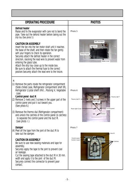
Defrost heater<br />
Raise and fix the evaporator with care not to bend the<br />
pipe. Take out the deforst heater before taking out the<br />
drip tray (See photo 5.)<br />
CAUTION ON ASSEMBLY<br />
Insert the fan into the fan motor shaft until it reaches<br />
the base of the shaft, and then rotate the fan gently<br />
with your fingers to check its operation.<br />
Securely attach the defrost heater in the correct<br />
direction, slacking the lead wire to prevent water from<br />
entering the glass tube.<br />
Attach the drip tray close up to the inside box.<br />
Be sure to attach the thermal fuse to the correct<br />
position.Securely attach the lead wire to the fixture.<br />
2.<br />
(1) Remove the parts inside the refrigerator compartment<br />
(Slide chilled case, Refrigerator compartment shelf (R),<br />
Refrigerator Crystal shelff (RV) , Packing V, Vegetable<br />
case.<br />
Control penel duct R<br />
(2) Remove 2 rivets and 3 screws in the upper part of the<br />
control panel and pull it out toward you.<br />
(See photo 6.)<br />
(3) Remove the thermo dial (Refrigerator compartment)<br />
and unlock the catches of the control panel (6 catches)<br />
to separate the control panel and the duct R.<br />
(See photo 7.)<br />
Damper<br />
(4) Peel off the tape from the joint of the duct R to<br />
take out the damper.<br />
CAUTION ON ASSEMBLY<br />
Be sure to use new sealing materials and tape for<br />
assembly.<br />
Securely apply the tape to the joint to prevent cool<br />
air leakage.<br />
Cut the sealing tape attached to the duct R in 30 mm.<br />
width and apply it to the joint of the duct R.<br />
Securely connect the connector to prevent poor<br />
contact.<br />
- 9 -<br />
Photo 5<br />
Photo 6<br />
Thermo dial R<br />
Room light Cover<br />
Photo 7<br />
Control panel<br />
Control board<br />
Defrost heater<br />
Evaporator<br />
DEF thermistor<br />
Heater cover<br />
Rivets Thermo dial F<br />
Room light<br />
Screws<br />
Control panel<br />
Duct R<br />
Catches