SERVICE MANUAL MR-G57N-T-NZ - B.d.t.
SERVICE MANUAL MR-G57N-T-NZ - B.d.t.
SERVICE MANUAL MR-G57N-T-NZ - B.d.t.

Create successful ePaper yourself
Turn your PDF publications into a flip-book with our unique Google optimized e-Paper software.
HOME REFRIGERATOR<br />
<strong>SERVICE</strong> <strong>MANUAL</strong><br />
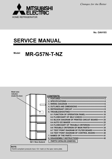
Model <strong>MR</strong>-<strong>G57N</strong>-T-<strong>NZ</strong><br />
Model name<br />
indication<br />
(Inside this door)<br />
<strong>NZ</strong> ••• New Zealand<br />
NOTE:<br />
• RoHS compliant products have mark on the spec name plate.<br />
No. OAH103<br />
CONTENTS<br />
1. FEATURES ••••••••••••••••••••••••••••••••••••••••••••••••••••••••••••••••••3<br />
2. SPECIFICATIONS ••••••••••••••••••••••••••••••••••••••••••••••••••••••••••4<br />
3. WIRING DIAGRAM ••••••••••••••••••••••••••••••••••••••••••••••••••••••••6<br />
4. OUTLINES AND DIMENSIONS •••••••••••••••••••••••••••••••••••••••••8<br />
5. REFRIGERANT CIRCUIT ••••••••••••••••••••••••••••••••••••••••••••••••9<br />
6. TROUBLESHOOTING••••••••••••••••••••••••••••••••••••••••••••••••••• 10<br />
6-1 FUNCTION OF OPERATION PANEL ••••••••••••••••••••••••••• 10<br />
6-2 FLOWCHART OF SELF-CHECK •••••••••••••••••••••••••••••••• 21<br />
6-3 BLOCK DIAGRAM OF PRINTED CIRCUIT BOARD •••••••• 25<br />
6-4 AUTO ICE MAKER ••••••••••••••••••••••••••••••••••••••••••••••••• 25<br />
6-5 FLOWCHART OF TROUBLE CRITERION •••••••••••••••••••• 27<br />
6-6 TROUBLE CRITERION OF MAIN PARTS ••••••••••••••••••••• 34<br />
6-7 TEST POINT DIAGRAM OF FILTER BOARD •••••••••••••••• 39<br />
6-8 TEST POINT DIAGRAM OF CONTROL BOARD •••••••••••• 40<br />
7. NAMES OF THE PARTS ••••••••••••••••••••••••••••••••••••••••••••••• 41<br />
8. DISASSEMBLY INSTRUCTIONS ••••••••••••••••••••••••••••••••••••• 42<br />
PARTS CATALOG (OAB103)
1<br />
FEATURES<br />
<strong>MR</strong>-<strong>G57N</strong>-<strong>NZ</strong><br />
1. Vitamin-enhancing vegetable compartment<br />
This is a totally new-concept vegetable compartment, which enhances<br />
2<br />
the nutritional value of vegetables by irradiating LED light.<br />
2 wavelength 590nm<br />
Orange LED<br />
It encourages the<br />
vegetables to generate<br />
reducing sugar, which<br />
is the source of the<br />
1<br />
vegetable’s life, and<br />
increases vitamin C.<br />
1 This is a comparison value between the 25% drop on the 2002 conventional product of<br />
our company (<strong>MR</strong>-S46B) and the 10% increase on the 2008 new model. The sprouts<br />
were wrapped in plastic and put under LED. It was measured under the following<br />
condition: about 90 % humidity and a refrigerator temperature of about 5 ºC.<br />
The effect depends on the positional relation with other vegetables and LED light, and<br />
the amount of vegetables stored in the compartment.<br />
3<br />
Vitamin-enhancing<br />
vegetable compartment
2<br />
SPECIFICATIONS<br />
<strong>MR</strong>-<strong>G57N</strong>-<strong>NZ</strong><br />
Accessories<br />
Weight<br />
SPECIFICATIONS<br />
Power supply<br />
V,Hz<br />
Total capacity<br />
L<br />
Dimensions (H x W x D)<br />
mm<br />
Cabinet<br />
Food liner<br />
Cabinet<br />
Insulation<br />
Freezer door<br />
Refrigerator door<br />
Freezer<br />
Cooling system<br />
Refrigerator<br />
Evaporator<br />
Condenser<br />
Defrost system<br />
Drain<br />
Temperature control system<br />
Refrigerator compartment room light<br />
Unit<br />
Shipping<br />
Capillary tube<br />
Desiccant (molecular sieve)<br />
Refrigerant filling capacity R600a<br />
Refrigerating oil (Model)<br />
kg<br />
kg<br />
mm<br />
g<br />
g<br />
g<br />
230 V, 50 Hz<br />
613 (gross) 447 (storage)<br />
1821 x 745 x 728<br />
Acrylic resin coated steel<br />
ABS resin<br />
Foamed polyurethane (Cyclopentane)<br />
Foamed polyurethane (Cyclopentane)<br />
Foamed polyurethane (Cyclopentane)<br />
Forced air convection<br />
Forced air convection<br />
Fin and tube type<br />
Cabinet, sides, back and front flange<br />
Automatic heater defrost<br />
Automatic drainage, Forced evaporation method<br />
Automatic control<br />
240 V,10 W (E14)<br />
Free pocket (L)<br />
Free pocket (S)<br />
Bottle pocket (S)<br />
Bottle pocket (L)<br />
AUTO-shelf<br />
Two-way flexishelf<br />
Small item case<br />
Free egg shelf<br />
Slide chilled case<br />
Slide chilled case lid<br />
Versa case<br />
Aluminum tray (Versa case)<br />
Water tank (With light-type bacteria removing filter)<br />
Freezing case (upper)<br />
Freezing case (lower)<br />
Ice server<br />
Soundproof mat<br />
Ice storage bin<br />
Vegetable case<br />
Vegetable stand<br />
Sliding case (Vegetable case)<br />
Toe grille<br />
98<br />
108<br />
1.8 x 0.76 x 2820, 1.6 x 0.65 x 2820<br />
9<br />
72<br />
187 (FREOL S10)<br />
4<br />
2pcs.<br />
2pcs.<br />
1pc.<br />
1pc.<br />
2pcs.<br />
1pc.<br />
1pc.<br />
1pc.<br />
1pc.<br />
1pc.<br />
1pc.<br />
1pc.<br />
1pc.<br />
1pc.<br />
1pc.<br />
1pc.<br />
1pc.<br />
1pc.<br />
1pc.<br />
1pc.<br />
1pc.<br />
1pc.
ELECTRICAL PARTS SPECIFICATIONS<br />
<strong>MR</strong>-<strong>G57N</strong>-<strong>NZ</strong><br />
Defrosting<br />
control<br />
Fan motor<br />
Temperature control<br />
Model<br />
Dial position<br />
HI<br />
MID<br />
LOW<br />
REFRIGERATOR<br />
CHILLED<br />
LOW (Soft freezing)<br />
MID (Soft freezing)<br />
HI (Soft freezing)<br />
FREEZER<br />
ICE MAKING<br />
ICE MAKING STOP<br />
CRYSTAL ICE MAKING<br />
Model<br />
Power supply<br />
Compressor<br />
Rated input<br />
Starting current<br />
W<br />
A<br />
Running current A<br />
Winding resistance (A.T.20 )<br />
Model<br />
Motor protector<br />
Ambient temperature<br />
Time<br />
Sec.<br />
Current<br />
A<br />
Three-way valve<br />
Model<br />
Type<br />
Defrosting Model<br />
timer Specification<br />
Defrost finish<br />
Freezer Thermal fuse<br />
compartment Defrost heater<br />
Deodorizing function of defrost heater<br />
Model<br />
Type<br />
Refrigerator Input<br />
W<br />
Revolution<br />
Number of poles<br />
Model<br />
rpm<br />
Machine Input<br />
W<br />
Chamber Revolution<br />
Number of poles<br />
Water pipe heater<br />
rpm<br />
Heater<br />
(Rating)<br />
Rotational heater board<br />
Vegetable compartment heater 1<br />
Vegetable compartment heater 2<br />
Ice making tray heater<br />
Ice maker temperature<br />
Freezer Refrigerator<br />
NTC thermistor<br />
Versa Ice making Vegetable<br />
Compressor Motor damper<br />
Heater<br />
ON<br />
-23.8<br />
-21.1<br />
-18.4<br />
–<br />
–<br />
–<br />
–<br />
–<br />
–<br />
–<br />
–<br />
–<br />
OFF<br />
-25.4<br />
-22.7<br />
-20.0<br />
–<br />
–<br />
–<br />
–<br />
–<br />
–<br />
–<br />
–<br />
–<br />
OPEN<br />
1.9<br />
5.1<br />
8.4<br />
–<br />
1.3<br />
–<br />
–<br />
–<br />
–<br />
–<br />
–<br />
–<br />
5<br />
EFI100E 13DAH<br />
230 V, 50Hz<br />
45/159 (1620/4800rpm)<br />
2.0 (Current limiter)<br />
0.63/2.19 (1620/4800rpm)<br />
9.27<br />
MM3-71CCV<br />
25<br />
16 or less<br />
17.0<br />
NSCE001DC1<br />
4-phase stepping motor drive voltage DC12V<br />
SHUT<br />
0.7<br />
3.8<br />
7.0<br />
–<br />
0.1<br />
–<br />
–<br />
–<br />
–<br />
–<br />
–<br />
–<br />
OPEN<br />
–<br />
–<br />
–<br />
4.7<br />
1.5<br />
-1.6<br />
-4.3<br />
-6.2<br />
-14.5<br />
–<br />
–<br />
–<br />
Control board<br />
Microcomputer<br />
Thermistor 14 1.5<br />
70 ± 2<br />
325 (240V,177W)<br />
Not equipped<br />
UDQM002B3<br />
DC brushless motor<br />
2.4 (12V DC)<br />
1520 (12V DC)<br />
10P<br />
4715JL04WS16G51<br />
1.4 (12V DC)<br />
1450 (12V DC)<br />
4P<br />
240V-8.7W<br />
240V-8.7W<br />
240V-6.5W<br />
240V-13.2W<br />
240V-11.9W<br />
-11.6<br />
SHUT<br />
–<br />
–<br />
–<br />
3.4<br />
0.2<br />
-2.8<br />
-5.6<br />
-7.4<br />
-19<br />
–<br />
–<br />
–<br />
OPEN<br />
–<br />
–<br />
–<br />
–<br />
–<br />
–<br />
–<br />
–<br />
–<br />
-17.9<br />
-17.9<br />
-17.9<br />
SHUT<br />
–<br />
–<br />
–<br />
–<br />
–<br />
–<br />
–<br />
–<br />
–<br />
-21.9<br />
-21.9<br />
-21.9<br />
ON<br />
0.4<br />
1.9<br />
3.5<br />
–<br />
–<br />
–<br />
–<br />
–<br />
–<br />
–<br />
–<br />
–<br />
OFF<br />
-0.9<br />
0.7<br />
2.3<br />
–<br />
–<br />
–<br />
–<br />
–<br />
–<br />
–<br />
–<br />
–
3<br />
<strong>MR</strong>-<strong>G57N</strong>-<strong>NZ</strong><br />
WIRING DIAGRAM<br />
I.THERMISTOR (Ice making compartment thermistor)<br />
V.THERMISTOR (Vegetable compartment thermistor)<br />
VERSA.THERMISTOR (Versa compartment thermistor)<br />
DEF.THERMISTOR (Defrost thermistor)<br />
ICE-TRAY THERMISTOR (Ice making tray thermistor)<br />
F.THERMISTOR (Freezer compartment thermistor)<br />
R.THERMISTOR (Refrigerator compartment thermistor)<br />
( SKELETON WIRING DIAGRAM )<br />
6<br />
RESISTOR<br />
ASSY
<strong>MR</strong>-<strong>G57N</strong>-<strong>NZ</strong><br />
Freezer<br />
Compartment Door<br />
Freezer<br />
Compartment<br />
Thermal fuse<br />
F. Thermistor<br />
Defrost heater<br />
Freezer room<br />
Door switch<br />
Vegetable<br />
Compartment Door<br />
Vegetable<br />
Compartment<br />
V. heater 1<br />
Compressor<br />
Valve motor<br />
Fan motor<br />
(Freezer)<br />
Vegetable LED<br />
Motor<br />
protector<br />
Ice tray<br />
heater<br />
V. Thermistor<br />
Ice/ Versa Compartment Door<br />
Motor<br />
damper<br />
I.THERMISTOR (Ice making compartment thermistor)<br />
V.THERMISTOR (Vegetable compartment thermistor)<br />
VERSA.THERMISTOR (Versa compartment thermistor)<br />
DEF.THERMISTOR (Defrost thermistor)<br />
ICE-TRAY THERMISTOR (Ice making tray thermistor)<br />
F.THERMISTOR (Freezer compartment thermistor)<br />
R.THERMISTOR (Refrigerator compartment thermistor)<br />
Fan motor<br />
(Compressor)<br />
Ice tray<br />
thermistor<br />
I. Thermistor<br />
Ice<br />
gear box<br />
S. thermistor<br />
DEF. Thermistor<br />
Versa<br />
Compartment<br />
Water pipe heater<br />
Water pump<br />
motor<br />
( ACTUAL WIRING DIAGRAM )<br />
Refrigerator/<br />
Ice room Door<br />
switch<br />
Ice<br />
Compartment<br />
Motor<br />
damper<br />
( When the doors are closed. )<br />
7<br />
Refrigerant Compartment Door<br />
R. Thermistor<br />
Room light<br />
under side<br />
Refrigerant<br />
Compartment<br />
Room light<br />
upside<br />
Electric<br />
box<br />
N/F board<br />
TEMP.<br />
CONTROL BOARD<br />
Divider Heater (R)<br />
RESISTOR<br />
ASSY
4<br />
<strong>MR</strong>-<strong>G57N</strong>-<strong>NZ</strong><br />
86<br />
203<br />
196<br />
OUTLINES AND DIMENSIONS<br />
312.5<br />
310<br />
312.5<br />
318<br />
249<br />
400<br />
244<br />
655<br />
641<br />
655<br />
655<br />
607<br />
601<br />
601<br />
599<br />
376<br />
351<br />
415<br />
374<br />
367<br />
77<br />
337<br />
440<br />
396<br />
1821(Display)<br />
8<br />
8<br />
361<br />
361<br />
283.5<br />
283.5<br />
DOOR DIMENSION<br />
L(R) R(R) I S V F<br />
Hight 822 822 214 214 361 361<br />
Width 283.5 349.5 283.5 454.5 744 744<br />
104<br />
745(Display)<br />
740(Cabinet)<br />
454.5<br />
638(Pitch between the rear wheels)<br />
691(Pitch between the adjust bolts)<br />
726(Pitch between the front wheels)<br />
6<br />
6<br />
454.5<br />
362 214 822<br />
362<br />
12<br />
7<br />
7<br />
7<br />
760<br />
53<br />
41<br />
331 175<br />
39<br />
325<br />
100<br />
1821<br />
75<br />
728(Display)<br />
596<br />
655<br />
R(L) : Refrigerator compartment (Left)<br />
R(R) : Refrigerator compartment (Right)<br />
I : Ice making compartment<br />
S : Select compartment [Versa compartment]<br />
V : Vegetable compartment<br />
F : Freezer compartment<br />
8<br />
10<br />
309<br />
728<br />
142<br />
181 101<br />
290<br />
96<br />
2500<br />
633 10<br />
255<br />
195 1522<br />
REQUIRED SPACE FOR INSTALLATION<br />
37<br />
20 745 20<br />
950<br />
211<br />
165.5<br />
125<br />
125.5<br />
173<br />
~<br />
~<br />
~<br />
~<br />
206.5<br />
83.5<br />
84.5<br />
214<br />
333.5<br />
Unit : mm<br />
1121
5<br />
<strong>MR</strong>-<strong>G57N</strong>-<strong>NZ</strong><br />
REFRIGERANT CIRCUIT<br />
Drain pan<br />
Compressor<br />
9<br />
Dryer<br />
#150<br />
Charge pipe<br />
(Low pressure<br />
side) 6.35<br />
Condenser<br />
Charge pipe<br />
(High pressure side)<br />
4.0<br />
Muffler<br />
Evaporator<br />
Cabinet pipe<br />
Three-way<br />
valve<br />
Suction pipe<br />
Capillary tube<br />
1.8× 0.76×2820(mm)<br />
Capillary tube<br />
1.6× 0.65×2820(mm)
6<br />
TROUBLESHOOTING<br />
6-1 FUNCTION OF OPERATION PANEL<br />
<strong>MR</strong>-<strong>G57N</strong>-<strong>NZ</strong><br />
(1) Function of normal operation<br />
ROOM button<br />
Pressing this button selects the<br />
compartment to be displayed.<br />
Press to select the<br />
compartment before adjusting<br />
the temperature or cooling fast.<br />
SELECTION / QUICK button<br />
Pressing this button sets each compartment’s<br />
temperature.<br />
In order to cool fast,<br />
Press for 3 seconds.<br />
When the versa compartment is set at soft freezing<br />
mode, fast cooling cannot be selected.<br />
QUICK mode stops automatically<br />
• QUICK mode automatically stops in 2 hours.<br />
1<br />
When stopping QUICK mode before it automatically ends<br />
• Press .<br />
USEFUL FUNCTIONS<br />
Child Lock<br />
Press and simultaneously for 3 seconds.<br />
Stop ice making<br />
2 Press several times until is displayed.<br />
Operating mode and Temperature range<br />
Compartment Mode Temp. range<br />
Refrigerator<br />
compartment<br />
Versa<br />
compartment<br />
Ice making<br />
compartment<br />
Vegetable compartment<br />
Freezer compartment<br />
Middle<br />
Chilled<br />
Refrigerator<br />
Chilled<br />
Soft freezing (Middle)<br />
Freezer<br />
Normally<br />
Ice making stop<br />
Clear<br />
Middle<br />
Middle<br />
ECO MODE button<br />
Each compartment can be operated<br />
with energy saved.<br />
Approx. 0 to 6 °C<br />
Approx. -2 to 2 °C<br />
Approx. 0 to 6 °C<br />
Approx. -2 to 2 °C<br />
Approx. -9 to -5 °C<br />
Approx. -18 to -16 °C<br />
Approx. -21 to -17 °C<br />
Approx. -21 to -17 °C<br />
Approx. -21 to -17 °C<br />
Approx. 3 to 9 °C<br />
Approx. -21 to -17 °C<br />
The temp. range is based on the data measured at the center of each compartment<br />
with the door closed and with no food inside under the condition of ambient temperature 30 °C.<br />
10<br />
ICE SELECT button<br />
Pressing this button selects the setting<br />
of the ice making compartment.<br />
To reset the unit to the initial setting, press for 3 seconds.<br />
The refrigerator compartment, vegetable compartment, and the<br />
freezer compartment will be set to "Middle", and fast cooling<br />
operation for all compartments will be canceled.<br />
·The display extinguishes in 30 seconds<br />
after the last button is pressed.<br />
(No failure in refrigerator)<br />
·Pushing any button turns on the display<br />
again.
(2) Demonstration mode for shop display<br />
Setting<br />
Within 1 minute after power supply turns on, press the , , and simultaneously for 5 seconds<br />
with the door of the ice making compartment opened.<br />
When the setting is complete, a “beep” sound is heard and “Auto Demo Mode” is displayed.<br />
Demonstration mode is not available when the temperature of freezer compartment is –7 °C or lower.<br />
Panel operation mode during demonstration mode<br />
The panel operation mode changes to “manual” if any of the switches is pressed. It changes to "auto" if none of the switches<br />
is pressed for 45 seconds since the last time any of the switches was pressed.<br />
Manual mode: Panel indication changes according to switch operation.<br />
Auto mode: Panel indication is automatically changed.<br />
Release<br />
Simultaneously press , , and switch for about 5 seconds with the door of ice making compartment<br />
left open.<br />
When the function is released, a “beep” sound is heard.<br />
Note: Follow the procedure above to release demonstration mode as it cannot be released by simply turning<br />
on/off the power supply.<br />
(3) Fine adjustment of temperature<br />
Fine adjustment of temperature is available for refrigerator compartment, freezer compartment and versa<br />
compartment.<br />
As for versa compartment, however, it is only available when the compartment is set to or .<br />
Setting<br />
Simultaneously press , ,for about 3 seconds until a “beep” sound is heard.<br />
Room display blinks every 10 seconds in fine adjustment mode.<br />
Fine adjustments of temperature<br />
Follow the same operation procedure for temperature adjustment.<br />
Fine adjustment of temperature<br />
Normal mode Fine adjustment mode<br />
L L<br />
L M<br />
L H<br />
L M L M<br />
L M<br />
M M<br />
M H<br />
M H M H<br />
L H<br />
M H<br />
H H<br />
Release<br />
Follow the same procedure as setting and the finely-adjusted temperatures are reset for refrigerator compartment, freezer<br />
compartment and versa compartment at once.<br />
Temperature is adjusted by approximately 0.3 ~ 0.6 °C.<br />
(4) Ice making test / Self-check<br />
This function is not available during the following modes: Child lock, Demonstration, Cooking timer, Changing the<br />
rotational speed of compressor, and Error code display.<br />
Setting<br />
Press for about 5 seconds.<br />
Operation and its display<br />
While automatic ice making is testing, the indication of ice making compartment setting blinks on display.<br />
When something is faulty, the error code is indicated.<br />
Release<br />
The test automatically finishes in 10 minutes and the error code changes to temperature display.<br />
11<br />
Note: -25 °C freezing.<br />
Select the maximum setting of the<br />
temperature adjustment function for the<br />
freezer compartment.<br />
There is no particular display when the<br />
setting is selected.
(5) Service Check Function<br />
1) Outline<br />
•The chart below shows the outline of service check function.<br />
•“Service check entry” needs to be set in order to perform each check mode. After setting “service check entry,” start the<br />
setting operation of the check mode to be displayed.<br />
• blinks while performing service check function.<br />
•The display of indicates which mode is in operation.<br />
•When one of the check modes is in operation, other modes cannot be set. The mode in operation needs to be canceled<br />
before setting another mode.<br />
Once each check mode starts, it continues operating even if the door gets closed.<br />
(Open the door when releasing each mode.)<br />
Refer to the next sections about the operation procedure and display of each check mode.<br />
•In order to release “service check function entry,” follow the same procedure as setting operation during “service check<br />
function entry” or each check mode.<br />
Service check function entry<br />
Mode<br />
1) Compressor’s rotational speed change mode<br />
…The rotational speed of the compressor can be<br />
changed; The fan motor in machine chamber<br />
can be switched on and off.<br />
2) Damper Operation mode<br />
…Each damper can be opened and closed; Refrigerator<br />
fan can be switched on/off.<br />
3) Thermistor temperature check mode<br />
…The detected temperature of each thermistor can<br />
be checked.<br />
4) Error history display mode<br />
…The error occurred in the past can be checked.<br />
(1) History display mode<br />
…All the error occurred in the past can be<br />
checked in numeric order.<br />
(2) Order of occurrence mode<br />
…The newest 5 errors (at the maximum) are<br />
displayed form the newest to the older.<br />
5) Set temperature adjustment mode<br />
…Set temperature in each compartment can be<br />
adjusted.<br />
Setting / releasing method Display<br />
Door Button operation Blinking<br />
Open the<br />
ice making compartment’s<br />
door<br />
Leave the<br />
ice making<br />
compartment’s<br />
door open<br />
Leave the<br />
ice making<br />
compartment’s<br />
door open<br />
Leave the<br />
ice making<br />
compartment’s<br />
door open<br />
Leave the<br />
ice making<br />
compartment’s<br />
door open<br />
Leave the<br />
ice making<br />
compartment’s<br />
door open<br />
12<br />
Simultaneously press<br />
and for 3 seconds<br />
Setting method<br />
Display<br />
Door Button operation Lighting Blinking<br />
-<br />
-<br />
Press<br />
for 3 seconds<br />
Simultaneously press<br />
and<br />
for 3 seconds<br />
Press<br />
for 3 seconds<br />
Simultaneously press<br />
and<br />
for 3 seconds<br />
Press<br />
Press<br />
FZR<br />
“History display mode” and “Order of occurrence mode” are<br />
switched over each time is pressed.<br />
(1)<br />
VEG<br />
(2)<br />
Simultaneously press<br />
and<br />
for 3 seconds<br />
(1)<br />
(2)<br />
(3)<br />
(4)<br />
(4)<br />
(4)<br />
(5)
2) Compressor’s rotational speed change mode<br />
Setting<br />
With the ice making compartment’s door opened, simultaneously press and for 3 seconds until a “beep”<br />
sound is heard. starts to blink.<br />
With the door opened, press for 3 seconds to start compressor’s rotational speed change mode.<br />
Once this mode starts, it continues operating even if the door gets opened.<br />
Compressor’s rotational speed change mode is not available during demonstration mode, thermistor temperature mode,<br />
temperature adjustment mode, error history mode, or when child lock is effective.<br />
Display during compressor’s rotational speed change mode<br />
During compressor’s rotational speed change mode, blinks and lights up.<br />
Display of rotational speed<br />
• Compressor’s rotational speed is divided into ones’ place and tens’ place when it is displayed.<br />
• One of the values (8/4/2/1) is assigned to each indicator of both tens’ place and one’ place on the display panel. The sum of<br />
the corresponding values of the lighting indicators is the compressor’s rotational speed.<br />
Compressor’ s<br />
rotational speed<br />
Tens’ place<br />
…<br />
Temperature<br />
Adjustment Display<br />
Lighting<br />
Corresponding<br />
values<br />
REF CHIL 8 4<br />
SOFT FZR 2 1<br />
e.g.) Compressor’s rotational speed 56rps, Fan in machine chamber OFF<br />
Tens’ place "5"<br />
(=4+1)<br />
13<br />
Display during<br />
Compressor’ s<br />
rotational speed change mode<br />
Fan in machine<br />
chamber<br />
ON/OFF<br />
Ice Making Mode<br />
Display<br />
Compressor’ s<br />
rotational speed<br />
Ones’ place<br />
…<br />
Blinking<br />
Corresponding<br />
values<br />
REG QCK 8 4<br />
CRL STOP 2 1<br />
Fan in machine<br />
chamber OFF<br />
Ones’ place "6"<br />
(=4+2)<br />
Changing the rotational speed<br />
After setting this mode, compressor’s rotational speed changes every time button is pressed.<br />
Rotational speed (rps) is divided into ones’ place and tens’ place when it is displayed.<br />
(Basically the compressor starts operation at level 10, however, it may be different depending on models, or as a result of<br />
specification change.<br />
<br />
Normal<br />
Level 0 Level 1 Level 2 Level 3 Level 4 Level 5<br />
Low speed<br />
Rotational speed can be changed only when the compressor is in operation. While the compressor stops, rotational speed is<br />
not displayed, and button operation is not effective. When the compressor stops, unplug the power code, and wait for<br />
a few minutes, then plug it again.<br />
Operation sound may get increase in the process of changing rotational speed, but that is not dysfunction. Check the sound<br />
level when rotational speed is stabilized.<br />
Switching ON/OFF the machine chamber fan motor<br />
In this mode, fan motor in machine chamber can be switched on and off at each press of .<br />
Release<br />
The ON/OFF state is displayed with<br />
on the display panel.<br />
Machine chamber fan motor Display of ECO<br />
ON<br />
Lighting<br />
OFF<br />
Not lighting<br />
Level 6 Level 7 Level 8 Level 9 Level 10<br />
High speed<br />
With the ice making compartment’s door opened, press and simultaneously for 3 seconds until a “beep”<br />
sound is heard. The screen returns to the normal temperature display.<br />
The function is automatically released in one hour.<br />
Although unplugging and plugging the power code can release this function, it is recommended to follow the procedure<br />
above for protection of the compressor.
3) Damper Operation Mode<br />
Setting<br />
With the ice compartment door opened, press<br />
heard. blinks.<br />
and simultaneously for 3 seconds until a “beep” sound is<br />
With the door opened, press and simultaneously for 3 seconds until a “beep” sound is heard.<br />
Damper operation mode starts. Once this mode starts, it continues operating even if the door gets closed.<br />
Damper operation mode is not available during demonstration mode, thermistor temperature mode, compressor’s rotational<br />
speed change mode, temperature adjustment mode, error history mode, or when child lock is effective.<br />
Display during damper operation mode<br />
During damper operation mode, blinks and lights up.<br />
Control state display of each damper<br />
a)Damper<br />
serial number<br />
Light<br />
b)State of damper<br />
upper: the damper<br />
lower: the next damper<br />
(Operating: Blinks)<br />
During<br />
damper<br />
operation<br />
c)Refrigerator<br />
fan ON/OFF<br />
14<br />
Blinks<br />
d)Display during damper<br />
operation “Blinks”<br />
a) Damper serial number<br />
The room display on the display panel corresponds to the values representing damper types. The room display indicators<br />
and their corresponding values (8/4/2/1) are shown the tables below.<br />
Each serial number is assigned to each compartment (thermistor), which is used in thermistor temperature mode and<br />
set temperature adjustment mode besides damper operation mode. The sum of the corresponding values of the lighting<br />
indicators is the damper’s serial number.<br />
Room Display Corresponding values<br />
REF VR 8 4<br />
VEG FZR 2 1<br />
Serial number Assigned compartment Damper operation mode<br />
1 Refrigerator compartment<br />
2 Slide chilled compartment<br />
3 Ice making compartment<br />
4 Versa compartment<br />
5 Vegetable compartment<br />
6 Freezer compartment<br />
7 Defrosting<br />
8 Ice tray<br />
9 Outdoor air<br />
10 Deodorization<br />
/ : SW operation is effective / ineffective<br />
b) State of damper<br />
REF and CHIL displayed on the upper part indicate the present state of the damper, and SOFT and FZR displayed on the<br />
lower part indicate the state of the next damper operation.<br />
REF and SOFT displayed on the left side indicate that the damper is open, and CHIL and FZR displayed on the right side<br />
indicate that the damper is close.<br />
Present<br />
Next<br />
REF CHIL<br />
SOFT FZR<br />
Open Close<br />
c) ON/OFF state of refrigerator fan motor<br />
ECO indicates the ON/OFF state of refrigerator fan motor.
Opening and closing dampers<br />
(1) Press to select the damper to be set. Each press of the button makes a “beep” sound and changes the kind of<br />
dampers. The serial number described in a) indicates the selected damper.<br />
The selected damper is displayed using the serial number (1: refrigerator ~ 10: deodorization) in numeric order repeatedly.<br />
Refrigerator damper slide chilled compartment damper ice making compartment damper outdoor air deodorization damper<br />
Slide chilled compartment, vegetable compartment, defrosting, ice tray, outdoor air, and deodorization can be selected;<br />
however, it is ineffective in damper operation mode.<br />
Status display of damper<br />
1. REF and SOFT displayed on the left side indicate that the damper is open, and CHIL and FZR displayed on the right side<br />
indicate that the damper is close.<br />
2. REF and CHIL displayed on the upper part indicate the present state of the damper, and SOFT and FZR displayed on the<br />
lower part indicate the state of the next damper operation.<br />
3. The selected status (open or close) of both present and next damper states lights up when the selected damper is operational.<br />
However, FZR keeps lighting up as the next state when the selected damper is not operational.<br />
Present<br />
Next<br />
REF CHIL<br />
SOFT FZR<br />
Open<br />
Close<br />
4. When the selected damper is in operation, the indicator for the present state blinks.<br />
5. When any of the dampers, including the one that is not selected, is in operation, "d) display during damper operation" blinks.<br />
(2) Press , and then select "SOFT" to open the damper or "FZR" to close the damper.<br />
(3) Press for 3 seconds to operate the damper. (A “beep” sound is heard when the setting has been conveyed.)<br />
Setting of the operating damper cannot be changed.<br />
Damper operation stops automatically. (Blinking changes to lighting.)<br />
e.g.) When changing the damper of ice making compartment from “CLOSE” state to “OPEN” state, select the indicators as<br />
shown below and press for 3 seconds.<br />
Switching ON/OFF the refrigerator fan motor in the unit<br />
In this mode, each press of switches on and off the refrigerator fan motor.<br />
The ON/OFF state of the refrigerator fan motor is represented with .<br />
"ECO" display Fan motor in the unit<br />
Lighting ON<br />
Not lighting OFF<br />
Release<br />
a)Serial b)State of damper<br />
number Present “CHIL” : Close<br />
“3” : Ice making Next “SOFT” : Open<br />
compartment<br />
With the ice making compartment’s door opened, press and simultaneously for 3 seconds until a “beep” sound is<br />
heard. The screen returns to the normal temperature display.<br />
The function is automatically released in one hour.<br />
Although unplugging and plugging the power code can release this function, it is recommended to follow the procedure<br />
above for protection of the compressor.<br />
15<br />
c)Refrigerator fan<br />
Lighting : ON<br />
d)
4) Thermistor temperature check mode<br />
Setting<br />
With the ice compartment door opened, press and simultaneously for 3 seconds until a “beep” sound is<br />
heard. blinks.<br />
With the door opened, press for 3 seconds.<br />
Thermistor temperature check mode starts. Once this mode starts, it continues operating even if the door gets closed.<br />
Thermistor temperature check mode is not available during demonstration mode, Compressor's rotational speed change<br />
mode, set temperature adjustment mode, error history display mode, or when child lock is effective.<br />
Display during thermistor temperature check mode<br />
During thermistor temperature check mode, blinks and lights up.<br />
Displaying the thermistor temperature<br />
The kind and temperature of thermistor is displayed on the operation panel.<br />
Outside temperature detected by thermistor may be a little different from the actual one due to the influence of the<br />
temperature in the refrigerator.<br />
a)Thermistor<br />
Serial number<br />
b)Thermistor<br />
temperature<br />
tens’ place<br />
a) Thermistor serial number<br />
The room display on the display panel corresponds to the values representing thermistor types. The room display indicators<br />
and their corresponding values (8/4/2/1) are shown the tables below.<br />
Each serial number is assigned to each compartment (thermistor), which is used in damper operation mode and<br />
set temperature adjustment mode besides thermistor temperature mode. The sum of the corresponding values of the<br />
lighting indicators is the thermistor’s serial number.<br />
Room Display Corresponding values<br />
REF VR 8 4<br />
VEG FZR 2 1<br />
Light<br />
c)Thermistor<br />
temperature<br />
± signs<br />
Display during<br />
thermistor temperature<br />
check mode<br />
Serial number Assigned compartment Thermistor temperature check mode<br />
1 Refrigerator compartment<br />
2 Slide chilled compartment<br />
3 Ice making compartment<br />
4 Versa compartment<br />
5 Vegetable compartment<br />
6 Freezer compartment<br />
7 Defrosting<br />
8 Ice tray<br />
9 Outdoor air<br />
10 Deodorization<br />
/ : SW operation is effective / ineffective<br />
b) Thermistor temperature tens’ place<br />
Tens’ place of thermistor temperature is indicated on the display part which is usually used for temperature adjustment of<br />
slide chilled compartment.<br />
Display of REF / CHIL / SOFT / FZR corresponds to the values, 8/4/2/1. The sum of the corresponding values of the blinking<br />
indicators is the tens’ place of thermistor temperature.<br />
Temperature Adjustment Display Corresponding values<br />
REF CHIL 8 4<br />
No indicator lights up when it is “0”.<br />
SOFT FZR 2 1<br />
c) Thermistor temperature signs<br />
Plus and minus signs of thermistor temperature are indicated on the display which is usually used for "ECO" mode.<br />
ECO Thermistor temperature signs<br />
Lighting -<br />
Not lighting +<br />
16<br />
d)Thermistor<br />
temperature<br />
ones’ place<br />
Blink
d) Thermistor temperature ones’ place<br />
Ones’ place of thermistor temperature is indicated on the display part which is usually used for ice making setting.<br />
Display of REG / QCK / CRL / STOP corresponds to the values, 8/4/2/1. The sum of the corresponding values of lighting<br />
indicators is the ones’ place of thermistor temperature.<br />
Ice making setting display Corresponding values<br />
REG QCK 8 4 No indicator lights up when it is “0”.<br />
CRL STOP 2 1<br />
e.g.) When freezer compartment thermistor is –25 ºC.<br />
a)Serial<br />
number<br />
“6” : Freezer<br />
Changing the thermistor on display<br />
b)Tens’ place<br />
“2”<br />
c)Sign<br />
“-”<br />
d)Ones’ place<br />
“5” (=4+1)<br />
While thermistor temperature is on display, press .<br />
Each press of the button makes a “beep” sound and changes the kind of thermistor.<br />
Each thermistor is displayed using the serial numbers described in a) in numeric order repeatedly (1: refrigerator<br />
compartment ~ 10: deodorization).<br />
Refrigerator compartment slide chilled compartment ice making compartment versa compartment vegetable<br />
compartment freezer compartment defrosting ice tray outdoor air deodorization damper<br />
When this mode is set, the display always starts from the refrigerator thermistor.<br />
Slide chilled compartment thermistor can be selected; however, it is ineffective because slide chilled compartment thermistor<br />
is not installed.<br />
Deodorization can be selected; however, it is ineffective in thermistor temperature check mode.<br />
Release<br />
With the ice making compartment’s door opened, press and simultaneously for 3 seconds until a “beep”<br />
sound is heard. The screen returns to the normal temperature display.<br />
The function is automatically released in one hour.<br />
Although unplugging and plugging the power code can release this function, it is recommended to follow the procedure<br />
above for protection of the compressor.<br />
5) Error history display mode<br />
The errors occurred in the past can be observed as an error history. Use this mode when the actual problem of<br />
the refrigerator is different from the error that was displayed at the service-call received.<br />
Error history display mode offers two ways of display. One of the two is “history display mode,” which shows all<br />
errors occurred in the past in numeric order of the error code; the other is “order of occurrence mode,” which<br />
shows the newest 5 errors (at the maximum) from the newest to the older.<br />
Error history display mode starts with “history display mode.”<br />
Setting<br />
With the ice compartment’s door opened, press and simultaneously for 3 seconds until a “beep” sound is<br />
heard. blinks.<br />
With the door opened, press and simultaneously for 3 seconds until a “beep” sound is heard.<br />
History error mode starts. Once this mode starts, it continues operating even if a door gets opened.<br />
Display during error history display mode<br />
During error history display mode, blinks and lights up.<br />
Display of error history information.<br />
Light<br />
a)Mode display b)Error code<br />
“History display Tens’ place<br />
mode” or<br />
“Order of occurrence<br />
mode”<br />
Display during error<br />
history display mode<br />
c)Error code<br />
Ones’ place<br />
a) Mode display<br />
Display the selected mode between “history display mode” and “order of occurrence mode.”<br />
b) Error code tens’ place<br />
It displays the tens’ place of error code.<br />
It applies the same representative method as the errorl display of self-check.<br />
c) Error code ones’ place<br />
It displays the tens’ place of error code.<br />
It applies the same representative method as the error display of self-check.<br />
17<br />
Blink
Switching over the mode<br />
Press to select one of the error history display modes. Each press of the button makes a “beep” sound and<br />
switches over between “history display mode” and “order of occurrence mode.”<br />
Compartment Error history display mode<br />
FZR History display mode Display all errors occurred in the past in numeric order of the error code<br />
VEG Order of occurrence mode Display the newest 5 errors (at the maximum) from the newest to the older.<br />
Display method<br />
Display method of the error code is the same as self check error display. (Refer to 6-2(3)); however, all indicators used for<br />
the display of error code light up simultaneously for 3 seconds before the first error code is displayed (“pre- display”).<br />
e.g.) When errors occurred in the following order:<br />
fan motor error (E31) communication error of operation panel (E01) refrigerator thermistor error (E13)<br />
•Display during history display mode<br />
Errors are displayed in numeric order.<br />
Tens’ place<br />
Ones’ place<br />
Error code Pre-display<br />
3sec.<br />
0.5<br />
sec.<br />
•Display during order of occurrence mode<br />
Errors are displayed from the newest to the older.<br />
Tens’ place<br />
Ones’ place<br />
E01 E13 E31<br />
0.5<br />
sec.<br />
Repetition<br />
When no error occurred in the past, error code is not displayed.<br />
Check points and resetting the error history<br />
Check and take appropriate measures according to the procedures as stated in 6-2(1).<br />
Conduct self-check to confirm there is no dysfunction. (Make sure all connectors are connected properly and there are<br />
no loose connection.)<br />
Refer to “ Setting” above and activate the error history mode again. With the ice making compartment’s door<br />
opened, press for 3 seconds to reset error history. (Resetting the error history is completed.) If it is completed<br />
correctly, no error code would be displayed.<br />
Release<br />
With the ice making compartment’s door opened, press and simultaneously for 3 seconds until a “beep”<br />
sound is heard. The screen returns to the normal temperature display.<br />
The function is automatically released in one hour.<br />
Although unplugging and plugging the power code can release this function, it is recommended to follow the procedure<br />
above for protection of the compressor.<br />
18<br />
0.5<br />
sec.<br />
5sec. 5sec. 5sec.<br />
Error code Pre-display E13 E01 E31<br />
3sec.<br />
0.5<br />
sec.<br />
0.5<br />
sec.<br />
Repetition<br />
0.5<br />
sec.<br />
0.5<br />
sec.<br />
0.5<br />
sec.<br />
Pre-display<br />
3sec.<br />
Pre-display<br />
5sec. 5sec. 5sec. 3sec.
6) Set temperature adjustment mode<br />
Switch operation on the operation panel changes the set temperature in each compartment.<br />
Setting<br />
With the ice compartment door opened, press<br />
blinks.<br />
and simultaneously for 3 seconds until a “beep” sound is heard.<br />
With the door opened, press and simultaneously for 3 seconds until a “beep” sound is heard.<br />
Set temperature adjustment mode starts. Once this mode starts, it continues operating even if the door gets closed.<br />
Display during set temperature adjustment mode<br />
During set temperature adjustment mode, blinks and lights up.<br />
Control state display of each compartment<br />
a)Compartment<br />
serial number<br />
Light<br />
b)Set temperature adjustment level<br />
a) Compartment serial number<br />
Serial number of the selected compartment for set temperature adjustment is displayed on the part that<br />
are usually used for room display.<br />
Each serial number is assigned to each compartment that will be used in set temperature adjustment mode besides damper<br />
operation mode and thermistor temperature check mode.<br />
The sum of the corresponding values of the lighting indicators is the compartment serial number.<br />
Room display Corresponding values<br />
REF VR 8 4<br />
VEG FZR 2 1<br />
Serial number Assigned compartment Set temperature adjustment mode<br />
1 Refrigerator compartment<br />
2 Slide chilled compartment<br />
3 Ice making compartment<br />
4 Versa compartment<br />
5 Vegetable compartment<br />
6 Freezer compartment<br />
7 Defrosting<br />
8 Ice tray<br />
9 Outdoor air<br />
10 Deodorization<br />
/ : SW operation is effective / ineffective<br />
b) Set temperature adjustment level<br />
Adjustment level of the set temperature is displayed on the display part that is usually used for temperature adjustment.<br />
Adjusting the set temperature<br />
19<br />
Display during set<br />
temperature<br />
adjustment mode<br />
(1) Select the compartment with button.<br />
(2) Each press of the button makes a “beep” sound and changes the compartment to adjust the set temperature.<br />
Each compartment will be displayed using the serial numbers (1: refrigerator compartment~ 6: Freezer<br />
compartment) in numeric order repeatedly.<br />
Refrigerator compartment slide chilled compartment versa compartment ice making compartment<br />
vegetable compartment freezer compartment<br />
Set temperature adjustment operation of slide chilled compartment is possible; however, it is ineffective because slide chilled<br />
compartment thermistor is not installed.<br />
Blink
(3) Select the adjustment level of set temperature with .<br />
Each press of the button makes a “beep” sound and changes the adjustment level of set temperature.<br />
There are 5 adjustment levels of set temperature ( 2 & 0), and the selected level is displayed.<br />
Adjustment level<br />
+2<br />
+1<br />
Temperature<br />
adjustment display<br />
REF<br />
CHIL<br />
Change of the set<br />
temperature<br />
About +2 ºC<br />
About +1 ºC<br />
±0 No change<br />
-1 About -1 ºC<br />
SOFT<br />
-2 About -2 ºC<br />
FZR<br />
Release<br />
With the ice making compartment’s door opened, press and simultaneously for 3 seconds until a “beep”<br />
sound is heard. The screen returns to the normal temperature display.<br />
The function is automatically released in one hour.<br />
Although unplugging and plugging the power code can release this function, it is recommended to follow the procedure<br />
above for protection of the compressor.<br />
Door Buzzer System :<br />
Door buzzer has been installed so that one will not forget to close the door.<br />
•The buzzer rings in the following conditions:<br />
1. When door is left open.<br />
2. When refrigerator fan motor or machine chamber fan motor is abnormal.<br />
3. When there is possibility that the door of freezer compartment is not closed securely.<br />
1. When door is left open<br />
Every 1 minute, for 4 minutes<br />
After 5 minutes<br />
Buzzer<br />
"Beep beep" 4 times<br />
“"Beep beep" continuously<br />
2. Refrigerator fan motor or machine chamber fan motor is abnormal "Beep beep" 2 times<br />
3. When there is possibility that the door of freezer compartment is not closed securely "Beep beep" 3 times<br />
1. The buzzer rings to inform the open door when the door of ice making compartment, refrigerator compartment, or freezer<br />
compartment is left open for more than one minute.<br />
•The buzzer rings every minute. After 5 minutes, the buzzer rings continuously.<br />
•The buzzer will stop ringing as soon as the door is closed.<br />
•When the buzzer does not stop even if all the doors are closed, door switch may be abnormal.<br />
The buzzer can be stopped by the following operations.<br />
Perform the ice making test operation.<br />
(Note: If the test is conducted with water in the ice tray, water may fall into the ice storage bin because the tray is rolled<br />
over in the ice making operation.)<br />
2. Buzzer sounds when a trouble is found in refrigerator fan motor or in machine chamber fan motor. The buzzer sounds<br />
every time the door is closed until normal operation is obtained.<br />
(Check the error code by following the steps in Specification of display in self-check result on page 21.)<br />
3. Buzzer sounds when there is possibility that the door of freezer compartment is not closed securely. The assumption is<br />
made in either of the following conditions.<br />
When the door of freezer compartment is closed, and the temperature inside did not lower after a predetermined time.<br />
The temperature of freezer compartment is abnormally high, and the temperature of evaporator is abnormally low continuously<br />
for a long time.<br />
Room light :<br />
• Room light inside the refrigerator compartment lights when the door of refrigerator compartment or ice making compartment<br />
is open.<br />
• When room light is lighted continuously for more than 60 minutes, it is turned off to prevent heating.<br />
• The protection is released when doors of refrigerator compartment and ice making compartment are closed. Then, room<br />
light will be lighted the next time at normal timing.<br />
20
6-2 FLOWCHART OF SELF-CHECK<br />
<strong>MR</strong>-<strong>G57N</strong>-<strong>NZ</strong><br />
(1) Troubleshooting with self-check<br />
This refrigerator has self-check feature to clarify and indicate where & what the trouble is.<br />
You can perform operation checks and identify malfunction of electric or electronic parts.<br />
Error history is recorded and can be displayed by the refrigerator.<br />
Yes<br />
Self-check<br />
(current displayed error)<br />
Display error<br />
history.<br />
Self-check Error history mode (Refer to 6-1.(5)5))<br />
Operate the ice-making test.<br />
(Current displayed error: Refer to<br />
in the table below.)<br />
The display of ice making compartment<br />
setting will blink during the test.<br />
Is error displayed?<br />
Yes<br />
Locate the trouble according to error<br />
display. (See page 22-24)<br />
Unplug the power cord from outlet.<br />
Repair /replace defective part(s)<br />
according to error display.<br />
Self-check<br />
Plug the power cord into outlet.<br />
(Current displayed error:<br />
Refer to in the table below.)<br />
Is error displayed?<br />
No<br />
Was more than one error<br />
displayed during repair?<br />
Yes<br />
Was the error which was informed from<br />
user by telephone turned on displayed.<br />
And was treatment performed?<br />
Yes<br />
Self-check is finished.<br />
During the ice-making<br />
test mode, watch the<br />
operation ice-maker<br />
gear box and water<br />
pump in refrigerator.<br />
No<br />
No<br />
No<br />
*Wait 10 minutes<br />
before plugging<br />
the cord once<br />
it's unplugged.<br />
(if the cord is<br />
plugged in within<br />
10 minutes, error<br />
may be displayed.)<br />
Perform error<br />
history mode.<br />
Perform error<br />
history mode.<br />
Self-check and error display method and operation<br />
Item<br />
Ice making test operation.<br />
All items except (*6) listed<br />
up on the table at page<br />
24 will be checked.<br />
Power input.<br />
All items except (*6) listed<br />
up on the table at page<br />
24 will be checked.<br />
Error history<br />
21<br />
Problem may recover automatically.<br />
Perform the following if error is not displayed<br />
before treatment or the error which was informed<br />
from user by telephone is not displayed.<br />
Yes<br />
Set the error display mode.<br />
Is error displayed?<br />
Yes<br />
Perform self-check<br />
procedures through .<br />
Reset the error history.<br />
(Refer to 6-1.(5)5))<br />
Is error displayed?<br />
No<br />
No<br />
Release error displayed<br />
mode, and the self-check<br />
is finished.<br />
Release error display<br />
mode and perform the<br />
self-check again.<br />
(go to )<br />
Note1: Self-check cannot detect abnormalities in the following parts.<br />
See page 27-39 for troubleshooting.<br />
Door switch<br />
Motor damper<br />
Heater (Water pipe / Vegetable compartment heater, etc.)<br />
Water pump motor<br />
Note2: If any abnormality is found when plugging the power cord,<br />
compressor and fan motor are suspended for 10 minutes.<br />
Note3: The alarm beeps when some abnormalities (motor-locked) have<br />
occurred at the refrigerator fan motor or machine chamber fan<br />
motor restarts its normal operation.<br />
Note4: If any abnormality occurs in compressor's inverter circuit,<br />
the compressor and the refrigerator fan motor stop for 10 minutes<br />
(not only when plugging the power cord).<br />
Operation method Display or self-check operation Display time Others<br />
Press the switch.<br />
for 5 seconds.<br />
(“beep” is heard)<br />
Plug the power<br />
cord into outlet.<br />
Refer to 6-1(5)5)<br />
Error history<br />
display mode.<br />
1.Conduct the automatic ice making test.<br />
(The display of ice making compartment<br />
setting is blinked)<br />
2.When trouble is found, all error codes<br />
are displayed.<br />
3.When error is not found, nothing is<br />
displayed.<br />
1.When trouble is found, all trouble except<br />
E50 ~ E55 and displayed.<br />
2.When error is not found, nothing is<br />
displayed.<br />
1.When trouble is found, all trouble except<br />
E50 ~ E55 and displayed.<br />
2.When error is not found, nothing is<br />
displayed.<br />
For 10 minutes<br />
after setting.<br />
For 10 minutes<br />
after power is<br />
supplied.<br />
For one hour<br />
after setting,<br />
or until mode<br />
is released.<br />
Release of self-check display mode<br />
Self-check finishes automatically. Error cord display is automatically released 10 minutes later.<br />
Self-check is not available<br />
during child lock, cooking<br />
timer, changing the rotational<br />
speed of compressor,<br />
checking the temperature<br />
of thermistor, damper operation<br />
and demonstration<br />
modes.<br />
Self-check is not available<br />
during demonstration<br />
mode.<br />
Self-check is not available<br />
during child lock, cooking<br />
timer, changing the rotational<br />
speed of compressor,<br />
checking the temperature<br />
of thermistor, damper operation<br />
and demonstration<br />
modes.
(2) Timing in self-check<br />
Trouble of Defrost heater : Self-check is conducted after defrosting.<br />
(Make sure to confirm the display before unplugging the power cord<br />
because it is automatically reset once the power cord is unplugged.)<br />
Trouble of Ice maker : Press the switch on the panel for 5 seconds. (Ice making test mode.)<br />
The setting of ice making compartment blinks on display during the test operation.<br />
Trouble of Fan motor : Open the door and then closed it.<br />
When abnormality is found in fan motor, buzzer sound is heard every time the door is closed.<br />
Trouble of Inverter : Check the error when compressor starts up or is operating.<br />
Trouble of Thermistor : Self-check is continuously working<br />
(3) Error display and trouble locating<br />
1. Display details<br />
After conducting the self-check referring to 6-2(1), flashes repetitively and the error code will be displayed divided into<br />
tens’ place and ones’ place if any.<br />
When two or more errors occur, they are displayed alternately. The error whose code has smaller number has priority to<br />
be displayed first. There are 0.5 seconds intervals between the error codes<br />
Self-check<br />
b)Error code<br />
Tens’ place<br />
…<br />
Temperature Adjustment Display Corresponding values<br />
REF CHIL 8 4<br />
SOFT FZR 2 1<br />
For 2 minutes in self-check, a high-tone sound is heard due to the operation check of damper.<br />
2. Check point and treatment<br />
22<br />
c)Error code<br />
Ones’ place<br />
…<br />
Flashing<br />
Ice Making Mode Display Corresponding values<br />
REG QCK 8 4<br />
CRL STOP 2 1<br />
Ex.) In case the errors of refrigerator thermistor (E13) and ice maker gear box (E33) are happening simultaneously.<br />
Tens’ place<br />
Ones’ place<br />
Error code<br />
Display Error<br />
code<br />
Display<br />
Tens' place Ones' place<br />
Trouble<br />
E13 E33 E13 E33<br />
5sec.<br />
0.5<br />
sec.<br />
Detecting method<br />
(*3)<br />
0.5<br />
sec.<br />
5sec. 5sec.<br />
Testing (*1) Ice maker is under testing<br />
Error display<br />
E 01<br />
E 02<br />
E 03<br />
E 10<br />
E 11<br />
E 12<br />
E 13<br />
CRL<br />
STOP<br />
CRL STOP<br />
(*4)<br />
Communication<br />
error of<br />
operation panel<br />
Communication<br />
error of inverter<br />
Trouble of<br />
model judgement<br />
Trouble of ice<br />
making tray<br />
thermistor<br />
When the following communication<br />
errors occur<br />
between control board and<br />
operation P.C. board:<br />
•They transmit and receive<br />
data that has nothing to<br />
do with settings.<br />
•They cannot transmit<br />
and receive data each<br />
other for about 2 seconds.<br />
When abnormality is found in the<br />
communication between refrigerator<br />
control circuit and inverter<br />
control circuit in control board.<br />
(When they do not transmit and<br />
receive data for 10 seconds.)<br />
When the model of<br />
control board is different<br />
from the one of operation<br />
P.C. board.<br />
When there is a short<br />
or open circuit in the ice<br />
making tray thermistor.<br />
0.5<br />
sec.<br />
Check point Treatment Control<br />
1. Connector CN8K, CN7S, CN4D on control<br />
board<br />
5-pin wire to wire connector (hinge)<br />
5-pin connector on operation P.C. board<br />
2. Trouble of control board and operation<br />
P.C. board<br />
Repair the<br />
contact failure.<br />
Replace<br />
Keep the same operation<br />
as the one before the<br />
communication error has<br />
occurred.<br />
Replace the Compressor OFF.<br />
control board.<br />
1. Check the model name of control board Replace Keep operating the unit,<br />
and conduct error code<br />
2. Check the operation P.C. board. Replace indication only.<br />
1. Connector CN7S on control board, Ice gear<br />
box 6-pin wire to wire connector, 8-pin wire<br />
to wire connector<br />
Repair the<br />
contact failure.<br />
FZR 2. Check the resistance of thermistor. Replace<br />
Trouble of<br />
freezer compartment<br />
thermistor<br />
Trouble of<br />
defrost<br />
thermistor<br />
When there is a short<br />
or open circuit in the<br />
freezer<br />
compartment thermistor.<br />
When there is a short<br />
or open circuit in the<br />
defrost thermistor.<br />
1. Connector CN7S on control board,<br />
6-pin wire to wire connector<br />
Repair the<br />
contact failure.<br />
When the compartment door<br />
has been closed for 3 hours<br />
and when freezer compartment<br />
thermistor is -10 or<br />
less, ice-detecting operation<br />
starts.<br />
After 10 minutes off, the<br />
compressor repeats 30-<br />
minute ON and 20-minute<br />
OFF.<br />
FZR STOP<br />
2. Check the resistance of thermistor. Replace<br />
1. Connector CN7S on control board, Repair the The defrost heater won’t<br />
2-pin wire to wire connector<br />
contact failure. be turned ON.<br />
FZR CRL 2. Check the resistance of thermistor. Replace<br />
Trouble of When there is a short 1. Connector CN7S on control board, Repair the Synchronize the open/<br />
refrigerator or open circuit in the 6-pin wire to wire connector<br />
contact failure. close status of R damper<br />
FZR CRL<br />
thermistor<br />
STOP<br />
refrigerator compartment<br />
thermistor.<br />
2. Check the resistance of thermistor. Replace<br />
with that of compressor<br />
ON/OFF.
Display Error Display<br />
code Tens' place Ones' place<br />
Trouble<br />
Detecting method<br />
(*3)<br />
Trouble of When there is a short or<br />
versa com- open circuit in the versa<br />
partmentther- compartment thermistor.<br />
QCK mistor<br />
Self-check<br />
Error display<br />
E 15<br />
E 16<br />
E 17<br />
E 18<br />
E 30<br />
E 31<br />
E 32<br />
E 33<br />
E 34<br />
E 41<br />
FZR STOP<br />
FZR CRL<br />
QCK<br />
QCK<br />
FZR CRL STOP<br />
FZR<br />
REG<br />
Trouble of veg- When there is a short<br />
etablecompart- or open circuit in the<br />
ment thermistor vegetable compartment<br />
thermistor .<br />
Trouble of ice<br />
making compartment<br />
thermistor<br />
Trouble of<br />
outside air<br />
thermistor<br />
Trouble of<br />
defrost heater<br />
(*6)<br />
When there is a short<br />
or open circuit in the ice<br />
making compartment<br />
thermistor.<br />
When there is a short or<br />
open circuit in the outside<br />
air thermistor.<br />
When defrosting is not<br />
finished in 2 hours.<br />
23<br />
Check point Treatment Control<br />
1. Connector CN7S on control board,<br />
6-pin wire to wire connector<br />
Repair the<br />
contact failure.<br />
2. Check the resistance of thermistor. Replace<br />
1. Connector CN7S on control board, 4-pin<br />
wire to wire connector<br />
Repair the<br />
contact failure.<br />
2. Check the resistance of thermistor. Replace<br />
1. Connector CN7S on control board,<br />
6-pin, 9-pin wire to wire connector<br />
Repair the<br />
contact failure.<br />
2. Check the resistance of thermistor. Replace<br />
1. Connector CN2A on control board<br />
Defrost heater plug and receptacle,<br />
1-pin wire to wire connector<br />
Thermal fuse 2-pin, 4-pin wire to wire<br />
connector<br />
Replace the<br />
operation<br />
P.C. board.<br />
Repair the<br />
contact failure.<br />
SOFT FZR 2. Check the resistance of defrost heater. Replace<br />
3. Check the continuity of thermal fuse. Replace<br />
SOFT FZR STOP<br />
SOFT FZR CRL<br />
Trouble of<br />
refrigerator<br />
fan motor<br />
Trouble of<br />
machine<br />
chamber fan<br />
motor<br />
Trouble of ice<br />
maker gear<br />
box<br />
•When motor doesn’t<br />
rotate even though<br />
power is on.<br />
•When the waveform,<br />
which indicates the<br />
rotation times of motor,<br />
cannot be detected.<br />
•When motor doesn’t<br />
rotate even though<br />
power is on.<br />
•When the waveform,<br />
which indicates the<br />
rotation times of motor,<br />
can not be detected.<br />
When the gear box<br />
operation is not finished<br />
in 30 seconds.<br />
(T0: Defrost thermistor<br />
temperature at power<br />
input, T1: Defrost thermistor<br />
temperature when<br />
15 minutes have passed<br />
from the power input)<br />
•When the difference<br />
between<br />
T0 and T1 is T0 T1. (*5)<br />
1. Connector CN6D on control board,<br />
Refrigerator fan motor 4-pin wire to wire<br />
connector<br />
Repair the<br />
contact failure.<br />
2. Check refrigerator fan motor operation. Replace<br />
1. Connector CN4D on control board,<br />
4-pin connector, 4-pin wire to wire connector<br />
2. Check machine chamber fan motor<br />
operation.<br />
1. Connector CN8K, CN7S on control board, Ice gear box<br />
6-pin wire to wire connector, 8-pin wire to wire connector<br />
Repair the<br />
contact failure.<br />
Replace<br />
•When S-compartment<br />
is used as “freezer”:<br />
S-damper is open when<br />
compressor is turned on,<br />
S-damper is closed when<br />
compressor is turned off.<br />
•When S-compartment is<br />
used other than “freezer”:<br />
S-damper remains open<br />
for the first 3 minutes and<br />
then closed for the rest<br />
of time.<br />
S-compartment: Versa<br />
(select) compartment.<br />
•When R-damper is open,<br />
V-heater is turned on.<br />
•When R-damper is<br />
closed,<br />
V-heater is turned off.<br />
•When ice making compartment<br />
is used as “refrigerator”,<br />
synchronize I-damper<br />
with R-damper.<br />
•When ice making compartment<br />
is used as “ice making”,<br />
synchronize I-damper<br />
with F-damper.<br />
Compressor is activated<br />
at “Speed-level 2.”<br />
The defrost heater is<br />
stopped and if the next<br />
defrosting finishes in 2<br />
hours, the error code will<br />
disappear .<br />
•3 minutes later, the refrigerator<br />
fan motor is reactivated<br />
to be checked.<br />
•Until the fan motor gets<br />
to operate correctly, the<br />
buzzer sounds every<br />
time the door is closed.<br />
•3 minutes later, the<br />
machine chamber fan<br />
motor is reactivated to be<br />
checked.<br />
•Until the fan motor gets<br />
to operate correctly, the<br />
buzzer sounds every<br />
time the door is closed.<br />
Repair the 100 minutes later, the<br />
contact failure. gear box is reactivated to<br />
be checked again.<br />
2. Ice gear box frozen point Replace<br />
SOFT FZR CRL STOP 3. Check the trouble of the ice gear box<br />
with the ice making test operation.<br />
Replace<br />
Clogging of<br />
Check the compressor and the pipe. When cooling operation<br />
QCK<br />
refrigerant<br />
pipe or trou-<br />
returns to normal condition,<br />
the display of error<br />
ble related to<br />
compressor<br />
code disappears.<br />
SOFT FZR<br />
CHIL<br />
Trouble of<br />
solenoid<br />
three-way<br />
STOP<br />
valve<br />
When defrost thermistor Connector CN9D on control board<br />
reads -10 or above in five 5-pin connector in machine chamber<br />
minutes after the compressor’s<br />
startup. (*5)<br />
Repair the<br />
contact failure.<br />
Check the operation of<br />
solenoid three-way valve<br />
and then open the valve.
Display Error Display<br />
code Tens' place Ones' place<br />
Trouble<br />
Detecting method<br />
(*3)<br />
E 50<br />
CHIL<br />
FZR<br />
Trouble of •When there is any trou-<br />
inverter circuit ble in the circuit which<br />
detects current of com-<br />
(*6) pressor.<br />
E 51<br />
CHIL<br />
FZR<br />
Trouble of •When the range of bus-bar<br />
bus- bar volt- voltage is not approx.<br />
age<br />
DC 50~380 V.<br />
STOP<br />
(*6)<br />
Self-check<br />
Error display<br />
E 52<br />
E 53<br />
E 54<br />
E 55<br />
E 56<br />
E 57<br />
*1 : The setting of ice making compartment will be displayed and blinks during or after ice making test operation.<br />
*2 : This operation is called the recovery operation:<br />
If the damper has not operated ever once during the compressor operation, make the damper operate when the compressor stops.<br />
*3 : When the resistance is , the circuit is deemed open-circuitted.<br />
When the resistance is 0 , the circuit is deemed short-circuited.<br />
*4 : Once E01 is detected, other errors would be ignored and not displayed on the panel.<br />
*5 : Characteristic value may change in order to improve the product.<br />
*6 : The error codes E50 to E55 are not displayed even if those abnormalities occur at power input.<br />
Therefore, be sure to perform ice making test operation in order to check if any abnormality indicated by these error codes occurs. (See page 21.)<br />
*7 : If those errors still continue for 1 minute after the restart, E56 will be displayed again.<br />
24<br />
Check point Treatment Control<br />
CHIL<br />
Trouble of •When the inverter driv-<br />
inverter software ing software malfunc-<br />
FZR CRL<br />
reset function<br />
(*6)<br />
tions.<br />
Refer to “Compressor does not operate” at page 29.<br />
The compressor is suspended<br />
and reactivated<br />
Trouble of •When there is no cur-<br />
10 minutes later.<br />
startup , synrent at compressor star-<br />
CHIL<br />
chronizationtup. or overcurrent •When phase current<br />
detection exceeds 5.5A at com-<br />
(*6) pressor startup.<br />
•When phase current<br />
exceeds 3.3A during com-<br />
FZR CRL STOP<br />
pressor operation.<br />
•When current of 5.3A or<br />
more runs into the busbar<br />
of control board.<br />
CHIL QCK<br />
Trouble of<br />
power supply<br />
When bus-bar voltage 1. Different voltage of power supply outlet<br />
(full wave voltage) is DC<br />
Replace the<br />
control<br />
Refrigerator compartment<br />
room light OFF<br />
FZR<br />
voltage 390V or above in power<br />
board.<br />
input.<br />
2. Trouble of relay in the circuit on the control<br />
(*6)<br />
board<br />
Heaters. OFF<br />
Trouble of EEPROM (IC11M)<br />
Replace the When abnormality occurs in<br />
CHIL QCK control board<br />
(EEPROM<br />
accumulates data necessary<br />
for control.<br />
control<br />
board.<br />
power input, the compressor<br />
is suspended for 10<br />
related trou- •When the data are not<br />
minutes.<br />
ble)<br />
input accurately.<br />
When abnormality occurs in<br />
FZR STOP<br />
•When microcomputer<br />
normal operation, the com-<br />
(*6) cannot read the data.<br />
pressor keeps operating.<br />
Defective wir- The errors E50 to E53<br />
•Error display starts after<br />
ing connecting keep occurring over one<br />
it is regarded as E56.<br />
CHIL QCK or trouble of<br />
control board<br />
and a half hour. (the situation,<br />
which compressor<br />
•Error display continues<br />
until defrosting starts or<br />
cannot be operated, con-<br />
cooling operation gets<br />
tinues.) Refer to “Compressor does not operate” at page 30. back to normal. (Error<br />
display doesn’t disappear<br />
by unplugging and plug-<br />
FZR CRL<br />
ging the power cord. *7)<br />
•Try to restart compressor<br />
every 3 minutes.<br />
Inverter drive When the excess current<br />
Replace the Try to start the compres-<br />
CHIL QCK<br />
module abnor- error is detected before<br />
mality starting the compressor<br />
(failure of the IC in the<br />
inverter drive module).<br />
control<br />
board.<br />
sor every 3 minutes.<br />
FZR CRL STOP
6-3 BLOCK DIAGRAM OF PRINTED CIRCUIT BOARD<br />
<strong>MR</strong>-<strong>G57N</strong>-<strong>NZ</strong><br />
Operation P.C. board<br />
•Setting up temperature, feature, quick mode and eco mode for each<br />
compartment<br />
•Display of self-check<br />
•Outside air thermistor<br />
•Buzzer<br />
6-4 AUTO ICE-MAKER<br />
<strong>MR</strong>-<strong>G57N</strong>-<strong>NZ</strong><br />
(1) Ice making cycle<br />
Water supply<br />
The ice tray is filled with water<br />
from the water tank.<br />
(2) Automatic ice maker circuit<br />
Control board<br />
Control circuit of refrigerator<br />
•Read/control each compartment temperature<br />
(Neuro-fuzzy)<br />
•Control on timers<br />
•Operation control of the parts such as fan<br />
motor or heater, etc. equipped inside/<br />
outside<br />
Parts outside/inside of refrigerator<br />
For 325V DC system<br />
•Compressor<br />
For 230V AC system<br />
•Defrost heater<br />
•Vegetable compartment heater<br />
1&2<br />
•Rotational heater board<br />
•Water pipe heater<br />
•Refrigerator compartment room light<br />
•Ice making tray heater<br />
CN3A<br />
CN4D<br />
CN2A<br />
CN7S<br />
CN9D<br />
CN8K<br />
Ice ejection<br />
Control board<br />
For 12V DC system<br />
•Refrigerator fan motor<br />
•Machine chamber fan motor<br />
•Motor damper<br />
•Ice maker gear box<br />
•Three-way valve<br />
•Photosynthesis LED<br />
UV LED<br />
Blue LED<br />
•LED for bacteria removal from<br />
water tank<br />
After the detection lever checks<br />
the amount of ice, the ice tray<br />
is rolled over for ice ejection.<br />
When the ice storage bin is<br />
filled with ice, the ice tray does<br />
not roll over.<br />
8-pin connector<br />
6-pin connector<br />
8-pin connector<br />
25<br />
Inverter control circuit of compressor<br />
•Inverter control of compressor<br />
•Inverter-drive power module<br />
•Detection of bus-bar voltage<br />
Water pipe heater<br />
For 5V DC system<br />
•Freezer compartment thermistor<br />
•Refrigerator compartment thermistor<br />
•Defrost thermistor<br />
•Door switch (For refrigerator compartment,<br />
ice compartment & freezer<br />
compartment)<br />
•Ice tray thermistor<br />
•Ice making compartment thermistor<br />
•Vegetable compartment thermistor<br />
•Position-specifying switch in ice<br />
maker gear box<br />
•Versa compartment thermistor<br />
Water pump motor<br />
6-pin connector<br />
6-pin connector<br />
Ice making<br />
Ice tray thermistor watches<br />
and controls the ice making<br />
operation<br />
Ice stock<br />
Ice is stocked in the ice storage bin.<br />
Ice making capacity is about<br />
100 - 120 cubes a day.<br />
Stock capacity of Ice cubes is<br />
about 100 cubes.<br />
(With 8-cube ice tray)<br />
LED for bacteria<br />
removal from water<br />
tank<br />
Ice making<br />
compartment<br />
thermistor<br />
Ice tray thermistor<br />
Ice making<br />
gear box
(3) Operation by ice making test<br />
Press the<br />
switch for 5 seconds<br />
or more.<br />
(See 6-2(1) “• Self-check<br />
and error display method<br />
and operation, Ice<br />
making test operation”<br />
Ice stock detective<br />
lever detects the<br />
amount of ice.<br />
Detective lever once<br />
come down to detection<br />
point then return to the<br />
original position.<br />
The ice tray is<br />
rolled over and the<br />
system is reset.<br />
The ice tray rolls<br />
over once to drop<br />
the ice, then return to<br />
the original position.<br />
Detection lever<br />
Ice tray<br />
Check here.<br />
Ice making test completes<br />
(Upper ice making compartment)<br />
(Lower-left part of refrigerator compartment)<br />
about 20 seconds later.<br />
[Check point of automatic ice maker operation]<br />
*Never touch the automatic ice maker while it is operating.<br />
After the operational test, a popping sound is heard several times because the operation of three-way valve is checked automatically.<br />
During the operation, do not insert a hand into the automatic ice maker.<br />
26<br />
Water pump motor<br />
is operates.<br />
Remove the lid of<br />
the water tank then<br />
check the sounds of<br />
water running.<br />
Completion<br />
When abnormality<br />
occurs, the error code<br />
is displayed on the<br />
panel.<br />
Inspect the abnormal<br />
points by referring to<br />
page 22-24.<br />
(4) Maintenance for water pump and water pipe<br />
The inside of the pump can be cleaned after disassembling the pump in the water tank.<br />
The inside of the pipe can be cleaned after disassembling the water supply pipe in the tank holder. Follow the procedures below<br />
when disassembling, cleaning, and assembling the pump and the pipe.<br />
Be sure to explain to customers that they need to clean the water pump and the water supply pipe once a month.<br />
After the test run, a “pop” sound is heard several times to automatically confirm the proper operation of the change valve.<br />
Water pump & Light-type bacteria removing filter<br />
4. Remove the light-type bacteria removing filter<br />
1. Pull out the pipe. 2. Turn the tank<br />
pump to detach.<br />
Water<br />
Tank<br />
tank<br />
pipe<br />
Water pump<br />
Water pipe · Tank holder<br />
3. Pull out the tank pipe, turn the cap<br />
and wash it in water.<br />
Normally the filter need not be replaced. However, replace it<br />
to remove, and then wash<br />
in the following condition:<br />
the propeller with water.<br />
•When the filter is clogged by passing something other than<br />
•The propeller is<br />
Tank pipe<br />
water through the filter.<br />
made of the magnet.<br />
Propeller •When the filter is broken.<br />
Wash it well with water<br />
Cap In such a case, contact the dealer that you purchased this<br />
so that no alien sub-<br />
Cover refrigerator.<br />
stance remains on it.<br />
5. Put the parts back in the reverse order of disas-<br />
Light-type bacteria removing filter<br />
sembly.<br />
1. Pull out water supply Water<br />
2. Separate pieces and wash with water. 3. Reverse steps to replace the pipe.<br />
pipe. Wipe the tank<br />
holder with clean cloth.<br />
•Do not let water flow into<br />
the tank holder.<br />
pipe<br />
Tank holder<br />
packing<br />
•Twist the<br />
aluminum<br />
pipe to<br />
Aluminum pipe replace it.<br />
Side A<br />
Side B<br />
Water pipe<br />
•Replace the water<br />
pipe.<br />
Be sure that sides A<br />
and B fit flush to<br />
each other.<br />
(5) Troubleshooting for automatic ice-maker<br />
The ice-maker gear box may be defective, cooling may be poor or ice cubes may be full in the ice storage bin.<br />
1. Check inside of the ice storage bin. •Ice cubes are not stored flatly<br />
and the amount is detected<br />
as full.<br />
•Food inside the ice storage bin<br />
Inspection<br />
2. Measure the resistance of ice tray thermistor circuit. •Open circuit ( ) or<br />
short circuit (0 )<br />
Replace the ice tray<br />
thermistor.<br />
3. Check if the temperature of the freezer compartment<br />
is cool enough.<br />
(It takes longer to make ice during summer time<br />
or if the door is frequently opened.)<br />
•Not enough Poor cooling<br />
The water saucer may be defective, or the ice tray may get cracked.<br />
4. Check the water pipe for dirt, and foreign objects. •Clogging<br />
Clean the water pipe.<br />
•Freezing (For freezing, check Deice<br />
installation and measure Check connection of<br />
the resistance of water pipe water pipe heater and<br />
heater and tank heater.) tank heater.<br />
5. Check the condition of ice tray. •Broken or cracked<br />
Replace the tray.<br />
•Not placed properly<br />
Reinstall it properly.<br />
6. Disassemble the water pump and check the inside of •Dirt or foreign objects Repair and explain to the<br />
the pipe.<br />
user for proper usage.<br />
7. Tank pipe is clogged , has a hole or is not<br />
•Clogging, disconnecting Clean / Reinstall it prop-<br />
properly installed.<br />
•Hole or crack<br />
erly.<br />
Change the tank pipe.<br />
8. Check the coil resistance of pump motor. •Open or short circuit Check the water pump.<br />
9. Check if there are any dirt or foreign object which are •Crack or deformation<br />
difficult to remove in the water tank. Also, check if<br />
there is any crack or deformation on the tank.<br />
Change the water tank.<br />
10. Check the water pipe for dirt, and foreign objects.<br />
Water in the tank holder Also, check the water pipe position and connection.<br />
•Clogging, disconnecting<br />
•Hole or crack<br />
Clean / Reinstall it properly.<br />
Replace the pipe.<br />
Chained ice,<br />
11. Check the water pump operation by the ice-making<br />
test<br />
•Water filling time is longer<br />
than 9 seconds.<br />
Replace the control<br />
board.<br />
water leaking from the<br />
ice server<br />
12. Water spill at the installation of water tank or more water over the full water level may cause to form chained ice.<br />
13. Measure the water pump coil resistance. •Open or short circuit Change the water pump<br />
motor.<br />
Trouble with ice-making<br />
Water or ice is on the<br />
ice tray<br />
No water or ice in the ice tray<br />
The ice does not<br />
come out from the<br />
tray<br />
Water in<br />
water saucer<br />
No waterdrops in water<br />
saucer
6-5 FLOWCHART OF TROUBLE CRITERION<br />
<strong>MR</strong>-<strong>G57N</strong>-<strong>NZ</strong><br />
Refrigerator compartment/ Slide chilled compartment<br />
[1]<br />
Is the temperature of<br />
refrigerator compartment/<br />
set to “Low”?<br />
Yes<br />
Only food around the<br />
air outlet get frozen<br />
No<br />
No<br />
Excessive cooling No cooling, poor cooling<br />
No<br />
Yes<br />
Set the temperatures<br />
to “Low”.<br />
Keep the food away<br />
from air outlet<br />
27<br />
Are the temperature of<br />
refrigerator compartment/<br />
set to “High”?<br />
Yes<br />
Open the refrigerator<br />
compartment door with<br />
a magnet on the door<br />
switch to check that cold<br />
air blows from the outlet.<br />
(See 1)<br />
Yes<br />
Expose the damper (for refrigerator compartment/ slide compartment)<br />
so that its operation can be visibly checked and<br />
conduct an ice-making test. Does the baffle open/close ? The baffle does not operate<br />
(Wait 1 minute for self-check).<br />
(See “Self check method and its operation, Ice making<br />
test operation” at page 21.)<br />
Normal<br />
Is the motor damper (for refrigerator compartment/ slide<br />
Yes<br />
compartment) covered with frost?<br />
Check the refrigerator compartment thermistor<br />
Put refrigerator compartment thermistor into ice water (0 ), disconnect<br />
the 4-pin connector, and measure resistance between<br />
(white) and (white). •Resistance at 0 :approx. 6-7k .<br />
Weak Cooling Strong<br />
Refrigerator Low Middle High Chilled<br />
compartment<br />
Control board<br />
CN7S<br />
6-pin connector<br />
No<br />
No<br />
Repair the frosted part.<br />
Refrigerator compartment<br />
thermistor abnormal Replace the refrigerator<br />
compartment thermistor<br />
Refrigerator compartment<br />
thermistor<br />
Set the temperatures<br />
to “High”.<br />
Proceed to [5] at page<br />
31.<br />
Replace the motor damper (for refrigerator<br />
compartment/ slide chilled<br />
compartment)<br />
Motor damper is combined with<br />
fan grille assembly.<br />
1<br />
Refrigerator<br />
compartment<br />
Ice<br />
making<br />
compartment<br />
Versa<br />
compartment<br />
Attach a<br />
magnet bar<br />
here.
Freezer compartment<br />
[2]<br />
Compressor does not operate<br />
[3]<br />
Filter board<br />
CN1 CN12<br />
Noise filter<br />
Poor cooling<br />
1 Is the set temperature of freezer compartment set to “High”?<br />
Yes<br />
2<br />
3<br />
Does cool air come out of air outlet when opening the refrigerator<br />
compartment door and attaching a magnet bar on the door switch ?<br />
Yes<br />
Check freezer compartment thermistor.<br />
Dip freezer compartment thermistor into ice water (0 ), and<br />
measure the resistance between terminal (white) and<br />
(white) by detaching 4-pin connector at the left-back bottom of<br />
vegetable compartment.<br />
•Resistance at 0 :approx. 6~7k .<br />
Defective thermistor<br />
Replace freezer compartment thermistor<br />
Not cooling at all (In case any error codes doesn’t appear as shown in page 29,30 even though Ice select switch is pressed for 5 seconds)<br />
Does AC 230V run between and , terminals<br />
of CN1 on filter board?<br />
Yes<br />
Does AC 230V run between and , terminals<br />
of CN12 on filter board?<br />
Yes<br />
Detach each connector CN2A on<br />
control board check the continuity<br />
between terminals and<br />
respectively.<br />
(Check if there is a short or open<br />
circuit in the motor protector.)<br />
Continuity detected<br />
Detach connector CN50G on control<br />
board and check the resistance<br />
respectively between terminals of<br />
, and :approx. 9.3<br />
Continuity detected<br />
Check the error display of selfcheck<br />
after turning on and off the<br />
power supply.<br />
With all the connectors connected.<br />
Inverter-related parts may be<br />
defective. Conduct ice making<br />
test operation. (See page 29,30<br />
for error codes.)<br />
No<br />
continuity<br />
No<br />
No<br />
Control board<br />
6-pin connector in machine chamber<br />
CN2A CN50G<br />
Control board<br />
28<br />
No<br />
No<br />
Normal<br />
CN7S<br />
Abnormal<br />
Set the temperature to “High”.<br />
Proceed to “The refrigerator fan motor does not work.”<br />
When compressor<br />
operates, display<br />
indicates E41 as a<br />
result of self-check.<br />
M<br />
Compressor<br />
M Motor<br />
protector<br />
Normal<br />
Abnormal<br />
Normal<br />
4-pin connector<br />
Yes<br />
Is refrigerator in the demonstration mode? Release the demonstration mode. (See page 11.)<br />
No<br />
No<br />
continuity<br />
Inspect power-supply wiring such as power cord and<br />
breaker etc.<br />
Replace the filter board.<br />
Motor protector (open circuit)<br />
By measuring the resistance,<br />
ensure that the circuit is open.<br />
Disconnect 6-pin connector<br />
in machine chamber to check<br />
resistance between terminals of<br />
, and : approx. 9.3<br />
Abnormal<br />
Measure the resistance of compressor’s<br />
winding between terminals<br />
of black, white, and red :<br />
approx. 9.3<br />
Check connector contact.<br />
Exchange the unit<br />
Replace solenoid<br />
valve coil.<br />
Freezer<br />
compartment<br />
thermistor<br />
Replace the lead wire<br />
assembly (Lead wire of<br />
compressor)
Inverter-related indication “Compressor does not operate”<br />
Error<br />
code<br />
Abnormality Possible cause Symptom Treatment<br />
E50<br />
E51<br />
E52<br />
E53<br />
Trouble of<br />
inverter circuit<br />
Bus-bar<br />
voltage is<br />
abnormal.<br />
Trouble of<br />
inverter software<br />
reset function<br />
•Abnormal startup<br />
•Abnormal<br />
synchronization<br />
•Trouble of<br />
overcurrent<br />
detection<br />
•When there is<br />
any trouble in the<br />
circuit which<br />
detects phase<br />
current of compressor.<br />
•Power supply<br />
voltage is<br />
abnormal.<br />
•Defective reactor<br />
on the N/F board<br />
•When the inverter<br />
driving software<br />
malfunctions due<br />
to electric noise.<br />
•Compressor<br />
motor gets locked.<br />
•Defective circuit<br />
on control board<br />
•Defective contact<br />
of CN50G on<br />
control board<br />
•Defective contact<br />
of machine<br />
chamber 6-pin<br />
connector<br />
Compressor<br />
does not<br />
rotate.<br />
Compressor<br />
does not<br />
rotate.<br />
Compressor<br />
does not<br />
rotate.<br />
Compressor<br />
does not<br />
rotate.<br />
29<br />
Replace the control board.<br />
Check the error code by performing the ice making test operation.<br />
E52 display again.<br />
Start<br />
Measure the voltage of<br />
power supply.<br />
Does AC 230V run<br />
between CN2A terminals<br />
and , on<br />
the control board?<br />
(See page 40.)<br />
Replace the control board.<br />
253V or more<br />
207V or<br />
more<br />
Arrange<br />
power supply<br />
to obtain<br />
the rated<br />
voltage,<br />
207~253V.<br />
Arrange power supply to make the voltage<br />
within 253V and conduct the following<br />
checks.<br />
No<br />
Check the<br />
connection<br />
between filter<br />
board and<br />
control board.<br />
Yes Normal<br />
Replace the Replace the<br />
control board. filter board.<br />
Abnormal Connect<br />
them<br />
properly.<br />
Unplug the power cord and wait more than 10 minutes then plug it again.<br />
Start<br />
Disconnect 6-pin<br />
connector in<br />
machine chamber<br />
to check resistance<br />
between<br />
each terminal of<br />
, and : Are<br />
they approx. 9.3<br />
(20 )?<br />
Yes<br />
*Is compressor<br />
energized at<br />
startup?<br />
Exchange<br />
the unit.<br />
Measure the<br />
resistance<br />
of compres-<br />
No error code display<br />
Explan to customer<br />
No sor’s winding No<br />
between each<br />
terminal of<br />
, and : Are<br />
they approx. 9.3<br />
(20 )?<br />
Yes<br />
*Replace lead wire assembly C.<br />
No<br />
Check the connection of the<br />
connector CN50G on the<br />
control board or the machine<br />
chamber 6-pin connector.<br />
Yes Normal<br />
Replace the<br />
control board.<br />
*If control board is normal, compressor is energized<br />
every 10 minutes.<br />
Compressor vibrates at startup when it is being energized.<br />
Touch it with your hand to check.<br />
Abnormal<br />
Exchange<br />
the unit.<br />
Connect them<br />
properly.
Inverter-related indication “Compressor does not operate”<br />
Error<br />
code<br />
Abnormality Possible cause Symptom Treatment<br />
E56<br />
•Defective wiring<br />
continuity<br />
•Trouble of the<br />
control board<br />
Compressor<br />
Point+2 (to measure resistance)<br />
For checking the connection<br />
to compressor<br />
E57<br />
Lead wires connected<br />
to compressor<br />
Inverter drive<br />
module abnormality<br />
•Defective connection<br />
of connectors<br />
related to compressor(boardside,relay,compside)<br />
•Defective wiring<br />
connecting of the<br />
compressor<br />
•Trouble of control<br />
board<br />
•Trouble of compressor<br />
6-pin wire to wire connector<br />
in machine chamber<br />
Point+1 (to measure resistance)<br />
For checking the wire to wire<br />
connection condition.<br />
(1) or (2)<br />
(1) Compressor<br />
cannot be<br />
activeted for<br />
more than<br />
1.5 hours<br />
(2) Overcurrent<br />
detection<br />
error<br />
occurred<br />
before the<br />
compressor<br />
is actived.<br />
Control board<br />
Failure of the Excess current<br />
inverter drive mod- is detected in<br />
the inverter drive<br />
ule in the control module before<br />
P.C. board<br />
starting the compressor,<br />
and the<br />
compressor does<br />
not start rotating.<br />
1. Locate the trouble and decide the treatment<br />
•Decide the treatment by checking the followings.<br />
(1) Defective connector connections.<br />
(board-side, wire to wire, comp-side)<br />
(2) Resistance of compressor’s winding<br />
2. Flowchart of troubleshooting<br />
3. Recheck after treatment<br />
•After any treatment is tried, unplug and plug power cord<br />
again to check if the compressor operates properly.<br />
•If the compressor can operate properly for more than 1<br />
minute after power cord is plugged again, it’s presumed that<br />
the cause of trouble is eliminated.<br />
*If the cause of trouble cannot be eliminated, E56 will be displayed<br />
again 1 minute later after the power cord is plugged<br />
again.<br />
*If the control board has been replaced, E56 won’t be displayed<br />
even though the cause of trouble is still not eliminated.<br />
In such a case, perform the ice making test operation to<br />
check what the error is. At the same time, also confirm that<br />
the compressor is operating for more than 3 minutes and<br />
each compartment is getting cooled.<br />
30<br />
start<br />
Connector CN50G on the<br />
control board is properly<br />
connected?<br />
6-pin wire to wire connector in<br />
machine chamber is properly<br />
connected?<br />
The connector of compressor<br />
is properly connected?<br />
Disconnect 6-pin wire to<br />
wire connector in machine<br />
chamber and measure<br />
the resistance<br />
between each terminal<br />
of and (Pont 1).<br />
Approx.<br />
Is compressor being<br />
energized at startup?<br />
Exchange the unit<br />
Yes<br />
Yes<br />
Yes<br />
No<br />
Check<br />
Yes Yes<br />
Yes<br />
No<br />
No<br />
Replace the control board.<br />
No<br />
No<br />
Connect properly.<br />
No<br />
Exchange<br />
the unit<br />
Replace the lead wire connected to compressor.<br />
Replace the control board.<br />
Treatment<br />
Replace it only when error display<br />
keeps blinking even though all the<br />
above mentioned connectors are<br />
properly connected.
Poor defrosting<br />
[4]<br />
The refrigerator fan motor does not work<br />
[5]<br />
1 Short-circuit the terminal and of the compulsory<br />
defrosting terminals (CN1M) of the control board to actuate<br />
the compulsory defrosting function and check whether the<br />
defrost heater is working properly. *1<br />
2 Check if there is conduction between thermal fuse<br />
and defrost heater.<br />
1<br />
Control board<br />
CN7S<br />
CN2A<br />
Doors<br />
3-Pin connector<br />
Between<br />
1 and 3<br />
No<br />
Yes<br />
No<br />
4-pin connector<br />
1-pin connector<br />
2 Unplug and plug the power cord to check if<br />
machine chamber fan motor is rotating.<br />
3<br />
5<br />
2-pin connector<br />
31<br />
Poor cooling<br />
No<br />
Room light is turned on and off properly.<br />
Any one of the doors<br />
are open<br />
OFF<br />
etc<br />
2 -pin connector<br />
Yes (heats up)<br />
Thermal fuse<br />
Defrost heater<br />
Defrost thermistor<br />
Room light<br />
is not turned<br />
on and off.<br />
Door switch for refrigerator compartment (right and left) and ice making compartment.<br />
Control board<br />
Unplug and plug the power cord to perform self-check on<br />
refrigerator fan motor. Is the display indicating abnormality?<br />
Running<br />
Check the door switch for conduction.<br />
•Open and close the refrigerator door several times<br />
and check if the room light will be turned on and off<br />
(Room light should get turned off when the door comes<br />
10mm close to the refrigerator body .)<br />
•Close the refrigerator compartment door until the light is<br />
turned off . Open and close the ice-making-compartment<br />
door , and from the space of refrigerator compartment<br />
door, check that the room light is turned on and off.<br />
Check if there is continuity in 4-pin fan motor connector in<br />
versa compartment.<br />
CN7S<br />
CN4D<br />
8-pin<br />
connector<br />
4-pin<br />
connector<br />
R-door (right, left): closed<br />
Door of the ice making<br />
compartment : closed<br />
1 2<br />
ON<br />
Reed Switch board<br />
3-pin connector<br />
2-pin<br />
connector<br />
4-pin connector<br />
Yes<br />
Not rotating<br />
Conduction detected<br />
No conduction<br />
Refrigerator compartment<br />
(right and left)/ Ice making<br />
compartment door switch<br />
Freezer compartment<br />
door switch<br />
Refrigerator<br />
fan motor<br />
4 Check the conduction by<br />
disconnecting the CN7S<br />
on the control board. (See<br />
figure below.)<br />
Check the following and explain the<br />
result: half-open door, space between<br />
gaskets, the amount of ice.<br />
Replace the defrost heater and the<br />
thermal fuse.<br />
Check the resistance of the defrost<br />
thermistor.<br />
Normal<br />
<br />
Short circuit<br />
CN1M<br />
Compulsory defrosting<br />
*1 The compulsory defrosting will<br />
not work when the temperature<br />
of the defrost thermistor is 14°C<br />
or more.<br />
Replace refrigerator fan motor.<br />
Note: Refrigerator fan motor is combined<br />
with fan grille.<br />
Check if CN4D connector on control<br />
board is connected properly.<br />
If it is, replace the control board.<br />
Abnormal<br />
Contact failure of<br />
connector.<br />
Connect it properly.<br />
Check if the connector on<br />
the door switch is connected<br />
properly. If it is, replace<br />
the door switch.<br />
Connect the connectors properly.<br />
Replace refrigerator fan motor.<br />
Note: Refrigerator fan motor is combined<br />
with fan grille.<br />
If any one of those doors are open, the switch between<br />
and , terminals of 3-pin connector, will be OFF)<br />
5~10mm<br />
Left door of refrigerator<br />
comparttment<br />
Door of ice<br />
making<br />
compartment<br />
1<br />
Right door of refrigerator<br />
compartment<br />
Door of<br />
versa<br />
compartment<br />
Door of vegetable<br />
compartment<br />
Door of freezer<br />
compartment
Vegetable compartment<br />
[6]<br />
Is the temperature of<br />
vegetable compartment<br />
set to “Low”?<br />
No<br />
Yes (Go to or )<br />
Yes<br />
Excessive cooling poor cooling<br />
Set the temperature to<br />
“Low”.<br />
Check the thermistor, vegetable compartment heater,<br />
and control board.<br />
Is one of these error codes indicated when conducting<br />
self-check of operation P.C. board?<br />
Refrigerator compartment thermistor: E13<br />
Vegetable compartment thermistor: E16<br />
Outside air thermistor: E18<br />
No error code is indicated.<br />
Is there resistance of 2.9k<br />
on the wiring side (resistance<br />
of vegetable compartment<br />
heater 1) between connector<br />
CN3A and CN2A on<br />
control board with connector<br />
disconnected?<br />
Yes<br />
No<br />
Check if doors are hermetically closed.<br />
32<br />
Is the temperature of<br />
vegetable compartment<br />
set to “High”?<br />
E18 is indicated.<br />
Follow the refrigerator / slide chilled compartment flowchart on page 27.<br />
OK<br />
Explain proper usage to customer<br />
E13 or E16 is indicated.<br />
No<br />
(Go to or )<br />
Is there a resistance of<br />
approx. 8.9k between<br />
and , terminals of 4-pin<br />
connector which is located<br />
at the right top of fan grille?<br />
When the vegetable compartment is cooled excessively.<br />
Is there voltage AC230V between connector CN2A and CN3A<br />
on control board? Measure the voltage for over 10 seconds. When<br />
an analog tester detects 230V, consider the control board normal.<br />
(230V is outputted every 10 seconds.)<br />
Yes<br />
Are the temperatures<br />
of refrigerator compartment/<br />
freezer compartment<br />
set to “Low”?<br />
Is there a short (0 ) or open<br />
( ) resistance in each thermistor<br />
?<br />
Check refrigerator / slide chilled compartment is excessively cooled (poorly cooled).<br />
Control board<br />
CN2A<br />
CN3A<br />
CN7S<br />
CN8K<br />
CN4D<br />
5-pin connector<br />
6-pin connector<br />
4-pin connector<br />
2-pin connector<br />
Yes<br />
0<br />
or<br />
Operation P.C. board<br />
Outside air<br />
thermistor<br />
TH1<br />
No<br />
No<br />
Yes<br />
Yes<br />
No<br />
Is there a resistance<br />
of approx.<br />
4.4k between<br />
and , terminals<br />
of 2-pin connector<br />
which is located<br />
at the left-back<br />
bottom of vegetable<br />
compartment?<br />
Refrigerator<br />
compartment<br />
thermistor<br />
Set the temperature to<br />
“High”.<br />
Set the temperatures to<br />
“Middle” or “High”.<br />
Replace the operation P. C.<br />
board.<br />
Replace the defective<br />
thermistor.<br />
Check the contact of connector<br />
connecting each<br />
thermistor and connector<br />
CN7S on control board. Fix<br />
the incomplete contact.<br />
Replace the vegetable<br />
compartment heater 1.<br />
Note: Vegetable compartment<br />
heater 1 is combined with<br />
fan grille.<br />
0<br />
or<br />
Replace the vegetable<br />
compartment heater 2.<br />
Note: Vegetable compartment<br />
heater 2<br />
is combined with<br />
partition V/ F.<br />
Replace the control board.<br />
Vegetable<br />
compartment<br />
heater 1<br />
Vegetable<br />
compartment<br />
heater 2
Versa compartment/ Ice making compartment<br />
[7]<br />
only applies to versa compartment. Excessive cooling<br />
It is set to<br />
"Refrigerator" or<br />
"Chilled".<br />
Only the food around<br />
cool-air outlet is excessively<br />
cooled.<br />
No<br />
Control board<br />
Yes<br />
Make the operation of<br />
motor damper (for versa<br />
compartment)<br />
visible, and conduct ice<br />
making test. Check that<br />
the baffles open and<br />
close.<br />
(Wait 1 minute for selfcheck.)<br />
(See “• Self-check and<br />
error display method and<br />
operation, Ice making<br />
test operation” on page<br />
21.)<br />
Which operation mode is<br />
versa compartment set to?<br />
Normal<br />
Not frosted<br />
CN4D<br />
CN7S<br />
CN9D<br />
Is the<br />
temperature<br />
set to “Low”?<br />
Yes<br />
The baffles<br />
do not function<br />
Is the motor damper covered with frost?<br />
Set the temperature<br />
to “Low”.<br />
Disconnect CN9D and measure<br />
the resistance between<br />
and , and between and .<br />
Check that the winding of motor<br />
damper (for ice making compartment/<br />
versa compartment) has a<br />
resistance of approx. 415<br />
Check the versa compartment thermistor.<br />
Dip the versa compartment thermistor into the ice water<br />
(0 ) and disconnect 6-pin connector for fan grille at the<br />
back of versa compartment. Measure the resistance<br />
between terminal (white) and (white).<br />
•Resistance at 0 : Approx. 6~7k<br />
Check the ice making compartment thermistor.<br />
It is set to “Soft freezing”.<br />
Dip the ice making compartment thermistor into the ice<br />
water (0 ) and disconnect 6-pin connector of fan grille at<br />
the back of ice making compartment. Measure the resistance<br />
between terminal (white) and (white).<br />
•Resistance at 0 : Approx. 6~7k<br />
No<br />
Keep food away from<br />
air outlet in storing food.<br />
Is connector CN9D on<br />
control board connected<br />
properly?<br />
Frosted<br />
6-pin connector<br />
6-pin connector<br />
33<br />
Yes<br />
Does cool air come out<br />
of air outlet when opening<br />
the refrigeratorcompartment<br />
door and<br />
attaching a magnet bar<br />
on the door switch?<br />
Yes<br />
Normal<br />
6-pin connector<br />
M<br />
No<br />
M<br />
Versa<br />
compartment thermistor<br />
No cooling; poor cooling<br />
Which operation mode is versa compartment set to?<br />
It is set to<br />
“Refrigerator” or<br />
“Chilled”.<br />
Is the temperature<br />
set to “High”.<br />
Yes<br />
1<br />
Connect the connector<br />
properly.<br />
Ice making<br />
compartment<br />
thermistor<br />
Motor damper<br />
(versa compartment)<br />
Motor damper<br />
(for refrigerator compartment/<br />
ice making compartment)<br />
Refer to the section:<br />
“The refrigerator fan<br />
motor does not work”.<br />
0<br />
or Is 6-pin connector which is in connector cover<br />
on the back of versa compartment connected<br />
properly?<br />
(6-pin connector is connected to motor damper.<br />
Refer to the figure below.)<br />
Defective thermistor Replace the versa<br />
compartment thermistor.<br />
Defective thermistor<br />
No<br />
It is set to “Soft freezing”.<br />
No<br />
Set the temperature to “High”.<br />
Check the set temperature in freezer compartment.<br />
Is the temperature set to “High”?<br />
No<br />
No<br />
Yes<br />
Replace the motor damper (for versa compartment)<br />
Replace the fan grille as well as the motor<br />
damper because they are combined together.<br />
Repair the frosted part.<br />
Replace the ice making<br />
compartment thermistor.<br />
1<br />
Set the temperature to<br />
“High”.<br />
Refrigerator<br />
compartment<br />
Ice<br />
making<br />
compartment<br />
It is set to “Freezer”.<br />
Versa<br />
compartment<br />
Attach a<br />
magnet bar<br />
here.
6-6 TROUBLE CRITERION OF MAIN PARTS<br />
<strong>MR</strong>-<strong>G57N</strong>-<strong>NZ</strong><br />
Components/<br />
Part Name<br />
Check Method and Criterion<br />
Compressor<br />
Motor<br />
protector<br />
Refrigerator<br />
fan motor<br />
Machine<br />
chamber fan<br />
motor<br />
White<br />
1 2<br />
Black<br />
1<br />
Red<br />
Measure the resistance<br />
with a tester.<br />
Contact point<br />
2<br />
Model<br />
Rated input<br />
Starting current<br />
Running current<br />
Winding<br />
(Black-White)<br />
(White-Red)<br />
(Red-Black)<br />
34<br />
W<br />
A<br />
A<br />
EFI100E13DAH<br />
45/159 (1620/4800rpm)<br />
2.0<br />
0.63/2.19 (1620/4800rpm)<br />
Normal<br />
9.3<br />
(20 )<br />
Model MM3-71CCV<br />
Abnormal<br />
(faulty)<br />
Open ( )<br />
or<br />
short circuit (0 )<br />
Connected<br />
point<br />
Open<br />
100 ± 50 or more<br />
Energize it at 17.0A, 25 for 16 seconds at the longest.<br />
Close<br />
61±8 or less<br />
Measure the resistance with a tester. (Ambient temperature : Room temperature)<br />
Model<br />
Number of pole<br />
Diameter<br />
Normal Abnormal (faulty)<br />
Less than 1 Open circuit (0 )<br />
UDQM002B3<br />
DC brushless<br />
10<br />
150 (Mixed flow fan)<br />
Measure the resistance with a tester. (Ambient temperature : Room temperature)<br />
1 2 3 4 : Pin No.<br />
Normal<br />
Between and (GND and IC<br />
Power): About 12k<br />
Between and (Power and<br />
IC Power):<br />
IC<br />
4<br />
3<br />
2<br />
1<br />
IC Power<br />
Power<br />
FG<br />
GND<br />
Model 4715JL04WS16G51<br />
Operation method During compressor operation<br />
Abnormal<br />
(faulty)<br />
Between and<br />
: open circuit ( )<br />
Between and<br />
:short circuit (0 )<br />
Measure the resistance with a tester. (Ambient temperature : Room temperature)<br />
4 3 21 Pin No.<br />
Normal Abnormal (faulty)<br />
Between and (GND and<br />
Vcc): About 25k<br />
Between and (Vs and Vcc):<br />
Between and<br />
: open circuit ( )<br />
Between and<br />
:short circuit (0 )<br />
Parts Mounted<br />
Position<br />
In the machine<br />
chamber at the<br />
rear side of the<br />
frame.<br />
In the machine<br />
chamber at the<br />
rear side of the<br />
frame.<br />
In the fan grille<br />
of the freezer<br />
compartment.<br />
In the machine<br />
chamber at the<br />
rear side of the<br />
frame.
Components/<br />
Part Name<br />
Water pump<br />
motor<br />
Motor damper<br />
for refrigerator<br />
compartment/<br />
ice making<br />
compartment<br />
Motor damper<br />
for versa compartment<br />
Check Method and Criterion<br />
Measure the resistance with a tester. (Ambient temperature : Room temperature)<br />
Measure the winding resistance.<br />
Winding<br />
Blue-White<br />
Red-Yellow<br />
( )<br />
Measure the winding resistance.<br />
Winding<br />
Blue-White<br />
Red-Yellow<br />
( )<br />
35<br />
Normal Abnormal (faulty)<br />
16 (Approx.)<br />
Open ( ) or<br />
short circuit<br />
(0 )<br />
Normal Abnormal (faulty)<br />
415<br />
(Approx.)<br />
Red<br />
Yellow<br />
Red<br />
Yellow<br />
Open ( ) or<br />
short circuit<br />
(0 )<br />
Blue White<br />
Normal Abnormal (faulty)<br />
415<br />
(Approx.)<br />
Open ( ) or<br />
short circuit<br />
(0 )<br />
Blue White<br />
Parts Mounted<br />
Position<br />
Under the water<br />
tank holder in<br />
refrigerator compartment.<br />
In the fan grille<br />
for freezer<br />
compartment.<br />
Connector is at<br />
the left-back bottom<br />
of refrigerator<br />
compartment.<br />
In the fan grille<br />
for freezer<br />
compartment.<br />
Connector is at<br />
the back of versa<br />
compartment.
Components/<br />
Part Name<br />
Vegetable<br />
compartment<br />
heater 1<br />
Vegetable<br />
compartment<br />
heater 2<br />
Water pipe<br />
heater<br />
Check Method and Criterion<br />
Measure the resistance with a tester. (Ambient temperature : Room temperature)<br />
Operation method<br />
Measure the resistance with a tester. (Ambient temperature : Room temperature)<br />
Operation method<br />
Normal Abnormal (faulty)<br />
8.9k (Approx.) Open circuit ( )<br />
The heater is turned on when vegetable compartment<br />
thermistor has reached a lower temperature than the set<br />
temperature for vegetable compartment.<br />
Measure the resistance with a tester. (Ambient temperature : Room temperature)<br />
Operation method<br />
Normal Abnormal (faulty)<br />
6.6k (Approx.) Open circuit ( )<br />
When ice-making thermistor has reached approx. 10 or<br />
below, the heater is turned on with energizing rate adjusted<br />
by the set temperature of refrigerator compartment and<br />
freezer compartment.<br />
36<br />
Normal Abnormal (faulty)<br />
4.4k (Approx.) Open circuit ( )<br />
The heater is turned on when vegetable compartment<br />
thermistor has reached a lower temperature than the set<br />
temperature for vegetable compartment.<br />
Parts Mounted<br />
Position<br />
Defrost heater<br />
Rated input W<br />
Operation method<br />
177<br />
The heater is energized while defrosting.<br />
(Defrosting is finished when the evaporator is 14± 1.5 or more)<br />
At the drip tray<br />
under the evaporator<br />
of the<br />
freezer<br />
Measure the resistance with a tester. (Ambient temperature : Room temperature) compartment.<br />
Normal Abnormal (faulty)<br />
325<br />
(Approx.)<br />
Open circuit ( )<br />
In the fan grille<br />
at the back of<br />
vegetable<br />
compartment.<br />
In partition V/F.<br />
Under the water<br />
tank holder.
Components/<br />
Part Name<br />
Rotational heater<br />
board<br />
Ice making<br />
tray heater<br />
Check Method and Criterion<br />
Measure the resistance with a tester. (Ambient temperature : Room temperature)<br />
Operation method<br />
37<br />
Normal Abnormal (faulty)<br />
6.6k (Approx.) Open circuit ( )<br />
While compressor is operating, the heater is turned on.<br />
When compressor stops, the heater is suspended for the<br />
first 20 minutes and then reactivated.<br />
Measure the resistance with a tester. (Ambient temperature : Room temperature)<br />
Operation method<br />
Normal Abnormal (faulty)<br />
4.8k (Approx.) Open circuit ( )<br />
During CRYSTAL ICE mode<br />
(The heater is turned on 5 minutes after water is<br />
supplied, until 4 hours.)<br />
Parts Mounted<br />
Position<br />
In partition of<br />
refrigerator compartment<br />
door<br />
Lower part<br />
of ice tray
Components/<br />
Part Name<br />
Three-way<br />
valve<br />
1 2 3 4 5<br />
B A COM B A<br />
A 5<br />
A 2<br />
1<br />
B<br />
Check Method and Criterion<br />
3<br />
4<br />
COM B<br />
Check the operation of three-way valve<br />
38<br />
Model NSCE001DC1<br />
Normal Abnormal<br />
54~56 (Gray<br />
[common] A/ A/ B/<br />
B each phase)<br />
Open ( ) or<br />
short circuit<br />
(0 )<br />
Check the operation by following either (1) or (2) below. When a popping sound is<br />
heard 1 to 25 times, it is considered that the valve is operating normally. The sound<br />
is clearly heard around the back of the product.<br />
(1) Reset the power supply. Check the operation right after this.<br />
(2) Ice making test. Check the operation right after the test is over.<br />
Parts Mounted<br />
Position<br />
Thermistor Measure the resistance with a tester according to the following graph.<br />
Refrigerator<br />
(Thermistor resistance values against temperature)<br />
compartment<br />
thermistor<br />
•Resistance measured under the ambient temperature from -50<br />
1. 200 to 500k •••••••••••••••••••Normal<br />
2. Out of the above range •••••••••Abnormal<br />
to +50<br />
Back of the<br />
refrigerator<br />
control panel<br />
Thermistor Check Procedure<br />
Defrost<br />
35<br />
30<br />
Refrigerator<br />
compartment<br />
Ice making tray Thermistor resistance<br />
thermistor<br />
values against temperature<br />
Freezer<br />
compartment<br />
Defrosting<br />
Outside air thermistor<br />
(In the operation<br />
Versa<br />
P.C. board)<br />
compartment<br />
•Thermistor resistance value will vary thermistor<br />
with the change of temperature. Evaporator<br />
•Take the temperature around the<br />
thermistor, and then measure thermistor<br />
resistance using a tester.<br />
The relation between resistance and<br />
temperature is as shown on the left side.<br />
Resistance values<br />
25<br />
20<br />
15<br />
10<br />
5<br />
0<br />
Ice making<br />
compartment<br />
Vegetable<br />
compartment<br />
-20<br />
Inner<br />
thermistor<br />
-10<br />
0 10 20 30<br />
Temperature<br />
Troubleshooting with self-check<br />
(1) If the self-check indicates the abnormality<br />
of thermistor when the power is<br />
turned on, measure the resistance of the<br />
thermistor.<br />
•If there is a short circuit in the thermistor,<br />
there may be a defect in the contact<br />
of the connector or the element of the<br />
thermistor.<br />
(2) When the self-check indicates the<br />
abnormality of thermistor a few seconds<br />
after the power is turned on, check the<br />
contact of the connector.<br />
Ice making<br />
thermistor,<br />
Versa<br />
compartment<br />
thermistor,<br />
Vegetable<br />
compartment<br />
thermistor<br />
and Freezer<br />
compartment<br />
thermistor<br />
In the fan grille<br />
of each<br />
compartments.<br />
Ice making<br />
tray<br />
thermistor<br />
In the ice<br />
making<br />
compartment.<br />
Outside air<br />
thermistor<br />
In the operation<br />
P.C. board.<br />
In the machine<br />
chamber at the<br />
rear side of the<br />
frame.
Components/<br />
Part Name<br />
LED for bacteria<br />
removal from<br />
water tank<br />
(12V DC)<br />
Vegetable compartmentphotosynthesis,<br />
UV<br />
LED, Blue LED<br />
(12V DC)<br />
Check Method and Criterion<br />
6-7 TEST POINT DIAGRAM OF FILTER BOARD<br />
<strong>MR</strong>-<strong>G57N</strong>-<strong>NZ</strong><br />
AC 230V<br />
Timing in<br />
making contact<br />
Abnormal<br />
condition<br />
LED<br />
Timing in<br />
making contact<br />
Abnormal<br />
condition<br />
•After water is supplied to the ice tray.<br />
•After the ice level sensor lever detects that ice storage<br />
becomes full.<br />
•While the door is kept open for maximum of 5 minutes.<br />
When the door is opened, LED goes out within 5 minutes.<br />
Make sure if the connector is securely connected.<br />
Note: LED cannot be replaced individually because<br />
it is embedded in the tank holder.<br />
Photosynthesis LED 3 pieces + UV LED 1 piece + Blue LED 1 piece<br />
Photosynthesis Always<br />
LED<br />
UV LED<br />
Blue LED<br />
After water is supplied, and full ice is detected; When the<br />
door of refrigeration compartment, ice making compartment,<br />
or freezer compartment is open. (5 minutes maximum)<br />
Means Check with the diode range( ) of tester. (Use a<br />
tester equipped with diode range.)<br />
Photosynthesis<br />
LED<br />
UV LED<br />
Blue LED<br />
LEDs light in following<br />
colors at the above timing.<br />
Photosynthesis LED: Orange<br />
UV LED: Bluish white<br />
Blue LED: Blue<br />
The pointer of the tester does not shake when measuring<br />
between 4-pin connector No.1 (-) and No.2 (+). Make<br />
sure the pointer of the tester does not shake even if the<br />
polarities are reversed. Resistance: Short-circuited (0Ω)<br />
The pointer of the tester does not shake when measuring<br />
between 4-pin connector No.3 (+) and No.4 (-). Make<br />
sure the pointer of the tester does not shake even if the<br />
polarities are reversed. Resistance: Short-circuited (0 )<br />
Note: LED cannot be replaced<br />
individually because it<br />
is combined with the<br />
fan grille and partition<br />
V/F.<br />
Use a tester equipped<br />
with a diode range<br />
39<br />
UV/Blue<br />
Photosynthesis<br />
LED<br />
4 3 2 1<br />
Photosynthesis<br />
UV LED<br />
AC 230V<br />
Blue LED<br />
Parts Mounted<br />
Position<br />
On the external<br />
surface of the<br />
tank holder<br />
On the ceiling<br />
vegetable compartment<br />
(Vegetable<br />
compartment<br />
LED board)
6-8 TEST POINT DIAGRAM OF CONTROL BOARD<br />
<strong>MR</strong>-<strong>G57N</strong>-<strong>NZ</strong><br />
7<br />
5<br />
AC<br />
230 V<br />
3 Defrost<br />
heater<br />
1<br />
CN2A<br />
~<br />
CN3A<br />
1 Ice tray heater<br />
3 Water pipe heater<br />
5 Rotational heater board<br />
7 Vegetable compartment heater 1, 2<br />
9 Refrigerator compartment room light<br />
11 Refrigerator compartment room light<br />
CN50G<br />
Compressor<br />
11 Power supply of three-way valve<br />
12<br />
CN9D<br />
5 W phase<br />
3 V phase<br />
1 U phase<br />
9 LED for bacteria removal from water tank, Vegetable compartment photosynthesis, UV LED, Blue LED<br />
10<br />
1<br />
2<br />
3<br />
4<br />
5<br />
6<br />
7<br />
8<br />
Electromagnetic three-way valve<br />
Damper for ice making<br />
compartment / versa compartment<br />
CN4D<br />
10<br />
11<br />
12<br />
13<br />
14<br />
15<br />
16<br />
Damper for freezer<br />
compartment<br />
DC +5V<br />
(Inverter circuit)<br />
Damper for refrigerator<br />
compartment / slide compartment<br />
–<br />
+<br />
1<br />
2 GND<br />
3 GND<br />
4 Machine chamber fan motor (+)<br />
5 Refrigerator fan motor FG signal<br />
6 Machine chamber fan motor / Refrigerator fan motor driver IC power source<br />
7 Machine chamber fan motor FG signal<br />
8 Fan motor +<br />
9<br />
40<br />
DNG<br />
DC280 ~ 330V<br />
–<br />
+<br />
CN8K<br />
1 Reception of operation panel data<br />
2 Power supply to operation panel data<br />
3<br />
4 GND<br />
5 Ice maker position switch<br />
6 Water pump -<br />
7 Ice maker (reverse)<br />
8 Ice maker (rotation)<br />
DC+12 ~ 20V<br />
(Inverter circuit)<br />
–<br />
+<br />
CN7S<br />
1<br />
2 Vegetable compartment LED<br />
3 Door switch input<br />
4 Freezer compartment thermistor<br />
5 Ice making compartment thermistor<br />
6 Vegetable compartment thermistor<br />
7 Versa compartment thermistor<br />
8<br />
9 Defrost thermistor<br />
10 Ice making tray thermistor<br />
11 Refrigerator compartment thermistor<br />
12<br />
13<br />
14 5V com<br />
Compulsory<br />
defrosting by<br />
short circuit<br />
–<br />
+<br />
–<br />
+<br />
DC+5V<br />
(Refrigerator<br />
control<br />
circuit)<br />
DC+12 ~<br />
13V<br />
(Refrigerator<br />
control<br />
circuit)
7<br />
<strong>MR</strong>-<strong>G57N</strong>-<strong>NZ</strong><br />
NAMES OF THE PARTS<br />
AUTO-Shelf<br />
Two-way<br />
flexishelf<br />
Free pocket (S)<br />
Small item case<br />
Bottle pocket (S)<br />
Rotating<br />
partition<br />
The rotating partition<br />
may get dameged,<br />
when it is turned up<br />
Free egg shelf<br />
Water tank<br />
Automatic ice maker<br />
(Ice making compartment)<br />
Refrigerator compartment<br />
Vegetable compartment<br />
Refrigerator<br />
compartment room light<br />
Slide case<br />
Vegetable case<br />
LEDs<br />
Lighting up vegetables<br />
to enhance vitamin and<br />
polyphenol<br />
Ice storage bin<br />
Freezer Ice server<br />
compartment<br />
41<br />
Free pocket (L)<br />
AUTO-Shelf<br />
Lid of slide<br />
chilled case<br />
Slide chilled case<br />
Bottle pocket (L)<br />
Versa compartment<br />
Versa compartment is applicable to freezer, soft freezing,<br />
chilled and refrigerator<br />
Versa compartment is set to soft freezing<br />
mode at factory shipping.<br />
Vegetable<br />
stand<br />
Operation panel<br />
ROOM button SELECTION /<br />
QUICK button<br />
Water supply port cap<br />
Water tank lid<br />
Water tank (app. 1.2L)<br />
Pipe<br />
Water supply pump,<br />
Light-type bacteria<br />
removing filter<br />
Water supply pipe<br />
Alumi-num tray<br />
Freezing case<br />
(upper)<br />
Freezing case<br />
(lower)<br />
ECO MODE<br />
button<br />
For freezing only<br />
Freezable 500 ml PET bottles<br />
can be placed in upright.<br />
Food storage limit line<br />
ICE SELECT<br />
button<br />
Versa case<br />
V-LED lamp<br />
Ice tray<br />
Cannot be removed.<br />
Soundproof mat<br />
Reduces the<br />
sound of ice<br />
dropping into<br />
the storage bin.<br />
Do not discard.<br />
Do not place food adove the food storage limit<br />
line marked on the freezing case. (bottom case)
8<br />
DISASSEMBLY INSTRUCTIONS<br />
<strong>MR</strong>-<strong>G57N</strong>-<strong>NZ</strong><br />
Plug out before work!!<br />
Check the automatic ice-maker pressing ice making stop switch.<br />
In assembling & disassembling parts seven kinds of screws and rivets are used. Do not mistake to use them.<br />
4 12<br />
Stainless steel<br />
OPERATING PROCEDURE PHOTOS<br />
1. Elect cover Control board<br />
(1) Remove 5 screws fixing the elect cover and the rivet on the<br />
upper rear side of the refrigerator. (See photo 1)<br />
Control board<br />
4 12 (Black)<br />
With metal washer<br />
(2) Disconnect the connector to remove the control board.<br />
Caution on assembly<br />
4 16 (White)<br />
With plastic washer<br />
Firmly connect the lead wires and the connector. Ensure the<br />
wires are not pinched.<br />
2. Parts inside the refrigerator compartment: AUTOshelf<br />
(1) Remove two-way flexishelf from the refrigerator compartment.<br />
AUTO-shelf<br />
Move the lever to the right, and slide the AUTO-shelf to the<br />
uppermost position. (See photo 2)<br />
Push the catches (4 places) inward, and remove the AUTOshelf<br />
from the metal stoppers. Lift up and remove the AUTOshelf<br />
toward you. (See photo 3)<br />
Remove the metal stoppers in front, back, left, and right sides<br />
of the unit.<br />
Caution on assembly<br />
Specified screw<br />
First, install the metal stoppers to the unit. Then, place the<br />
AUTO-shelf on top, and push the AUTO-shelf downward until it<br />
clicks into place (4 places). Refer to Photo 4, 5 for the direction<br />
of the metal stopper installation.<br />
Photo 5<br />
Metal<br />
stopper<br />
42<br />
Photo 1<br />
Photo 2<br />
Photo 3<br />
Photo 4<br />
Rivet<br />
Lever<br />
Catches<br />
Metal<br />
stopper<br />
AUTO-shelf<br />
Rivet<br />
AUTO-shelf<br />
Rivet<br />
5 fixing screws<br />
Two-way<br />
flexishelf<br />
AUTO-shelf<br />
Elect cover<br />
Lever<br />
Catches<br />
Catches Catches<br />
Ceiling of slide<br />
chilled compartment<br />
Metal<br />
stopper<br />
Catch
Small item case<br />
(with free egg<br />
shelf (S))<br />
OPERATING PROCEDURE PHOTOS<br />
Removing the AUTO-shelf from the AUTO-shelf frame.<br />
Remove the catches in the back (3 places), and lift up the<br />
AUTO-shelf as shown in Photo 7. (See photo 6, 7)<br />
The catches in front (4 places) will detach. Pull the AUTO-shelf<br />
toward you to remove.<br />
3. Parts inside the refrigerator compartment: Vertical<br />
partition Right rail of the slide compartment Left<br />
rail of the slide compartment Room light cover<br />
Control panel (Upper/ Lower), Duct R (Upper/ Lower)<br />
(1) Remove the slide chilled case, AUTO-shelf and two-way flexishelf<br />
from the refrigerator compartment.<br />
Vertical partition<br />
Remove the small item case and the slide chilled case.<br />
Pull out the ceiling by unhooking the front catches on both<br />
sides.<br />
Remove the slide chilled case lid.<br />
Remove the vertical partition.<br />
Ceiling of slide<br />
chilled compartment<br />
Slide chilled case lid<br />
Vertical partition<br />
Right rail of the slide compartment<br />
(2) Slide the right rail out toward you. (See photo 8)<br />
Slide chilled case<br />
Left rail of the slide compartment<br />
(3) Remove the rivet at the right rail of the slide compartment,<br />
and slide the right rail toward you. (See photo 9)<br />
Room light cover<br />
Push up the lower catch, and pull the room light cover toward<br />
you.<br />
Detach two upper catches to take out the cover.<br />
(See photo 10)<br />
43<br />
Photo 6<br />
Photo 7<br />
Photo 8<br />
Photo 9<br />
Photo 10<br />
Catch Catch<br />
Rivet<br />
AUTO-shelf frame<br />
AUTO-shelf<br />
Catch<br />
AUTO-shelf AUTO-shelf frame<br />
Control panel<br />
Right rail of the<br />
slide compartment<br />
Left rail of the slide<br />
compartment<br />
Catches<br />
Catch<br />
Room light<br />
Control panel<br />
Room light cover
OPERATING PROCEDURE PHOTOS<br />
Control panel Duct R<br />
(4) Remove rivet , and pull out the mirror hinge on the lower left<br />
of the control panel to remove the connector. (See photo 11)<br />
(5) Remove rivet (2 rivets) in the upper left and right side, screw<br />
(1 screw) in the lower left side.<br />
Detach catches (5 places). (See photo 11)<br />
Lamp thermistor holder<br />
(6) Remove 3 screws and 4 catches. (See photo 12)<br />
Control panel assembly<br />
(The assembly consists of the following: Control panel, and duct R).<br />
Caution on assembly<br />
To prevent poor contact of connectors, connect them properly.<br />
Fix the control panel by inserting the lower catches (2 places)<br />
into the floor of refrigerator compartment.<br />
4. Parts inside the ice making compartment, versa compartment,<br />
vegetable compartment, and freezer compartment<br />
Partition I/S cover Partition I/ S Partition I/ S/ V<br />
Cover (IM) Automatic ice maker assembly Cover<br />
(lower) Partition V/ F Connector cover (right/ left)<br />
Fan grille Defrost heater, Drip tray, DEF thermistor<br />
(1) Remove interior parts out of ice making compartment, versa<br />
compartment, vegetable compartment, and freezer compartment.<br />
(2) To detach them, pull out the doors of ice making compartment,<br />
versa compartment, vegetable compartment, and freezer compartment.<br />
Partition I/ S cover<br />
(3) Remove screw (2 screws) at the front of the refrigerator and<br />
4 rollers. Remove the catches at the both sides of partition<br />
I/S cover. (Remove them with a driver or another tool, which<br />
is wrapped in cloth in order to protect the cover surface from<br />
scratches. (See photo 13)<br />
Partition I/ S<br />
(4) Remove the catches on the upper and lower right of the partition<br />
I/S (See photo 14), and then slide the partition I/S toward<br />
right while being careful not to deform or damage the pipe.<br />
(See photo 15)<br />
Deforming or damaging the partition I/S causes refrigerant leakage<br />
or failure of cooling.<br />
Caution on assembly<br />
Do not deform or damage the pipe. (See photo 14)<br />
Deforming or damaging the pipe causes refrigerant leakage or<br />
failure of cooling.<br />
Install the partition I/S so that the arrow points up.<br />
(See photo 13)<br />
44<br />
Photo 11<br />
Photo 12<br />
Photo 13<br />
Photo 14<br />
Photo 15<br />
Rivet<br />
Screw<br />
Pipe<br />
Rivet<br />
Catch<br />
Screw<br />
Screw<br />
Screws<br />
Catch<br />
Catch<br />
Rollers<br />
Mirror hinge<br />
Catches<br />
A<br />
r<br />
r<br />
o<br />
w<br />
Catch<br />
Control panel<br />
Catch<br />
Catch<br />
Catch<br />
Rivet<br />
Catch Catch<br />
Lamp thermistor<br />
holder<br />
Screw<br />
Catch<br />
Partition I/S cover<br />
Pipe<br />
Rollers<br />
Partition I/S<br />
Partition I/S<br />
Move to right
OPERATING PROCEDURE PHOTOS<br />
Partition I/ S/ V<br />
(5) Remove screw (2 screws) at the front of refrigerator.<br />
Remove screw (1 screw each) and screw (1 screw each)<br />
at the right and left side of inner wall.<br />
Then lift up the partition. (See photo 16)<br />
Cover (IM)<br />
(6) Remove 2 rivets and 3 catches in order to detach the cover.<br />
(See photo 17)<br />
Automatic ice maker assembly<br />
(7) Remove 1 rivet and pressing 2 catches upward, and pull<br />
Automatic ice maker assembly to the right side. (See photo 17)<br />
Cover (upper)<br />
(8) Remove rivet (1 rivet) to detach the cover (See photo 18)<br />
Cover (lower)<br />
(9) Remove rivet (1 rivet) to detach the cover (See photo 19)<br />
Partition V/ F<br />
(10) Remove screw (4 screws) on inner wall and screw<br />
(2 screws) at the front.<br />
Detach three connectors and lift up the partition. (See photo 18)<br />
Connector cover (right/ left)<br />
(11) To detach connector cover, remove rivet (2 rivets each) and<br />
catches (2 places). (See photo 19)<br />
(12) Detach the connector.<br />
Fan grille<br />
(13) To detach fan grille, remove screw (2 screws) on right and<br />
left side, rivet (1 rivet) on left side, and detach upper catches<br />
(3 places).<br />
Fan grille consists of the following: motor dampers (for ice-<br />
making compartment/ refrigerator compartment, versa compartment),<br />
refrigerator fan motor, fan, thermal fuse, vegetable<br />
compartment heater 1, duct heater, 4 thermistors.<br />
(See photo 19)<br />
45<br />
Photo 16<br />
Photo 17<br />
Photo 18<br />
Photo 19<br />
Screw<br />
Tank holder<br />
Tank holder<br />
Rivet<br />
Pipe<br />
Cover (upper)<br />
Rivet<br />
Screws<br />
Screws<br />
Screws<br />
Partition I/ S/ V<br />
Rivet<br />
Cover (IM)<br />
Partition V/F Screws<br />
Catches<br />
Catch<br />
Screw<br />
Fan grille<br />
Catches<br />
(Automatic<br />
Ice maker<br />
assembly)<br />
Automatic<br />
Ice maker<br />
assembly<br />
Catches<br />
Rivet<br />
Rivet<br />
Connector cover (left) Rivet<br />
Cover (lower) Connector cover (right)<br />
Screws<br />
Rivet<br />
Fan grille<br />
(Fan grille consists of the following: motor<br />
dampers (for ice making compartment / refrigerator<br />
compartment, versa compartment),<br />
refrigerator fan motor, fan, thermal fuse, vegetable<br />
compartment heater 1, duct heater,<br />
4 thermistors).
OPERATING PROCEDURE PHOTOS<br />
Evaporator<br />
(14) Detach catch protruding from drip tray (See Figure 1) to<br />
remove evaporator.<br />
Defrost heater, Drip tray<br />
(15) Detach catch on drip tray (See Figure 2), and slide out defrost<br />
heater toward you. Remove heater roof and heater cover from<br />
defrost heater. Remove the aluminum tape, and then remove<br />
drip tray.<br />
Defrost thermistor (DEF thermistor)<br />
(16) Cut the binder and disconnect the connector to remove the<br />
DEF thermistor and the thermal fuse. (See photo 20)<br />
Caution on assembly<br />
Attach defrost heater in place and loosen the lead wires in<br />
order to prevent water from entering the glass tube.<br />
Attach the drip tray securely to the lower parts.<br />
Attach the DEF thermistor in place. (If they are attached out<br />
of place, thermal characteristics will go wrong.)<br />
Attach the lead wires to the fixture.<br />
Entering side<br />
Entering pipe<br />
of evaporator<br />
Black tube<br />
Black marking<br />
on the unit<br />
entering pipe<br />
* Brazed section<br />
on the upper side<br />
30<br />
EVAP piping<br />
installation<br />
Exit side<br />
Exit pipe of<br />
evaporator<br />
Gray tube<br />
No marking on<br />
the unit exit pipe<br />
* Brazed section<br />
on the lower side<br />
46<br />
Figure 1<br />
Figure 2<br />
Photo 20<br />
Catch<br />
Drip tray<br />
Catch<br />
Defrost heater<br />
Evaporator<br />
Defrost heater<br />
Evaporator<br />
Drip tray<br />
DEF thermistor
Spacer (left), spacer (right)<br />
OPERATING PROCEDURE FIGURE<br />
Spacer installation diagram<br />
Side plate<br />
Spacer (left)<br />
Row 1<br />
Row 2<br />
Left side of evaporator<br />
47<br />
Evaporator<br />
Engage part 002 to the side plate of part 001, and slide it<br />
to the direction indicated by the arrows to secure it to the<br />
piping in the middle column at row 1 and 2.<br />
Right side of evaporator<br />
Left side of evaporator<br />
Row 1<br />
Row 2<br />
Row 3<br />
Notch<br />
Entering pipe<br />
Right side of evaporator<br />
Spacer (right)<br />
Slide part 003 to the direction indicated by the arrows.<br />
Set the entering pipe into the notch, and secure it to the<br />
piping in the middle column at row 2 and 3.
OPERATING PROCEDURE<br />
5. Parts inside the refrigerator compartment Left rail<br />
of the slide compartment Parts inside the ice making<br />
compartment Ice making compartment door<br />
Tank holder Door switch<br />
(1) Remove the parts inside the refrigerator compartment.<br />
(See procedure [2], [3])<br />
(2) Remove the left rail of the slide compartment.<br />
(See procedure [3])<br />
(3) Remove the parts inside the ice making compartment.<br />
(4) Remove the ice making compartment door.<br />
Tank holder<br />
(5) Remove a screw on the side of the refrigerator compartment.<br />
(6) Loosen screw (3 screws) halfway on the side of the ice<br />
making compartment. Put a screwdriver on the head of each<br />
screw and top the bottom side of the holder softly to detach it.<br />
(See photo 21)<br />
(7) Lift up the tank holder from the refrigerator compartment to<br />
remove it.<br />
Note:<br />
Put the lead wires in place so that they do not get caught in<br />
water supply channel.<br />
Put the tank holder in place so that the water does not leak<br />
from it.<br />
Door switch<br />
(8) Insert a minus screwdriver between switch and body to remove<br />
the door switch.<br />
6. Operation panel<br />
How to remove<br />
(1) Slide the operation panel in the direction of the arrows, unit it<br />
stops. (See figure 4)<br />
(2) Pull out the operation panel as shown in a figure 5.<br />
(See figure 5)<br />
Note:<br />
Please pull it out carefully because it is still wired to the body.<br />
(3) Take out the panel by detaching the connector of lead wires<br />
from the body.<br />
(See figure 6)<br />
Note:<br />
If the horizontal slide is hard to remove with hands, put plate<br />
on the right edge of the panel (please put protective object<br />
such as tapes on the area of contact on the door panel and the<br />
operation panel), and gently tap it in the sliding direction.<br />
(See figure 4)<br />
48<br />
Photo 21<br />
Figure 3<br />
Figure 4<br />
Figure 5<br />
Figure 6<br />
Tank holder<br />
PHOTOS<br />
Screw<br />
Pipe<br />
Door switch<br />
Tank holder<br />
Connector
OPERATING PROCEDURE<br />
7. Rotational heater board<br />
(1) Remove 4 fixing screws to remove the rotational heater board.<br />
(See photo 22)<br />
(2) Remove a screw on the wiring cover and disconnect the connector<br />
in the cover. (See photo 22)<br />
Caution on assembly<br />
When raising the rotational heater board, replace the rotational<br />
heater board as it was. if the refrigerator door is closed with<br />
the board raised, the rotational heater board may hit against<br />
the left door of refrigerator and be damaged.<br />
Though heater preventing dewdrop may make rotational heater<br />
board hot, it does not affect food inside.<br />
Refer to right figure when installing the rotational heater board.<br />
(See figure 7)<br />
Loosen the fixing screw and adjust a vertical (upper and<br />
lower) motion.<br />
After assembling, make sure that the rotational heater board<br />
fits the guide properly and works properly.<br />
8. Toe grille<br />
Detach catch (2 places) and remove toe grille.<br />
Caution on assembly<br />
Tilt the toe grille to install, as shown in photo 24.<br />
Catch (2 places) on the back of toe grille should come to the<br />
position indicated . (See photo 25)<br />
Refer to the label on compressor cover (photo 24) for caution<br />
on assembly.<br />
49<br />
Photo 22<br />
Screw<br />
Wiring cover<br />
Rotational<br />
heater board<br />
Figure 7<br />
Photo 23<br />
Photo 24<br />
Photo 25<br />
Screws<br />
Left door of<br />
refrigerator<br />
compartment<br />
PHOTOS<br />
Rotational heater<br />
board<br />
Castor<br />
Guide<br />
3 2mm<br />
(4)mm<br />
Freezer compartment<br />
Carry handle<br />
Toe grille<br />
Label<br />
Catches<br />
(715)<br />
Castor<br />
Back of toe grille
OPERATING PROCEDURE<br />
9. Compressor cover Drain pan Machine chamber<br />
fan Condenser<br />
Compressor cover<br />
(1) Remove 8 screws for compressor cover at the back of the<br />
refrigerator. (See photo 26)<br />
Drain pan<br />
(2) Remove screw (1 screw). (See photo 27)<br />
Caution<br />
Wash the drain pan with water in case it is dirty.<br />
(3) Bending up the piping in the drain pan, remove the drain pan.<br />
Caution<br />
Do not break or crush the piping.<br />
Box fan<br />
(4) Disconnect connector.<br />
(5) Remove the setscrew (1 setscrew) of fan fixture and the connector,<br />
and then pull out the machine chamber fan.<br />
Condenser<br />
(6) Remove screw (1 screw). (See photo 28)<br />
Caution<br />
Arrange wiring as shown in photo 29.<br />
(7) At installation, follow the procedure above in reverse.<br />
Replace the piping in the drain pan and adjust it.<br />
Caution<br />
The approximate clearance between the drain pan and the piping<br />
is 10 mm ~ 15 mm, so adjust the drain pan accordingly.<br />
50<br />
Photo 26<br />
Photo 27<br />
Photo 28<br />
Photo 29<br />
Screws<br />
Screw<br />
PHOTOS<br />
Box fan<br />
Compressor<br />
Screw<br />
Condenser<br />
Screw<br />
Compressor<br />
cover<br />
Screw<br />
Screw<br />
(Drain pan)<br />
Screw<br />
(Box fan)<br />
Screws<br />
Screw<br />
Condenser<br />
Drain pan
Figure 8<br />
Capillary<br />
tube<br />
Dryer<br />
W<br />
From cabinet pipe to right side<br />
From dryer to cabinet pipe<br />
W<br />
W W W<br />
From right side to back<br />
Charge pipe<br />
(High pressor side)<br />
Piping connection of three-way valve<br />
Entrance Exit<br />
Three-way<br />
valve<br />
W W<br />
W<br />
W<br />
OPERATING PROCEDURE<br />
W : This mark shows welded point.<br />
EFI100E<br />
Compressor<br />
CAPIL<br />
1.8* 0.76<br />
1.6* 0.65<br />
Charge pipe<br />
(Low pressor side) Box fan Condenser<br />
Adjust piping and secure clearance of about 10 to 15 mm around pipes.<br />
Make sure clearance is secured especially between the following parts.<br />
Between charge pipe and compressor cover, bottom pan, compressor,<br />
or discharge pipe.<br />
Between suction pipe and compressor cover or capillary tube.<br />
Between capillary tube and three-way valve or lead wires.<br />
51<br />
W<br />
W W<br />
Attach U washer as the figure shown below.<br />
W<br />
W<br />
From back to left side<br />
W<br />
W<br />
drain pan
Door adjustment<br />
<br />
• Common elements<br />
First, check the installation condition.<br />
If the adjustment bolt is not in contact with the floor, lower the bolt, and adjust it so that the caster is slightly above the floor.<br />
When the refrigerator is installed in the corner of the room, the bolt of the refrigerator may sink into the floor and cause the refrigerator<br />
to tilt. It is recommended to make adjustments by objects like boards beforehand.<br />
When the refrigerator bolt is sunk into the floor, and it can be confirmed visually, prevent sinking by using objects like boards.<br />
Note : The refrigerator weighs about 100kg, and is held by four bolts. How far each bolt sinks into the floor depends on<br />
factors such as floor pillars. Change in balance due to position of stored food (such as large or small amount of food<br />
stored in the door pockets) may also affect sinking.<br />
<br />
Problem<br />
Solution<br />
Adjusting doors horizontally<br />
A<br />
B<br />
A>B (More space in outer side)<br />
Or<br />
AB (Too much space between the ice<br />
making compartment and versa compartment<br />
doors.)<br />
Misaligned versa compartment door<br />
Misaligned ice making<br />
compartment door<br />
Replace roller set of the right<br />
and left versa compartment<br />
doors.<br />
a To adjust about 0.5mm<br />
replace with roller set C.<br />
b To make large adjustment<br />
replace with roller set D.<br />
Replace lower roller set of the<br />
ice making compartment door.<br />
c To adjust about 0.5mm<br />
replace with roller set A.<br />
d To make large adjustment<br />
replace with roller set B.<br />
B<br />
A<br />
Marking<br />
right 0.5 [10]<br />
right 1.0 [12]<br />
left 0.5 [14]<br />
left 1.0 [16]<br />
A