MR-420C-A - B.d.t.
MR-420C-A - B.d.t.
MR-420C-A - B.d.t.

You also want an ePaper? Increase the reach of your titles
YUMPU automatically turns print PDFs into web optimized ePapers that Google loves.
Models<br />
MITSUBISHI<br />
ELECTRIC<br />
HOME REFRIGERATORS<br />
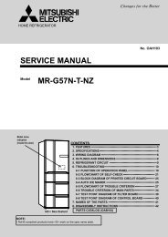
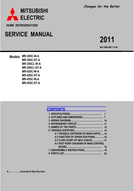
SERVICE MANUAL<br />
<strong>MR</strong>-385C-W-A<br />
<strong>MR</strong>-385C-ST-A<br />
<strong>MR</strong>-385CL-W-A<br />
<strong>MR</strong>-385CL-ST-A<br />
<strong>MR</strong>-<strong>420C</strong>-W-A<br />
<strong>MR</strong>-<strong>420C</strong>-ST-A<br />
<strong>MR</strong>-455C-W-A<br />
<strong>MR</strong>-455C-ST-A<br />
A………….......Australia & New Zea land<br />
CONTENTS<br />
Changes for the Better<br />
2011<br />
1. SPECIFICATIONS.................................................... 1<br />
2. OUTLINES AND DIMENSIONS.................................. 7<br />
3. WIRING DIAGRAM.................................................... 10<br />
4. REFRIGERANT CIRCUIT........................................... 11<br />
5. NAMES OF THE PARTS........................................... 13<br />
6. TROUBLE SHOOTING.............................................. 14<br />
6.1 TROUBLE CRITERION OF MAIN PARTS....... 14<br />
6.2 FUNCTION OF OPERATION PANEL.............. 16<br />
6.3 FLOW CHART OF SELF-CHECK.................... 17<br />
6.4 TEST POINT DIAGRAM OF MAIN CONTROL<br />
BOARD........................................................ 18<br />
7. DISASSEMBLY INSTRUCTIONS............................... 19<br />
8. PARTS LIST............................................................ 22<br />
NO.SM-RE-1130
1 SPECIFICATIONS<br />
1.1 SPECIFICATIONS<br />
<strong>MR</strong>-385C-A<br />
<strong>MR</strong>-385CL-A<br />
Power supply 230/240V 50Hz<br />
Total capacity (Gross (AS)) L<br />
385 (F : 130 R : 255)<br />
Dimensions (HXWXD) mm. 1587 x 687 x 694<br />
Cabinet Acrylic resin coated steel<br />
Food liner ABS resin<br />
Cabinet Foamed cyclopentane<br />
Insulation Freezer door Foamed cyclopentane<br />
Refrigerator door Foamed cyclopentane<br />
Cooling system Freezer Forced air convection<br />
Refrigerator Surround cooling,multi air flow,front air flow<br />
Evaporator Fin and tube type<br />
Condenser Concealed type<br />
Defrost system Automatic (Heater defrost)<br />
Drain Automatic (drainage)<br />
Temperature control system Automatic control<br />
Refrigerator room light 240V 15W (E12)<br />
Ice tray 1 pc.<br />
Ice box 1 pc.<br />
Freezer pocket 2 pcs.<br />
Slide chilled case 1 pc.<br />
Crystal shelf (F) 1 pc.<br />
Glass shelf (R) 3 pcs.<br />
Accessories Free pocket 1 pc.<br />
Egg rack 2 pcs.<br />
Adjust pocket 2 pcs.<br />
Bottle pocket 2 pcs.<br />
Vegetable case 1 pc.<br />
Tray V 1 pc.<br />
Drain pan 1 pc.<br />
Bottle stopper 1 pc.<br />
Weight Unit kg 68<br />
Shipping kg 74<br />
1
<strong>MR</strong>-<strong>420C</strong>-A<br />
Power supply 230/240V 50Hz<br />
Total capacity (Gross (AS)) L<br />
420 (F : 130 R : 290)<br />
Dimensions (HXWXD) mm. 1692 x 687 x 694<br />
Cabinet Acrylic resin coated steel<br />
Food liner ABS resin<br />
Cabinet Foamed cyclopentane<br />
Insulation Freezer door Foamed cyclopentane<br />
Refrigerator door Foamed cyclopentane<br />
Cooling system Freezer Forced air convection<br />
Refrigerator Surround cooling,multi air flow,front air flow<br />
Evaporator Fin and tube type<br />
Condenser Concealed type<br />
Defrost system Automatic (Heater defrost)<br />
Drain Automatic (drainage)<br />
Temperature control system Automatic control<br />
Refrigerator room light 240V 15W (E12)<br />
Ice tray 1 pc.<br />
Ice box 1 pc.<br />
Freezer pocket 2 pcs.<br />
Slide chilled case 1 pc.<br />
Crystal shelf (F) 1 pc.<br />
Glass shelf (R) 3 pcs.<br />
Accessories Free pocket 1 pc.<br />
Egg rack 2 pcs.<br />
Adjust pocket 2 pcs.<br />
Bottle pocket 2 pcs.<br />
Vegetable case 1 pc.<br />
Tray V 1 pc.<br />
Drain pan 1 pc.<br />
Bottle stopper 1 pc.<br />
Weight Unit kg 73<br />
Shipping kg 78<br />
2
<strong>MR</strong>-455C-A<br />
Power supply 230/240V 50Hz<br />
Total capacity (Gross (AS)) L<br />
454 (F : 130 R : 324)<br />
Dimensions (HXWXD) mm. 1802 x 687 x 694<br />
Cabinet Acrylic resin coated steel<br />
Food liner ABS resin<br />
Cabinet Foamed cyclopentane<br />
Insulation Freezer door Foamed cyclopentane<br />
Refrigerator door Foamed cyclopentane<br />
Cooling system Freezer Forced air convection<br />
Refrigerator Surround cooling,multi air flow,front air flow<br />
Evaporator Fin and tube type<br />
Condenser Concealed type<br />
Defrost system Automatic (Heater defrost)<br />
Drain Automatic (drainage)<br />
Temperature control system Automatic control<br />
Refrigerator room light 240V 15W (E12)<br />
Ice tray 2 pcs.<br />
Ice box 1 pc.<br />
Freezer pocket 2 pcs.<br />
Slide chilled case 1 pc.<br />
Crystal shelf (F) 1 pc.<br />
Glass shelf (R) 4 pcs.<br />
Accessories Free pocket 1 pc.<br />
Egg rack 2 pcs.<br />
Adjust pocket 3 pcs.<br />
Bottle pocket 2 pcs.<br />
Vegetable case 1 pc.<br />
Tray V 1 pc.<br />
Drain pan 1 pc.<br />
Bottle stopper 1 pc.<br />
Weight Unit kg 75<br />
Shipping kg 83<br />
3
1.2 ELECTRICAL PARTS SPECIFICATION<br />
<strong>MR</strong>-385C-A<br />
<strong>MR</strong>-385CL-A<br />
Model<br />
Power supply<br />
Compressor Rated input W<br />
PTC RELAY<br />
Starting current A<br />
Rated current A<br />
Winding resistance (A.T. : 20 o C)<br />
Model<br />
Motor protector Ambient temperature o C<br />
Running capacitor<br />
Time Sec.<br />
Current A<br />
Capillary tube mm.<br />
Dehydrant Molecular sieve g<br />
Refrigerant HFC. 134a g<br />
Defrosting control Defrosting timer<br />
Heater Defrost heater<br />
Deodorition<br />
Fan motor<br />
Temperature control<br />
Defrost finish o C<br />
Thermal fuse o C<br />
Model<br />
Type<br />
Rate voltage<br />
Input Power W<br />
Revolution r.p.m<br />
Model Freezer Refrigerator (MM1-6177)<br />
Dial position ON OFF OPEN SHUT<br />
Warmer<br />
Normal<br />
Colder<br />
DHS66C10RAW<br />
113/113.5(220/240V 50Hz)<br />
7.78/8.55(220/240V 50Hz)<br />
0.70/0.64(220/240V 50Hz)<br />
18.4 Ω(Main) / 18.5 Ω(Aux)<br />
PTH7M330MD2<br />
5TM222NFBYY<br />
12V DC<br />
4.2 ( at Vs 4.3V)<br />
2300 +10%( at Vs 4.3V)<br />
o C -14.6 -17.6 - 3.5<br />
o C -18.8 -21.8 MAX 5.0 -1.0 + 1.5<br />
o C -23 -26 - -12.5<br />
4<br />
220/240V 50Hz<br />
25<br />
16 MAX<br />
6.7<br />
4µF 400VAC<br />
∅ 1.8 X ∅ 0.65 X 2350<br />
10<br />
170<br />
Control board<br />
Thermister 14 + 1.5<br />
73<br />
384 Ω (240V 150W)<br />
Filter<br />
FBA12J12VXC<br />
DC brushless
<strong>MR</strong>-<strong>420C</strong>-A<br />
Model<br />
Power supply<br />
Compressor Rated input W<br />
PTC RELAY<br />
Starting current A<br />
Rated current A<br />
Winding resistance (A.T. : 20 o C)<br />
Model<br />
Motor protector Ambient temperature o C<br />
Running capacitor<br />
Time Sec.<br />
Current A<br />
Capillary tube mm.<br />
Dehydrant Molecular sieve g<br />
Refrigerant HFC. 134a g<br />
Defrosting control Defrosting timer<br />
Heater Defrost heater<br />
Deodorition<br />
Fan motor<br />
Temperature control<br />
Defrost finish o C<br />
Thermal fuse o C<br />
Model<br />
Type<br />
Rate voltage<br />
Input Power W<br />
Revolution r.p.m<br />
Model Freezer Refrigerator (MM1-6177)<br />
Dial position ON OFF OPEN SHUT<br />
Warmer<br />
Normal<br />
Colder<br />
DHS66C10RAW<br />
113/113.5(220/240V 50Hz)<br />
7.78/8.55(220/240V 50Hz)<br />
0.70/0.64(220/240V 50Hz)<br />
18.4 Ω(Main) / 18.5 Ω(Aux)<br />
PTH7M330MD2<br />
16 MAX<br />
o C -14.6 -17.6 - 3.5<br />
o C -18.8 -21.8 MAX 5.0 -1.0 + 1.5<br />
o C -23 -26 - -12.5<br />
5<br />
220/240V 50Hz<br />
5TM222NFBYY<br />
25<br />
6.7<br />
4µF 400VAC<br />
∅ 1.8 X ∅ 0.65 X 2350<br />
10<br />
175<br />
Control board<br />
Thermister 14 + 1.5<br />
73<br />
384 Ω (240V 150W)<br />
Filter<br />
FBA12J12VXC<br />
DC brushless<br />
12V DC<br />
4.2 ( at Vs 4.3V)<br />
2300 +10%( at Vs 4.3V)
<strong>MR</strong>-455C-A<br />
Model<br />
Power supply<br />
Compressor Rated input W<br />
PTC RELAY<br />
Starting current A<br />
Rated current A<br />
Winding resistance (A.T. : 20 o C)<br />
Model<br />
Motor protector Ambient temperature o C<br />
Running capacitor<br />
Time Sec.<br />
Current A<br />
Capillary tube mm.<br />
Dehydrant Molecular sieve g<br />
Refrigerant HFC. 134a g<br />
Defrosting control Defrosting timer<br />
Heater Defrost heater<br />
Deodorition<br />
Fan motor<br />
Temperature control<br />
Defrost finish o C<br />
Thermal fuse o C<br />
Model<br />
Type<br />
Rate voltage<br />
Input Power W<br />
Revolution r.p.m<br />
Model Freezer Refrigerator (MM1-6177)<br />
Dial position ON OFF OPEN SHUT<br />
Warmer<br />
Normal<br />
Colder<br />
DHS66C10RAW<br />
113/113.5(220/240V 50Hz)<br />
7.78/8.55(220/240V 50Hz)<br />
0.70/0.64(220/240V 50Hz)<br />
18.4 Ω(Main) / 18.5 Ω(Aux)<br />
4µF 400VAC<br />
∅ 1.8 X ∅ 0.65 X 2350<br />
Filter<br />
FBA12J12VXC<br />
DC brushless<br />
12V DC<br />
4.2 ( at Vs 4.3V)<br />
2300 +10%( at Vs 4.3V)<br />
o C -14.6 -17.6 - 3.5<br />
o C -18.8 -21.8 MAX 5.0 -1.0 + 1.5<br />
o C -23 -26 - -12.5<br />
6<br />
220/240V 50Hz<br />
PTH7M330MD2<br />
5TM222NFBYY<br />
25<br />
16 MAX<br />
6.7<br />
10<br />
180<br />
Control board<br />
Thermister 14 + 1.5<br />
73<br />
384 Ω (240V, 150W)
2 OUTLINES AND DIMENSIONS<br />
<strong>MR</strong>-385C-A<br />
<strong>MR</strong>-385CL-A<br />
1591<br />
685<br />
700<br />
1591<br />
7<br />
PLUG CORD LENGTH<br />
1950<br />
REQUIRED SPACE FOR INSTALLATION<br />
Unit : mm
<strong>MR</strong>-<strong>420C</strong>-A<br />
1696<br />
685<br />
700<br />
1696<br />
PLUG CORD LENGTH<br />
1950<br />
REQUIRED SPACE FOR INSTALLATION<br />
8<br />
Unit : mm
<strong>MR</strong>-455C-A<br />
1806<br />
685<br />
700<br />
1806<br />
PLUG CORD LENGTH<br />
1950<br />
REQUIRED SPACE FOR INSTALLATION<br />
9<br />
Unit : mm
3 WIRING DIAGRAM<br />
<strong>MR</strong>-385C-A<br />
<strong>MR</strong>-385CL-A<br />
<strong>MR</strong>-<strong>420C</strong>-A<br />
<strong>MR</strong>-455C-A<br />
(SKELETON WIRING DIAGRAM)<br />
10
4 REFRIGERANT CIRCUIT<br />
<strong>MR</strong>-385C-A<br />
<strong>MR</strong>-385CL-A<br />
11
<strong>MR</strong>-<strong>420C</strong>-A<br />
<strong>MR</strong>-455C-A<br />
12
5 NAMES OF PARTS<br />
<strong>MR</strong>-385C-A <strong>MR</strong>-<strong>420C</strong>-A <strong>MR</strong>-455C-A<br />
<strong>MR</strong>-385CL-A<br />
13
6 TROUBLE SHOOTING<br />
6.1 TROUBLE CRITERION OF MAIN PARTS<br />
<strong>MR</strong>-385C-A <strong>MR</strong>-385CL-A <strong>MR</strong>-<strong>420C</strong>-A <strong>MR</strong>-455C-A<br />
Components/<br />
Part Name<br />
Compressor<br />
Run capacitor<br />
Motor<br />
protector<br />
PTC RELAY<br />
Model<br />
Rated input<br />
Starting current<br />
Rated current<br />
Auxilialy<br />
wiring<br />
Main wiring<br />
Auxiliary wiring<br />
Check Method and Criterion<br />
Measure the resistance with a tester.<br />
(Ambient temperature: Room temperature 15 o C ~ 25 o C)<br />
5<br />
6<br />
3<br />
113/113.5(220/240V 50Hz)<br />
7.78/8.55(220/240V 50Hz)<br />
0.70/0.64(220/240V 50Hz)<br />
In the control<br />
Rated input 400VAC<br />
panel of the<br />
Measure the resistance with a tester. refrigerator<br />
Model<br />
PTH7M330MD2<br />
Measure the resistance with a tester.<br />
(Ambient temperature: Room temperature 15 o C ~ 25 o C)<br />
Normal<br />
DHS66C10RAW<br />
Normal<br />
33 Ω (Approx.)<br />
As PTC Relay has been heated while refrigerator is running be sure<br />
to measure the resistance after the thermistor has got cool enough.<br />
Abnormal(faulty)<br />
Short (0Ω )<br />
Model<br />
Measure the resistance with a tester.(Ambient temperature: Room temperature 15 o C ~ 25 o 120 + 5<br />
C)<br />
o C<br />
61 + 9 o 5TM222NFBYY<br />
Connected Open<br />
Point Close<br />
C<br />
2<br />
6<br />
5<br />
W<br />
A<br />
A<br />
Main<br />
wiring<br />
2<br />
3<br />
Opened (∞ Ω )<br />
14<br />
Normal<br />
18.4 Ω (Approx.)<br />
18.5 Ω (Approx.)<br />
Normal Abnormal(faulty)<br />
Less than 1Ω<br />
Opened (∞ Ω )<br />
Abnormal(faulty)<br />
Abnormal<br />
(faulty)<br />
Opened(∞ Ω )<br />
or<br />
Short (0Ω)<br />
Opened (∞ Ω ) or Short (0Ω)<br />
Parts Mounted<br />
Position<br />
Compressor in<br />
the machine<br />
chamber at the<br />
rear side of<br />
the frame<br />
compartment<br />
Compressor in<br />
the machine<br />
chamber at the<br />
rear side of<br />
the frame<br />
Compressor in<br />
the machine<br />
chamber at the<br />
rear side of<br />
the frame
Components/<br />
Part Name<br />
Refrigerator<br />
fan motor<br />
Defrost<br />
Heater<br />
Thermistor<br />
Measure the resistance with a tester.(Ambient temperature:Room temperature 15 o C ~ 25 o C)<br />
In fan grille of the<br />
freezer compartment.<br />
In the drip tray under<br />
the evaporator of the<br />
freezer compartment<br />
Resistance measured under Defrost thermistor<br />
the ambient temperature from(kΩ)<br />
-50: to +50: 35<br />
Thermistor resistance valves against<br />
temperature<br />
at the muffler<br />
of evaporator<br />
30<br />
Outside air thermistor in freezer compartment.<br />
1. 200" to 500k"<br />
............normal 25<br />
Freezer thermistor at<br />
2. Out of the above range thermistor,<br />
fan grille of freezer<br />
20 Defrost<br />
............abnormal compartment.<br />
5<br />
Thermistor Thermistor Check Check Procedure<br />
Procedure<br />
0<br />
Thermistor resistance will vary<br />
-20<br />
with the change of temperature.<br />
-10 0 10<br />
Temperature<br />
20 30<br />
Take the temperature around the thermistor,<br />
and then measure resistance using a tester.<br />
The relation of resistance and temperature is as shown on<br />
the above graph.<br />
Check Method and Criterion Parts Mounted Position<br />
Normal<br />
Between 3 - 1 (GND<br />
and IC Power ) :<br />
About 25kΩ<br />
Normal<br />
384Ω (Approx.)<br />
Resistance<br />
Model<br />
Type<br />
FBA12J12VXC<br />
DC brushless<br />
Abnormal (faulty)<br />
Between 3-1 : open( ∞ Ω )<br />
or<br />
between 2-1 : short ( 0 Ω)<br />
Rated input 150 W<br />
Measure the resistance with a tester.<br />
(Ambient temperature:Room temperature 15o C ~ 25 o Power ON after defrosting<br />
Operation method<br />
(14 + 1.5<br />
C)<br />
o C or more)<br />
15<br />
10<br />
Freezer<br />
thermistor<br />
15<br />
Inner<br />
thermistor<br />
Abnormal (faulty)<br />
Opened ( ∞ Ω )<br />
Out air thermistor<br />
under hinge cover
6.2 2 2 TEST TEST POINT POINT DIAGRAM DIAGRAM OF OF OF MAIN MAIN CONTROL CONTROL BOARD<br />
BOARD<br />
<strong>MR</strong> <strong>MR</strong>--385 <strong>MR</strong> <strong>MR</strong> 385C-A 385<br />
<strong>MR</strong> <strong>MR</strong>-385 <strong>MR</strong> 385CL 385 385CL-A<br />
CL<br />
<strong>MR</strong> <strong>MR</strong>-420 <strong>MR</strong> <strong>420C</strong>-A 420<br />
<strong>MR</strong> <strong>MR</strong>-455 <strong>MR</strong> 455C-AA 455<br />
Compulsory defrosting<br />
The defrosting instantaneously begins<br />
when JP3 and JP4 of the control board<br />
short-circuited.<br />
However, defrosting doesn't begin<br />
when the temperature of the<br />
thermistor is 8.6℃ or over.<br />
Parts Name<br />
F./R.DOOR SW.<br />
DEF.THERMISTOR<br />
F.THERMISTOR<br />
TEMP.CONTROL BOARD<br />
↑<br />
5V COMMON<br />
CN5 Lead color<br />
7 PURPLE<br />
6 PINK<br />
5 BLUE<br />
4<br />
3 BROWN<br />
2 GRAY<br />
1 SKY BLUE<br />
16<br />
Self-Check LED<br />
Lead color Parts Name<br />
WHITE FAN MOTOR(Cont.terminal)<br />
YELLOW ↑ (FG)<br />
RED ↑ (VDD)<br />
BLACK ↑ (GND)<br />
CN4<br />
4<br />
3<br />
2<br />
Parts Name<br />
9<br />
DEFROST HEATER<br />
7<br />
ORANGE ROOM LIGHT (R)<br />
WHITE COMPRESSOR<br />
1<br />
1 GRAY COMMON<br />
Lead color<br />
RED<br />
CN1<br />
5<br />
3
6.3 6.3 LED LED trouble trouble display display and and check check point. point.<br />
6.3.1) Trouble is indicated by the blinking number of self-check LED.<br />
6.3.2) LED blinks as shown below.<br />
The blinking number of self-check LED specifies the trouble which has occurred.<br />
LED repeats to blinks as many times as the number specified for each trouble under this cycle:lighted for<br />
0.3 second/not lighted for 0.3 second.<br />
(Example)Malfunction of defrsot thermistor<br />
1time 2times 1time 2times<br />
ON 5 sec. 5 sec.<br />
OFF<br />
Cycle Cycle<br />
6.3.3) Check point and Repairing<br />
※When several troubles occur,smaller blinking number LED has priority to be indicated first.<br />
Check point<br />
Corrective Priority Repairing<br />
1.Check connector of control PCB CN5,<br />
Improve in contact<br />
relay connector 3 pin 1<br />
2.Check the resistance of thermistor Change part<br />
1.Check connector of control PCB CN5,<br />
Improve in contact<br />
relay connector 2 pin<br />
2<br />
2.Check the resistance of thermistor Change part<br />
1.Check connector of control PCB CN1,<br />
Improve in contact<br />
relay connector 3 pin and temp. fuse<br />
3<br />
2.Check the resistance of defrost heater Change part<br />
3.Check the resistance of temp. fuse Change part<br />
1.Check connector of control PCB CN4,<br />
Improve in contact<br />
relay connector 4 pin<br />
4<br />
2.Check the movement of fan motor Change part<br />
Change Control Board 5<br />
Analysis<br />
Cause<br />
Function display<br />
Open circuit or short<br />
circuit case<br />
Fault trouble of freezer thermistor<br />
1 time<br />
Open circuit or short<br />
circuit case<br />
Fault trouble of defrost thermistor<br />
2 times<br />
Defrost unfinished<br />
with in 2 hours<br />
Fault trouble of defrost heater<br />
3 times<br />
Lighting mode<br />
Don't rolling case<br />
Fault trouble of fan motor<br />
10 times<br />
Malfunction display<br />
LED display self-check<br />
17<br />
Out of control case<br />
Fault trouble of Memory<br />
(Control Board)<br />
16 times<br />
Caution<br />
1.Before plug in the AC power, Be ensure the comp had been off more than 20 min.<br />
2.The consider short circuit or open circuit of thermistor, resistance of open circuit is ∞ Ω, resistance of short circuit is 0 Ω.
6.4 Importance detail of fault analysis<br />
Flow chart of self - check<br />
1) Self - check monitor circuit<br />
For show the fault condition of refrigerator and clarify point. Therefore, self - check monitor control is provided<br />
that are able to monitor No. of blinking condition with electric circuit and electric part . Before disconnect power plug please<br />
confirm LED self - check .<br />
Refrigerator plug<br />
connect?<br />
Yes<br />
Self - check<br />
Mal Function Display<br />
(No .of blinking)<br />
Yes<br />
Check the fault point as<br />
malfunction list<br />
Disconnect power plug<br />
Repair the macfunction cause<br />
Connect power plug<br />
No<br />
No<br />
Connect power plug<br />
Caution<br />
No change on display<br />
1. As the part list below couldn't analysis by self - check , then<br />
please check by reference to trouble shooting page.<br />
- Dilapidation of door switch ,refrigerator room and freezer room.<br />
- Dilapidation of compressor and fan motor .<br />
2. If have malfunction when supply the power . Compressor and<br />
fan motor will not operate 20 minutes.<br />
2) Interval of self check analysis<br />
- Troubles of thermistor : will check always.<br />
- Trouble of defrost heater : will just analyse during defrost display only.<br />
(The period checking will analyse the defrost circuit after connect the plug 2 hours )<br />
18<br />
Normal operation
7<br />
DISASSEMBLY INSTRUCTIONS<br />
<strong>MR</strong>-385C-A <strong>MR</strong>-385CL-A <strong>MR</strong>-<strong>420C</strong>-A <strong>MR</strong>-455C-A<br />
Unplug the power cord before repairing and servicing<br />
OPERATING PROCEDURE<br />
1. Remove parts insider the Freezer room<br />
(1) Photo 1st Remove Crystal shelf Freezer,<br />
Ice corner tray assy, Ice tray, Ice box<br />
Fan Grille<br />
(2) Photo 2nd Remove screws for closing Lead cover F,<br />
Remove 2 Rivets From Fan grille<br />
(3) Photo 3rd Cut binder, remove poly bag, Take off<br />
connector lead wire.<br />
Bell mouth<br />
(4) Unhook the catches of the fan grille and the bell mouth,<br />
and separate the fan grille and the bell mouth.<br />
(See photo 4th.)<br />
Fan motor<br />
(5) Photo 4th Remove Fan motor after separated the fan<br />
grille and the bell mouth from bell mouth<br />
Defrost thermal fuse and Freezer thermistor<br />
(6) Photo 4th remove the connector and plug to take out<br />
the thermal fuse and thermistor freezer.After separated<br />
the fan grille and the bell mouth<br />
Defrost heater and Drip tray<br />
(7) Photo 5th Lift up evaporator and remove the defrost<br />
heater out of base after remove heater cover plate and<br />
drip tray<br />
Caution on assembly<br />
1. Insert the fan into the base of fan motor's shaft,<br />
check if the fan rotates with your finger.<br />
2. When inserted drip tray to effect to slacken the<br />
lead wire of defrost heater in order to prevent water<br />
from entering the glass tube.<br />
3. Attach defrost thermistor with muffler and tighten<br />
the binder.<br />
19<br />
Photo 1<br />
Photo 2<br />
Photo 3<br />
Photo 4<br />
Ice tray<br />
Ice box<br />
Photo 5<br />
Defrost heater<br />
Fan grille<br />
Binder<br />
Fan motor<br />
PHOTOS<br />
Rivets<br />
Crystal shelf F<br />
Ice corner tray assy<br />
Lead cover F<br />
Bag<br />
Screw<br />
Connector lead wire<br />
Thermal fuse<br />
Bell mouth<br />
Evaporator Def thermistor<br />
Heater roof<br />
Drip tray
2. Remove parts inside the refrigerator<br />
(1) Remove chilled case door and slide chilled case ,<br />
remove glass shelves of refrigerator room , remove<br />
the control panel<br />
(Photo 6)<br />
(2) Remove lamp cover R<br />
(Photo 6)<br />
(3) Remove screw and rivet , pull the control panel with<br />
to right refrigerator wall.<br />
(Photo 6)<br />
(4) Remove duct R assy, damper thermo is installed<br />
within it.<br />
(Photo 7)<br />
Remove the screw of damper thermo<br />
3. Remove the electric box cover<br />
(1) Take out screw (2 points) as photo 8<br />
(2) Take out screw (2 points)at left side and right side<br />
of electric box cover ,then pull the electric box cover<br />
as photo 9.<br />
Caution on assembly<br />
1. Be sure to use new sealing materials and tape for<br />
assembly.<br />
2. Attach the sealing material of PC board and<br />
protective moisture.<br />
OPERATING PROCEDURE PHOTOS<br />
attach the aluminium tape every times for<br />
3. Must put connector which contact must touch<br />
together as photo 10.<br />
20<br />
Photo 6<br />
Photo 7<br />
Screws<br />
Control panel<br />
Thermo dial R<br />
Temp control<br />
Photo 8<br />
Running capacitor<br />
PC board<br />
Lamp cover R<br />
Rivets<br />
Duct R assy<br />
Electric box cover<br />
Photo 10<br />
Screws<br />
Thermo dial F<br />
Photo 9<br />
Damper thermo<br />
Screws<br />
Connectors
4. Removing the compressor<br />
(1) Detach the drain pan.<br />
Compressor<br />
(2) Collect gas from the charge pipe on the high pressure side.<br />
(3) After collecting gas, cut the charge pipe on the low pressure side.<br />
(4) Detach the welded section of the discharge pipe and suction pipe<br />
(5) Replace the compressor and the dryer at a time. (The dryer should be the one packed with the compressor.)<br />
CAUTION ON ASSEMBLY<br />
OPERATING PROCEDURE<br />
After replacing the compressor be sure to evacuate the refrigerating cycle and charge gas into the charge pipe.<br />
After replacement check cooling operation and check the weld for gas leaking.<br />
w<br />
Charge pipe<br />
w<br />
U Washer<br />
: This mark shows welding point.<br />
21<br />
w<br />
Discharge pipe<br />
(High pressure side)<br />
Suction pipe<br />
w<br />
Binder<br />
Dryer
8 PARTS LIST<br />
DOOR, BODY PARTS<br />
<strong>MR</strong>-385C-A<br />
<strong>MR</strong>-385CL-A<br />
<strong>MR</strong>-<strong>420C</strong>-A<br />
<strong>MR</strong>-455C-A<br />
2<br />
3<br />
5<br />
6<br />
4<br />
7<br />
1<br />
8<br />
6<br />
2<br />
5<br />
7<br />
1<br />
3<br />
4<br />
8<br />
22<br />
9<br />
9<br />
10<br />
10<br />
12<br />
12<br />
13<br />
11<br />
13<br />
11
Q'TY/UNIT<br />
NO. PART NO. RoHS PART NAME SPEC <strong>MR</strong>-385C-A <strong>MR</strong>-385CL-A <strong>MR</strong>-<strong>420C</strong>-A <strong>MR</strong>-455C-A<br />
W ST W ST W ST W ST<br />
1 KIEL75131 FREEZER POCKET PRINT 1 1 1 1 1 1 1 1<br />
2 KIEL76131 FREEZER POCKET 1 1 1 1 1 1 1 1<br />
3 KIE401115 EGG RACK 2 2 2 2 2 2 2 2<br />
4 KIEL75118 FREE POCKET 1 1 1 1 1 1 1 1<br />
5 KIEL75159 ADJUST POCKET 2 2 2 2 2 2 3 3<br />
6 KIEL75124 BOTTLE POCKET PRINT 1 1 1 1 1 1 1 1<br />
7 KIEL76124 BOTTLE POCKET 1 1 1 1 1 1 1 1<br />
8 KIEH88143 BOTTLE STOPPER 1 1 1 1 1 1 1 1<br />
KIERM0001 1 1 1<br />
9<br />
KIER74001<br />
KIERM2001<br />
<br />
<br />
DOOR F<br />
1<br />
1<br />
1 1<br />
KIERM3001 1<br />
10 KIEH79111 MAGNET GASKET ASSY (F) 1 1 1 1 1 1 1 1<br />
11<br />
KIEG05741<br />
KIEPE4741<br />
<br />
<br />
CATCHER RH<br />
CATCHER LH<br />
1 1<br />
1 1<br />
1 1 1 1<br />
KIEM98000 1<br />
KIEM73000 1<br />
KIEMA0000 1<br />
12<br />
KIEMA1000<br />
KIEMA2000<br />
<br />
<br />
DOOR R<br />
1<br />
1<br />
KIEM77000 1<br />
KIEMA4000 1<br />
KIEM80000 1<br />
KIEH79110 1 1 1 1<br />
13 KIEH82110 MAGNET GASKET ASSY (R)<br />
1 1<br />
KIEH85110 1 1<br />
14<br />
KIERN0031<br />
KIER72031<br />
<br />
<br />
BADGE ASSY<br />
1<br />
1<br />
1<br />
1<br />
1<br />
1<br />
1<br />
1<br />
RECOMMEND PART NO. 9, 10, 12, 13<br />
ABBREVIATION<br />
F<br />
R<br />
FREEZER ROOM<br />
REFRIGERATOR ROOM<br />
ENCIRCLED PART NUMBER ARE NOT SHOWN IN THE FIGURES.<br />
Remark<br />
- Country code : A= Australia and New Zealand<br />
- Colour code : W = White, ST = Stainless<br />
23<br />
PRICE/PI<br />
ECE(US$-<br />
FOB)
ACCESSORY PARTS<br />
<strong>MR</strong>-385C-A<br />
<strong>MR</strong>-385CL-A<br />
<strong>MR</strong>-<strong>420C</strong>-A<br />
<strong>MR</strong>-455C-A<br />
24<br />
29<br />
29
Q'TY/UNIT<br />
NO. PART NO. RoHS PART NAME<br />
SPEC <strong>MR</strong>-385C-A <strong>MR</strong>-385CL-A <strong>MR</strong>-<strong>420C</strong>-A <strong>MR</strong>-455C-A<br />
W ST W ST W ST W ST<br />
1 KIEMQ4662 BELL MOUTH 1 1 1 1 1 1 1 1<br />
2 KIEL75473 LAMP COVER (F) 1 1 1 1 1 1 1 1<br />
3 KIEH79663 FAN GRILLE 1 1 1 1 1 1 1 1<br />
4 KIEH79450 ICE CORNER ASSY 1 1 1 1 1 1 1 1<br />
KIEL75665 1 1 1 1<br />
5 KIEL79665 DUCT R ASSY<br />
1 1<br />
KIEL82665 1 1<br />
6 KIEL75411 SLIDE CHILLED CASE 1 1 1 1 1 1 1 1<br />
7 KIEM98850 CONTROL PANEL 1 1 1 1 1 1 1 1<br />
8<br />
KIEH79305<br />
KIEK67305<br />
<br />
<br />
THERMO DIAL (R)<br />
1 1 1 1 1 1<br />
1 1<br />
KIEL75853 1 1 1 1<br />
9 KIEL79853 CONTROL PANEL (SUB)<br />
1 1<br />
KIEL82853 1 1<br />
10<br />
KIEL75470<br />
KIEL79470<br />
<br />
<br />
LAMP COVER (R)<br />
1 1 1 1<br />
1 1 1 1<br />
11 KIEK66430 GLASS SHELF ( R ) 3 3 3 3 3 3 4 4<br />
12 KIEL75405 VEGETABLE CASE 1 1 1 1 1 1 1 1<br />
13 KIEH79435 DRAIN PAN 1 1 1 1 1 1 1 1<br />
14 KIE805794 CASTER SET 2 2 2 2 2 2 2 2<br />
15 KIEH79326 LEAD COVER F 1 1 1 1 1 1 1 1<br />
KIEHA5705 1 1 1<br />
16<br />
KIEH89705<br />
KIERM2705<br />
<br />
<br />
HINGE COVER<br />
1<br />
1<br />
1 1<br />
KIERM3705 1<br />
17<br />
KIEE94701<br />
KIEEA3701<br />
<br />
<br />
HINGE ASSY (UPPER)<br />
1 1<br />
1 1<br />
1 1 1 1<br />
18 KIEH79431 CRYSTAL SHELF (F) 1 1 1 1 1 1 1 1<br />
19 KIEL75440 ICE TRAY 1 1 1 1 1 1 1 1<br />
20 KIEH79467 ICE BOX 1 1 1 1 1 1 1 1<br />
21<br />
KIEE94746<br />
KIEEA3746<br />
<br />
<br />
STOPPER HINGE<br />
2 2<br />
2 2<br />
2 2 2 2<br />
22<br />
KIEMQ4703<br />
KIEMA0703<br />
<br />
<br />
HINGE ASSY (MIDDLE)<br />
1 1<br />
1 1<br />
1 1 1 1<br />
23 KIEL75418 CHILLED CASE DOOR 1 1 1 1 1 1 1 1<br />
24 KIEH79315 THERMO DIAL (F) 1 1 1 1 1 1 1 1<br />
25<br />
KIEL75702<br />
KIEMA0702<br />
<br />
<br />
HINGE ASSY (LOWER)<br />
1 1<br />
1 1<br />
1 1 1 1<br />
26 KIEH79795 CASTER ASSY 2 2 2 2 2 2 2 2<br />
27 KIEC02460 ADJUST BOLT 2 2 2 2 2 2 2 2<br />
KIEJ81730 1 1 1<br />
28<br />
KIEJ82730<br />
KIEJ93730<br />
<br />
<br />
KICK PLATE<br />
1<br />
1<br />
1 1<br />
KIEJ94730 1<br />
29 KIEK88468 TRAY V 1 1 1 1 1 1 1 1<br />
RECOMMEND PART NO. 6, 8 ,11, 12, 18, 19, 20<br />
ABBREVIATION<br />
F FREEZER ROOM V BETWEEN REFRIGERATOR ROOM AND VEGETABLE ROOM<br />
R REFRIGERATOR ROOM<br />
25<br />
PRICE/PIEC<br />
E(US$-FOB)
ELECTRICIAL PARTS AND UNIT PARTS<br />
<strong>MR</strong>-385C-A<br />
<strong>MR</strong>-385CL-A<br />
<strong>MR</strong>-<strong>420C</strong>-A<br />
<strong>MR</strong>-455C-A<br />
1<br />
2<br />
3<br />
4<br />
5<br />
6<br />
7<br />
8<br />
9<br />
10<br />
11<br />
12<br />
14<br />
15<br />
16<br />
13<br />
26<br />
17<br />
18<br />
19<br />
20<br />
21<br />
22<br />
20<br />
23<br />
24<br />
25<br />
26<br />
27
Q'TY/UNIT<br />
NO. PART NO. RoHS PART NAME<br />
SPEC <strong>MR</strong>-385C-A <strong>MR</strong>-385CL-A <strong>MR</strong>-<strong>420C</strong>-A <strong>MR</strong>-455C-A<br />
W ST W ST W ST W ST<br />
1 KIENF2336 THERMAL FUSE ( DEF ) 1 1 1 1 1 1 1 1<br />
2 KIEMQ4995 EVAPORATOR 1 1 1 1 1 1 1 1<br />
3 KIEH79537 HEATER ROOF 1 1 1 1 1 1 1 1<br />
4 KIEHM2392 DEFROST HEATER ASSY<br />
240V, 150W NOT<br />
DEODORIZER<br />
1 1 1 1 1 1 1 1<br />
5 KIEB66397 HEATER COVER 1 1 1 1 1 1 1 1<br />
6 KIE402360 LAMP E12 240V 15W 1 1 1 1 1 1 1 1<br />
7 KIEH79538 DRIP TRAY 1 1 1 1 1 1 1 1<br />
8 KIEH79301 DAMPER THERMO MM1-6177 1 1 1 1 1 1 1 1<br />
9 KIEH61399 FILTER 1 1 1 1 1 1 1 1<br />
10 KIELR4346 RUNNING CAPACITOR 4µF 400VAC 1 1 1 1 1 1 1 1<br />
11 KIEM98326 ELECTRIC COVER BOX 1 1 1 1 1 1 1 1<br />
12 KIEMQ4326 ELECTRIC BOX 1 1 1 1 1 1 1 1<br />
13 KIERN0339 REFCON ASSY 1 1 1 1 1 1 1 1<br />
14 KIEPM7277 COMPRESSOR DHS66C10RAW 1 1 1 1 1 1 1 1<br />
15 KIE902735 U WASHER 3 3 3 3 3 3 3 3<br />
16 KIEE76797 RUBBER MOUNT 4 4 4 4 4 4 4 4<br />
17 KIEMQ4312 THERMISTOR (DEF) 1 1 1 1 1 1 1 1<br />
18 KIEB66378 THERMISTOR (F) 1 1 1 1 1 1 1 1<br />
19 KIEMQ4320 FAN MOTOR 1 1 1 1 1 1 1 1<br />
20 KIEMQ4363 LAMP SWITCH 2 2 2 2 2 2 2 2<br />
21 KIEMQ4386 LAMP SOCKET(R) 1 1 1 1 1 1 1 1<br />
22 KIEM98382 TEMP CONTROL BOARD 1 1 1 1 1 1 1 1<br />
23 KIEM98354 PLUG CORD ASSY 1 1 1 1 1 1 1 1<br />
24 KIEAA1980 DRYER 4AXH-9,10GR 1 1 1 1 1 1 1 1<br />
25 KIERL4341 PROTECTOR COVER 1 1 1 1 1 1 1 1<br />
26 KIE<strong>MR</strong>7340 MOTOR PROTECTOR 5TM222NFBYY-53 1 1 1 1 1 1 1 1<br />
27 KIEE76330 PTC RELAY PTH7M330MD2 1 1 1 1 1 1 1 1<br />
RECOMMEND PART NO. 1, 4, 6, 8, 10, 13, 17, 18, 20, 24, 26, 27<br />
ABBREVIATION<br />
F<br />
R<br />
FREEZER ROOM<br />
REFRIGERATOR ROOM<br />
DEF DEFROST<br />
27<br />
PRICE/PIEC<br />
E(US$-FOB)
PACKING PARTS<br />
<strong>MR</strong>-385C-A<br />
<strong>MR</strong>-385CL-A<br />
<strong>MR</strong>-<strong>420C</strong>-A<br />
<strong>MR</strong>-455C-A<br />
3<br />
TOP CUSHION MID<br />
1 2<br />
3<br />
L<br />
R<br />
6<br />
BOTTOM CUSHION<br />
2<br />
TOP CUSHION<br />
7<br />
C.F.B PALLET<br />
NO STEP ON<br />
1<br />
C.F.B BOX ASSY<br />
28<br />
8<br />
C.F.B TOP COVER<br />
5<br />
SIDE CUSHION ASSY<br />
4<br />
PACKING COVER
Q'TY/UNIT<br />
NO. PART NO. RoHS PART NAME SPEC <strong>MR</strong>-385C-A <strong>MR</strong>-385CL-A <strong>MR</strong>-<strong>420C</strong>-A <strong>MR</strong>-455C-A<br />
W ST W ST W ST W ST<br />
KIERM0970 1<br />
KIERM1970 1<br />
KIERM2970 1<br />
1<br />
KIERM3970<br />
KIERM6970<br />
<br />
<br />
C.F.B BOX ASSY<br />
1<br />
1<br />
KIERM7970 1<br />
KIERM8970 1<br />
KIERM9970 1<br />
2 KIEL75979 TOP CUSHION 1 1 1 1 1 1 1 1<br />
3 KIEH79972 TOP CUSHION MID 1 1 1 1 1 1 1 1<br />
4 KIEG55973 PACKING COVER 1 1 1 1 1 1 1 1<br />
5 KIEJ81971 SIDE CUSHION ASSY 1 1 1 1 1 1 1 1<br />
6 KIEH79978 BOTTOM CUSHION 1 1 1 1 1 1 1 1<br />
7 KIEH79974 C.F.B PALLET 1 1 1 1 1 1 1 1<br />
8 KIEH79975 C.F.B TOP COVER 1 1 1 1 1 1 1 1<br />
29<br />
PRICE/PIECE<br />
(US$-FOB)
MITSUBISHI ELECTRIC CORPORATATION<br />
HEAD OFFICE : MITSUBISHI DENKI BLDG., MARUNOUCHI,TOKYO 100. TELEX : J24532 CABLE MELCO TOKYO<br />
Distributed by<br />
MITSUBISHI ELECTRIC AUSTRALIA PTY LTD.<br />
(Incorporated in New South Wales) ABN 58 001 215 792<br />
New South Wales : Queensland: South Australia /<br />
348 Victoria Road, Unit 12, 469 Northern territory :<br />
Rydalmere NSW 2116 Nudgee Road, Suite 1, 224 Glen Osmond Road<br />
Ph : (02) 9684 7777 Hendra QLD , 4011 FULLARTON SA 5063<br />
Fax : (02) 9898 1043 Ph : (07) 3263 2000 Ph: (08) 8338 1001<br />
Fax : (07) 3630 1888 Fax : (08) 8338 0501<br />
Western Australia : Victoria / Tasmania : Far North<br />
329 Collier Road, Building 28, Omnico bus. Park Queensland:<br />
Bassendean WA 6054 270 Ferntree Gully Road, Capricorn Air,<br />
Ph : (08) 9377 3400 Notting Hill 3168 13 Mackley St,<br />
Fax : (08) 9377 3499 Ph : (03) 9535 7800 Garbutt 4814<br />
Fax : (03) 9535 7801 Ph: (07) 4775 5222<br />
Fax : (07) 4775 5303<br />
Distributed by<br />
BLACK DIAMOND TECHNOLOGIES LIMITED (BDT)<br />
Wellington Office (Head Office) Auckland Office Christchurch Office<br />
1 Parliament Street Unit1, 4 Walls Road Suite 2, Level 1<br />
PO Box 30-772 Penrose 37 Manderville Street<br />
Lower Hutt Auckland PO Box 12-726 Christchurch PO Box 1604<br />
Ph : (04) 560 9100 Ph: (09) 526 9340 Ph : (03) 341 7052<br />
Fax : (04) 560 9133 Fax : (09) 526 9369 Fax : (03) 341 7054