SERVICE MANUAL REF-MR-255J-A,NZ - BDT
SERVICE MANUAL REF-MR-255J-A,NZ - BDT
SERVICE MANUAL REF-MR-255J-A,NZ - BDT

Create successful ePaper yourself
Turn your PDF publications into a flip-book with our unique Google optimized e-Paper software.
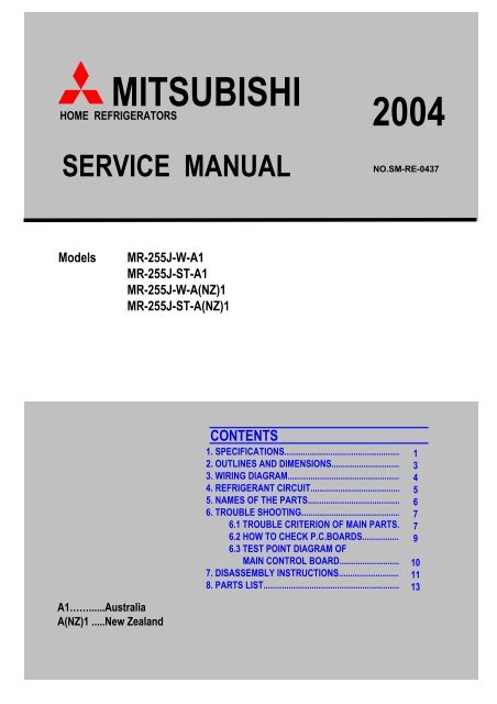
MITSUBISHI<br />
HOME <strong>REF</strong>RIGERATORS<br />
<strong>SERVICE</strong> <strong>MANUAL</strong><br />
Models<br />
A1……......Australia<br />
A(<strong>NZ</strong>)1 .....New Zealand<br />
<strong>MR</strong>-<strong>255J</strong>-W-A1<br />
<strong>MR</strong>-<strong>255J</strong>-ST-A1<br />
<strong>MR</strong>-<strong>255J</strong>-W-A(<strong>NZ</strong>)1<br />
<strong>MR</strong>-<strong>255J</strong>-ST-A(<strong>NZ</strong>)1<br />
2004<br />
NO.SM-RE-0437<br />
CONTENTS<br />
1. SPECIFICATIONS.................................................... 1<br />
2. OUTLINES AND DIMENSIONS.................................. 3<br />
3. WIRING DIAGRAM.................................................... 4<br />
4. <strong>REF</strong>RIGERANT CIRCUIT........................................... 5<br />
5. NAMES OF THE PARTS........................................... 6<br />
6. TROUBLE SHOOTING.............................................. 7<br />
6.1 TROUBLE CRITERION OF MAIN PARTS....... 7<br />
6.2 HOW TO CHECK P.C.BOARDS...................... 9<br />
6.3 TEST POINT DIAGRAM OF<br />
MAIN CONTROL BOARD.............................. 10<br />
7. DISASSEMBLY INSTRUCTIONS............................... 11<br />
8. PARTS LIST............................................................. 13
1 SPECIFICATION<br />
1.1 SPECIFICATION<br />
<strong>MR</strong>-<strong>255J</strong>-A1<br />
<strong>MR</strong>-<strong>255J</strong>-A(<strong>NZ</strong>)1<br />
Power supply 230/240V 50Hz<br />
Total capacity (Gross (AS)) L 255 (F:76 R:179)<br />
Dimensions (HXWXD) mm. 1571x555x616<br />
Cabinet Acrylic resin coated steel<br />
Food liner ABS resin<br />
Cabinet Foamed cyclopenthane<br />
Insulation Freezer door Foamed cyclopenthane<br />
Refrigerator door Foamed cyclopenthane<br />
Cooling system<br />
Freezer<br />
Refrigerator<br />
Forced air convection<br />
Forced air convection<br />
Evaporator Fin and tube type<br />
Condenser Concealed type<br />
Defrost system Automatic (Heater defrost)<br />
Drain Automatic (drainage)<br />
Temperature control system Automatic control<br />
Refrigerator room light 240V, 15W (E12)<br />
Ice tray 1 pc.<br />
Ice box 1 pc.<br />
Freezer pocket 1 pc.<br />
Slide chilled case 1 pc.<br />
Crystal shelf ( F ) 2 pcs.<br />
Crystal shelf ( RS ) 2 pcs.<br />
Crystal shelf ( RL ) 2 pcs.<br />
Accessories Free pocket 1 pc.<br />
Egg rack (large) 1 pc.<br />
Egg rack (small) 1 pc.<br />
Mini pocket 2 pcs.<br />
Bottle pocket 2 pcs.<br />
Bottle stopper 1 pc.<br />
Vegetable case 1 pc.<br />
Drain pan 1 pc.<br />
Weight<br />
Unit<br />
Shipping<br />
kg<br />
kg<br />
49<br />
54<br />
- 1 -
1.2 ELECTRICAL PARTS SPECIFICATION<br />
<strong>MR</strong>-<strong>255J</strong>-A1<br />
<strong>MR</strong>-<strong>255J</strong>-A(<strong>NZ</strong>)1<br />
Model<br />
Rated input<br />
Starting current<br />
W<br />
A<br />
Running current<br />
Winding resistance (A.T.20<br />
A<br />
o PTC relay<br />
C)<br />
Model<br />
Ambient temperature o Time<br />
C<br />
Sec<br />
Running capacitor<br />
Current A<br />
Capillary tube mm.<br />
Dehydrant Molecular sieve g<br />
Refrigerant HFC-134a<br />
Defrosting timer<br />
g<br />
Defrost finish o C<br />
Thermal fuse o Compressor<br />
Motor protector<br />
Defrosting control<br />
C<br />
Heater<br />
Defrost heater<br />
Deodorizing function of defrost heater<br />
Model<br />
Type<br />
Fan motor Number of poles<br />
Input W<br />
Revolution r.p.m<br />
Temperature<br />
control<br />
D57C10RAW5<br />
220/240V 50Hz<br />
112/116 (220/240V 50Hz)<br />
6.92/7.5 (220/240V 50Hz)<br />
0.76/0.72 (220/240V 50Hz)<br />
18.1Ω(Main) / 31.7Ω(Aux)<br />
PTH7M330MD2<br />
MM3-17GDF<br />
25<br />
Below 18<br />
5.0<br />
4µF 400VAC<br />
∅ 1.8 X ∅ 0.65 X 2350<br />
10<br />
145<br />
Control board<br />
Thermistor 14+1.5<br />
73<br />
384Ω (240V, 150W)<br />
Equipped<br />
MH07DX5-TJA5<br />
Single phase<br />
2p<br />
Below 6.7 (220V, 50Hz)<br />
2250+200 (220V, 50Hz)<br />
Model<br />
Thermistor<br />
Dial position ON OFF<br />
Warmer o<br />
C -13.7 -19<br />
Normal o<br />
C -16.9 -22.9<br />
Colder o<br />
C -20.4 -27.5<br />
- 2 -
2 OUTLINES AND DIMENTIONS<br />
<strong>MR</strong>-<strong>255J</strong>-A1<br />
<strong>MR</strong>-<strong>255J</strong>-A(<strong>NZ</strong>)1<br />
426<br />
931<br />
170<br />
17<br />
57<br />
555 (Display)<br />
550 (Cabinet)<br />
490 (Cabinet)<br />
125 115<br />
137<br />
179<br />
105<br />
100<br />
114<br />
124<br />
208<br />
298<br />
230<br />
320<br />
310<br />
616 (Display)<br />
50<br />
1571 (Display)<br />
52<br />
393<br />
915<br />
100<br />
- 3 -<br />
1571<br />
1950<br />
470<br />
448<br />
486<br />
447<br />
616<br />
PLUG CORD LENGTH<br />
SPACE REQUIRED FOR INSTALLATION<br />
52<br />
20<br />
555<br />
Unit : mm<br />
20<br />
441<br />
947
3 WIRING DIAGRAM<br />
<strong>MR</strong>-<strong>255J</strong>-A1<br />
<strong>MR</strong>-<strong>255J</strong>-A(<strong>NZ</strong>)1 (SKELETON WIRING DIAGRAM)<br />
(ACTUAL WIRING DIAGRAM)<br />
- 4 -
4 <strong>REF</strong>RIGERANT CIRCUIT<br />
<strong>MR</strong>-<strong>255J</strong>-A1<br />
<strong>MR</strong>-<strong>255J</strong>-A(<strong>NZ</strong>)1<br />
- 5 -
5 NAMES OF THE PARTS<br />
<strong>MR</strong>-<strong>255J</strong>-A1<br />
<strong>MR</strong>-<strong>255J</strong>-A(<strong>NZ</strong>)1<br />
- 6 -
6 TROUBLE SHOOTING<br />
6.1 TROUBLE CRITERION OF MAIN PARTS<br />
<strong>MR</strong>-<strong>255J</strong>-A1<br />
<strong>MR</strong>-<strong>255J</strong>-A(<strong>NZ</strong>)1<br />
Components/<br />
Part Name<br />
Check Methode and Criterion<br />
Parts Mounted<br />
Position<br />
Compressor Compressor in the<br />
Model<br />
D57C10RAW5 machine chamber<br />
Rate input W 112/116 ( 220/240V 50Hz) at the rear side of<br />
Startting current A 6.92/7.5 ( 220/240V 50Hz) the frame<br />
Running current A 0.76/0.72 ( 220/240V 50Hz)<br />
Measure the resistance with a tester.<br />
Main wiring<br />
Auxiliary wiring<br />
(Ambient temperature: Room temperature 15 O C ~ 25 O C)<br />
Motor protector Compressor in<br />
Model MM3-17GDF the machine<br />
120+5 O C or more<br />
(5A or 5-18 second)<br />
chamber at the<br />
rear side of<br />
61+11 O Open<br />
Connected point<br />
Close<br />
C or less the frame.<br />
(Ambient temperature: Room temperature 15 O C ~ 25 O C)<br />
Normal<br />
(Approx.)<br />
31.7Ω<br />
(Aprrox.)<br />
Abnormal<br />
(faulty)<br />
Normal Abnormal(Faulty)<br />
Less than 1Ω Opened (∞ Ω)<br />
PTC Relay Compressor in<br />
Model PTH7M330MD2 the machine<br />
Measure the resistance with a tester. chamber at the<br />
(Ambient temperature: Room temperature 15 O C ~ 25 O C) rear side of<br />
18.1Ω<br />
Opened(∞ Ω )<br />
or<br />
Short (0Ω)<br />
As PTC Relay thermistor has<br />
been heated while refrigerator<br />
Normal Abnormal(Faulty)<br />
is running, be sure to measure<br />
the resistance after the thermistor<br />
has got cool enough.<br />
33Ω (Approx.)<br />
- 7 -<br />
Opened (∞ Ω ) or Short (0Ω)<br />
the frame.
Components/<br />
Part Name<br />
Check Methode and Criterion<br />
Refrigerator Fan grill of the<br />
fan motor Model MH07DX5-TJA5<br />
Measure the resistance with a tester.<br />
(Ambient temperature: Room temperature 15 O C ~ 25 O Parts Mounted<br />
Position<br />
freezer compartment.<br />
C)<br />
830Ω (Approx.) Opened (∞ Ω ) or Short (0Ω)<br />
Defrost heater Rated input W 150 In drip tray under<br />
Power ON after defrosting<br />
(14+1.5<br />
evaporator of the<br />
O operation method<br />
C or more) freezer compartment.<br />
Measure the resistance with a tester.<br />
(Ambient temperature: Room temperature)<br />
Opened (∞ Ω )<br />
Thermistor ● Resistance measured under DEF thermistors<br />
the ambient temperature from<br />
radiator of the freezer<br />
-50: to +50:<br />
compartment.<br />
1. 200" to 500k"<br />
R-thermister , control<br />
................Normal<br />
panel of the refrigerator<br />
2. Out of the above range<br />
compartment.<br />
Run capacitor<br />
.................Abnormal<br />
Thermistor Check Procedure<br />
Normal Abnormal(faulty)<br />
● Thermistor resistance will vary<br />
with the change of temperature.<br />
● Take the temperature around the thermistor,<br />
and then measure resistance using a tester.<br />
The relation of resistance and temperature is as shown on the above graph.<br />
Rated input 400VAC<br />
In the control<br />
panel of the<br />
Measure the resistance with a tester. refrigerator<br />
compartment.<br />
Normal<br />
Normal<br />
384Ω(Approx.)<br />
Opened (∞Ω )<br />
- 8 -<br />
Abnormal(faulty)<br />
Short (0Ω )<br />
Abnormal(faulty)
6.2 HOW TO CHECK P.C BOARDS<br />
<strong>MR</strong>-<strong>255J</strong>-A1<br />
<strong>MR</strong>-<strong>255J</strong>-A(<strong>NZ</strong>)1<br />
(1) Precautions<br />
Unplug unit before checking<br />
If the controller P.C. board box is opened with the refrigerator inside<br />
cooled, dew will form on the control board, causing trouble such as<br />
poor insulation.<br />
The following cares must be taken when servicing.<br />
1. Be sure to unplug the power cord before servicing.<br />
2. Wipe away droplets on the control board box with dry cloth,<br />
and dry it up before setting a new controller P.C board.<br />
(2) How to check the controller P.C board and vicinity.<br />
The control board box can be checked without opening the box.<br />
Measure the voltage and resistance using 8 connectors outside How to check with connectors<br />
the box. POWER ON<br />
1. Check for 230V,240V output during power<br />
ON. Make the pin No.7-9 of the 9-pin white connector as a<br />
common pin, and measure the voltage between the common<br />
mon pin and another pin.<br />
Make sure that 230V ,240V is output.<br />
Note: The room light always has 240V<br />
2. Check for "thermistor" output during power ON<br />
3-pin white connector<br />
Make the oin No.1 of the 3 pin white connector as a common<br />
pin, and measure the voltage between the common pin POWER OFF<br />
and another pin.<br />
Make sure that 2~3VDC is output.<br />
3.Check for weak current wiring power OFF<br />
3-pin white connector<br />
Remove the connector, and measure the resistance across<br />
-No.1 pin and No.2 pin to confirm the continuty for DEF thermistor.<br />
-No.1 pin and No.3 pin to confirm the continuty for the Freezer<br />
thermistor.<br />
- 9 -<br />
Running capacitor<br />
CONNECTOR<br />
CONTROL BOARD CONNECTOR
6.3 TEST POINT DIAGRAM OF MAIN CONTROL BOARD<br />
<strong>MR</strong>-<strong>255J</strong>-A1<br />
<strong>MR</strong>-<strong>255J</strong>-A(<strong>NZ</strong>)1<br />
- 10 -
7 DISASSEMBLY INSTRUCTIONS<br />
<strong>MR</strong>-<strong>255J</strong>-A1<br />
<strong>MR</strong>-<strong>255J</strong>-A(<strong>NZ</strong>)1<br />
l Unplug the power cord before servicing.<br />
OPERATING PROCEDURE PHOTOS<br />
1. Remove the crystal shelf (F). Ice cover,<br />
ice tray and ice box.<br />
Ice corner<br />
2. Take out the ice corner after removing<br />
Photo 1<br />
the rivet at left side. (See Photo 1.)<br />
Fan grill<br />
3. Remove the catch at the upper side of<br />
the fan grill using a screw driver, then<br />
pull the fan grill toward you. (See Photo 2.)<br />
Rivet<br />
Bell mouth<br />
4. Remove the catches at upper side of the<br />
Photo 2<br />
bell mouth and disconnect the connector<br />
then pull out the bell mouth toward you.<br />
(See Photo 3.)<br />
Fan motor<br />
Take out the fan motor after removing<br />
the screws on the motor installation<br />
plate. (See Photo 4.)<br />
Catche<br />
Thermal fuse<br />
Take the thermal fuse out after cutting<br />
Photo 3<br />
the binder off. (See Photo 4.)<br />
Catches<br />
Defrost heater Drip tray<br />
Fan<br />
Lift and fix the evaporator with care<br />
not to bend the pipe.<br />
Remove the defrost heater from the<br />
defrost heater from the defrost heater<br />
cover, After removing the defrost<br />
heater, remove the drip tray.<br />
(See Photo 5.)<br />
CAUTION ON ASSEMBLY<br />
Insert the fan motor to the fan motor<br />
Photo 4<br />
shaft until stops, and rotate the<br />
fan with your fingers to check the<br />
fan operation.<br />
When mounting the drip tray, place it in<br />
the correct position, and make the slack<br />
Bell mouth<br />
in the lead wire to prevent water from Photo 5<br />
entering the glass tube.<br />
Attach the thermal fuse in the correct<br />
position.<br />
Attach the lead wires to the fixture.<br />
Evaporator<br />
- 11 -<br />
Defrost heater<br />
Bell mouth<br />
Fan<br />
Ice corner<br />
Fan grille<br />
Connectors<br />
Fan motor<br />
Thermal fuse<br />
Heater cover<br />
Drip tray
OPERATING PROCEDURE PHOTOS<br />
1. Remove the silde chilled case, crystal Photo 6<br />
shelf (RS).<br />
Control panel<br />
2. Remove the room light cover<br />
(See Photo 6.)<br />
3. Remove the screws, and pull the control<br />
panel toward you.<br />
(See Photo 6.)<br />
p Control panel sub<br />
4. Remove the screw at the center and<br />
remove the control panel sub.<br />
(See Photo 6.)<br />
5. Remove the duct R, damper is installed Photo 7<br />
inside back of the refrigerator.<br />
(See Photo 6.)<br />
Damper thermo<br />
Peel off the tape from the joint of the<br />
duct R, and take out the damper.<br />
(See Photo 7.)<br />
CAUTION ON ASSEMBLY<br />
Use new tape and sealing material for<br />
assembly.<br />
To prevent poor contact, connect the<br />
connectors completely.<br />
1. Removing the compressor<br />
(1) Hold the radiator plate and pull it out slowly not to overflow water.<br />
(2) Slowly release gas from the charge pipe on the pressure side.<br />
(3) Replace the compressor and the dryer at a time.<br />
CAUTION ON ASSEMBLY<br />
After replacing the compressor, be sure to evacuate the refrigerating cycle and charge gas into the charge pipe.<br />
After replacement, check cooling operation and check the weld for gas leaking.<br />
<strong>MR</strong>-<strong>255J</strong>-A1<br />
<strong>MR</strong>-<strong>255J</strong>-A(<strong>NZ</strong>)1<br />
- 12 -<br />
Screw<br />
Control panel<br />
Room light<br />
Screw<br />
Control panel sub<br />
Screw
8 PARTS LIST<br />
DOOR, BODY, PARTS<br />
<strong>MR</strong>-<strong>255J</strong>-A1<br />
<strong>MR</strong>-<strong>255J</strong>-A(<strong>NZ</strong>)1<br />
- 13 -
Q'TY/UNIT<br />
NO. PART NO. PART NAME<br />
SPEC<br />
A1<br />
<strong>255J</strong><br />
A(<strong>NZ</strong>)1<br />
W ST W ST<br />
1 KIEHP4101 DOOR LINER (F) 1 1 1 1<br />
2 KIEE59131 FREE POCKET (F) 2 2 2 2<br />
3 KIE401116 MIDDLE EGG CASE 1 1 1 1<br />
4 KIE401115 LARGE EGG CASE 1 1 1 1<br />
5 KIEE59118 FREE POCKET (R) 2 2 2 2<br />
6 KIEA74127 MINI POCKET(LH) 1 1 1 1<br />
7 KIEA74128 MINI POCKET(RH) 1 1 1 1<br />
8 KIEE59134 BOTTLE POCKET 2 2 2 2<br />
9 KIEA74143 BOTTLE STOPPER 1 1 1 1<br />
10<br />
KIEHA0001<br />
KIEHP4001<br />
DOOR F<br />
1<br />
1<br />
1<br />
1<br />
11 KIEA78111 MAGNET GASKET ASSY (F) 1 1 1 1<br />
12<br />
KIEHA0000<br />
KIEHP4000<br />
DOOR R<br />
1<br />
1<br />
1<br />
1<br />
13 KIEA78110 MAGNET GASKET ASSY (R) 1 1 1 1<br />
14 KIEHP4100 DOOR LINER (R) 1 1 1 1<br />
RECOMMEND PART NO. 10, 11, 12, 13<br />
ABBREVIATION<br />
F FREEZER ROOM<br />
R<br />
<strong>REF</strong>RIGERATOR ROOM<br />
- 14 -<br />
PRICE
ACCESSORY PARTS<br />
<strong>MR</strong>-<strong>255J</strong>-A1<br />
<strong>MR</strong>-<strong>255J</strong>-A(<strong>NZ</strong>)1<br />
- 15 -
NO. PART NO. PART NAME<br />
SPEC<br />
W ST W ST<br />
1 KIEA78662 BELL MOUTH 1 1 1 1<br />
2 KIEHP4663 FAN GRILLE 1 1 1 1<br />
3 KIEHP4454 ICE COVER 1 1 1 1<br />
4 KIEHP4450 ICE CORNER ASSY 1 1 1 1<br />
5 KIEA74654 SPECIAL RIVET 1 1 1 1<br />
6 KIEA78665 DUCT R 1 1 1 1<br />
7 KIEHP4305 THERMO DIAL (F) 1 1 1 1<br />
8 KIEHP4850 CONTROL PANEL 1 1 1 1<br />
9 KIEHP4315 THERMO DIAL (R) 1 1 1 1<br />
10 KIEA74470 LAMP COVER 1 1 1 1<br />
11 KIEA74411 SLIDE CHILLED CASE 1 1 1 1<br />
12 KIEHP4850 CONTROL PANEL SUB 1 1 1 1<br />
13 KIEA82420 CRYSTAL SHELF (RL) 2 2 2 2<br />
14 KIE401461 LEG 1 1 1 1<br />
15 KIEA74431 CRYSTAL SHELF (F) 1 1 1 1<br />
16 KIEHP4440 ICE TRAY 1 1 1 1<br />
17 KIEA74487 ICE BOX 1 1 1 1<br />
18 KIEA74703 HINGE ASSY (MIDDLE) 1 1 1 1<br />
19 KIEA74745 CATCHER 1 1 1 1<br />
20 KIEE59423 CHILLED CASE DOOR 1 1 1 1<br />
21 KIED63423 CRYSTAL SHELF (RS) 2 2 2 2<br />
22 KIEA74405 VEGETABLE CASE 1 1 1 1<br />
23 KIEA74702 HINGE ASSY (LOWER) 1 1 1 1<br />
24 KIE702460 ADJUST FOOT 1 1 1 1<br />
RECOMMEND PART NO. 10, 11, 12, 13<br />
ABBREVIATION<br />
F FREEZER ROOM<br />
R<br />
<strong>REF</strong>RIGERATOR ROOM<br />
- 16 -<br />
Q'TY/UNIT<br />
<strong>255J</strong><br />
A1 A(<strong>NZ</strong>)1<br />
PRICE
ELECTRICAL PARTS AND UNIT PARTS<br />
<strong>MR</strong>-<strong>255J</strong>-A1<br />
<strong>MR</strong>-<strong>255J</strong>-A(<strong>NZ</strong>)1<br />
- 17 -<br />
28
NO. PART NO. PART NAME<br />
SPEC<br />
A1<br />
Q'TY/UNIT<br />
<strong>255J</strong><br />
A(<strong>NZ</strong>)1<br />
W ST W ST<br />
1 KIEA78995 EVAPORATOR 1 1 1 1<br />
2 KIEA74338 THERMAL FUSE 1 1 1 1<br />
3 KIEA74397 HEATER ROOF 1 1 1 1<br />
4 KIEE61392 DEFROST HEATER ASS'Y<br />
240V 150W WITH<br />
DEODORIZER<br />
1 1 1 1<br />
5 KIEA75397 HEATER COVER 1 1 1 1<br />
6 KIEA74378 THERMISTOR (F) 1 1 1 1<br />
7 KIEA74538 DRIP TRAY 1 1 1 1<br />
8 KIEA75338 THERMAL FUSE 1 1 1 1<br />
9 KIEHP4339 <strong>REF</strong>CON ASSY 1 1 1 1<br />
10 KIEA01980 DRYER XH-9, 8GR 1 1 1 1<br />
11 KIEA74435 DRAIN PAN 1 1 1 1<br />
12 KIED18277 COMPRESSOR D57C10RAW5 1 1 1 1<br />
13 KIEA01788 LOCK WASHER 3 3 3 3<br />
14 KIEA01797 RUBBER MOUNT 4 4 4 4<br />
15 KIEA74312 THERMISTOR (DEF) 1 1 1 1<br />
16 KIE401329 FAN MOTOR BUSH 2 2 2 2<br />
17 KIE401320 FAN MOTOR 1 1 1 1<br />
18 KIECD4362 LAMP SWITCH MM7-271 2 2 2 2<br />
19 KIEA74323 MOTOR ATTACH 1 1 1 1<br />
20 KIE401321 FAN 1 1 1 1<br />
21 KIEA90386 LAMP SOCKET 1 1 1 1<br />
22 KIE402360 LAMP E12 240V 15W 1 1 1 1<br />
23 KIEA74301 DAMPER THERMO MM1-6162 1 1 1 1<br />
24 KIED18354 PLUG CORD ASSY 1 1 1 1<br />
25 KIE803341 PROTECTOR COVER 1 1 1 1<br />
26 KIEA74340 MOTOR PROTECTOR MM3-17GDF 1 1 1 1<br />
27 KIEE76330 PTC RELAY PTH7M330MD2 1 1 1 1<br />
28 KIECC9346 RUNNING CAPACITOR 4µF 400V AC 1 1 1 1<br />
RECOMMEND PART NO. 2, 4, 6, 8, 9, 10, 15,18, 26, 27<br />
ABBREVIATION<br />
F<br />
R<br />
FREEZER ROOM<br />
<strong>REF</strong>RIGERATOR ROOM<br />
DEF DEFROST<br />
- 18 -<br />
PRICE
PACKING PARTS<br />
<strong>MR</strong>-<strong>255J</strong>-A1<br />
<strong>MR</strong>-<strong>255J</strong>-A(<strong>NZ</strong>)1<br />
2<br />
TOP COUSHION<br />
5<br />
BOTTOM CUSHION<br />
6<br />
C.F.B PALLET<br />
- 19 -<br />
1<br />
C.F.B BOX ASSY<br />
4<br />
SIDE CUSHION ASSY<br />
3<br />
PACKING COVER
NO. PART NO. PART NAME<br />
SPEC<br />
W ST W ST<br />
KIEEC3970 1<br />
1<br />
KIEHV2970<br />
KIEHA0970<br />
C.F.B BOX ASSY<br />
1<br />
1<br />
KIEHP4970 1<br />
2 KIEEC3979 TOP CUSHION 1 1 1 1<br />
3 KIEG16973 PACKING COVER 1 1 1 1<br />
4 KIEEC3971 SIDE CUSHION ASSY 1 1 1 1<br />
5 KIEEC3978 BOTTOM CUSHION 1 1 1 1<br />
6 KIEEC3974 C.F.B PALLET 1 1 1 1<br />
- 20 -<br />
Q'TY/UNIT<br />
<strong>255J</strong><br />
A1 A(<strong>NZ</strong>)1<br />
PRICE
MITSUBISHI ELECTRIC CORPORATATION<br />
HEAD OFFICE : MITSUBISHI DENKI BLDG., MARUNOUCHI,TOKYO 100. TELEX : J24532 CABLE MELCO TOKYO<br />
Distributed by Mitsubishi Electric Australia<br />
MITSUBISHI ELECTRIC AUSTRALIA PTY LTD.<br />
(Incorporated in New South Wales) ABN 58 001 215 792<br />
New South Walse : Queensland/ South Australia :<br />
348 Victoria Road, Northern Territory: 77 Port Road<br />
Rydalmere 2116 Unit 12, 469 Nudgee Road, Hindmarsh 5007<br />
Ph : (02) 9684 7777 Hendra, QLD 4011 Ph:(08) 8340 2000<br />
Ph : (07) 3263 2000<br />
Western Australia : Victoria / Tasmania :<br />
Unit 5, 329 collier Road, Unit 4, 303 Burwood<br />
Bassendean 6054 Hightway,<br />
Ph : (089) 93777 3400 East Burwood 3151<br />
Ph : (03) 9262 9855<br />
Distributed by<br />
BLACK DIAMOIND TECHNOLOGIES LIMITED (<strong>BDT</strong>)<br />
Wellington Office (Head Office) Auckland Office Christchurch Office<br />
1 Parliament Street Unit1, 4 Walls Road Suite 2, Level 1<br />
PO Box 30-772 Penrose 37 Manderville Street<br />
Lower Hutt Auckland PO Box 12-726 Chischurch PO Box 1604<br />
Ph : (04) 560 9100 Ph: (09) 526 9340 Ph : (03) 341 7052<br />
Fax : (04) 560 9133 Fax : (09) 526 9369 Fax : (03) 341 7054