RMA ERMA - ERMA - Electronic GmbH
RMA ERMA - ERMA - Electronic GmbH
RMA ERMA - ERMA - Electronic GmbH

Create successful ePaper yourself
Turn your PDF publications into a flip-book with our unique Google optimized e-Paper software.
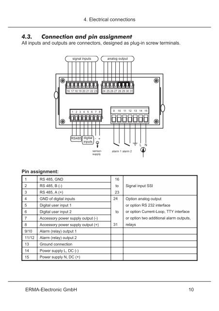
4.3. Connection and pin assignment<br />
All inputs and outputs are connectors, designed as plug-in screw terminals.<br />
Pin assignment:<br />
signal inputs analog output<br />
16 17 18 19 20 21 22 23 24 25 26 27 28 29 30 31<br />
1 2 3 4 5 6 7 8<br />
RS485<br />
4. Electrical connections<br />
digital<br />
inputs<br />
-<br />
+<br />
sensorsupply<br />
9 10 11 12 13 14 15<br />
alarm 1 alarm 2<br />
1 RS 485, GND 16<br />
2 RS 485, B (-) to Signal input SSI<br />
3 RS 485, A (+) 23<br />
4 GND of digital inputs 24 Option analog output<br />
5 Digital user input 1 or option RS 232 interface<br />
6 Digital user input 2 to or option Current-Loop, TTY interface<br />
7 Accessory power supply output (-) or option two additional alarm outputs,<br />
8 Accessory power supply output (+) 31 relays<br />
9/10 Alarm (relay) output 1<br />
11/12 Alarm (relay) output 2<br />
13 Ground connection<br />
14 Power supply L, DC (-)<br />
15 Power supply N, DC (+)<br />
E<strong>RMA</strong>-<strong>Electronic</strong> <strong>GmbH</strong> 10<br />
L N