System Overview Data - Douglas Lighting Control
System Overview Data - Douglas Lighting Control
System Overview Data - Douglas Lighting Control

You also want an ePaper? Increase the reach of your titles
YUMPU automatically turns print PDFs into web optimized ePapers that Google loves.
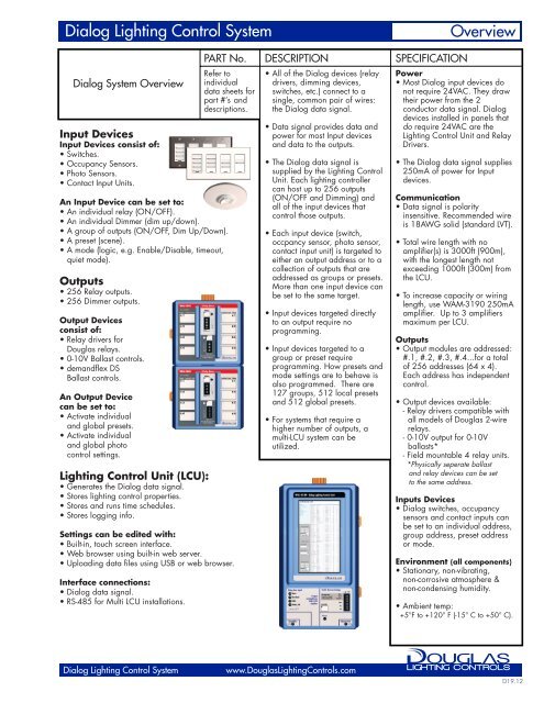
Dialog <strong>Lighting</strong> <strong>Control</strong> <strong>System</strong> <strong>Overview</strong><br />
Dialog <strong>System</strong> <strong>Overview</strong><br />
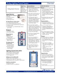
Input Devices<br />
Input Devices consist of:<br />
• Switches.<br />
• Occupancy Sensors.<br />
• Photo Sensors.<br />
• Contact Input Units.<br />
An Input Device can be set to:<br />
• An individual relay (ON/OFF).<br />
• An individual Dimmer (dim up/down).<br />
• A group of outputs (ON/OFF, Dim Up/Down).<br />
• A preset (scene).<br />
• A mode (logic, e.g. Enable/Disable, timeout,<br />
quiet mode).<br />
Outputs<br />
• 256 Relay outputs.<br />
• 256 Dimmer outputs.<br />
Output Devices<br />
consist of:<br />
• Relay drivers for<br />
<strong>Douglas</strong> relays.<br />
• 0-10V Ballast controls.<br />
• demandflex DS<br />
Ballast controls.<br />
An Output Device<br />
can be set to:<br />
• Activate individual<br />
and global presets.<br />
• Activate individual<br />
and global photo<br />
control settings.<br />
<strong>Lighting</strong> <strong>Control</strong> Unit (LCU):<br />
• Generates the Dialog data signal.<br />
• Stores lighting control properties.<br />
• Stores and runs time schedules.<br />
• Stores logging info.<br />
Settings can be edited with:<br />
• Built-in, touch screen interface.<br />
• Web browser using built-in web server.<br />
• Uploading data files using USB or web browser.<br />
Interface connections:<br />
• Dialog data signal.<br />
• RS-485 for Multi LCU installations.<br />
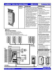
PART No. DESCRIPTION SPECIFICATION<br />
Refer to<br />
individual<br />
data sheets for<br />
part #’s and<br />
descriptions.<br />
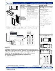
• All of the Dialog devices (relay<br />
drivers, dimming devices,<br />
switches, etc.) connect to a<br />
single, common pair of wires:<br />
the Dialog data signal.<br />
• <strong>Data</strong> signal provides data and<br />
power for most Input devices<br />
and data to the outputs.<br />
• The Dialog data signal is<br />
supplied by the <strong>Lighting</strong> <strong>Control</strong><br />
Unit. Each lighting controller<br />
can host up to 256 outputs<br />
(ON/OFF and Dimming) and<br />
all of the input devices that<br />
control those outputs.<br />
• Each input device (switch,<br />
occpancy sensor, photo sensor,<br />
contact input unit) is targeted to<br />
either an output address or to a<br />
collection of outputs that are<br />
addressed as groups or presets.<br />
More than one input device can<br />
be set to the same target.<br />
• Input devices targeted directly<br />
to an output require no<br />
programming.<br />
• Input devices targeted to a<br />
group or preset require<br />
programming. How presets and<br />
mode settings are to behave is<br />
also programmed. There are<br />
127 groups, 512 local presets<br />
and 512 global presets.<br />
• For systems that require a<br />
higher number of outputs, a<br />
multi-LCU system can be<br />
utilized.<br />
Dialog <strong>Lighting</strong> <strong>Control</strong> <strong>System</strong> www.<strong>Douglas</strong><strong>Lighting</strong><strong>Control</strong>s.com<br />
Power<br />
• Most Dialog input devices do<br />
not require 24VAC. They draw<br />
their power from the 2<br />
conductor data signal. Dialog<br />
devices installed in panels that<br />
do require 24VAC are the<br />
<strong>Lighting</strong> <strong>Control</strong> Unit and Relay<br />
Drivers.<br />
• The Dialog data signal supplies<br />
250mA of power for Input<br />
devices.<br />
Communication<br />
• <strong>Data</strong> signal is polarity<br />
insensitive. Recommended wire<br />
is 18AWG solid (standard LVT).<br />
• Total wire length with no<br />
amplifier(s) is 3000ft (900m),<br />
with the longest length not<br />
exceeding 1000ft (300m) from<br />
the LCU.<br />
• To increase capacity or wiring<br />
length, use WAM-3190 250mA<br />
amplifier. Up to 3 amplifiers<br />
maximum per LCU.<br />
Outputs<br />
• Output modules are addressed:<br />
#.1, #.2, #.3, #.4...for a total<br />
of 256 addresses (64 x 4).<br />
Each address has independent<br />
control.<br />
• Output devices available:<br />
- Relay drivers compatible with<br />
all models of <strong>Douglas</strong> 2-wire<br />
relays.<br />
- 0-10V output for 0-10V<br />
ballasts*<br />
- Field mountable 4 relay units.<br />
*Physically seperate ballast<br />
and relay devices can be set<br />
to the same address.<br />
Inputs Devices<br />
• Dialog switches, occupancy<br />
sensors and contact inputs can<br />
be set to an individual address,<br />
group address, preset address<br />
or mode.<br />
Environment (all components)<br />
• Stationary, non-vibrating,<br />
non-corrosive atmosphere &<br />
non-condensing humidity.<br />
• Ambient temp:<br />
+5°F to +120° F (-15° C to +50° C).<br />
D19.12
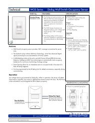
Dialog <strong>Lighting</strong> <strong>Control</strong> <strong>System</strong> Product Bulletin<br />
SYSTEM DESCRIPTION<br />
<strong>Lighting</strong> <strong>Control</strong> Unit (LCU)<br />
• The <strong>Lighting</strong> <strong>Control</strong> Unit (LCU) is the source of the Dialog signal.<br />
The Dialog signal combines the data signal and device power onto a single<br />
pair of wires (standard 18AWG solid is recommended).<br />
• Most input devices - Dialog switches, occupancy sensors and photo<br />
sensors - do not require any other connection than the Dialog signal.<br />
• Output devices also connect to the Dialog signal. Each output has a unique<br />
address and a maximum of 256 outputs can exist for each lighting controller.<br />
• The LCU stores all of the control settings such as control presets, time<br />
schedules, demand response settings, etc.<br />
• Changing the settings of the LCU is done via the built-in touch screen<br />
interface or via access to the LCU’s web server over TCP/IP connection.<br />
All Input Devices (Switches, Occupancy, Contact Input)<br />
• Can be assigned to a single address to control a single output (ON/OFF for<br />
relays, Dim UP/DOWN for dimmers).<br />
• Can be assigned to a group to control a collection of relays and dimmers<br />
(ON/OFF, Dim UP/DOWN).<br />
• Can be assigned to presets to either create a lighting scene or activate a<br />
mode.<br />
• There are 127 groups, 512 local presets, and 512 global presets.<br />
Photo Sensors<br />
• Can be assigned to 64 seperate local or global addresses.<br />
MODE functions (optional)<br />
• Up to 4 MODEs can be programmed for each group.<br />
Examples of MODE functions:<br />
1) Ignore occupancy sensors during the day, operate at night.<br />
2) Switches in public area don’t work during daytime, but do at night.<br />
3) Switches work normally during the day, but at night they operate in<br />
Timed-ON mode for automatic shut-off.<br />
Time Scheduler<br />
• Each LCU has a dedicated scheduler that can:<br />
1) Trigger and command individual addresses, group codes and preset<br />
addresses.<br />
2) Activate modes and photo controllers.<br />
<strong>Lighting</strong> <strong>Control</strong> Unit<br />
• Built-in touch screen interface.<br />
• Web browser utilizing built-in web server.<br />
• Uploading data files using USB or web.<br />
Dialog <strong>Lighting</strong> <strong>Control</strong> <strong>System</strong> www.<strong>Douglas</strong><strong>Lighting</strong><strong>Control</strong>s.com<br />
Web Browser<br />
Access<br />
RS-485 Bus<br />
<strong>Lighting</strong> <strong>Control</strong> Unit<br />
• 256 relays.<br />
• 256 dimmers.<br />
Networked LCUs<br />
• Standard RS-485 data signal.<br />
• Twisted pair, shielded cable.<br />
LCU-2<br />
LCU-3<br />
LCU-4<br />
LCU-1<br />
<strong>Data</strong><br />
Signal<br />
K24.11
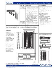
Product Bulletin<br />
Dialog Signal<br />
• Connect to all Output and Input devices.<br />
• Non-polarized, 2-conductor data and<br />
power cable.<br />
• 1000' longest length, 3000' total length.<br />
• Wiring is free topology.<br />
• Use amplifier for longer wire runs or for<br />
large amount of input devices.<br />
• Recommended wire: 2-conductor,<br />
18AWG, solid cable, no shield<br />
needed.<br />
Dialog Signal<br />
Classroom Example<br />
1 - General<br />
ON<br />
2 - All OFF<br />
Occupancy<br />
Sensor<br />
- all OFF<br />
when vacant<br />
Relay Panels<br />
cE c<br />
b b b<br />
a a a<br />
Photo Sensor<br />
- governs level for<br />
a & b lamps<br />
Dialog <strong>Lighting</strong> <strong>Control</strong> <strong>System</strong> www.<strong>Douglas</strong><strong>Lighting</strong><strong>Control</strong>s.com<br />
Dialog <strong>Lighting</strong> <strong>Control</strong> <strong>System</strong><br />
Amplifier<br />
(optional)<br />
Switches &<br />
Sensors<br />
cE c<br />
Window Window Window<br />
a<br />
1 - General<br />
ON<br />
2 - All OFF<br />
d<br />
d<br />
d<br />
a,b,c lamps ON/OFF<br />
dim lamps a,b,c<br />
d lamps ON/OFF<br />
quiet mode START/STOP<br />
K24.11
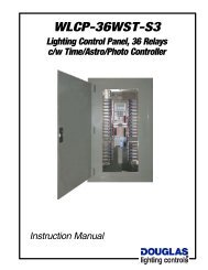
<strong>Overview</strong><br />
<strong>Data</strong> Signal<br />
The following table and diagram have been provided to demonstrate how the Dialog data<br />
signal is to be wired and how to calculate your wiring lengths and possible amplifier<br />
placements.<br />
Calculation method for DIALOG signal wire length<br />
Wire Gauge<br />
Maximum Wiring length<br />
(Max. distance from LCU<br />
or amplifier to device)<br />
16 AWG 500m<br />
18 AWG 300m<br />
The total wiring length should be a minimum<br />
of 3X the length of the longest wire<br />
Using 16 AWG wire, installation of an Amplifier can<br />
extend 500m max wiring length.<br />
When a maximum of 2 series wired amplifiers are<br />
used in a system, wiring can be extended to 1,500m<br />
total length maximum.<br />
Ampli�er<br />
Calcula�on method for DIALOG signal current<br />
Ex. 12 classrooms<br />
0-10V Ballast <strong>Control</strong>ler WDB-3314 4mAx12<br />
Relay Driver, 8 Outputs WRD-3408 3mAx12<br />
<strong>Data</strong> line Occupancy Sensor WOC-3801 3mAx12<br />
Photo sensors WPS-3711 3mAx12<br />
Dialog Signal 8- Bu�on Switch WSW-3508 3mAx12<br />
Dialog Signal Key Switch WSW-3502 3mAx12<br />
Total signal current consump�on 228 mA<br />
Ampli�er<br />
Ampli�er<br />
Ampli�er<br />
Ampli�er<br />
Ampli�er<br />
Maximum 5<br />
Ampli�ers<br />
in Star Wiring<br />
Dialog<br />
Devices<br />
Dialog <strong>Lighting</strong> <strong>Control</strong> <strong>System</strong> <strong>Overview</strong><br />
<strong>System</strong> Units Input Devices<br />
PART No. DESCRIPTION PART No. DESCRIPTION<br />
WLC-3150<br />
LCU<br />
<strong>Data</strong> Signal<br />
2 conductor<br />
Amplifier<br />
WAM-3190<br />
WIR-3110<br />
FREE topology<br />
Output Devices<br />
<strong>Lighting</strong> <strong>Control</strong> Unit<br />
• Stores and manages all system<br />
data and programming.<br />
• Supplies Dialog signal (400mA).<br />
• 256 relays.<br />
• 256 dimmers.<br />
• Connectivity to TCP/IP devices.<br />
Infrared Setting Unit<br />
• Set input devices target and<br />
address.<br />
• Set input devices properties.<br />
• Uses infrared.<br />
<strong>Data</strong> Signal<br />
• 2 conductor, 18AWG solid is<br />
recommended.Twisted or shielded<br />
cable is not necessary.<br />
• FREE topology wiring.<br />
• 3000ft (900m) total length,<br />
1000ft (300m) longest length.<br />
Use amplifier (WAM-3190) to<br />
boost.<br />
PART No. DESCRIPTION<br />
WRD-3408<br />
WDB-3314<br />
Relay Driver, 8 outputs,<br />
• Compatible with all <strong>Douglas</strong><br />
relays.<br />
• Connect to 24VAC & <strong>Data</strong> Signal.<br />
• Set address with DIP switches.<br />
• Adjacent units can plug into each<br />
other to minimize wiring.<br />
<strong>Data</strong> line 0-10V ballast<br />
controller, 4 outputs<br />
• 0-10V Dimming ballast module.<br />
• 4 Dimming address outputs.<br />
• Connect to 0-10V dimming<br />
ballasts (Maximum 50 ballasts<br />
per output).<br />
WPS-3711<br />
WOC-3801<br />
WCI-3928<br />
WSW-35xx Series<br />
WSD-<br />
3501<br />
WSW-<br />
3511<br />
WNxx Series<br />
Dialog <strong>Lighting</strong> <strong>Control</strong> <strong>System</strong> www.<strong>Douglas</strong><strong>Lighting</strong><strong>Control</strong>s.com<br />
WPS-3741<br />
WSK-<br />
3502<br />
WSW-<br />
3528<br />
Photo Sensors<br />
• Auto-ranging, 0 - 65,000 Lux<br />
• Set target with iR setting unit.<br />
WPS-3711 <strong>Data</strong> line photo sensor,<br />
interior ceiling, iR set<br />
WPS-3741 <strong>Data</strong> line photo sensor,<br />
exterior, iR set<br />
PIR, ceiling mount,<br />
Occupancy Sensor<br />
• Tilt and swivel lens.<br />
• Set target with iR setting unit.<br />
Contact Input, 8 inputs,<br />
c/w 24 VDC, 500 mA supply<br />
• 8 Contact Input Unit & 24VDC<br />
Power Supply.<br />
• Connect to 24VAC and data<br />
signal.<br />
• Configure for momentary or<br />
maintained contact signals.<br />
• Set target with iR setting unit.<br />
Wall Switches<br />
• Fits Standard Decora switch<br />
plates.<br />
• Status and locator LEDs.<br />
WSD-3501<br />
<strong>Data</strong> line dimmer and switch, 1ch.<br />
WSK-3502<br />
<strong>Data</strong> line keyswitch, c/w pilot light.<br />
WSW-3511<br />
<strong>Data</strong> line switch - 1 gang, 1 button<br />
(1x1), iR set.<br />
WSW-3512<br />
<strong>Data</strong> line switch - 1 gang, 2 buttons<br />
(1x2), iR set.<br />
WSW-3513<br />
<strong>Data</strong> line switch - 1 gang, 3 buttons<br />
(1x3), iR set.<br />
WSW-3514<br />
<strong>Data</strong> line switch - 1 gang, 4 buttons<br />
(1x4), iR set.<br />
WSW-3528<br />
<strong>Data</strong> line switch - 1 gang, 8 buttons<br />
(2x4), iR set.<br />
Cover Plates<br />
• WN-80301, 9, 11, 12, 21<br />
Sizes: 1 to 5 gang.<br />
Plastic cover plate.<br />
Invisible mounting screws.<br />
• WN-97401, 2, 3, 4, 5<br />
Sizes: 1 to 5 gang.<br />
Stainless steel cover.<br />
Visible mounting screws.<br />
K24.11