LCLS WBS Dictionary - Stanford Synchrotron Radiation Lightsource
LCLS WBS Dictionary - Stanford Synchrotron Radiation Lightsource
LCLS WBS Dictionary - Stanford Synchrotron Radiation Lightsource

Create successful ePaper yourself
Turn your PDF publications into a flip-book with our unique Google optimized e-Paper software.
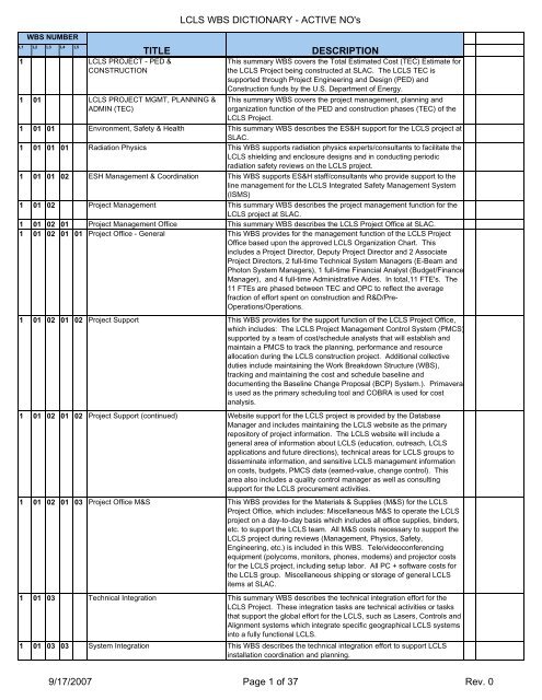
<strong>WBS</strong> NUMBER<br />
L1 L2 L3 L4 L5<br />
1 <strong>LCLS</strong> PROJECT - PED &<br />
CONSTRUCTION<br />
1 01 <strong>LCLS</strong> PROJECT MGMT, PLANNING &<br />
ADMIN (TEC)<br />
<strong>LCLS</strong> <strong>WBS</strong> DICTIONARY - ACTIVE NO's<br />
TITLE DESCRIPTION<br />
This summary <strong>WBS</strong> covers the Total Estimated Cost (TEC) Estimate for<br />
the <strong>LCLS</strong> Project being constructed at SLAC. The <strong>LCLS</strong> TEC is<br />
supported through Project Engineering and Design (PED) and<br />
Construction funds by the U.S. Department of Energy.<br />
This summary <strong>WBS</strong> covers the project management, planning and<br />
organization function of the PED and construction phases (TEC) of the<br />
<strong>LCLS</strong> Project.<br />
1 01 01 Environment, Safety & Health This summary <strong>WBS</strong> describes the ES&H support for the <strong>LCLS</strong> project at<br />
SLAC.<br />
1 01 01 01 <strong>Radiation</strong> Physics This <strong>WBS</strong> supports radiation physics experts/consultants to facilitate the<br />
<strong>LCLS</strong> shielding and enclosure designs and in conducting periodic<br />
radiation safety reviews on the <strong>LCLS</strong> project.<br />
1 01 01 02 ESH Management & Coordination This <strong>WBS</strong> supports ES&H staff/consultants who provide support to the<br />
line management for the <strong>LCLS</strong> Integrated Safety Management System<br />
(ISMS)<br />
1 01 02 Project Management This summary <strong>WBS</strong> describes the project management function for the<br />
<strong>LCLS</strong> project at SLAC.<br />
1 01 02 01 Project Management Office This summary <strong>WBS</strong> describes the <strong>LCLS</strong> Project Office at SLAC.<br />
1 01 02 01 01 Project Office - General This <strong>WBS</strong> provides for the management function of the <strong>LCLS</strong> Project<br />
Office based upon the approved <strong>LCLS</strong> Organization Chart. This<br />
includes a Project Director, Deputy Project Director and 2 Associate<br />
Project Directors, 2 full-time Technical System Managers (E-Beam and<br />
Photon System Managers), 1 full-time Financial Analyst (Budget/Finance<br />
Manager), and 4 full-time Administrative Aides. In total,11 FTE's. The<br />
11 FTEs are phased between TEC and OPC to reflect the average<br />
fraction of effort spent on construction and R&D/Pre-<br />
Operations/Operations.<br />
1 01 02 01 02 Project Support This <strong>WBS</strong> provides for the support function of the <strong>LCLS</strong> Project Office,<br />
which includes: The <strong>LCLS</strong> Project Management Control System (PMCS)<br />
supported by a team of cost/schedule analysts that will establish and<br />
maintain a PMCS to track the planning, performance and resource<br />
allocation during the <strong>LCLS</strong> construction project. Additional collective<br />
duties include maintaining the Work Breakdown Structure (<strong>WBS</strong>),<br />
tracking and maintaining the cost and schedule baseline and<br />
documenting the Baseline Change Proposal (BCP) System.). Primavera<br />
is used as the primary scheduling tool and COBRA is used for cost<br />
analysis.<br />
1 01 02 01 02 Project Support (continued) Website support for the <strong>LCLS</strong> project is provided by the Database<br />
Manager and includes maintaining the <strong>LCLS</strong> website as the primary<br />
repository of project information. The <strong>LCLS</strong> website will include a<br />
general area of information about <strong>LCLS</strong> (education, outreach, <strong>LCLS</strong><br />
applications and future directions), technical areas for <strong>LCLS</strong> groups to<br />
disseminate information, and sensitive <strong>LCLS</strong> management information<br />
on costs, budgets, PMCS data (earned-value, change control). This<br />
area also includes a quality control manager as well as consulting<br />
support for the <strong>LCLS</strong> procurement activities.<br />
1 01 02 01 03 Project Office M&S This <strong>WBS</strong> provides for the Materials & Supplies (M&S) for the <strong>LCLS</strong><br />
Project Office, which includes: Miscellaneous M&S to operate the <strong>LCLS</strong><br />
project on a day-to-day basis which includes all office supplies, binders,<br />
etc. to support the <strong>LCLS</strong> team. All M&S costs necessary to support the<br />
<strong>LCLS</strong> project during reviews (Management, Physics, Safety,<br />
Engineering, etc.) is included in this <strong>WBS</strong>. Tele/videoconferencing<br />
equipment (polycoms, monitors, phones, modems) and projector costs<br />
for the <strong>LCLS</strong> project, including setup labor. All PC + software costs for<br />
the <strong>LCLS</strong> group. Miscellaneous shipping or storage of general <strong>LCLS</strong><br />
items at SLAC.<br />
1 01 03 Technical Integration This summary <strong>WBS</strong> describes the technical integration effort for the<br />
<strong>LCLS</strong> Project. These integration tasks are technical activities or tasks<br />
that support the global effort for the <strong>LCLS</strong>, such as Lasers, Controls and<br />
Alignment systems which integrate specific geographical <strong>LCLS</strong> systems<br />
into a fully functional <strong>LCLS</strong>.<br />
1 01 03 03 System Integration This <strong>WBS</strong> describes the technical integration effort to support <strong>LCLS</strong><br />
installation coordination and planning.<br />
9/17/2007 Page 1 of 37 Rev. 0
<strong>WBS</strong> NUMBER<br />
L1 L2 L3 L4 L5<br />
<strong>LCLS</strong> <strong>WBS</strong> DICTIONARY - ACTIVE NO's<br />
TITLE DESCRIPTION<br />
1 01 03 05 Global Controls This is all non-recurring development for the first instance of each<br />
subsystem solution.<br />
1 01 03 05 05 Laser Heater Controls Development of the laser heater system.<br />
1 01 03 05 09 Power Supply Controls Development of the first power supply system.<br />
1 01 03 05 12 Global Controls Management Management support<br />
1 02 INJECTOR SYSTEM The injector generates the electron beam and accelerates it to 135 MeV.<br />
This system includes the laser, optical transport, the electron gun, the<br />
accelerator sections, the solenoids and other magnets, the diagnostics<br />
including a diagnostic section at the end of the injector, the <strong>LCLS</strong> timing<br />
system, and the laser room. The interface to the Linac is at the<br />
downstream end of Dog Leg 1 (DL1), ending at the valve at the entrance<br />
to linac section L1.<br />
1 02 02 Injector Controls Subsystem The injector controls system is to be an EPICS – Experimental Physics<br />
and Industrial Control System. The Injector control system must interface<br />
with the existing linear accelerator (LINAC) timing system. Local system<br />
control, at Sector 20, will be used for development through the<br />
commissioning phase of the project. Operational control will reside in the<br />
<strong>LCLS</strong> Main Control Center (MCC).<br />
1 02 02 13 Laser Heater Controls The laser heater controls system consists of control modules, cables and<br />
software to do on/off control of two laser shutters - one in beam<br />
conditioning optics, one at launch table. Steer the IR beam by controlling<br />
two motorized mirror stages on the launch table. Modifying the OTR<br />
control, if necessary, for the laser heater. Transmit the IR joulemeter<br />
signal from IR diagnostics to MCC. There are 4 analog signals which<br />
need to get to PEP via an ADC. There might be 0.5 months software<br />
work here, too. Transmit the IR timing diode signal to an oscilloscope<br />
near diagnostics port. Transmit the Spiricon camera image on the<br />
diagnostic table to MCC and receive controls from MCC. Transmit the<br />
electron beam energy spread data from OTR and to MCC. A PC might<br />
be needed here for the spectrometer. Reduce the data for the laser and<br />
the e-beam (the previous two items). Control the Undulator by stepping<br />
the motor and reading the position from LVDT sensors and the limit<br />
switches.<br />
1 02 03 Injector Lasers The drive laser system provides ultraviolet (UV) irradiation to the cathode<br />
of the <strong>LCLS</strong> RF photoinjector. The drive laser utilizes a standard chirped<br />
pulse amplification (CPA) design beginning with a mode-locked infrared<br />
(ir) oscillator. Oscillator pulses are temporally shaped and stretched<br />
before entering the IR amplifier chain. This chain amplifies the single<br />
pulse energy in two sections (i) the preamplifier and (ii) the final amplifier.<br />
Ir pulse energies of order 10’s of millijoules are obtained during the final<br />
amplification where the repetition rate is also reduced to 120 Hz, the RF<br />
photoinjector design repetition rate. Following amplification and repetition<br />
rate reduction, a portion of the IR pulse energy is converted to UV<br />
irradiation via third harmonic generation in nonlinear media. UV pulse<br />
energies of a few millijoules are generated, conditioned, and transported<br />
to the photocathode.<br />
1 02 03 03 Drive Laser Diagnostics The drive laser diagnostics includes several diagnostics clusters for<br />
each stage of the system: oscillator, preamplifier, final amplifier and UV<br />
conversion. Special ultra-fast high resolution diagnostics for the<br />
waveform (temporal shape) measurements will be designed by LLNL.<br />
The oscillator diagnostic cluster is intended to monitor the intrinsic<br />
oscillator output as well as the results of temporal pulse shaping and<br />
stretching. The diagnostic cluster includes a spatial profile imaging<br />
system, a fast photodiode, an average power sensor, a time-integrated<br />
spectrometer for monitoring bandwidth as well as mode-locked<br />
operation, and broadband time-resolved diagnostics for monitoring<br />
temporal pulse-width and shape (using techniques such as scanning<br />
autocorrelation and frequency-resolved optical-gating (FROG)<br />
detection). Where possible, diagnostics require only a sample of the<br />
oscillator pulse energy.<br />
9/17/2007 Page 2 of 37 Rev. 0
<strong>WBS</strong> NUMBER<br />
L1 L2 L3 L4 L5<br />
<strong>LCLS</strong> <strong>WBS</strong> DICTIONARY - ACTIVE NO's<br />
TITLE DESCRIPTION<br />
1 02 03 03 Drive Laser Diagnostics (Continued) The preamplifier diagnostic cluster is intended to monitor the preamplifier<br />
output. It includes fast photodiode detection, a pulse energy/power<br />
meter, spatial profile imaging, and broadband single pulse detection (as<br />
would be provided, for example, by polarization-gated frequencyresolved<br />
optical-gating detection (PG-FROG)). This single pulse<br />
broadband time-resolved detection monitors the temporal pulse shape<br />
(envelope) that is established between the preamplifier and the oscillator.<br />
1 02 03 03 Drive Laser Diagnostics (Continued) Final amplifier diagnostics is used to monitor the final amplifier output<br />
prior to UV conversion. It includes fast diode detection, a time-integrating<br />
spectrometer, spatial profile imaging, energy/power sensors, and<br />
broadband time-resolved single pulse diagnostics, with potential to add a<br />
single-pass oscillator probe beam. As with the preamplifier, single pulse<br />
broadband detection is used to monitor the established temporal pulse<br />
shape (envelope) with all amplifier effects included.<br />
1 02 03 03 Drive Laser Diagnostics (Continued) The UV diagnostic cluster is located at the harmonic generation unit and<br />
monitors the UV pulse features prior to transport to the photocathode in<br />
the tunnel. It includes a fast photodiode, a pulse energy/power monitor,<br />
a time-integrated spectrometer, spatial profile imaging, and single pulse<br />
broadband time-resolved UV pulse detection (which will include a streak<br />
camera).<br />
1 02 17 Injector System Installation System Summary for installation of beamline components, controls<br />
hardware and cabling.<br />
1 02 17 15 Laser Heater Installation This section accounts for the specific tasks associated with the field<br />
installation of the specific Injector section.<br />
1 03 LINAC SYSTEM The Linac accelerates the electron beam while preserving the transverse<br />
emittance and compressing the longitudinal size. This element includes<br />
modifications to the last third of the existing SLAC linac, Bunch<br />
Compressor 1 (BC1), Bunch Compressor 2 (BC2), beam transport to the<br />
Undulator (LTU), beam transport after the undulator, bend magnets and<br />
beam dump, the bypass system for transporting test beams to end<br />
station A, and diagnostics including characterizing both the electron and<br />
x-ray beams as they pass through the undulator. The interface with the<br />
undulator is a vacuum flange at each end of the undulator. This element<br />
includes the common beam line beyond the undulator for the electrons<br />
and x-rays until the electrons are deflected enough for an interface to the<br />
x-ray beam line.<br />
1 03 01 System Management & Integration The Linac is made up of a number of individual devices and systems.<br />
These devices and systems must be integrated into functional blocks. In<br />
consecutive order with respect to the electron beam the functional blocks<br />
or areas are: Linac 1 (L01), Bunch Compressor Chicane 1 (BC1), Linac<br />
2 (L02), Bunch Compressor Chicane 2 (BC2), Linac 3 (L03), Linac-to-<br />
Undulator Transport Line (LTU), and Main Electron Dump (E-Dump).<br />
1 03 01 01 Linac Mechanical Integration Linac Mechanical Integration defines a physical envelope for the <strong>LCLS</strong><br />
modifications in the Accelerator Housing and Klystron Gallery.<br />
Mechanical Integration also ensures that existing Linac systems are,<br />
once modified by <strong>LCLS</strong>, returned to an acceptable level of function along<br />
with complete documentation.<br />
1 03 01 01 04 BC2 System Integration BC2 applies second stage bunch compression to the electron beam.<br />
Representing an <strong>LCLS</strong> Linac functional block, it is here where the<br />
functional requirements for systems and components are presented,<br />
reviewed, and documented. The mechanical top assembly of this<br />
functional area is completed here.<br />
1 03 01 01 05 L03 System Integration L3 accelerates the electron beam to a final energy of 14 Gev.<br />
Representing an <strong>LCLS</strong> Linac functional block, it is here where the<br />
functional requirements for systems and components are presented,<br />
reviewed, and documented. The mechanical top assembly of this<br />
functional area is completed here.<br />
9/17/2007 Page 3 of 37 Rev. 0
<strong>WBS</strong> NUMBER<br />
L1 L2 L3 L4 L5<br />
<strong>LCLS</strong> <strong>WBS</strong> DICTIONARY - ACTIVE NO's<br />
TITLE DESCRIPTION<br />
1 03 01 01 06 LTU System Integration LTU transports the electron beam to the FEL Undulator. The system<br />
includes bend magnets that support energy and emittance diagnostics.<br />
Representing an <strong>LCLS</strong> Linac functional block, it is here where the<br />
functional requirements for systems and components are presented,<br />
reviewed, and documented. The mechanical top assembly of this<br />
functional area is completed here<br />
1 03 01 01 07 E-Dump System Integration The Electron Dump receives the electron beam from the FEL Undulator<br />
and terminates the electron stream. It is a high radiation area with<br />
possibly some beam diagnostic capabilities. Representing an <strong>LCLS</strong><br />
Linac functional block, it is here where the functional requirements for<br />
systems and components are presented, reviewed, and documented.<br />
The mechanical top assembly of this functional area is completed here<br />
1 03 01 03 Travel Linac group project-related travel expenditures.<br />
1 03 01 04 Linac Management Linac group costs related to management; administration, personal<br />
computers, productivity software, as well as simulation and modeling<br />
software.<br />
1 03 02 Linac Controls & Power Conversion Provide an EPICS based control system for the portions of the linac that<br />
Subsystem<br />
are modified for <strong>LCLS</strong> use.<br />
1 03 02 01 Personnel Protection System (PPS) This system creates a physical barrier that subtends the <strong>LCLS</strong> for the<br />
purpose of personnel protection from radiation, electrical, and other<br />
present or imagined hazards. An <strong>LCLS</strong> area may use or combine with<br />
other SLAC control areas. The PPS system will include monitoring of<br />
radiation shielding integrity, barriers, area status annunciators, and<br />
multiple interlocked control gates for access to a safe machine space.<br />
1 03 02 02 Beam Containment System (BCS) The BCS includes components like stoppers and dumps that along with<br />
shielding provide a safe way to contain radiation that is generated under<br />
all <strong>LCLS</strong> operating conditions. This system also includes active<br />
instruments (beam shut off ion chambers - BSOIC’s) that will disable<br />
operations if elevated levels of radiation (Neutron & Gamma) are<br />
detected outside of the PPS control area.<br />
1 03 02 03 Machine Protection System (MPS) This is a system of sensors (i.e. water flow switches, thermocouples)<br />
supplied as Digital and/or Analog signals which are interlocked, that will<br />
in turn shut off the beam if conditions exist/persist that will cause<br />
damage to machine hardware or other protection systems.<br />
1 03 02 04 Linac Power Conversion Subsystem The power supplies for the <strong>LCLS</strong> Linac will, for the most part, be a<br />
standard design and are used throughout the SLAC accelerator. This<br />
Linac <strong>WBS</strong> Power Supply subsystem has been divided into three types,<br />
Dipole, Quadruple and Trim and are described below. The <strong>WBS</strong> unit will<br />
not provide for Fabrication or Installation activities. In addition, the design<br />
of the magnet power supply systems assumes that all magnets will have<br />
their magnet electrical connections covered such that the powered<br />
systems comply with SLAC, National Electric Code and OSHA<br />
regulations. There is no provision for interlocking the magnet power<br />
supplies for magnet safety.<br />
1 03 02 04 01 Beamline Power Supplies - (Dipole Type) The Dipole Power Supplies provide power to dipole magnets. These<br />
units cover the LINAC, BSY and the LTU. There are 7 units, which are:<br />
BXH11-14, BXH 21-26, BXH 31-34, BY1, KICKER (BYBKIK), BYW, and<br />
the Dump Bend.<br />
1 03 02 04 02 Beamline Power Supplies - (Quad Type) The Quadruple Section power supplies power quadruple magnets which<br />
provide power to the focusing elements in the transport system. This<br />
section has the largest number of units and there will be 31 units which<br />
are: SEC-23 (2KW), SEC-24(2KW), SEC-25 (2KW), SEC-26 (2KW),<br />
SEC-27 (2KW), SEC-28 (2KW), SEC-29 (2KW), Q24701, QM21,<br />
Q24901, QM22, QVM1, QVM2, QVM3, QVM4, QVB1, QDL1, QE31,<br />
QEM1, QEM2, QEM3, QEM4, Qtm1, Qtm2, QUM1, QUM2, QUM3,<br />
QUM4, QDMP, QUE1 and QUE2.<br />
1 03 02 04 03 Beamline Power Supplies - (Trim Type) The last type is the Trim Type and these power supplies power magnets<br />
that operate at low currents and make minor orbit corrections to the<br />
beam. There will be 10 new units, which are: MCOR_1, MCOR_2,<br />
MCOR_3, MCOR_4, MCOR_LTU1, MCOR_LTU2, MCOR_LTU3,<br />
MCOR_LTU4, MCOR_LTU5, MCOR_LTU6.<br />
9/17/2007 Page 4 of 37 Rev. 0
<strong>WBS</strong> NUMBER<br />
L1 L2 L3 L4 L5<br />
<strong>LCLS</strong> <strong>WBS</strong> DICTIONARY - ACTIVE NO's<br />
TITLE DESCRIPTION<br />
1 03 02 04 04 Controls & Power Supply This section covers the costs associated with the packaging (integration<br />
of systems equipment) and testing of electrical equipment racks for the<br />
Power Conversion and Control Systems. Rack infrastructure i.e. AC<br />
power distribution, plugstrips, utility outlets, cooling fans and mounting<br />
brackets are integrated prior to the integration of previously procured<br />
rack and crate mounted equipment from the various sections. Cableplant<br />
installation design of Trays and Long-Haul cables (Using CAPTAR<br />
database) to be installed into the various areas, resulting in an award of<br />
contract, takes place here.<br />
1 03 02 05 Controls - LLRF LLRF is a system for the amplitude and phase control of the electron<br />
beam. It includes a new master oscillator and the distribution of the 2856<br />
MHz RF and the machine timing signals. It also includes the RF control<br />
system around individual klystrons for stabilizing (low noise, low drift)<br />
and monitoring of their operation. A preponderance of design and<br />
procurement resides within the RF Section budget leaving controls with a<br />
engineering supporting role. This equipment also provides the means of<br />
avoiding Main Drive Line phase jumps when operating PEPII.<br />
1 03 02 06 Controls - E-Beam Diagnostic Diagnostic devices measure salient beam parameters such as beam<br />
size, position, phase, bunch length, beam current etc. for the purposes of<br />
setting and tuning the various machine parameters such as the strength<br />
of magnets and the amplitude and phase of klystrons. The diagnostic<br />
signals provide a monitoring function and in some case a direct feedback<br />
for closed-loop control of the accelerator hardware.<br />
1 03 02 06 01 Controls - Wire Scanners Wire scanners are beam profile monitors used to provide accurate<br />
measurements of beam size and position in all three planes (vertical,<br />
horizontal and 45 degrees) for beam measurement systems and beam<br />
tuning procedures. Components include wires capable of being moved<br />
precisely through the path of a beam, and a detector which can<br />
accurately measure the amount of charge striking a wire. When in use, a<br />
wire is scanned across the path of a beam using stepper motors, and a<br />
plot of wire position versus beam intensity is generated that represents<br />
the beam profile.<br />
1 03 02 06 02 Controls - BPMs Beam Position Monitor. A device including four electrodes located inside<br />
the beam pipe, and the associated electronics necessary to locate the<br />
position of the centroid of the beam. The electrodes are usually located<br />
about 90 degrees apart inside the vacuum chamber, far enough away<br />
from the beam's path not to interfere with it, but close enough to feel the<br />
electric charge of the beam's passing. A device called an RF cavity BPM<br />
uses resonant cavities in place of electrodes to detect the electric charge<br />
of the beam.<br />
1 03 02 06 03 Controls - Toroids The Toroid is an average beam current (charge) monitor (CM) which<br />
uses transformer action to measure the intensity of a beam pulse. A lead<br />
shielded pre-amplifier is usually placed near and connected to the wire<br />
wound ferrites. The amplified signal is then cabled to an electronic<br />
module external to the shielded housing. Comparisons can be made<br />
between Toroid installations as a way of determining beam losses<br />
between two points.<br />
1 03 02 06 04 Controls - Stoppers A Personnel Protection System device used to stop the beam, usually by<br />
allowing a heavy metal slug to pivot into the beam's path. The deenergized<br />
default is in the beam path as a fail-safe. This is removed from<br />
the path by means of air solenoids. This device, as all PPS devices rely<br />
on redundant parallel limit switches to supply status prior to allowing<br />
entry into beamline areas.<br />
9/17/2007 Page 5 of 37 Rev. 0
<strong>WBS</strong> NUMBER<br />
L1 L2 L3 L4 L5<br />
<strong>LCLS</strong> <strong>WBS</strong> DICTIONARY - ACTIVE NO's<br />
TITLE DESCRIPTION<br />
1 03 02 06 05 Controls - Profile Monitors A screen inserted is inserted into a beam transport line to view the beam<br />
cross section via a remote camera focused through a glass viewing port.<br />
The screen can be made from a variety of materials suited to the beam<br />
energy at that location. The visible emission picture is captured on a<br />
digital video camera, triggered to look a specific beam pulse. Profile<br />
monitor screens can be inserted and removed remotely by the machine<br />
operators. Position status is determined by limit switches. Cameras can<br />
be remotely triggered, iris controlled, zoom activated, lamp intensity<br />
varied via electronic modules connected to a two channel Profile Monitor<br />
chassis.<br />
1 03 02 06 07 Controls - Bunch Length Monitors The bunch length monitor, BLM, is used to measure the length of the<br />
bunch after each longitudinal compression stage in the accelerator. The<br />
measurement is done on a pulse-by-pulse basis so that the information<br />
can be transmitted to a feedback loop for control and stabilization of the<br />
bunch length. The BLM device senses the coherent radiation from the<br />
bunch, where the spectral power is proportional to the peak current in the<br />
bunch and so is able to detect relative changes in bunch length. For<br />
calibration purposes this measurement is compared to measurements<br />
made with the RF transverse deflecting cavities.<br />
1 03 02 06 09 Controls - Single Beam Dump The single bunch beam dumper, SBBD, consists of a fast-acting pulsed<br />
magnet that is able to selectively deflect a bunch toward a beam stopper<br />
on a pulse-by-pulse basis. The purpose of this is to control the rate at<br />
which beam is sent to the downstream undulator beam line which<br />
contains sensitive equipment. If a fault condition occurs such as a beam<br />
loss in the undulator then the SBBD is able to prevent the next beam<br />
pulse from being sent down the beam line and potentially causing<br />
damage. The fault conditions are passed to the SBBD from the Machine<br />
Protection System, MPS. The SBBD is able to stop the full-rate 120 Hz<br />
beam from the linac upstream and selectively allow single shots, 1 Hz,<br />
10 Hz or an arbitrary rate to be sent downstream, thereby facilitating tune<br />
up of the beam without risking damage to the beam line.<br />
1 03 02 06 12 Controls - Movable Collimator This system provides control and monitoring of two-axis beam<br />
intercepting blades which can be used as a diagnostic in the LTU front<br />
end and further downstream for beam clean-up. Stepper-motors are<br />
used for movement which is read back with transducers (LVDT’s) for<br />
positional information.<br />
1 03 02 08 Controls - Timing This system includes the synchronization of pulsed accelerator devices<br />
with generating the beam and the acquisition of beam measurements for<br />
use in feedback and timing.<br />
1 03 02 09 Controls - Vacuum This system includes the monitoring and control of gages, pumps, and<br />
valves. This system includes interlocks for the protection of the machine<br />
during maintenance and against a catastrophic change in pressure.<br />
1 03 02 09 01 Controls - Vacuum Instrumentation &<br />
Interlocks<br />
This system collects and displays the operating state of vacuum system<br />
in discrete areas of the accelerator. It uses this information to control<br />
beam operation as well as the state of isolation valves and vacuum<br />
pump power supplies.<br />
1 03 02 10 Software & Controls Infrastructure The controls infrastructure provides the interconnection between various<br />
parts of the control system. It performs supervisory function for the<br />
control network. It includes the software tools and applications for the<br />
real time programming of the control modules as well as the tools for<br />
supporting the database structure.<br />
1 03 02 10 04 Data Communications Gigabit networking has been costed to connect 5 locations to MCC. The<br />
locations are: Bldg 406, sector 24, sector 30, support bldg at near end<br />
and the end of the LTU. One gigabit switch has been allocated per<br />
location except at the end station, where two have been allocated<br />
because of the high quantity of cameras at this location. Wireless<br />
network access points (to the visitor network) are also included.<br />
9/17/2007 Page 6 of 37 Rev. 0
<strong>WBS</strong> NUMBER<br />
L1 L2 L3 L4 L5<br />
<strong>LCLS</strong> <strong>WBS</strong> DICTIONARY - ACTIVE NO's<br />
TITLE DESCRIPTION<br />
1 03 02 10 05 Computers This is actually "Computers and crates". VME crates with Power PC<br />
controllers and VxWorks run-time licenses have been costed for all<br />
systems. The cables and the modules that go in the crates are<br />
distributed across the systems (in the rest of the controls <strong>WBS</strong>) that<br />
use/need them. No workstations have been costed for the Linac<br />
controls.<br />
1 03 03 Linac Magnets & Supports This system may include permanent and electromagnetic elements<br />
(dipoles, quadrupoles, sextupoles, and correctors) for the manipulation<br />
and direction of charged beams. The structure and systems to locate<br />
and accurately position these elements are included in the system.<br />
1 03 03 02 Bend Magnet (BX3_LTU) This is an existing bend magnet design for use in the LTU. Five existing<br />
bend magnets will be recycled from SLAC / FFTB. One of the five will<br />
become the first bend in the dump line in front of the BYD bend magnets.<br />
1 03 03 03 Bend Magnet (BX2_BC2) This is a new bend magnet design for use in BC1. It is direct current<br />
string of four magnets powered to bend the electron beam into and out of<br />
the BC2 chicane. The final alignment stage for each magnet and support<br />
stand for the entire BC2 system have been cost with these components.<br />
1 03 03 04 Bend Magnet (BY_LTU) This is a new bend magnet design for use in the LTU. It is a direct<br />
current powered to bend the electron beam in a vertical plane in the LTU.<br />
1 03 03 05 Quad Magnet (Quad_LTU) These magnets are an existing design. Fifteen additional units will have<br />
to be fabricated to augment the lot of existing refurbished units that will<br />
be removed from FFTB.<br />
1 03 03 08 Corrector Magnet (Type 4) This is an existing linac design for a weak (iron core) bend magnet. Its<br />
large appeture allows for installation over the accelerating structure.<br />
They provide bend correction for the electron beam. A single design can<br />
be installed in either a vertical or horizontal orientation. The majority of<br />
these magnetic elements exists in the current linac and will assume new<br />
position and control for <strong>LCLS</strong>.<br />
1 03 03 09 Bend Magnet (BYD_DUMP) This is a new direct current electromagnetic dipole that bends the bends<br />
the spent electron beam after the Undulator and directs it to the main<br />
dump. Along with other magnetic elements, this magnet is part of a<br />
spectrometer that analyzes the energy distribution of the discarded<br />
electrons that reach the dump.<br />
1 03 03 10 Quad Magnet (QA) This is an existing linac Quadrupole magnet for focusing or defocusing of<br />
the electron beam. They are usually found at linac intergirder and or drift<br />
locations. The majority of these magnetic elements already exists in the<br />
current linac and will assume new position and control for <strong>LCLS</strong>.<br />
1 03 03 11 Bend Magnet (BYPM_LTU) This is a new system of permanent dipole magnets located immediately<br />
after the dump bend magnet that directs the electron beam into a safe<br />
shielding zone in the event of a failure of the Dump Bend Magnet.<br />
1 03 03 12 Bend Magnet (BYKIK_LTU) This is a new pulsed magnet in the LTU that limits the rate of beam<br />
bunches into the Undulator by deflecting unwanted bunches out of the<br />
forward Beamline into the Single Beam Dump.<br />
1 03 03 14 BXKIK LINAC TCAV Screen Kicker This <strong>WBS</strong> section identifies and collects the resources and costs<br />
associated with the BXKIK LINAC TCAV Screen Kicker.<br />
1 03 04 Linac Vacuum Subsystem Section Summary<br />
1 03 04 02 Linac Beamline Vacuum System This section represents all of the interconnecting vacuum parts between<br />
accelerating, magnetic, or diagnostic components for the identified <strong>LCLS</strong><br />
system. It includes, but is not limited too, drifts, tees, pumps, gauges,<br />
pumps, and manifolds. Gauge controllers and ion pump controllers are<br />
not included in this section. They are estimated under <strong>WBS</strong> 1.3.2.9.<br />
Cutting and re-assembly of accelerator structures are not covered under<br />
this <strong>WBS</strong> number. Those activities are covered under <strong>WBS</strong> 1.3.6.2.<br />
9/17/2007 Page 7 of 37 Rev. 0
<strong>WBS</strong> NUMBER<br />
L1 L2 L3 L4 L5<br />
<strong>LCLS</strong> <strong>WBS</strong> DICTIONARY - ACTIVE NO's<br />
TITLE DESCRIPTION<br />
1 03 04 04 BC2 Vacuum System This section represents all of the interconnecting vacuum parts between<br />
accelerating, magnetic, or diagnostic components for the identified <strong>LCLS</strong><br />
system. It includes, but is not limited to, drifts, tees, pumps, gauges,<br />
pumps, and manifolds. Gauge controllers and ion pump controllers are<br />
not included in this section. They are estimated under <strong>WBS</strong> 1.3.2.9.<br />
Since the vacuum supports are an integral part of the BC2 magnet<br />
support system those items are covered under <strong>WBS</strong> 1.3.3.3.<br />
1 03 04 05 Linac to Undulator (LTU) Vacuum System This section represents all of the interconnecting vacuum parts between<br />
accelerating, magnetic, or diagnostic components for the identified <strong>LCLS</strong><br />
system. It includes, but is not limited to, drifts, tees, pumps, gauges,<br />
pumps, vacuum supports and manifolds. Gauge controllers and ion<br />
pump controllers are not included in this section. They are estimated<br />
under <strong>WBS</strong> 1.3.2.9<br />
1 03 04 06 Dumpline Vacuum System This section represents all of the interconnecting vacuum parts between<br />
accelerating, magnetic, or diagnostic components for the identified <strong>LCLS</strong><br />
system. It includes, but is not limited to, drifts, tees, pumps, gauges,<br />
pumps, vacuum supports and manifolds. Gauge controllers and ion<br />
pump controllers are not included in this section. They are estimated<br />
under <strong>WBS</strong> 1.3.2.9<br />
1 03 04 07 Vacuum System Undulator Interface Specification of the vacuum system requirements at the entrance and<br />
exit to the undulator system.<br />
1 03 04 07 01 Entrance Section Assembly Specification of the vacuum system requirements at the entrance to the<br />
undulator system.<br />
1 03 04 07 02 Exit Section Assembly Specification of the vacuum system requirements at the exit to the<br />
undulator system.<br />
1 03 04 08 LTU/BSY& Cold Trap Vacuum System This section represents all of the interconnecting vacuum parts between<br />
accelerating, magnetic, or diagnostic components for the identified <strong>LCLS</strong><br />
system. It includes, but is not limited to, drifts, tees, pumps, gauges,<br />
pumps, vacuum supports and manifolds. Gauge controllers and ion<br />
pump controllers are not included in this section. They are estimated<br />
under <strong>WBS</strong> 1.3.2.9<br />
1 03 05 Linac Electron Diagnostics Summary System Summary<br />
1 03 05 01 Wire Scanners (7) Summary Wire Scanners are used to measure beam size in order to determine<br />
Beam Emittance and Energy Spread. They consist of at least one set of<br />
wires orthogonal to the beam Z-axis that are moved through the electron<br />
beam. The resulting radiation is measured by a photon detector.<br />
1 03 05 02 Beam Position Monitors Beam Position Monitors (BPM) identify the local position of the electron<br />
beam relative to a known mechanical and magnetic reference<br />
(quadrupole magnet magnetic center relative to physical references).<br />
The <strong>LCLS</strong> linac has two BPM design types; electrode and RF. The<br />
stripline electrode BPM generates a signal proportional to the<br />
dimensional offset between the electron bunch center and the BPM<br />
center. The RF BPM is an RF resonant cavity that measures the bunch<br />
position based on the amplitude and phase shift of the RF pulse<br />
proportional to the electron bunch. BPM and magnet data can be used to<br />
automatically tune the electron beam position.<br />
1 03 05 02 03 BPM - FFTB (12) Summary This electrode type FFTB BPM is an established design. Existing units in<br />
the SLAC FFTB will be refurbished and used in the LTU. The balance of<br />
the required FFTB type BPMs (~30%) will be a revised design modeled<br />
on the historical design.<br />
1 03 05 03 Toroid Beam Current Monitor (10)<br />
Summary<br />
Toroids measure both discrete local and integrated system level electron<br />
beam current. As a local device, a Toroid measures beam current by<br />
producing a signal proportional to the electron bunch current.<br />
Measurements by two or more Toroids in a system can be made to<br />
indicate average current per bunch. A system of Toroids can also be<br />
used to indicate beam losses by comparing bunch current at multiple<br />
locations.<br />
9/17/2007 Page 8 of 37 Rev. 0
<strong>WBS</strong> NUMBER<br />
L1 L2 L3 L4 L5<br />
<strong>LCLS</strong> <strong>WBS</strong> DICTIONARY - ACTIVE NO's<br />
TITLE DESCRIPTION<br />
1 03 05 04 Beam Stoppers (4) Summary Beam stoppers are water cooled diagnostic/protection devices that are<br />
inserted into the electron path to stop the beam. They are designed to<br />
absorb the electron beam power. Beam stoppers may be designed for a<br />
reduced electron bunch rate to minimize heat load and radiation effects.<br />
Stoppers are placed in the beam path to tune the upbeam electron beam<br />
path while the stopper is protecting personnel and downbeam radiation<br />
sensitive devices.<br />
1 03 05 05 Profile Monitors (7 OTR-3 PHOSPHOR<br />
SCREEN-1 YAG)<br />
1 03 05 07 CSR/OTR/CTR Bunch Length Monitors<br />
(5) Summary<br />
Profile monitors are beam emittance and energy spread diagnostic<br />
devices. They characterize beam shape, size, and position. Profile<br />
monitor designs consist of a fluorescent screen or metal foil that<br />
interacts with the electron beam and produces secondary radiation that<br />
is monitored by detectors and/ or cameras.<br />
This device generates a signal proportional to the bunch length by<br />
measuring terahertz and synchrotron radiation produced as the electron<br />
beam passes through a thin foil.<br />
1 03 05 09 Single Beam Dump (1) Summary The single beam dump is an electron beam stopper designed to absorb<br />
the full beam energy. This dump is designed for system tuning and to<br />
provide protection for the undulator system in concert with a pulsed bend<br />
magnet.<br />
1 03 05 10 Electron Beam Dump (1) Summary The electron beam dump is the endpoint for the electron beam in the<br />
<strong>LCLS</strong> system after the beam passes through the undulator system.<br />
1 03 05 11 Protection Collimators (5) Summary Protection collimators are designed to limit the beam cross sectional<br />
dimensions in X and Y to prevent damage to devices downbeam from<br />
the collimator.<br />
1 03 05 12 Movable Collimators (7x,3y) Summary Movable collimators are designed to tune the electron beam<br />
characteristics by limiting the beam dimension in either the X or Y axes.<br />
1 03 05 13 Safety Electron Dump (1) Summary The safety electron dump is a redundant system designed to remove the<br />
electron beam in the event of a system failure mode.<br />
1 03 07 Linac Installation & Alignment This <strong>WBS</strong> section covers the reception of parts, components, and sub<br />
assemblies from either a Post Processing & Testing or a Rack<br />
Integration activity. Installation begins at beneficial occupancy or at a<br />
planned SLAC Linac downtime and completes all necessary activities<br />
prior to the start of commissioning. These activities are, but not limited<br />
to, mechanical installation of beam line components, installation of<br />
vacuum components, alignment, vacuum pump down, vacuum leak<br />
checking and functional testing of components and all of their respective<br />
control systems. Management of project installation activities are not<br />
covered in this section. Those activities are covered under <strong>WBS</strong> 1.3.1,<br />
System Management & Integration. This <strong>WBS</strong> section also covers the<br />
removal and/or relocation of existing SLAC Linac beam line components<br />
to make room for new <strong>LCLS</strong> Linac components such as magnets,<br />
vacuum components, RF components and diagnostic instruments.<br />
1 03 07 03 Linac L02 System Installation & Alignment This <strong>WBS</strong> section identifies and collects the resources and costs<br />
associated with the removal and/or relocation of SLAC Linac beam line<br />
components and the installation of all <strong>LCLS</strong> Linac beam line components<br />
in accordance with the activity description above.<br />
1 03 07 04 Linac BC2 System Installation &<br />
Alignment<br />
This <strong>WBS</strong> section identifies and collects the resources and costs<br />
associated with the removal of SLAC Linac beam line components and<br />
the installation of all BC2 components in accordance with the activity<br />
description above.<br />
1 03 07 05 Linac L03 System Installation & Alignment This <strong>WBS</strong> section identifies and collects the resources and costs<br />
associated with the removal and/or relocation of SLAC Linac beam line<br />
components and the installation of all <strong>LCLS</strong> Linac beam line components<br />
in accordance with the activity description above.<br />
1 03 07 06 Linac LTU System Installation &<br />
Alignment<br />
This <strong>WBS</strong> section identifies and collects the resources and costs<br />
associated with the removal and/or relocation of SLAC FFTB beam line<br />
components and the installation of all <strong>LCLS</strong> Linac beam line components<br />
in accordance with the activity description above.<br />
9/17/2007 Page 9 of 37 Rev. 0
<strong>WBS</strong> NUMBER<br />
L1 L2 L3 L4 L5<br />
1 03 07 07 Linac E-Dump System Installation &<br />
Alignment<br />
<strong>LCLS</strong> <strong>WBS</strong> DICTIONARY - ACTIVE NO's<br />
TITLE DESCRIPTION<br />
This <strong>WBS</strong> section identifies and collects the resources and costs<br />
associated with the removal and/or relocation of SLAC FFTB beam line<br />
components and the installation of all <strong>LCLS</strong> Linac beam line components<br />
in accordance with the activity description above.<br />
1 03 07 20 LINAC Installation 2007 Shut Down This <strong>WBS</strong> section covers the FY2007 Shut Down effort for the reception<br />
of parts, components, and sub assemblies from either a Post Processing<br />
& Testing or a Rack Integration activity. Installation begins at beneficial<br />
occupancy or at a planned SLAC Linac downtime and completes all<br />
necessary activities prior to the start of commissioning. These activities<br />
are, but not limited to, mechanical installation of beam line components,<br />
installation of vacuum components, alignment, vacuum pump down,<br />
vacuum leak checking and functional testing of components and all of<br />
their respective control systems. Management of project installation<br />
activities are not covered in this section. Those activities are covered<br />
under <strong>WBS</strong> 1.3.1, System Management & Integration. This <strong>WBS</strong> section<br />
also covers the removal and/or relocation of existing SLAC Linac beam<br />
line components to make room for new <strong>LCLS</strong> Linac components such as<br />
magnets, vacuum components, RF components and diagnostic<br />
instruments.<br />
1 03 07 20 01 Beamline Equip Removal L02, L03 and<br />
BC2<br />
1 03 07 20 02 Beamline Equip Installation L02, L03 and<br />
BC2<br />
This <strong>WBS</strong> section identifies and collects the resources and costs<br />
associated with the removal of SLAC Linac beam line components of all<br />
L01, L02 through BC2 components in accordance with the activity<br />
description above.<br />
This <strong>WBS</strong> section identifies and collects the resources and costs<br />
associated with the installation of all Gallery Waveguide components in<br />
accordance with the activity description above.<br />
1 03 07 20 03 2007 Linac Controlls Install and Checkout This <strong>WBS</strong> section identifies and collects the resources and costs<br />
associated with the installation and checkout of all 2007 Linac Controls<br />
in accordance with the activity description above.<br />
1 03 07 20 04 Linac Undulator Interface This <strong>WBS</strong> section identifies and collects the resources and costs<br />
associated with the installation of all Undulator Interface with Linac in<br />
accordance with the activity description above.<br />
1 04 UNDULATOR SYSTEM The <strong>LCLS</strong> Undulator System Project Costs, including undulator magnets<br />
and supports, undulator diagnostics, vacuum systems, and controls for<br />
the undulator equipment are included herein. Integration and installation<br />
are also included within this area. Total cost for the <strong>LCLS</strong> undulator<br />
system planning, project management, design, construction, and<br />
installation are summed at this level.<br />
1 04 01 Undulator System Management &<br />
Integration<br />
All project management and engineering integration oversight is covered<br />
by this element. Total cost of all project management and project<br />
integration tasks required to design, construct, test and install an<br />
operationally complete undulator system for the <strong>LCLS</strong>: Undulator System<br />
Management; ANL Project Support; Undulator System M&S – General;<br />
Undulator System Reviews and Workshops.<br />
1 04 01 01 Undulator System Management Oversee project management details and delivery of a completely<br />
operational undulator system for the <strong>LCLS</strong>. This section includes all<br />
project management and project integration tasks required to design,<br />
construct, test and install an operationally complete undulator system for<br />
the <strong>LCLS</strong>: Undulator System Management-Technical; ANL Project<br />
Support-General.<br />
1 04 01 01 01 Undulator System Management -<br />
Technical<br />
Oversee the technical project management details and delivery of a<br />
completely operational undulator system for the <strong>LCLS</strong>. Technical<br />
management and oversight cost of all project management and project<br />
integration tasks required to design, construct, test and install an<br />
operationally complete undulator system for the <strong>LCLS</strong>. It also include<br />
SLAC indirect costs generated as a part of doing business with ANL.<br />
9/17/2007 Page 10 of 37 Rev. 0
<strong>WBS</strong> NUMBER<br />
L1 L2 L3 L4 L5<br />
<strong>LCLS</strong> <strong>WBS</strong> DICTIONARY - ACTIVE NO's<br />
TITLE DESCRIPTION<br />
1 04 01 01 02 ANL Project Support Provide all necessary administrative, PMCS, budget, schedule, and<br />
contract monitoring, website and other basic sundry support required for<br />
the delivery of a completely operational undulator system for the <strong>LCLS</strong>.<br />
This section includes direct and indirect ANL <strong>LCLS</strong> project support costs<br />
required to design, construct, test, and install an operationally complete<br />
undulator system for the <strong>LCLS</strong>.<br />
1 04 01 02 Undulator System Materials & Supplies This section covers the total M&S cost of the ANL <strong>LCLS</strong> project office<br />
required during the design, construction, testing and installation of an<br />
operationally complete undulator system for the <strong>LCLS</strong>.<br />
1 04 01 02 01 Undulator System M&S - General Basic M&S cost excluding travel of the ANL <strong>LCLS</strong> project office required<br />
during the design, construction, testing and installation of an<br />
operationally complete undulator system for the <strong>LCLS</strong>: Office supplies<br />
and miscellaneous materials; Tele/video conferencing; CPUs and<br />
Software; Shipping and Storage.<br />
1 04 01 02 02 Undulator System Travel Basic M&S cost of travel for the ANL <strong>LCLS</strong> project required during the<br />
design, construction, testing and installation of an operationally complete<br />
undulator system for the <strong>LCLS</strong>.<br />
1 04 01 03 Undulator System Reviews and<br />
Workshops<br />
This section provides the necessary support for all reviews of the<br />
undulator system or required workshops. It includes all costs required to<br />
cover all semiannual reviews and occasional workshops focused on the<br />
needs of the <strong>LCLS</strong> undulator system: Organization and management of<br />
all <strong>LCLS</strong> undulator system reviews and related workshops; Travel for<br />
reviewers or necessary workshop attendees; Miscellaneous items<br />
required during the reviews and workshops.<br />
1 04 02 Controls Overall undulator controls task covers all controls issues involved with<br />
the <strong>LCLS</strong> undulator. This includes the costs involved with the entire<br />
controls section of the <strong>LCLS</strong> undulator. It also consists of the<br />
specification, design, procurement, assembly and testing of all controls<br />
components of the <strong>LCLS</strong> undulator.<br />
1 04 02 08 Undulator Magnet Power Supplies This element covers design of the power supply controls software,<br />
documentation, construction of the computer interface, and integration. It<br />
also covers all costs of purchasing the power supplies and controls for<br />
them.<br />
1 04 02 10 Undulator Control Module This is the cost center for the effort to design and procure the undulator<br />
control module. It includes the design and purchase of the components.<br />
1 04 02 12 Rack and Cable This is the cost center for the specification and purchase of the intraundulator<br />
racks and cables for the in-tunnel equipment.<br />
1 04 02 13 BPM This is the cost center used to support the design and development of<br />
the RF Cavity BPM. It includes engineering effort for software design<br />
used to charaterize the BPM electronics.<br />
1 04 02 14 Long Term Test Prep This is the cost center used to design and deploy the cabling and<br />
controls electronics for the long-term test fixture at APS.<br />
1 04 02 17 Undulator Conrols - Management This is the const center used to cover effort and expenses associated<br />
with the management of the undulator controls effort.<br />
1 04 02 20 Undulator MPS Machine Protection System for the undulator installed and tested.<br />
1 04 02 21 Undulator Controls - Timing The timing system providing the rates and triggers installed and tested.<br />
1 04 02 22 Undulator Controls - BPM The beam position monitor data acquisition electronics and software<br />
installed.<br />
1 04 02 23 Undulator Controls - Vacuum The vacuum controls and monitoring hardware and software installed.<br />
1 04 02 24 Undulator Controls - ADS System The undulator diagnostics including WPM and HLS installed and tested.<br />
1 04 03 Undulator Magnet & Support This element covers the <strong>LCLS</strong> undulator magnets and supports,<br />
including calibration, assembly, and integration.<br />
1 04 03 03 1st Article Undulators & Long Lead Procurement of the long lead items, Titanium Strongbacks, Magnet<br />
Procurements<br />
Blocks, and Magnet Poles is in this area. The first articles from each<br />
vendor of the production undulators are also contained herein.<br />
9/17/2007 Page 11 of 37 Rev. 0
<strong>WBS</strong> NUMBER<br />
L1 L2 L3 L4 L5<br />
<strong>LCLS</strong> <strong>WBS</strong> DICTIONARY - ACTIVE NO's<br />
TITLE DESCRIPTION<br />
1 04 03 03 01 Ti Strongback (LLP) Procurement of Long Lead Items: Titanium Strongbacks. This covers the<br />
labor and materials for 33 production devices. Additionally, there are 7<br />
operational spares, located in <strong>WBS</strong> 2.4.3.4. This cost includes effort for<br />
design, procurement, testing and receiving of these units.<br />
1 04 03 03 02 Magnet Blocks (LLP) Magnet blocks for the 33 installed undulators, plus 5% extra<br />
construction/assembly spares. Blocks for the 7 operational spare<br />
undulators are located in <strong>WBS</strong> 2.4.3.4. This covers the labor and<br />
materials for enough magnet blocks to fabricate 33 production<br />
undulators, and includes 5% spares to cover those that are likely to be<br />
broken during assembly. Additionally, there are enough blocks for 7<br />
operational spare undulators, without the 5% spare count, located in<br />
<strong>WBS</strong> 2.4.3.4. This cost includes effort for design, procurement, testing<br />
and receiving of these units.<br />
1 04 03 03 03 Magnet Poles (LLP) Magnet poles for the 33 installed undulators, plus 5% extra<br />
construction/assembly spares. Poles for the 7 operational spare<br />
undulators are located in <strong>WBS</strong> 2.4.3.4.<br />
1 04 03 03 04 Magnet Assembly & Supports - 1st Assembly of the first article undulators from each vendor is included<br />
Articles<br />
within this <strong>WBS</strong> area.<br />
1 04 03 03 05 Magnetic Measurement (ANL) Magnetic measurement and tuning of first article undulators from each<br />
vendor is included within this <strong>WBS</strong> area. First articles will be shipped to<br />
the MMF.<br />
1 04 03 03 06 Integrated Single-Undulator Module Test This <strong>WBS</strong> includes preparation for and execution of a single-undulator<br />
module test at ANL.<br />
1 04 03 04 Production Undulator Magnet Assembly & Procurement, magnetic measurement, and tuning of 33 production<br />
Supports<br />
undulator assemblies and support/movers are included in this area.<br />
1 04 03 04 01 Production Undulator Assembly - Vendor Assembly by Vendor A of 17 production undulators (Assembly of the 7<br />
A<br />
operational Spare Units is listed under <strong>WBS</strong> 2.4.3.4.1).<br />
1 04 03 04 03 Production Support/Mover<br />
This <strong>WBS</strong> area contains the fabrication and assembly of 33<br />
1 04 03 05<br />
Fabrication/Assembly<br />
support/mover systems.<br />
Quadrupole Focusing Magnets Design and procure 33 quadrupole focusing magnets, power supplies,<br />
stages and stands, and cables. Procurement of four spares is in 2.4.3.5.<br />
1 04 03 05 01 Quadrupole Magnets Design and procure 33 quadrupole foscusing magnets. Procurement of<br />
four spares is in 2.4.3.5.<br />
1 04 03 05 03 Quadrupole Stages & Stands Design and fabrication of the stages and stands that support the<br />
quadrupole magnet on the cradle and allow it to be mechanically<br />
positioned for initial alignment are included herein.<br />
1 04 03 06 Undulator Magnetic Measurement Facility<br />
(SLAC)<br />
This element covers the setup of the MMF at SLAC, the magnetic<br />
measurements, fiducialization and assembly of the undulator system<br />
components, and the design and construction of the position monitoring<br />
systems.<br />
1 04 03 06 02 Fiducialization and Magnetic<br />
This element covers the magnetic measurements, fiducialization and<br />
Measurements (F/MM)<br />
assembly of the undulator system components.<br />
1 04 03 06 03 Undulator Monitoring This element covers the design and construction of the stretched wire<br />
monitoring system and the hydrostatic leveling system.<br />
1 04 03 08 Fixed Supports This system provides an ultra-stable non-adjustable support platform for<br />
the majority of the undulator system components.<br />
1 04 03 08 02 Fixed Support Design Design the undulator system fixed supports and purchase fixed supports.<br />
1 04 03 08 05 Thermometry This category refers to thermometry monitoring the temperature of parts<br />
of the girder.<br />
1 04 03 08 07 Earthquake Bracing Simple SLAC style restaint system built into the girder and undulator<br />
assemblies that will contain the undulator system in the event of a major<br />
earthquake.<br />
1 04 04 Vacuum System This is the Total Center for Vacuum System in the Undulator System to<br />
deliver a functional vacuum system for the Undulator System within<br />
<strong>LCLS</strong>. The Vacuum System and related equipment includes the effort<br />
required for procuring the technical equipment, including specification<br />
review, oversight of the bid process, issue of purchase requests, and<br />
billing. This center includes all vacuum components from the upstream<br />
treaty valve to the downstream treaty valve.<br />
9/17/2007 Page 12 of 37 Rev. 0
<strong>WBS</strong> NUMBER<br />
L1 L2 L3 L4 L5<br />
<strong>LCLS</strong> <strong>WBS</strong> DICTIONARY - ACTIVE NO's<br />
TITLE DESCRIPTION<br />
1 04 04 02 Undulator Vacuum Chamber Assembly Total Center for Undulator Chamber Assembly in the Vacuum System in<br />
the Undulator System. The Undulator Vacuum Chamber is an assembly<br />
that resides within the Undulator Magnet. It is designed to contain the<br />
electron beam and the produced x-ray beam under vacuum within its<br />
walls with little interaction to the beam. Undulator Vacuum Chamber<br />
Assembly and related equipment includes the effort required for<br />
procuring the technical equipment, including specification review, design,<br />
oversight of the bid process, issue of purchase requests, and billing.<br />
1 04 04 02 02 Production Chamber Weldment Total cost of (34) Production Undulator Vacuum Chambers including:<br />
design, procurement, quality assurance, and testing. This element<br />
includes material and labor charges. Production Chamber Weldment and<br />
related equipment includes the effort required for procuring the technical<br />
equipment, including specification review, design, oversight of the bid<br />
process, issue of purchase requests, and billing. The chambers will be in<br />
a state ready for installation when they are shipped from ANL to SLAC.<br />
1 04 04 02 03 Prototype Aluminum Chamber Total cost of (2) Prototype Aluminum Chambers that includes: design,<br />
procurement, quality assurance, and testing. This element includes<br />
material and labor charges. Prototype Aluminum Chamber and related<br />
equipment includes the effort required for procuring the technical<br />
equipment, including specification review, oversight of the bid process,<br />
issue of purchase requests, and billing. The (2) prototypes will be used<br />
to qualify both the design and the materials selection for the Production<br />
Vacuum Chamber.<br />
1 04 04 03 Beam-line Bellows Module Assembly Total Center for Bellows Assembly in the Vacuum System in the<br />
Undulator System. The Beam-line Bellows are placed in the spaces<br />
between the undulators. The Bellows assembly contains both a barrier<br />
for vacuum and a liner (channel) for the beam to follow. Beam-line<br />
Bellows Module Assembly and related equipment includes the effort<br />
required for procuring the technical equipment, including specification<br />
review, oversight of the bid process, issue of purchase requests, and<br />
billing.<br />
1 04 04 03 02 Production Bellows Module Total cost of (47) Production Bellows Modules including: design,<br />
procurement, quality assurance, and testing. This element includes<br />
material and labor charges. The (47) Production Bellows Modules will be<br />
used in the Short and Long Diagnostics Breaks along with the Entrance<br />
and Exit Sections.<br />
1 04 04 04 Single Undulator Test (SUT) Vacuum Total cost of Vacuum Components to be used in the Single Undulator<br />
Test including: design, procurement, and quality assurance. This<br />
element includes material and labor charges. These are the temporary<br />
units that will be used until actual units are available.<br />
1 04 04 05 Short Diagnostic Break (SDB) Assembly Total Center for (23) Short Diagnostic Break Assembly in the Vacuum<br />
System in the Undulator System. This center includes: design,<br />
procurement, quality assurance, and testing. This element includes<br />
material and labor charges. The Short Diagnostics Break is that set of<br />
vacuum components that reside within the smaller breaks between the<br />
undulator magnets. This is also the assembly that includes both<br />
diagnostics devices and vacuum components, although the costing of<br />
these items will be found in other places in the <strong>WBS</strong>.<br />
1 04 04 06 Long Diagnostic Break (LDB) Assembly Total Center for (11) Long Diagnostic Break Assembly in the Vacuum<br />
System in the Undulator System. The Long Diagnostics Break is that set<br />
of vacuum components that reside within the larger breaks between the<br />
undulator magnets.<br />
1 04 04 09 Baking System Total Center for Baking System in the Vacuum System in the Undulator<br />
System. This element covers the labor and materials for the baking<br />
system for vacuum components going into the undulator vacuum<br />
system. This includes effort for design, procurement, and receiving of<br />
these units. Baking System and related equipment includes the effort<br />
required for procuring the technical equipment, including specification<br />
review, oversight of the bid process, issue of purchase requests, and<br />
billing.<br />
9/17/2007 Page 13 of 37 Rev. 0
<strong>WBS</strong> NUMBER<br />
L1 L2 L3 L4 L5<br />
<strong>LCLS</strong> <strong>WBS</strong> DICTIONARY - ACTIVE NO's<br />
TITLE DESCRIPTION<br />
1 04 05 Diagnostics Deliver a functional Diagnostics for the Undulator System within <strong>LCLS</strong>.<br />
This center includes all diagnostics devices from the upstream treaty<br />
valve to the downstream treaty valve.<br />
1 04 05 05 RFBPM The RFBPM will be used to precisely measure the position of the<br />
electron beam in all the breaks between the undulators. Total Center for<br />
RFBPM Diagnostics for the Undulator System.<br />
1 04 05 05 01 X-Band Cavity BPM Development The X Band Cavity BPM is the sensor installed in the beam line that will<br />
be used to precisely measure the position of the electron beam in all the<br />
breaks between the undulators. Total Center for RFBPM Diagnostics for<br />
the Undulator System. This element covers the labor and materials for<br />
(5) prototypes: (1) non-vacuum bench unit, (1) ITS beam test unit, and<br />
(3) for single shot test. This includes effort for design, procurement,<br />
testing and receiving of the units.<br />
1 04 05 05 03 X-Band BPM Production This element represents the production of the RFBPM system. It<br />
incompasses the production of the cavities, receivers, waveguides and<br />
supports. This element covers the labor and materials for (8) units going<br />
into the LTU and a group of (35) devices going into the Undulator<br />
System. This includes effort for design, procurement, testing and<br />
receiving of the units.<br />
1 04 05 06 Beam Finder Wire The Beam Finder Wire will be used to precisely measure the position of<br />
the electron beam in all the breaks between the undulators. Total Center<br />
for Beam Finder Wire Diagnostics for the Undulator System. This<br />
element covers the labor and materials for prototype effort and a group<br />
of (33) production devices. This includes effort for design, procurement,<br />
testing and receiving of the units.<br />
1 04 05 08 Beam Loss Monitoring This element cover the design and materials costs for the beam loss<br />
monitor system installed in the undulator system and used to protect it<br />
from significant radiation doses.<br />
1 04 06 Undulator System Installation and<br />
Alignment<br />
This element covers all the M&S and effort, management oversight,<br />
technical and other labor, required for the <strong>LCLS</strong> undulator system<br />
installation, basic checkout, and alignment tasks. Following beneficial<br />
occupancy (BO) of the <strong>LCLS</strong> Undulator Hall all technical equipment,<br />
fixed supports, undulators and quadrupole magnets, diagnostics,<br />
vacuum systems, and controls system, will be moved into the undulator<br />
hall, installed, checked out, and aligned to the required position and<br />
accuracy.<br />
1 04 06 06 2008 Undulator System Installation This element is the total cost center for all M&S and effort, management<br />
oversight, technical and other labor, required for the <strong>LCLS</strong> undulator<br />
system installation, basic checkout, and alignment tasks. Following<br />
beneficial occupancy (BO) of the <strong>LCLS</strong> Undulator Hall all technical<br />
equipment, fixed supports, undulators and quadrupole magnets,<br />
diagnostics, vacuum systems, and controls system, will be moved into<br />
the undulator hall, installed, checked out, and aligned to the required<br />
position and accuracy.<br />
1 05 X-RAY TRANSPORT & DIAGNOSTICS<br />
SYSTEMS<br />
XTOD includes mechanical and vacuum systems for the x-ray beam<br />
path, attenuators, x-ray optics and x-ray diagnostics required for<br />
manipulation and characterization of the x-ray beam downstream of the<br />
undulator. “Manipulation” includes collimation, attenuation, turning, and<br />
monochromatizing. “Characterization” includes measurement of x-ray<br />
beam properties as necessary for commissioning and operation of the<br />
<strong>LCLS</strong>.<br />
1 05 01 System Management & Integration This element provides overall management for XTOD.<br />
1 05 01 01 Management This element provides overall management for XTOD safety,<br />
conceptualization, R&D, design, construction, testing, installation,<br />
integration, and commissioning.<br />
1 05 01 01 01 XTOD Management - Technical This covers a full time manager.<br />
1 05 01 01 02 LLNL Project Support This covers a half time administrator, and funding for programmatic<br />
travel to attend weekly staff meetings, recruit project staff prepare<br />
monthly reports, prepare reviews, and other required project<br />
documentation.<br />
9/17/2007 Page 14 of 37 Rev. 0
<strong>WBS</strong> NUMBER<br />
L1 L2 L3 L4 L5<br />
<strong>LCLS</strong> <strong>WBS</strong> DICTIONARY - ACTIVE NO's<br />
TITLE DESCRIPTION<br />
1 05 02 Controls Controls captures upper-level work required to interface and integrate<br />
the <strong>LCLS</strong> system-wide control systems to the XTOD primitive controls<br />
and to provide remote access to the instrumentation in the Front End<br />
Enclosure (FEE), the Near Experimental Hall (NEH), the Tunnel, and the<br />
Far Experimental Hall (FEH).<br />
1 05 02 01 Controls This element covers the development and delivery of the EPICS control<br />
system for XTOD. This will include the development of high level<br />
application programming to support the physics application and software<br />
programs for all XTOD diagnosics and instruments. The control system<br />
will interface to a variety of devices including cameras, sensor<br />
electronics, valves, motors, and gas flow and pressure controllers.<br />
1 05 03 Mechanical & Vacuum Subsystem Design pumps, pipes and stands for interconnecting the experimental<br />
tanks in the FEE, Near Hall, Tunnel and Far Hall.<br />
1 05 03 01 Vacuum Systems Engineering This covers the management for the Mechanical and Vacuum work.<br />
1 05 03 02 Mech/Vac Front End This covers the mechanical and vacuum specification, design, and<br />
procurement for the FEE.<br />
1 05 03 03 Mech/Vac Near Hall This covers the mechanical and vacuum specification, design, and<br />
procurement for the Near Hall.<br />
1 05 03 03 01 Mech/Vac Near Hall This covers the mechanical and vacuum specification, design, and<br />
procurement for the Near Hall.<br />
1 05 03 04 Mech/Vac Tunnel This covers the mechanical and vacuum specification, design, and<br />
procurement for the Tunnel.<br />
1 05 03 05 Mech/Vac Far Hall This covers the mechanical and vacuum specification, design, and<br />
procurement for the Far Hall.<br />
1 05 04 Optical Subsystem All elements used to manipulate the X-Ray beam.<br />
1 05 04 02 Facility Optics This <strong>WBS</strong> element will provide specification, design, procurement, install<br />
and testing for the fixed masks, the slits and collimators, the mirrors, the<br />
gas attenuator, and the solid attenuator.<br />
1 05 04 02 01 Fast Valve This <strong>WBS</strong> element supports the design, procurement, fabrication,<br />
assembly, testing, and shipping, of the Fast Valve, its sensor and its<br />
controller. The Fast Valve is located in the electron beam dump area and<br />
the sensor is located in the FEE.<br />
1 05 04 02 02 Fixed Mask The Fixed Masks insure that all radiation allowed downstream is<br />
confined to within a very small angular region.<br />
1 05 04 02 03 Slit Slit consists of a two movable jaws defining an adjustable horizontal<br />
aperture, and two movable jaws defining an adjustable vertical aperture.<br />
The purpose of the slit is to allow the users to remove the halo of<br />
spontaneous radiation surrounding the FEL.<br />
1 05 04 02 05 Gas/Solid Attenuator This element includes both the solid and gas attenuators. The gas<br />
attenuator is a section of pipe filled with gas whose purpose is to<br />
attenuate the FEL beam at low photon energies.<br />
1 05 04 02 05 Gas/Solid Attenuator (Cont.) The solid attenuators reside in one of the gas attenuator cells. The<br />
attenuators are mounted on inserters allowing various combinations of<br />
attenuators to be selected.<br />
1 05 04 02 06 TTF Damage Experiment This <strong>WBS</strong> element covers the planning, procurement, running, analysis,<br />
and documentation of a series of measurements at the TTF VUVFEL<br />
facility. The purpose of these measurements is to measure damage<br />
thresholds of materials used at the <strong>LCLS</strong> under the conditions of high<br />
brightness and short times.<br />
1 05 04 02 07 FEL Offset Mirrors This <strong>WBS</strong> element covers the specification, design and procurement of<br />
FEL Offset Mirrors located in the Front End Enclosure. This purpose of<br />
this device is to filter the spontaneous energy.<br />
1 05 05 Diagnostics Subsystem Provide diagnostics to characterize and measure beam performance for<br />
the users and the facility.<br />
1 05 05 03 Facility Diagnostics This <strong>WBS</strong> element will provide specification, design, procurement,<br />
prototype, install and testing for the Direct Imager, Indirect Imager,<br />
Pulsed Ion Chamber, Gas Mixing System, FEE Diagnostic Tanks, Ion<br />
Pump Diagnostic Tanks.<br />
1 05 05 03 01 Direct Imager The Direct Imager is an insertable, high-resolution scintillator viewed by<br />
CCD cameras for measuring spatial distributions and for alignment and<br />
focusing of optical elements.<br />
9/17/2007 Page 15 of 37 Rev. 0
<strong>WBS</strong> NUMBER<br />
L1 L2 L3 L4 L5<br />
<strong>LCLS</strong> <strong>WBS</strong> DICTIONARY - ACTIVE NO's<br />
TITLE DESCRIPTION<br />
1 05 05 03 06 Gas Detector There are two Gas Detectors located upstream and downstream of the<br />
attenuators which provide a non-intrusive measure of the FEL pulse<br />
energy, in real-time, on a pulse-by-pulse basis.<br />
1 05 05 04 Commissioning Diagnostics This <strong>WBS</strong> element will provide specification, design, procurement,<br />
prototype, install and testing for the Total Energy Measurement, and<br />
Spatial Shape & Centroid Measurement.<br />
1 05 05 04 02 Total Energy Measurement The Total Energy Measurement System is located downstream of the<br />
Attenuator and provides an accurate, although intrusive, measure of the<br />
FEL pulse energy based on the temperature rise produced in a known<br />
quantity of matter after interaction with an FEL pulse.<br />
1 05 05 04 04 Soft X-Ray Imager The commissioning diagnostic tank is converted into a spectrometer by<br />
adding a multilayer optic at 0.8 keV. The optic disperses the radiation<br />
onto an x-ray sensitive region of a fast readout position-sensitive<br />
detector.<br />
1 05 05 04 05 Popup Cameras This <strong>WBS</strong> element supports the design, procurement, fabrication,<br />
assembly, testing, and shipping of the Popup Alignment System. The<br />
Popup Alignment System is a series of stations consisting of cameras<br />
viewing scintillators that normally are not in the beam path but when<br />
required can be inserted into the beam path. The Popup camera systems<br />
are located at various positions before, after, and between the mirrors of<br />
the FEL offset systems to provide information on the position of the main<br />
and reflected beams. This information will be used to align the FEL offset<br />
systems.<br />
1 05 05 04 06 K Measurement System This <strong>WBS</strong> element supports the design, procurement, fabrication,<br />
assembly, testing, and shipping of the K Measurement System excluding<br />
the channel cut crystal optical elements which are supported through<br />
<strong>WBS</strong> element 1.6.8 K Measurement Crystals. The K Measurement<br />
System is located in the FEE and contains crystal optics that can be<br />
inserted into the <strong>LCLS</strong> beam to spectrally filter the radiation.<br />
1 05 06 X-Ray Transport System Installation &<br />
Alignment<br />
This covers the mechanical and vacuum installation for the Front End<br />
Enclosure, Near Hall, Tunnel and Far Hall areas in the X-Ray Transport<br />
system.<br />
1 05 06 01 FEE Install This covers the mechanical and vacuum installation for the FEE.<br />
1 05 06 02 Near Hall Install This covers the mechanical and vacuum installation for the NEH.<br />
1 05 06 03 Tunnel Install This covers the mechanical and vacuum installation for the Tunnel.<br />
1 05 06 04 Far Hall Install This covers the mechanical and vacuum installation for the FEH.<br />
1 05 06 05 Electron Dump Enclosure Install This covers the mechanical and vacuum installation for the EDE.<br />
1 06 X-RAY END STATION SYSTEMS This element includes the infrastructure required to integrate x-ray<br />
experiments with the <strong>LCLS</strong> source and conventional facilities.<br />
Specifically, this includes safety systems, computer and network<br />
systems, a synchronized laser system, and a prototype detector that will<br />
be used by most of the foreseeable <strong>LCLS</strong> experiments. It also includes<br />
a complete Atomic Physics Station for the first studies of FEL-atom<br />
interactions.<br />
1 06 01 System Management & Integration This element provides management and integration for all design<br />
engineering and construction phases of the Project.<br />
1 06 01 01 Management Attend meetings, arrange for staffing for the project, prepare reports,<br />
formulate conceptual design, and travel as required.<br />
1 06 02 XES Controls Create protocols, networks, and systems needed for controlling<br />
experimental equipment and handling experimental data, and design and<br />
create safety interlock systems.<br />
1 06 02 01 Controls Management Provide management for the XES Controls activities, planning and<br />
scheduling reviews, provide travel and test equipment for supporting<br />
engineering.<br />
1 06 02 07 AMOS Experiment Controls X1 Design the hardware and software needed to control equipment installed<br />
at the High Field Atomic Physics experimental station (X1), including<br />
precision motion equipment, sample manipulation and monitoring<br />
equipment, optics, detectors, and diagnostics.<br />
1 06 02 07 01 AMOS Requirements, Design, Setup Design the hardware and software needed to control equipment installed<br />
at the Atomic Physics experimental station X1.<br />
1 06 02 07 07 Development Hardware & Software Procure hardware and software for test setups to develop and test contol<br />
and DAQ components<br />
9/17/2007 Page 16 of 37 Rev. 0
<strong>WBS</strong> NUMBER<br />
L1 L2 L3 L4 L5<br />
<strong>LCLS</strong> <strong>WBS</strong> DICTIONARY - ACTIVE NO's<br />
TITLE DESCRIPTION<br />
1 06 02 07 08 Beam Viewing System for Phase 1 Design, procure, and test the beamviewing system for the initial phase of<br />
the experiment<br />
1 06 02 07 09 Beam Viewing System for Phase 2 Design, procure, and test the beamviewing system for the later phase of<br />
the experiment<br />
1 06 02 07 12 Differential Pumping Design, procure, and test the hardware and software for the differential<br />
pumping controls<br />
1 06 02 07 14 Temperature Monitoring Design, procure, and test the hutch temperature monitoring system<br />
1 06 02 07 15 Gas Storage & Delivery System Design, procure, and test the gas storage and delivery system<br />
1 06 02 07 16 High Field Physics Chamber Design, procure, and test the controls for the experimental chamber<br />
1 06 02 07 17 Diagnostics Chamber Design, procure, and test the controls for the diagnostics chamber<br />
1 06 02 07 18 Total Power Measurement Design, procure, and test the controls for the total energy measurement<br />
system<br />
1 06 02 08 AMOS Particle Imaging Controls Design the hardware and software needed to control equipment installed<br />
at the Particle Imaging Atomic Physics experimental station (X2).<br />
1 06 02 08 01 AMOS Particle Imaging Controls Design the hardware and software needed to control equipment installed<br />
at the Atomic Physics experimental station X2.<br />
1 06 02 08 02 AMOS Particle Imaging Software Procure, and test the software needed to control the X2 Particle Imaging<br />
instrument.<br />
1 06 02 10 Global Controls System Create protocols, networks, and systems needed for controlling<br />
experimental equipment and handling experimental data, and design and<br />
create safety interlock systems.<br />
1 06 02 10 01 Network Design, procure, and test the hardware and software required for<br />
computer network support for <strong>LCLS</strong> experiments.<br />
1 06 02 10 02 Machine Protection System Design, procure, and test the hardware and software needed for the<br />
machine protection system that will minimize the possibility of significant<br />
damage to the <strong>LCLS</strong> source due to accidents in the experimental<br />
stations and x-ray beam transport areas (front end enclosure, Near<br />
Experimental Hall, x-ray transport Tunnel, and Far Experimental Hall).<br />
1 06 02 10 03 Personnel Protection System Design, procure, and test the hardware and software needed for the<br />
personnel protection system that will ensure radiological safety for the<br />
experimental stations and x-ray beam transport areas (front end<br />
enclosure, Near Experimental Hall, x-ray transport tunnel, and Far<br />
Experimental Hall).<br />
1 06 02 10 04 Laser Safety System (LSS) Design, procure, and test the hardware and software needed for the<br />
personnel protection system that will ensure safe operation of the laser<br />
system for the laser laboratory, beam transport and experimental<br />
hutches in the Near Experimental Hall.<br />
1 06 02 10 05 User Safeguards Design, procure, and test the hardware and software needed for user<br />
safeguard systems that will ensure safety of the users in the<br />
experimental areas (FEE, NEH, Tunnel, FEH).<br />
1 06 02 10 06 Timing System Design, procure, and test the hardware and software required for a<br />
timing system to provide timing information for the experiments through<br />
the EPICS systems.<br />
1 06 02 10 07 Data Management Design, procure, and test the hardware and software required for data<br />
management system supporting the data storage and processing needs<br />
of the experiments.<br />
1 06 02 10 08 Global Cabling & Racks Design and procure the cabling and racks need for all the global control<br />
systems.<br />
1 06 02 10 09 Laser Timing Design, procure, and test the hardware and software required for a high<br />
precision low jitter laser based timing system as a timng backbone for<br />
the <strong>LCLS</strong> including the experimental areas.<br />
1 06 02 10 11 Common Hutch Controls Design, procure, and test the hardware and software required for<br />
common hutch controls as 120-Hz beam-data exchange, workstations,<br />
etc<br />
1 06 02 10 12 Data Acquisition (DAQ) Design, procure, and test the hardware and software required for the<br />
data acquisition at 120Hz from the readout devices<br />
1 06 02 10 13 Archives Design, procure, and test the hardware and software required to archive<br />
the 120-Hz EPICS and also science data<br />
1 06 02 10 14 Data Retrieval & Analysis Design, procure, and test the hardware and software required to retrieve<br />
and analyze EPICS and also science data<br />
9/17/2007 Page 17 of 37 Rev. 0
<strong>WBS</strong> NUMBER<br />
L1 L2 L3 L4 L5<br />
<strong>LCLS</strong> <strong>WBS</strong> DICTIONARY - ACTIVE NO's<br />
TITLE DESCRIPTION<br />
1 06 02 11 Laser Controls Design, procure, and test the hardware and software required to control<br />
the laser of the AMO experiment in the Near Hall.<br />
1 06 04 XES Laser System Design, procure, and receive the ultrafast laser system, the laser<br />
diagnostics, the laser transport of the Atomic Physics Station that will be<br />
installed in the Near Experimental Hall. Specify, design and certify the<br />
laser safety system.<br />
1 06 04 01 XES Laser Specify, procure, and receive the XES laser system that will be installed<br />
in the Near Experimental Hall for the Atomic Physics Station.<br />
1 06 04 02 Laser Diagnostics Design, procure, and test the hardware and software that will be used to<br />
monitor the operation of the ultrafast laser system in the Near<br />
Experimental Hall.<br />
1 06 04 03 Laser Optical Transport Design, procure, and test the optical transport system for transporting<br />
the ultrashort laser pulses to the experimental hutche(s) in the Near<br />
Experimental Hall.<br />
1 06 04 04 Laser Safety Specify, design, review, certify and procure the Laser safety systems for<br />
the XES laser system to ensure laser operation according to SLAC Laser<br />
Safety rules.<br />
1 06 05 X-Ray Detectors Specify, procure, and test prototype detectors that will be needed for the<br />
first experiments at <strong>LCLS</strong>. Development of advanced detector concepts<br />
that are essential to <strong>LCLS</strong> are included under 2.6 as R&D.<br />
1 06 05 04 Detector & Streak Camera Detector Engineering activities to manage and coordinate all detector<br />
development programs for the Endstation Systems at <strong>LCLS</strong> including the<br />
R&D detector project in <strong>WBS</strong> 2.6.<br />
1 06 05 04 01 X-Ray Detector Management Detector Engineering activities to manage and coordinate all detector<br />
development programs for the Endstation Systems at <strong>LCLS</strong> including the<br />
R&D detector project in <strong>WBS</strong> 2.6.<br />
1 06 06 System Installation & Alignment This element provides for System Installation and Alignment in all areas<br />
of the X-Ray Endstation system (Front End Enclosure, Near Hall,<br />
Tunnel, and Far Hall). Specifically, this includes controls, computer and<br />
network systems, safety systems, laser system, x-ray detector and<br />
instrumentation and infrastructure for the atomic physics station. This<br />
also includes the integration of the X-Ray Endstation system with other<br />
components of the <strong>LCLS</strong> source, such as the <strong>LCLS</strong> timing and control<br />
system, vacuum system and conventional facilities. Initial test activities<br />
are included in this section.<br />
1 06 06 01 Front End Install This element provides for System Installation and Alignment in the Front<br />
End Enclosure. Specifically, this includes controls, computer and<br />
network systems and safety systems.<br />
1 06 06 02 Near Hall Install This element provides for System Installation and Alignment in the Near<br />
Hall. Specifically, this includes controls, computer and network systems,<br />
safety systems, a complete instrument of a Atomic Physics Station with<br />
its experimental chambers and their vacuum components, and the laser<br />
system and optical transport. Initial test activities of these systems are<br />
included in this section.<br />
1 06 06 03 Tunnel Install This element provides for System Installation and Alignment in the<br />
Tunnel. Specifically, this includes controls, computer and network<br />
systems, and safety systems.<br />
1 06 06 04 Far Hall Install This element provides for System Installation and Alignment in the Far<br />
Hall. Specifically, this includes controls, computer and network systems,<br />
safety systems, and x-ray detectors.<br />
1 06 06 05 Electron Dump Enclosure Install This element provides for System Installation and Alignment in the<br />
Electron Dump Enclosure. Specifically, this includes safety systems.<br />
1 06 07 AMOS Experiment This element covers specification, design, procurement and testing of<br />
the hardware needed for the AMO instruments including diagnostics and<br />
focussing needs. Management tasks for the technical and safety reviews<br />
are also included.<br />
1 06 07 01 AMO Exp - Management & Design This <strong>WBS</strong> section covers the AMO management tasks of performing<br />
technical design and safety reviews, and producing documentation and<br />
plans.<br />
1 06 07 02 AMO Exp - High Field Physics This element includes the procurement, assembly and testing of the<br />
AMO High Field Physics instrument (also labeled X1). This includes<br />
detectors, sample source, vacuum system and the differential pumping<br />
system.<br />
9/17/2007 Page 18 of 37 Rev. 0
<strong>WBS</strong> NUMBER<br />
L1 L2 L3 L4 L5<br />
<strong>LCLS</strong> <strong>WBS</strong> DICTIONARY - ACTIVE NO's<br />
TITLE DESCRIPTION<br />
1 06 07 03 AMO Exp - Refocus Optics This element includes the procurement, assembly,alignment and testing<br />
of the AMO refocussing optics.<br />
1 06 07 04 AMO Exp - Diagnostics This element includes the procurement, assembly and testing of the<br />
AMO diagnostics.<br />
1 06 08 K Measurement Crystals This element includes tasks in suppport of building the K Measurement<br />
spectrometer. The remainder of the tasks are covered in the <strong>WBS</strong> 1.5.<br />
1 06 08 01 K Measurement Crystals This element includes the preparation of the Physics Requirement<br />
Document for the K Measurement spectrometer and the procurement of<br />
the crystals for this instrument.<br />
1 06 09 Mechanical Systems This element covers specification, design, procurement, assembly and<br />
testing of mechanical systems which include PPS stopper hardware and<br />
PPS shielding. The safety and <strong>Radiation</strong> Physics Review process is also<br />
included.<br />
1 06 09 01 PPS Stoppers This element covers specification, design, procurement, assembly and<br />
testing of the PPS stopper hardware.<br />
1 06 09 02 PPS Shielding This element covers specification, design, procurement, assembly and<br />
testing of the PPS shielding.<br />
1 06 09 03 NEH Hutch Doors This element covers specification, design, procurement, assembly and<br />
testing of 3 hutch doors for the NEH, one for each hutch. Doors are 44"<br />
wide, sliding doors with frames and lead lining.<br />
1 09 CONVENTIONAL FACILITIES The Conventional Facilities for the Linac Coherent Light Source (<strong>LCLS</strong>)<br />
will include renovations to the existing SLAC facilities and the<br />
development of new facilities. Included will be all major systems and<br />
subsystems contained herein that will be required to support the facilities<br />
related to the <strong>LCLS</strong> programmatic requirements. The scope of the <strong>WBS</strong><br />
will include 17 elements: Sector 20 Injector Facilities, Magnetic<br />
Measuring Facility, BTH West, Linac Upgrades, Research Yard<br />
Modifications, Beam Transport Hall, Front End Enclosure, Electron<br />
Beam Dump, Near Experimental Hall, Undulator Hall, X-Ray Transport &<br />
Diagnostics, Far Experimental Hall, BTH Service Building 2.1, 2.2, and<br />
2.3, UH Service Building 3.1, FEH Service Building 8.1, Central Utility<br />
Plant, and SLAC Space Renovation for <strong>LCLS</strong> Ops<br />
1 09 CONVENTIONAL FACILITIES<br />
(Continued)<br />
Activities within these elements include, site preparation and<br />
development (including establishment of survey monuments for site<br />
alignment), beam line housings including a beam dump, renovations to<br />
existing facilities, buildings, service buildings, utility systems (including<br />
cooling systems), fire protection systems, roads, sidewalks, landscaping,<br />
berms, fencing and parking areas.<br />
1 09 01 System Management & Integration This element will provide the overall project management to implement<br />
and integrate the design, construction, commissioning, and close-out for<br />
all phases of the project related to conventional facilities.<br />
1 09 01 01 Management This element will provide overall level of effort management support for<br />
conventional facilities to include development of reports and peer<br />
reviews, attendance of meetings, insure integration of other systems<br />
interfacing with conventional facilities, software acquisitions and travel as<br />
required, managing the <strong>WBS</strong> including cost, schedule and resources;<br />
coordinate Title I, Title II and Title III efforts with AE firms and in-house<br />
support staff engineers, designers and drafters; coordinate Title III with<br />
subcontractors (including architectural and engineering firms) and<br />
general contractors and construction managers, and managing the closeout<br />
of activities including commissioning and final acceptance by end<br />
users.<br />
9/17/2007 Page 19 of 37 Rev. 0
<strong>WBS</strong> NUMBER<br />
L1 L2 L3 L4 L5<br />
<strong>LCLS</strong> <strong>WBS</strong> DICTIONARY - ACTIVE NO's<br />
TITLE DESCRIPTION<br />
1 09 01 02 CAM/CF Engineering This element covers SLAC project management support during Title I,<br />
Title II and Title III activities throughout the <strong>WBS</strong>. The UTR will provide<br />
oversight for subcontractors (including architectural and engineering<br />
firms), labor service and in-house labor. During the construction phase<br />
(Title III), SLAC Engineering / UTR has the responsibility to monitor<br />
construction activities including safety program, tests for bolt torque,<br />
welding, concrete strength, pressure certification, fire systems and<br />
electrical testing for project compliance with technical specifications and<br />
regulatory compliance. ETC baseline redefined the Title as<br />
"Engineering / CAM" to include CF engineering support and AE<br />
engineering support for Beam-Path.<br />
1 09 01 03 Construction Management & AE Support This element will provide a support role for various construction<br />
management activities in support of the <strong>WBS</strong>. CM will support all<br />
phases of activities to include pre-construction services, bidding, field<br />
supervision, commissioning, and close-out. Particular emphasis will be<br />
given to validation of <strong>WBS</strong> schedules and estimates, value engineering<br />
and general construction support activities including Safety plan, EP site<br />
sampling analysis/characterization and disposal plans, quality control<br />
and preparing bid packages to release for construction. ETC baseline<br />
redefined the scope for this element and transferred A&E Title 3<br />
engineering support to <strong>WBS</strong> 1.09.01.02.<br />
1 09 01 04 Mechanical Design (MD) This element will provide SLAC MD drafting support and drawing<br />
research for as-builts in support of the <strong>WBS</strong> for Title I and Title II<br />
activities.<br />
1 09 01 04 05 Mechanical Design Title 3 Linac Facility This element will provide MD effort directly related to the Linac in support<br />
of Title III activities.<br />
1 09 01 04 06 Mechanical Design Title 3 (Linac not This element will provide MD effort (excluding Linac) in support of Title III<br />
Included)<br />
activities.<br />
1 09 03 Construction-T3 Conventional Facilities This element will provide the construction phase of activities to cover the<br />
receipt, inspection, assembly of the project conventional facilities, as well<br />
as any changes that are required during construction. Included will be<br />
support of: obtaining permits, safety plan, quality control, site<br />
preparations, buildings demolition, buildings construction, tunnels,<br />
shielding blocks, control rooms, preparation areas, laser rooms,<br />
experimental hutches (NEH), cooling systems, electrical systems, cable<br />
trays, ventilation systems, HVAC systems, drainage systems and utility<br />
systems. Installation of the interiors, commissioning, testing, punchlist,<br />
furnishing, final as-built drawings, operation and maintenance manuals,<br />
on-site safety and equipment training and other documentation of the<br />
facility are also prepared as part of Title III close-out activities. At the<br />
end of Title III the project is ready for activation and operation by the<br />
operations staff. [Note: cable tray within the Linac is not included].<br />
1 09 03 03 BTH West The Beam Transport Hall West commences from the end of the Muon<br />
Shield (~159.246 m) to the beginning of the BTH.<br />
1 09 03 03 01 BTH West - Site Preparation This element includes the demolition and removal of existing cables and<br />
cable trays, piping, electrical conduits and wiring to allow the modification<br />
and installation of new electrical and mechanical systems and beam<br />
components.<br />
1 09 03 03 15 BTH West Mechanical This element will provide the mechanical materials and construction<br />
costs for: fire protection and Low Conductivity piping, ventilation and<br />
balancing/testing of water systems. Plumbing includes a compressed air<br />
header and isolation valve and drainage piping system.<br />
1 09 03 03 16 BTH West - Electrical This element will provide the installation of the project primary electrical<br />
distribution systems to the main panel source of the area. The<br />
distribution of electric power will follow downstream and will include<br />
secondary electrical panels, transformers, disconnects, panel boards,<br />
electrical system grounding for 480V, 3 phase; 208/120V, 3 phase; and<br />
120V single phase and cable trays. This element will include the<br />
installation and modification of general lighting, welding outlets, GFCI<br />
outlets and duplex outlets for 120V electric power.<br />
9/17/2007 Page 20 of 37 Rev. 0
<strong>WBS</strong> NUMBER<br />
L1 L2 L3 L4 L5<br />
<strong>LCLS</strong> <strong>WBS</strong> DICTIONARY - ACTIVE NO's<br />
TITLE DESCRIPTION<br />
1 09 03 03 20 BTH West Project Close Out This element will cover the receipt, inspection, commissioning, testing,<br />
punchlist, and furnishing of the project facilities and equipment, as well<br />
as any approved changes that are required during construction.<br />
Included in this final phase will be the receipt of operating and<br />
maintenance manuals, testing and on-site training for maintenance<br />
personnel, as-builts, and start-up of all equipment for validation of project<br />
(specification and drawing) compliance. At the end of the close out<br />
phase, the project will be ready for activation and operation by the<br />
operations staff.<br />
1 09 03 04 Linac Facility Upgrade (LN) This element will provide upgrades to existing water-cooling and<br />
electrical systems from Sector 20 to Sector 30 of the SLAC Linac.<br />
Upgrades will include additional cooling water systems to support the RF<br />
gun and new Low Conductivity Water (LCW) requirements especially in<br />
sectors 24 and 25. Modifications will include upgrade to the existing<br />
electrical distribution system and switchgears. This element includes<br />
modifications to the LCW temperature control system and Sector 24<br />
Stairwells installation.<br />
1 09 03 04 16 LN - Electrical This element will provide the installation of the project primary electrical<br />
distribution 480 volts, 3 phase systems and a new Motor Control Center<br />
(MCC). The distribution of electric power will follow downstream and will<br />
include secondary electrical panels, transformers, disconnects, panel<br />
boards, electrical system grounding for 480V, 3 phase; 208/120V, 3<br />
phase; and 120V single phase. All power will be delivered to the vicinity<br />
of the technical system components to within 5 feet. This element will<br />
include the installation of general lighting, utility duplex outlets for 120V<br />
electric power.<br />
1 09 03 04 20 LN - Project Close Out This element will cover the receipt, inspection, assembly,<br />
commissioning, testing, punchlist, and furnishing of the project facilities<br />
and hardware, as well as any approved changes that are required during<br />
construction or assembly. Included in this final phase will be the receipt<br />
of operating and maintenance manuals, testing and on-site training for<br />
maintenance personnel, as-builts, and start-up of all equipment for<br />
validation of project (specification and drawing) compliance. At the end<br />
of the close out phase, the project will be ready for activation and<br />
operation by the operations staff.<br />
1 09 03 05 Research Yard/B102,B211,B113 &<br />
Storage Trailers<br />
This element will provide the various activities required by SLAC and a<br />
general contractor (GC) within the existing SLAC Research Yard. Some<br />
of the buildings that may be affected as a result of the <strong>LCLS</strong> project are<br />
building #064 Final Focus Test Beam, building #113 (hi-bay portion only)<br />
building #102, various storage containers and trailer #204. This element<br />
will also provide FFTB Removal and Preservation of Technical<br />
Equipment.<br />
1 09 03 05 01 RY - Site Preparation This element will provide the site preparation and general requirements<br />
costs for: summarization of the project, work restriction, price and<br />
payment procedure, project management and coordination, construction<br />
progress and photographic documentations, submittal procedures,<br />
references, temporary facility and controls, environmental protection,<br />
product requirements, cutting and patching, selective demolition, and<br />
HVAC commissioning requirements. The site preparation includes:<br />
locate and remove existing utilities, temporary fencing, construction<br />
permits, and training.<br />
1 09 03 05 02 RY - FFTB/BSY & Site Construction This element will provide the site construction materials and construction<br />
costs for: building demolition, site clearing, tree protection and trimming,<br />
dewatering, excavation support and protection, earthwork, erosion<br />
control, sanitary sewerage, sub drainage system, storm drainage, hot<br />
mix asphalt paving, portland concrete pavement, and pavement joint<br />
sealants. This element also includes the FFTB/BSY Vertical Wall, and<br />
FFTB Removal and Preservation.<br />
9/17/2007 Page 21 of 37 Rev. 0
<strong>WBS</strong> NUMBER<br />
L1 L2 L3 L4 L5<br />
<strong>LCLS</strong> <strong>WBS</strong> DICTIONARY - ACTIVE NO's<br />
TITLE DESCRIPTION<br />
1 09 03 05 20 RY - Project Close Out This element will cover the receipt, inspection, assembly,<br />
commissioning, testing, punchlist, and furnishing of the project facilities<br />
and hardware, as well as any approved changes that are required during<br />
construction or assembly. Included in this final phase will be the receipt<br />
of operating and maintenance manuals, testing and on-site training for<br />
maintenance personnel, as-builts, and start-up of all equipment for<br />
validation of project (specification and drawing) compliance. At the end<br />
of the close out phase, the project will be ready for activation and<br />
operation by the operations staff.<br />
1 09 03 06 Pre-Purchase Equipment for Beam Path The element will provide the mechanical and electrical equipments for<br />
Beam Path construction and installation.<br />
1 09 03 06 01 PPE - General Requirements This element will provide costs for Pre-Construction /Bid/Award ,<br />
submittal release approvals, manufacture releases, equipment<br />
deliveries, and final turnover.<br />
1 09 03 06 11 Pre-Purchase Equipment for PPE This element will provide the cost for mechanical and electrical<br />
equipments.<br />
1 09 03 07 SITEWORK, Earthwork, Site Utilities, &<br />
Survey<br />
This element will provide construction and installation of underground<br />
utilities. This includes electrical, water, sewer and storm drain.<br />
Construction of major surface excavations. Installation of survey control<br />
and layout of items during construction and installation.<br />
1 09 03 07 01 SW - General Requirements This element will cover CCIP insurance, bond, and mobilization to site<br />
for Earthwork, Site Utilities, SWPPP installation and maintenance, and<br />
Site Survey contractors<br />
1 09 03 07 02 SW - Earthwork, Site Utilities & Survey This element will provide the costs for: construction and installation of<br />
underground utilities. This includes electrical, water, sewer and storm<br />
drain. Construction of major surface excavations, hot mix asphalt<br />
paving, portland concrete pavements, pavement joint sealants, and<br />
shotcrete. Installation of survey control and layout of items during<br />
construction and installation.<br />
1 09 03 07 16 SW - Electrical This element will provide costs for construction and installation of the<br />
Power & Tel-Data underground, temporary power, feeder wire, under<br />
slab, and site lighting.<br />
1 09 03 08 Beam Transport Hall (BTH) The new Beam Transport Hall commences from the end of the Linac to<br />
the beginning of the Undulator Hall and replaces the existing Final Focus<br />
Test Beam enclosure. The existing Linac finish floor is approximately<br />
one foot lower than the required elevation of the new facility which will be<br />
at 247.25’. The BTH will have roughly the same general footprint of the<br />
FFTB extending from the BSY wall in the direction of the beam at 227<br />
meters (length) x 4.5 meters (width) x 3 meters (height). This element<br />
also includes the installation cost for a new BTH Switchboard which will<br />
provide power to the entire BTH area including the service buildings.<br />
1 09 03 08 01 BTH - Site Preparation/General<br />
Requirements<br />
This element will cover CCIP insurance, bond, and mobilization to site.<br />
1 09 03 08 03 BTH - Concrete This element will provide the Concrete materials and installation costs<br />
for: castinplace concrete.<br />
1 09 03 08 05 BTH - Metals This element will provide the Metals materials and construction costs for:<br />
structural steel, steel joists, steel deck, cold-formed metal framing, metal<br />
fabrications, metal stairs, gratings, railings, and architectural joint<br />
systems.<br />
1 09 03 08 15 BTH - Mechanical This element will provide the Mechanical materials and construction<br />
costs for: air handlers, fans, ductwork, chilled and hot water piping,<br />
balancing/testing and temperature controls. Plumbing includes a<br />
compressed air header, a pumped waste system.<br />
1 09 03 08 16 BTH - Electrical This element provide the Electrical materials and construction costs for:<br />
basic power distribution from bldg 406/407 to an MCC in each Service<br />
building. The communication cable tray runs the length of the tunnel to<br />
each service building from a SLAC provided backbone conductor. This<br />
element also includes the installation costs for anew 1600 amp, 480<br />
volts, 3 phase, BTH Switchboard which will provide power to the BTH<br />
area.<br />
9/17/2007 Page 22 of 37 Rev. 0
<strong>WBS</strong> NUMBER<br />
L1 L2 L3 L4 L5<br />
1 09 03 08 17 BTH - Others (include Div 4, and 6<br />
through 14)<br />
1 09 03 08 17 BTH - Others (include Div 4, and 6<br />
through 14) (continued)<br />
<strong>LCLS</strong> <strong>WBS</strong> DICTIONARY - ACTIVE NO's<br />
TITLE DESCRIPTION<br />
This element provides the materials and construction costs for CSI<br />
divisions 4, 7, 8, 9 and 13. Div 4 - Masonry which covers unit masonry<br />
assemblies, Div 7 - Thermal and Moisture Protection which cover selfadhering,<br />
elastomeric , and thermoplastic sheet proofing, Bentonite<br />
waterproofing, traffic coatings, water repellents, building insulation, metal<br />
wall panels, thermoplastic membrane roofing, sheet metal roofing, sheet<br />
metal flashing and trim, roof expansion assemblies, roof accessories,<br />
horizontal lifeline fall protection system, sprayed fire-resistive materials,<br />
through-penetration fire stop systems, fire-resistive joint systems, and<br />
joint sealants. Div 8 - Doors and Windows which covers standard steel<br />
doors & frames, flush wood doors, access doors, overhead coiling doors,<br />
and door hardware.<br />
Div 9 - Finishes which covers gypsum board assemblies, gypsum board<br />
shaft-wall assemblies, resilient floor covering, acoustical wall panel,<br />
exterior and interior painting, concrete floor stain, and high-performance<br />
coatings. Div 13 - Special Construction which covers radiation, metal<br />
building systems, security access, lighting controls, fire alarm, firesuppression<br />
piping, electric-drive, centrifugal fire pumps, and cleanagent<br />
extinguishing systems.<br />
1 09 03 09 Front End Enclosure (FEE) The Front End Enclosure (FEE) shall contain various diagnostic beam<br />
line components to separate the electron and x-ray-beams. The electron<br />
beam shall curve downward into the Beam Dump and the x-ray beam<br />
shall continue into the Near Experimental Hall and other facility<br />
components further downstream. A fire sprinkler system shall also be<br />
provided throughout the FEE. The floor elevation shall be maintained at<br />
247.25’ and will remain constant throughout the entire <strong>LCLS</strong> facilities.<br />
1 09 03 09 03 FEE - Concrete This element will provide the Concrete materials and installation costs<br />
for: castinplace concrete.<br />
1 09 03 09 05 FEE - Metals This element will provide the Metals materials and construction costs for:<br />
structural steel, cold-formed metal framing, metal fabrications, and<br />
gratings.<br />
1 09 03 09 15 FEE - Mechanical This element will provide the Mechanical materials and construction<br />
costs for: basic mechanical materials and methods, motors, hangers and<br />
supports, mechanical vibration and seismic controls, mechanical<br />
identification, mechanical insulation, valves, pipe expansion fittings,<br />
meters and gages, chilled water and heating water piping, piping<br />
specialties, drainage piping specialties, hydronic piping, general-sevice<br />
compressed-air piping, sump pumps, heat exchangers, breechings, and<br />
hydronic.<br />
1 09 03 09 15 FEE - Mechanical (continued) air-handling units, metal ducts, duct accessories, centrifugal fans, power<br />
ventilators, air terminal units, diffusers, registers, and grilles, ventilators,<br />
air filters, HVAC instrumentation and controls, sequence of operation,<br />
testing, adjusting, and balancing.<br />
1 09 03 09 16 FEE - Electrical This element provide the Electrical materials and construction costs for:<br />
basic electrical materials and methods, overcurrent protective device<br />
coordination, grounding and bonding, electrical supports and seismic<br />
restraints, electrical identification, conductors and cables, mediumvoltage<br />
cables, raceways and boxes, cable trays, wiring devices, lighting<br />
control devices, variable frequency controllers, circuit breakers, enclosed<br />
controllers, switchboards, panel boards, motor control centers, dry-type<br />
transformers (600v and less), power distribution units, interior lighting,<br />
and exterior lighting.<br />
9/17/2007 Page 23 of 37 Rev. 0
<strong>WBS</strong> NUMBER<br />
L1 L2 L3 L4 L5<br />
1 09 03 09 17 FEE - Others (include Div 4, and 6<br />
through 14)<br />
1 09 03 09 17 FEE - Others (include Div 4, and 6<br />
through 14) (continued)<br />
<strong>LCLS</strong> <strong>WBS</strong> DICTIONARY - ACTIVE NO's<br />
TITLE DESCRIPTION<br />
This element provides the materials and construction costs for CSI<br />
divisions 4, 7, 8, 9 and 13. Div 4 - Masonry which covers unit masonry<br />
assemblies, Div 7 - Thermal and Moisture Protection which cover selfadhering,<br />
elastomeric , and thermoplastic sheet proofing, Bentonite<br />
waterproofing, traffic coatings, water repellents, building insulation, metal<br />
wall panels, thermoplastic membrane roofing, sheet metal roofing, sheet<br />
metal flashing and trim, roof expansion assemblies, roof accessories,<br />
horizontal lifeline fall protection system, sprayed fire-resistive materials,<br />
through-penetration fire stop systems, fire-resistive joint systems, and<br />
joint sealants. Div 8 - Doors and Windows which covers standard steel<br />
doors & frames, flush wood doors, access doors, overhead coiling doors,<br />
and door hardware.<br />
Div 9 - Finishes which covers gypsum board assemblies, gypsum board<br />
shaft-wall assemblies, resilient floor covering, acoustical wall panel,<br />
exterior and interior painting, concrete floor stain, and high-performance<br />
coatings. Div 13 - Special Construction which covers radiation, metal<br />
building systems, security access, lighting controls, fire alarm, firesuppression<br />
piping, electric-drive, centrifugal fire pumps, and cleanagent<br />
extinguishing systems.<br />
1 09 03 10 Electron Beam Dump (EBD) This facility is a 132' long underground concrete cast in-place facility<br />
used to separate the electron and x-ray beams.<br />
1 09 03 10 01 EBD - Site Preparation/General<br />
This element will provide the site preparation including steel modification,<br />
Requirements<br />
steel blocks storing, fabrication and installation of EBD Steel Shielding.<br />
1 09 03 10 03 EBD - Concrete This element will provide the Concrete materials and installation costs<br />
for: castinplace concrete.<br />
1 09 03 10 05 EBD - Metals This element will provide the Metals materials and construction costs for:<br />
structural steel, cold-formed metal framing, metal fabrications, and<br />
gratings.<br />
1 09 03 10 15 EBD - Mechanical This element will provide the Mechanical materials and construction<br />
costs for: basic mechanical materials and methods, motors, hangers and<br />
supports, mechanical vibration and seismic controls, mechanical<br />
identification, mechanical insulation, valves, pipe expansion fittings,<br />
meters and gages, chilled water and heating water piping, piping<br />
specialties, drainage piping specialties, hydronic piping, general-sevice<br />
compressed-air piping, sump pumps, heat exchangers, breechings, and<br />
hydronic.<br />
1 09 03 10 15 EBD - Mechanical (continued) air-handling units, metal ducts, duct accessories, centrifugal fans, power<br />
ventilators, air terminal units, diffusers, registers, and grilles, ventilators,<br />
air filters, HVAC instrumentation and controls, sequence of operation,<br />
testing, adjusting, and balancing.<br />
1 09 03 10 16 EBD - Electrical This element provide the Electrical materials and construction costs for:<br />
basic electrical materials and methods, overcurrent protective device<br />
coordination, grounding and bonding, electrical supports and seismic<br />
restraints, electrical identification, conductors and cables, mediumvoltage<br />
cables, raceways and boxes, cable trays, wiring devices, lighting<br />
control devices, variable frequency controllers, circuit breakers, enclosed<br />
controllers, switchboards, panel boards, motor control centers, dry-type<br />
transformers (600v and less), power distribution units, interior lighting,<br />
and exterior lighting.<br />
1 09 03 10 17 EBD - Others (include Div 4, and 6<br />
through 14)<br />
This element provides the materials and construction costs for CSI<br />
divisions 4, 7, 8, 9 and 13. Div 4 - Masonry which covers unit masonry<br />
assemblies, Div 7 - Thermal and Moisture Protection which cover selfadhering,<br />
elastomeric , and thermoplastic sheet proofing, Bentonite<br />
waterproofing, traffic coatings, water repellents, building insulation, metal<br />
wall panels, thermoplastic membrane roofing, sheet metal roofing, sheet<br />
metal flashing and trim, roof expansion assemblies, roof accessories,<br />
horizontal lifeline fall protection system, sprayed fire-resistive materials,<br />
through-penetration fire stop systems, fire-resistive joint systems, and<br />
joint sealants. Div 8 - Doors and Windows which covers standard steel<br />
doors & frames, flush wood doors, access doors, overhead coiling doors,<br />
and door hardware.<br />
9/17/2007 Page 24 of 37 Rev. 0
<strong>WBS</strong> NUMBER<br />
L1 L2 L3 L4 L5<br />
1 09 03 10 17 EBD - Others (include Div 4, and 6<br />
through 14) (continued)<br />
<strong>LCLS</strong> <strong>WBS</strong> DICTIONARY - ACTIVE NO's<br />
TITLE DESCRIPTION<br />
Div 9 - Finishes which covers gypsum board assemblies, gypsum board<br />
shaft-wall assemblies, resilient floor covering, acoustical wall panel,<br />
exterior and interior painting, concrete floor stain, and high-performance<br />
coatings. Div 13 - Special Construction which covers radiation, metal<br />
building systems, security access, lighting controls, fire alarm, firesuppression<br />
piping, electric-drive, centrifugal fire pumps, and cleanagent<br />
extinguishing systems.<br />
1 09 03 11 Near Experimental Hall (NEH) The Near Experimental Hall (NEH) is a two-story structure (below grade)<br />
that will begin downstream of the FEE and will extend approximately 33<br />
meters in the direction of the beam. The primary function of the NEH is<br />
to house three experimental hutches. Each hutch shall have its<br />
independent PPS entry (provided by others). Adjacent to the hutches<br />
shall be floor space to accommodate Prep and Control areas.<br />
Provisions shall be made for restroom facilities and 5-ton freight elevator.<br />
The second floor shall house a Laser Bay The NEH shall be provided<br />
with heating, cooling, ventilation and smoke purge systems. Provisions<br />
shall be made for the hutches to have process exhaust fans. A fire<br />
sprinkler system shall also be provided throughout the NEH. The floor<br />
elevation shall be maintained at 247.25’ and remain constant throughout<br />
the entire <strong>LCLS</strong> facilities.<br />
1 09 03 11 01 NEH - Site Preparation/General<br />
Requirements<br />
This element will provide CCIP insurance, bond, and mobilization to site.<br />
1 09 03 11 02 NEH - Site Construction This element will provide the installation costs for Fire Protection (Hazard<br />
Analysis).<br />
1 09 03 11 03 NEH - Concrete This element will provide the Concrete materials and installation costs<br />
for: castinplace concrete.<br />
1 09 03 11 05 NEH - Metals This element will provide the Metals materials and construction costs for:<br />
structural steel, cold-formed metal framing, metal fabrications, and<br />
gratings.<br />
1 09 03 11 15 NEH - Mechanical This element will provide the Mechanical materials and construction<br />
costs for: basic mechanical materials and methods, motors, hangers and<br />
supports, mechanical vibration and seismic controls, mechanical<br />
identification, mechanical insulation, valves, pipe expansion fittings,<br />
meters and gages, chilled water and heating water piping, piping<br />
specialties, drainage piping specialties, hydronic piping, general-sevice<br />
compressed-air piping, sump pumps, heat exchangers, breechings, and<br />
hydronic.<br />
1 09 03 11 15 NEH - Mechanical (continued) air-handling units, metal ducts, duct accessories, centrifugal fans, power<br />
ventilators, air terminal units, diffusers, registers, and grilles, ventilators,<br />
air filters, HVAC instrumentation and controls, sequence of operation,<br />
testing, adjusting, and balancing.<br />
1 09 03 11 16 NEH - Electrical This element provide the Electrical materials and construction costs for:<br />
basic electrical materials and methods, overcurrent protective device<br />
coordination, grounding and bonding, electrical supports and seismic<br />
restraints, electrical identification, conductors and cables, mediumvoltage<br />
cables, raceways and boxes, cable trays, wiring devices, lighting<br />
control devices, variable frequency controllers, circuit breakers, enclosed<br />
controllers, switchboards, panel boards, motor control centers, dry-type<br />
transformers (600v and less), power distribution units, interior lighting,<br />
and exterior lighting.<br />
1 09 03 11 17 NEH - Others (include Div 4, and 6 This element provides the materials and construction costs for CSI<br />
through 14)<br />
divisions 4, 7, 8, 9 and 13. Div 4 - Masonry which covers unit masonry<br />
assemblies, Div 7 - Thermal and Moisture Protection which cover selfadhering,<br />
elastomeric , and thermoplastic sheet proofing, Bentonite<br />
waterproofing, traffic coatings, water repellents, building insulation, metal<br />
wall panels, thermoplastic membrane roofing, sheet metal roofing, sheet<br />
metal flashing and trim, roof expansion assemblies, roof accessories,<br />
horizontal lifeline fall protection system, sprayed fire-resistive materials,<br />
through-penetration fire stop systems, fire-resistive joint systems, and<br />
joint sealants. Div 8 - Doors and Windows which covers standard steel<br />
doors & frames, flush wood doors, access doors, overhead coiling doors,<br />
and door hardware.<br />
9/17/2007 Page 25 of 37 Rev. 0
<strong>WBS</strong> NUMBER<br />
L1 L2 L3 L4 L5<br />
1 09 03 11 17 NEH - Others (include Div 4, and 6<br />
through 14) (continued)<br />
<strong>LCLS</strong> <strong>WBS</strong> DICTIONARY - ACTIVE NO's<br />
TITLE DESCRIPTION<br />
Div 9 - Finishes which covers gypsum board assemblies, gypsum board<br />
shaft-wall assemblies, resilient floor covering, acoustical wall panel,<br />
exterior and interior painting, concrete floor stain, and high-performance<br />
coatings. Div 13 - Special Construction which covers radiation, metal<br />
building systems, security access, lighting controls, fire alarm, firesuppression<br />
piping, electric-drive, centrifugal fire pumps, and cleanagent<br />
extinguishing systems.<br />
1 09 03 11 20 NEH - Project Close Out This element will cover the cost for NEH finishing.<br />
1 09 03 12 Undulator Hall (UH) The Undulator Hall (UH) shall be a tunnel commencing from the<br />
downstream end of the Beam Transport Hall thermal barrier. It shall<br />
extend 170 meters in the direction of the beam to the downstream end of<br />
the UH where it shall be enclosed by another physical thermal barrier<br />
separating the UH from the Beam Dump/Frond End Enclosure. The UH<br />
will contain 33 undulator magnets and associated equipment as it<br />
continues the electron beam to the Front End Enclosure and Beam<br />
Dump. The interior dimensions are 4.5 meters (width) by approximately<br />
4.0 meters (height). Access into the UH will be through an entry<br />
provided from the Beam Transport Hall. The UH shall be provided with<br />
heating, cooling, and ventilation system. The floor elevation shall be<br />
maintained at 247.25’ and will remain constant throughout the entire<br />
<strong>LCLS</strong> facilities.<br />
1 09 03 12 01 UH - Site Preparation/General<br />
This element will provide Affholder (Tunneling Contractor) CCIP<br />
Requirements<br />
insurance, bond, and mobilization to site.<br />
1 09 03 12 15 UH - Mechanical This element will provide the Mechanical materials and construction<br />
costs for: basic mechanical materials and methods, motors, hangers and<br />
supports, mechanical vibration and seismic controls, mechanical<br />
identification, mechanical insulation, valves, pipe expansion fittings,<br />
meters and gages, chilled water and heating water piping, piping<br />
specialties, drainage piping specialties, hydronic piping, general-sevice<br />
compressed-air piping, sump pumps, heat exchangers, breechings, and<br />
hydronic.<br />
1 09 03 12 15 UH - Mechanical (continued) air-handling units, metal ducts, duct accessories, centrifugal fans, power<br />
ventilators, air terminal units, diffusers, registers, and grilles, ventilators,<br />
air filters, HVAC instrumentation and controls, sequence of operation,<br />
testing, adjusting, and balancing.<br />
1 09 03 12 16 UH - Electrical This element provide the Electrical materials and construction costs for:<br />
basic electrical materials and methods, overcurrent protective device<br />
coordination, grounding and bonding, electrical supports and seismic<br />
restraints, electrical identification, conductors and cables, mediumvoltage<br />
cables, raceways and boxes, cable trays, wiring devices, lighting<br />
control devices, variable frequency controllers, circuit breakers, enclosed<br />
controllers, switchboards, panel boards, motor control centers, dry-type<br />
transformers (600v and less), power distribution units, interior lighting,<br />
and exterior lighting.<br />
1 09 03 12 17 UH - Others (include Div 4, and 6 through This element provides the materials and construction costs for CSI<br />
14)<br />
divisions 4, 7, 8, 9 and 13. Div 4 - Masonry which covers unit masonry<br />
assemblies, Div 7 - Thermal and Moisture Protection which cover selfadhering,<br />
elastomeric , and thermoplastic sheet proofing, Bentonite<br />
waterproofing, traffic coatings, water repellents, building insulation, metal<br />
wall panels, thermoplastic membrane roofing, sheet metal roofing, sheet<br />
metal flashing and trim, roof expansion assemblies, roof accessories,<br />
horizontal lifeline fall protection system, sprayed fire-resistive materials,<br />
through-penetration fire stop systems, fire-resistive joint systems, and<br />
joint sealants. Div 8 - Doors and Windows which covers standard steel<br />
doors & frames, flush wood doors, access doors, overhead coiling doors,<br />
and door hardware.<br />
1 09 03 12 17 UH - Others (include Div 4, and 6 through<br />
14) (continued)<br />
Div 9 - Finishes which covers gypsum board assemblies, gypsum board<br />
shaft-wall assemblies, resilient floor covering, acoustical wall panel,<br />
exterior and interior painting, concrete floor stain, and high-performance<br />
coatings. Div 13 - Special Construction which covers radiation, metal<br />
building systems, security access, lighting controls, fire alarm, firesuppression<br />
piping, electric-drive, centrifugal fire pumps, and cleanagent<br />
extinguishing systems.<br />
9/17/2007 Page 26 of 37 Rev. 0
<strong>WBS</strong> NUMBER<br />
L1 L2 L3 L4 L5<br />
<strong>LCLS</strong> <strong>WBS</strong> DICTIONARY - ACTIVE NO's<br />
TITLE DESCRIPTION<br />
1 09 03 12 19 UH - Tunnel Construction This element will provide the Access Tunnel materials and construction<br />
costs for tunneling.,<br />
1 09 03 13 X-Ray - Transport & Diagnostic Hall The XRTD tunnel shall extend 250 meters downstream of the NEH and<br />
(XRTD)<br />
shall extend to the FEH. The tunnel width configuration shall<br />
accommodate the main beam (0 degree) and the splitting of the<br />
referenced beam with +/- ¾ degree beams. A 4’ wide aisle shall be<br />
maintained throughout the tunnel. The XRTD tunnel shall be provided<br />
with ventilation and smoke purge systems. A fire sprinkler system shall<br />
be provided throughout the XRTD. The floor elevation shall be<br />
maintained at 247.25’ and will remain constant throughout the entire<br />
<strong>LCLS</strong> facilities.<br />
1 09 03 13 15 XRTD - Mechanical This element will provide the Mechanical materials and construction<br />
costs for: basic mechanical materials and methods, motors, hangers and<br />
supports, mechanical vibration and seismic controls, mechanical<br />
identification, mechanical insulation, valves, pipe expansion fittings,<br />
meters and gages, chilled water and heating water piping, piping<br />
specialties, drainage piping specialties, hydronic piping, general-sevice<br />
compressed-air piping, sump pumps, heat exchangers, breechings, and<br />
hydronic.<br />
1 09 03 13 15 XRTD - Mechanical (continued) air-handling units, metal ducts, duct accessories, centrifugal fans, power<br />
ventilators, air terminal units, diffusers, registers, and grilles, ventilators,<br />
air filters, HVAC instrumentation and controls, sequence of operation,<br />
testing, adjusting, and balancing.<br />
1 09 03 13 16 XRTD - Electrical This element provide the Electrical materials and construction costs for:<br />
basic electrical materials and methods, overcurrent protective device<br />
coordination, grounding and bonding, electrical supports and seismic<br />
restraints, electrical identification, conductors and cables, mediumvoltage<br />
cables, raceways and boxes, cable trays, wiring devices, lighting<br />
control devices, variable frequency controllers, circuit breakers, enclosed<br />
controllers, switchboards, panel boards, motor control centers, dry-type<br />
transformers (600v and less), power distribution units, interior lighting,<br />
and exterior lighting.<br />
1 09 03 13 17 XRTD - Others (include Div 4, and 6 This element provides the materials and construction costs for CSI<br />
through 14)<br />
divisions 4, 7, 8, 9 and 13. Div 4 - Masonry which covers unit masonry<br />
assemblies, Div 7 - Thermal and Moisture Protection which cover selfadhering,<br />
elastomeric , and thermoplastic sheet proofing, Bentonite<br />
waterproofing, traffic coatings, water repellents, building insulation, metal<br />
wall panels, thermoplastic membrane roofing, sheet metal roofing, sheet<br />
metal flashing and trim, roof expansion assemblies, roof accessories,<br />
horizontal lifeline fall protection system, sprayed fire-resistive materials,<br />
through-penetration fire stop systems, fire-resistive joint systems, and<br />
joint sealants. Div 8 - Doors and Windows which covers standard steel<br />
doors & frames, flush wood doors, access doors, overhead coiling doors,<br />
and door hardware.<br />
1 09 03 13 17 XRTD - Others (include Div 4, and 6<br />
through 14) (continued)<br />
Div 9 - Finishes which covers gypsum board assemblies, gypsum board<br />
shaft-wall assemblies, resilient floor covering, acoustical wall panel,<br />
exterior and interior painting, concrete floor stain, and high-performance<br />
coatings. Div 13 - Special Construction which covers radiation, metal<br />
building systems, security access, lighting controls, fire alarm, firesuppression<br />
piping, electric-drive, centrifugal fire pumps, and cleanagent<br />
extinguishing systems.<br />
1 09 03 13 19 XRTD - Tunnel Construction This element will provide the Access Tunnel materials and construction<br />
costs for Access Tunnel.<br />
9/17/2007 Page 27 of 37 Rev. 0
<strong>WBS</strong> NUMBER<br />
L1 L2 L3 L4 L5<br />
<strong>LCLS</strong> <strong>WBS</strong> DICTIONARY - ACTIVE NO's<br />
TITLE DESCRIPTION<br />
1 09 03 14 Far Experimental Hall (FEH) The Far Experimental Hall (FEH) shall be located 250 meters<br />
downstream of the NEH. It shall be located approximately 30 meters<br />
below grade and shall be constructed using conventional tunneling<br />
applications. The primary function of the FEH is to house experimental<br />
hutches. Each hutch shall have its independent PPS entry. Adjacent to<br />
the hutches shall be floor space to accommodate Prep and Control<br />
areas. The FEH shall be provided with heating, cooling, ventilation and<br />
smoke purge systems. Provisions shall be made for the hutches to have<br />
process exhaust fans. A fire sprinkler system shall be provided<br />
throughout the FEH. The floor elevation shall be maintained at 247.25’<br />
and will remain constant throughout the entire <strong>LCLS</strong> facilities.<br />
1 09 03 14 02 FEH - Site Construction This element will provide the construction / materials / equipment costs<br />
for: 2 hutches in the FEH.<br />
1 09 03 14 15 FEH - Mechanical This element will provide the Mechanical materials and construction<br />
costs for: basic mechanical materials and methods, motors, hangers and<br />
supports, mechanical vibration and seismic controls, mechanical<br />
identification, mechanical insulation, valves, pipe expansion fittings,<br />
meters and gages, chilled water and heating water piping, piping<br />
specialties, drainage piping specialties, hydronic piping, general-sevice<br />
compressed-air piping, sump pumps, heat exchangers, breechings, and<br />
hydronic,<br />
1 09 03 14 15 FEH - Mechanical (continued) air-handling units, metal ducts, duct accessories, centrifugal fans, power<br />
ventilators, air terminal units, diffusers, registers, and grilles, ventilators,<br />
air filters, HVAC instrumentation and controls, sequence of operation,<br />
testing, adjusting, and balancing.<br />
1 09 03 14 16 FEH - Electrical This element provide the Electrical materials and construction costs for:<br />
basic electrical materials and methods, overcurrent protective device<br />
coordination, grounding and bonding, electrical supports and seismic<br />
restraints, electrical identification, conductors and cables, mediumvoltage<br />
cables, raceways and boxes, cable trays, wiring devices, lighting<br />
control devices, variable frequency controllers, circuit breakers, enclosed<br />
controllers, switchboards, panel boards, motor control centers, dry-type<br />
transformers (600v and less), power distribution units, interior lighting,<br />
and exterior lighting.<br />
1 09 03 14 17 FEH - Others (include Div 4, and 6<br />
through 14)<br />
1 09 03 14 17 FEH - Others (include Div 4, and 6<br />
through 14) (continued)<br />
This element provides the materials and construction costs for CSI<br />
divisions 4, 7, 8, 9 and 13. Div 4 - Masonry which covers unit masonry<br />
assemblies, Div 7 - Thermal and Moisture Protection which cover selfadhering,<br />
elastomeric , and thermoplastic sheet proofing, Bentonite<br />
waterproofing, traffic coatings, water repellents, building insulation, metal<br />
wall panels, thermoplastic membrane roofing, sheet metal roofing, sheet<br />
metal flashing and trim, roof expansion assemblies, roof accessories,<br />
horizontal lifeline fall protection system, sprayed fire-resistive materials,<br />
through-penetration fire stop systems, fire-resistive joint systems, and<br />
joint sealants. Div 8 - Doors and Windows which covers standard steel<br />
doors & frames, flush wood doors, access doors, overhead coiling doors,<br />
and door hardware.<br />
Div 9 - Finishes which covers gypsum board assemblies, gypsum board<br />
shaft-wall assemblies, resilient floor covering, acoustical wall panel,<br />
exterior and interior painting, concrete floor stain, and high-performance<br />
coatings. Div 13 - Special Construction which covers radiation, metal<br />
building systems, security access, lighting controls, fire alarm, firesuppression<br />
piping, electric-drive, centrifugal fire pumps, and cleanagent<br />
extinguishing systems.<br />
1 09 03 14 18 FEH - Access Tunnel This element will provide the Access Tunnel materials and construction<br />
costs for Access Tunnel.<br />
1 09 03 14 19 FEH - Tunnel Construction This element will provide the Access Tunnel materials and construction<br />
costs for tunneling.<br />
1 09 03 15 BTH Service Buildings 2.1, 2.2, and 2.3<br />
(SB BTH)<br />
Service Buildings 2.1, 2.2, and 2.3 are included as a pre-engineered<br />
buildings and are part of the Beam Transport Hall. The building<br />
components include the slab, metal frame, exterior cladding, HVAC and<br />
electrical.<br />
9/17/2007 Page 28 of 37 Rev. 0
<strong>WBS</strong> NUMBER<br />
L1 L2 L3 L4 L5<br />
<strong>LCLS</strong> <strong>WBS</strong> DICTIONARY - ACTIVE NO's<br />
TITLE DESCRIPTION<br />
1 09 03 15 05 SB BTH - Metals This element will provide the Metals materials and construction costs for:<br />
structural steel, steel joists, steel deck, cold-formed metal framing, metal<br />
fabrications, metal stairs, gratings, ornamental metal, ornamental<br />
railings, and architectural joint systems.<br />
1 09 03 15 15 SB BTH - Mechanical This element will provide the Mechanical materials and construction<br />
costs for: air handlers, fans, ductwork, chilled and hot water piping,<br />
balancing/testing and temperature controls. Plumbing includes a<br />
compressed air header, a pumped waste system.<br />
1 09 03 15 16 SB BTH - Electrical This element provide the Electrical materials and construction costs for:<br />
basic electrical materials and methods, overcurrent protective device<br />
coordination, grounding and bonding, electrical supports and seismic<br />
restraints, electrical identification, conductors and cables, mediumvoltage<br />
cables, raceways and boxes, cable trays, wiring devices, lighting<br />
control devices, variable frequency controllers, circuit breakers, enclosed<br />
controllers, switchboards, panel boards, motor control centers, dry-type<br />
transformers (600v and less), power distribution units, interior lighting,<br />
and exterior lighting.<br />
1 09 03 15 17 SB BTH - Others (include Div 4, and 6<br />
through 14<br />
1 09 03 15 17 SB BTH - Others (include Div 4, and 6<br />
through 14 (continued)<br />
This element provides the materials and construction costs for CSI<br />
divisions 4, 7, 8, 9 and 13. Div 4 - Masonry which covers unit masonry<br />
assemblies, Div 7 - Thermal and Moisture Protection which cover selfadhering,<br />
elastomeric , and thermoplastic sheet proofing, Bentonite<br />
waterproofing, traffic coatings, water repellents, building insulation, metal<br />
wall panels, thermoplastic membrane roofing, sheet metal roofing, sheet<br />
metal flashing and trim, roof expansion assemblies, roof accessories,<br />
horizontal lifeline fall protection system, sprayed fire-resistive materials,<br />
through-penetration fire stop systems, fire-resistive joint systems, and<br />
joint sealants. Div 8 - Doors and Windows which covers standard steel<br />
doors & frames, flush wood doors, access doors, overhead coiling doors,<br />
and door hardware.<br />
Div 9 - Finishes which covers gypsum board assemblies, gypsum board<br />
shaft-wall assemblies, resilient floor covering, acoustical wall panel,<br />
exterior and interior painting, concrete floor stain, and high-performance<br />
coatings. Div 13 - Special Construction which covers radiation, metal<br />
building systems, security access, lighting controls, fire alarm, firesuppression<br />
piping, electric-drive, centrifugal fire pumps, and cleanagent<br />
extinguishing systems.<br />
1 09 03 16 UH Service Building 3.1 (SB UH) Service Buildings 3.1 included as a pre-engineered building and is part of<br />
the Undulator Hall. The building components include the slab, metal<br />
frame, exterior cladding, HVAC and Electrical.<br />
1 09 03 16 03 SB UH - Concrete This element will provide the Concrete materials and installation costs<br />
for: castinplace concrete and shotcrete initial and final linings.<br />
1 09 03 16 15 SB UH - Mechanical This element will provide the Mechanical materials and construction<br />
costs for: basic mechanical materials and methods, motors, hangers and<br />
supports, mechanical vibration and seismic controls, mechanical<br />
identification, mechanical insulation, valves, pipe expansion fittings,<br />
meters and gages, chilled water and heating water piping, piping<br />
specialties, drainage piping specialties, hydronic piping, general-sevice<br />
compressed-air piping, sump pumps, heat exchangers, breechings, and<br />
hydronic.<br />
1 09 03 16 15 SB UH - Mechanical (continued) air-handling units, metal ducts, duct accessories, centrifugal fans, power<br />
ventilators, air terminal units, diffusers, registers, and grilles, ventilators,<br />
air filters, HVAC instrumentation and controls, sequence of operation,<br />
testing, adjusting, and balancing.<br />
1 09 03 16 16 SB UH - Electrical This element provide the Electrical materials and construction costs for:<br />
basic electrical materials and methods, overcurrent protective device<br />
coordination, grounding and bonding, electrical supports and seismic<br />
restraints, electrical identification, conductors and cables, mediumvoltage<br />
cables, raceways and boxes, cable trays, wiring devices, lighting<br />
control devices, variable frequency controllers, circuit breakers, enclosed<br />
controllers, switchboards, panel boards, motor control centers, dry-type<br />
transformers (600v and less), power distribution units, interior lighting,<br />
and exterior lighting.<br />
9/17/2007 Page 29 of 37 Rev. 0
<strong>WBS</strong> NUMBER<br />
L1 L2 L3 L4 L5<br />
1 09 03 16 17 SB UH - Others (include Div 4, and 6<br />
through 14)<br />
1 09 03 16 17 SB UH - Others (include Div 4, and 6<br />
through 14) (continued)<br />
<strong>LCLS</strong> <strong>WBS</strong> DICTIONARY - ACTIVE NO's<br />
TITLE DESCRIPTION<br />
This element provides the materials and construction costs for CSI<br />
divisions 4, 7, 8, 9 and 13. Div 4 - Masonry which covers unit masonry<br />
assemblies, Div 7 - Thermal and Moisture Protection which cover selfadhering,<br />
elastomeric , and thermoplastic sheet proofing, Bentonite<br />
waterproofing, traffic coatings, water repellents, building insulation, metal<br />
wall panels, thermoplastic membrane roofing, sheet metal roofing, sheet<br />
metal flashing and trim, roof expansion assemblies, roof accessories,<br />
horizontal lifeline fall protection system, sprayed fire-resistive materials,<br />
through-penetration fire stop systems, fire-resistive joint systems, and<br />
joint sealants. Div 8 - Doors and Windows which covers standard steel<br />
doors & frames, flush wood doors, access doors, overhead coiling doors,<br />
and door hardware.<br />
Div 9 - Finishes which covers gypsum board assemblies, gypsum board<br />
shaft-wall assemblies, resilient floor covering, acoustical wall panel,<br />
exterior and interior painting, concrete floor stain, and high-performance<br />
coatings. Div 13 - Special Construction which covers radiation, metal<br />
building systems, security access, lighting controls, fire alarm, firesuppression<br />
piping, electric-drive, centrifugal fire pumps, and cleanagent<br />
extinguishing systems.<br />
1 09 03 17 FEH Service Building 8.1 (FEH SB) Service Building 8.1 is included as a pre-engineered building and is part<br />
of the Far Experimental Hall. The building components include the slab,<br />
metal frame, exterior cladding, HVAC and electrical.<br />
1 09 03 17 03 SB FEH - Concrete This element will provide the Concrete materials and installation costs<br />
for: castinplace concrete and shotcrete initial and final linings.<br />
1 09 03 17 16 SB FEH - Electrical This element provide the Electrical materials and construction costs for:<br />
basic electrical materials and methods, overcurrent protective device<br />
coordination, grounding and bonding, electrical supports and seismic<br />
restraints, electrical identification, conductors and cables, mediumvoltage<br />
cables, raceways and boxes, cable trays, wiring devices, lighting<br />
control devices, variable frequency controllers, circuit breakers, enclosed<br />
controllers, switchboards, panel boards, motor control centers, dry-type<br />
transformers (600v and less), power distribution units, interior lighting,<br />
and exterior lighting.<br />
1 09 03 17 17 SB FEH - Others (include Div 4, and 6<br />
through 14)<br />
This element provides the materials and construction costs for CSI<br />
divisions 4, 7, 8, 9 and 13. Div 4 - Masonry which covers unit masonry<br />
assemblies, Div 7 - Thermal and Moisture Protection which cover selfadhering,<br />
elastomeric , and thermoplastic sheet proofing, Bentonite<br />
waterproofing, traffic coatings, water repellents, building insulation, metal<br />
wall panels, thermoplastic membrane roofing, sheet metal roofing, sheet<br />
metal flashing and trim, roof expansion assemblies, roof accessories,<br />
horizontal lifeline fall protection system, sprayed fire-resistive materials,<br />
through-penetration fire stop systems, fire-resistive joint systems, and<br />
joint sealants. Div 8 - Doors and Windows which covers standard steel<br />
doors & frames, flush wood doors, access doors, overhead coiling doors,<br />
and door hardware.<br />
1 09 03 18 Central Utility Plant (CUP) The Central Utility Plant Support (CUP) includes a single level steel<br />
structure with metal panel cladding and metal standing seam roof<br />
assembly. Interiors include light gauge metal studs and painted drywall.<br />
1 09 03 18 01 CUP - Site Preparation/General<br />
Requirements<br />
This element will provide CCIP insurance, bond, and mobilization to site.<br />
1 09 03 18 02 CUP - Site Construction This element will provide the cost for construction of gas line.<br />
1 09 03 18 03 CUP - Concrete This element will provide the Concrete materials and installation costs<br />
for: castinplace concrete and shotcrete initial and final linings.<br />
1 09 03 18 05 CUP - Metals This element will provide the Metals materials and construction costs for:<br />
structural steel, steel joists, steel deck, cold-formed metal framing, metal<br />
fabrications, metal stairs, gratings, ornamental metal, ornamental<br />
railings, and architectural joint systems.<br />
9/17/2007 Page 30 of 37 Rev. 0
<strong>WBS</strong> NUMBER<br />
L1 L2 L3 L4 L5<br />
<strong>LCLS</strong> <strong>WBS</strong> DICTIONARY - ACTIVE NO's<br />
TITLE DESCRIPTION<br />
1 09 03 18 15 CUP - Mechanical This element will provide the Mechanical materials and construction<br />
costs for: basic mechanical materials and methods, motors, hangers and<br />
supports, mechanical vibration and seismic controls, mechanical<br />
identification, mechanical insulation, valves, pipe expansion fittings,<br />
meters and gages, chilled water and heating water piping, piping<br />
specialties, drainage piping specialties, hydronic piping, general-sevice<br />
compressed-air piping, sump pumps, heat exchangers, breechings, and<br />
hydronic.<br />
1 09 03 18 15 CUP - Mechanical (continued) air-handling units, metal ducts, duct accessories, centrifugal fans, power<br />
ventilators, air terminal units, diffusers, registers, and grilles, ventilators,<br />
air filters, HVAC instrumentation and controls, sequence of operation,<br />
testing, adjusting, and balancing.<br />
1 09 03 18 16 CUP - Electrical This element provide the Electrical materials and construction costs for:<br />
12kv construction (MH48 to CUP Substation), and underground electrical<br />
duct banks.<br />
1 09 03 18 17 CUP - Others (include Div 4, and 6<br />
through 14)<br />
1 09 03 18 17 CUP - Others (include Div 4, and 6<br />
through 14) (continued)<br />
This element provides the materials and construction costs for CSI<br />
divisions 4, 7, 8, 9 and 13. Div 4 - Masonry which covers unit masonry<br />
assemblies, Div 7 - Thermal and Moisture Protection which cover selfadhering,<br />
elastomeric , and thermoplastic sheet proofing, Bentonite<br />
waterproofing, traffic coatings, water repellents, building insulation, metal<br />
wall panels, thermoplastic membrane roofing, sheet metal roofing, sheet<br />
metal flashing and trim, roof expansion assemblies, roof accessories,<br />
horizontal lifeline fall protection system, sprayed fire-resistive materials,<br />
through-penetration fire stop systems, fire-resistive joint systems, and<br />
joint sealants. Div 8 - Doors and Windows which covers standard steel<br />
doors & frames, flush wood doors, access doors, overhead coiling doors,<br />
and door hardware.<br />
Div 9 - Finishes which covers gypsum board assemblies, gypsum board<br />
shaft-wall assemblies, resilient floor covering, acoustical wall panel,<br />
exterior and interior painting, concrete floor stain, and high-performance<br />
coatings. Div 13 - Special Construction which covers radiation, metal<br />
building systems, security access, lighting controls, fire alarm, firesuppression<br />
piping, electric-drive, centrifugal fire pumps, and cleanagent<br />
extinguishing systems.<br />
1 09 03 19 SLAC Space Renovation for <strong>LCLS</strong> Ops This element will provide for <strong>LCLS</strong> Office and Lab Space Functionality<br />
which includes B028 space improvements and CEH building remodel<br />
1 09 03 19 01 ED&I of SLAC Space Renovations for<br />
<strong>LCLS</strong> Ops<br />
1 09 03 19 02 Construction of SLAC Space Renovation<br />
for <strong>LCLS</strong><br />
This element will provide the space improvements of existing SLAC<br />
Office Space at Building 028 for <strong>LCLS</strong> use. This element covers the<br />
cost of: material, labor, and installation for architectural, civil<br />
improvement to the space. Improvement to mechanical, plumbing,<br />
HVAC, controls, electrical and lighting, fire protection, furniture, and<br />
voice/data networks.<br />
This element will provide the renovation of existing SLAC Office Space<br />
at CEH Building for <strong>LCLS</strong> use. This element covers the cost of: material,<br />
labor, and installation for floors to include space conversion to offices,<br />
support function areas (no remodeling of existing shop areas), interior<br />
improvements, restrooms/shower upgraded for ADA compliance, new<br />
elevator, stair and exterior walkway.<br />
1 09 03 20 Construction Credits and Debits Provide credits and debits related to trades associated with the general<br />
construction of the Research Yard thru Far Experimentla Hall activities.<br />
1 09 03 20 01 SC Work in Deleting CLOC Credit for the overlap of the trades cost associated with the removal of<br />
the CLOC from the CF <strong>WBS</strong> scope of work. Trades include but are not<br />
limited to electrical, earthwork, site utilities, concrete, drywall, finishes,<br />
metal siding and waterproofing.<br />
1 09 03 20 02 Bulletin #2 Changes & Other Credits Credit for the Bulletin #2 changes made to the construction drawings and<br />
specifications. Trades include but are not limited to concrete,<br />
mechanical, plumbing, electrical, site utilities, metals, painting, and<br />
roofing.<br />
9/17/2007 Page 31 of 37 Rev. 0
<strong>WBS</strong> NUMBER<br />
L1 L2 L3 L4 L5<br />
2 <strong>LCLS</strong> PROJECT - R&D, SPARES,<br />
COMMISSIONING<br />
2 01 <strong>LCLS</strong> PROJECT MGMT, PLANNING &<br />
ADMN (OPC)<br />
<strong>LCLS</strong> <strong>WBS</strong> DICTIONARY - ACTIVE NO's<br />
TITLE DESCRIPTION<br />
This summary <strong>WBS</strong> covers the Other Project Cost (OPC) Estimate for<br />
the <strong>LCLS</strong> Project being constructed at SLAC. The <strong>LCLS</strong> OPC is<br />
supported through Research & Development (R&D), Spares and<br />
Commissioning funds by the U.S. Department of Energy.<br />
2 01 01 <strong>LCLS</strong> Commissioning Mgmt & Physics This summary <strong>WBS</strong> provides for physics support through the <strong>LCLS</strong> R&D<br />
Support<br />
and commissioning phases of the project.<br />
2 01 01 05 X-Ray Transport Physics This <strong>WBS</strong> provides support for the <strong>LCLS</strong> X-Ray Transport System<br />
Physicist through the R&D and commissioning phases of the <strong>LCLS</strong> X-<br />
Ray Transport System. The X-Ray Transport System Physicist is<br />
responsible for directing the overall physics effort for the <strong>LCLS</strong> X-Ray<br />
Transport system and for providing system requirements that satisfy the<br />
global requirements of the <strong>LCLS</strong> project.<br />
2 01 01 06 X-Ray Physics Commissioning This <strong>WBS</strong> provides support for the <strong>LCLS</strong> X-Ray Endstations System<br />
Physicist through the R&D and commissioning phases of the <strong>LCLS</strong> X-<br />
Ray Endstations System. The X-Ray Endstations System Physicist is<br />
responsible for directing the overall physics effort for the <strong>LCLS</strong> X-Ray<br />
Endstations system and for providing system requirements that satisfy<br />
the global requirements of the <strong>LCLS</strong> project.<br />
2 01 01 11 Global Controls OPC This is all non-recurring development for the first instance of each<br />
subsystem solution.<br />
2 01 01 11 14 Controls - Networking and Data Comm.<br />
OPC<br />
High Level Software application development for the <strong>LCLS</strong> project.<br />
2 01 01 11 15 Controls S/W Applications LOE Network and Data Communications for the <strong>LCLS</strong> project.<br />
2 01 01 12 E-Beam Systems Commissioning Management support for the commissioning of electron beams systems.<br />
Management<br />
Commissioning begins after installation and ends when commissioning<br />
goals are met and the system is operational.<br />
2 01 01 13 E-Beam Systems Physics Support Physicist support for the commissioning of electron beams systems.<br />
Commissioning begins after installation and ends when commissioning<br />
goals are met and the system is operational.<br />
2 01 01 14 Laser Commissioning Management Management support for the commissioning of laser systems.<br />
Commissioning begins after installation and ends when commissioning<br />
goals are met and the system is operational.<br />
2 01 03 Project Mgmnt, Planning and Admn - M&S This summary <strong>WBS</strong> covers the Other Project Cost for the <strong>LCLS</strong> Project<br />
(OPC)<br />
Office at SLAC.<br />
2 01 03 01 SLAC Project Office - General This <strong>WBS</strong> covers a portion of the Project Office staff to manage and<br />
direct R&D, Spares and Pre-Operations activities.<br />
2 01 03 02 SLAC Project Support This <strong>WBS</strong> covers a portion of the Project Support staff to manage and<br />
direct R&D, Spares and Pre-Operations activities.<br />
2 01 03 03 Project Mgmnt, Planning and Admn - M&S This <strong>WBS</strong> covers the pre-operations activities for the <strong>LCLS</strong>, which<br />
(OPC)<br />
include electrical power usage, start-up costs and Linac legacy costs<br />
during the commissioning phase of the <strong>LCLS</strong>.<br />
2 02 Injector System (OPC) Other Project Costs (OPC) Summary for the Injector System. It includes<br />
effort and costs associated with R&D, Spares, and Commissioning.<br />
2 02 02 Injector Controls Subsystem System Summary<br />
2 02 02 04 Power Conv (beamline pwr supp) Spares This element covers spares costs for this system.<br />
2 02 03 Injector Lasers System Summary<br />
2 02 03 02 Drive Laser System This element covers special processing spares required for this section.<br />
2 02 03 14 LSR HTR - Beam Conditioning Optics<br />
(Laser Bay)<br />
This element covers special processing spares required for this section.<br />
2 02 04 Injector RF Subsystem System Summary<br />
2 02 04 01 RF Gun & Load Lock This element covers special processing spares required for this section.<br />
2 02 04 01 01 RF Gun This element covers special processing spares required for this section.<br />
2 02 04 02 02 CP Load Lock This element covers special processing spares required for this section.<br />
9/17/2007 Page 32 of 37 Rev. 0
<strong>WBS</strong> NUMBER<br />
L1 L2 L3 L4 L5<br />
<strong>LCLS</strong> <strong>WBS</strong> DICTIONARY - ACTIVE NO's<br />
TITLE DESCRIPTION<br />
2 02 08 Injector System Emittance Enhancement This is a system designed to add uncorrelated energy to the <strong>LCLS</strong> beam<br />
in the injector, at 150 MeV, by crossing an IR laser beam with the<br />
electron beam in an undulator. The system starts just past a dichroic<br />
beam splitter that is downstream from the drive laser doubling crystals.<br />
The IR beam that is not absorbed by the doubling crystals passes<br />
through an optics system on the drive laser table, down to the linac<br />
tunnel, into the electron beamline, along the electron beam in a chicane,<br />
and out into a diagnostic system at the end.<br />
2 02 08 01 Heater Integration System Design and Optimization consists of developing the physical<br />
models for the laser beam / electron beam interaction. This category<br />
also includes an overall system design review and reviews by safety<br />
committees at SLAC. Definition of the overall parameters, (e.g.<br />
undulator length and period, laser beam power and wavelength, beam<br />
size and shape) needed to obtain the desired energy modulation. The<br />
desired energy modulation is determined from beam dynamics models<br />
for the FEL as a whole. Refinement of the parameters, and integration<br />
of the laser heater into the rest of the injector. A design review of the<br />
laser heater subsystem of the injector; with some participation outside of<br />
SLAC. This review is in addition to a separate review for the undulator<br />
proper. Safety reviews for electrical, earthquake, laser optics, radiation,<br />
and mechanical hazards. These reviews will be done by internal SLAC<br />
committees.<br />
2 02 08 02 Heater Laser & Optics This system includes the optics downstream from the dichroic beam<br />
separator to the first mirror in the optics transport system down to the<br />
linac tunnel. These optics will be on the drive laser table. The<br />
subsystems include a grating pair pulse compressor, a collimating<br />
telescope, a path length adjustor, and a shutter. Establishment of the<br />
optical principles required to prepare the IR beam from the drive laser<br />
and deliver it to the transport system. Establishment of all the optical<br />
parameters and requirements, and performance of modeling calculations<br />
(Zemax).<br />
2 02 08 03 Heater Magnets This section accounts for the specific tasks associated with the field<br />
commissioning of the specific Injector section.<br />
2 02 08 03 01 Heater Dipoles This section accounts for the specific tasks associated with the field<br />
commissioning of the specific Injector section.<br />
2 02 08 03 02 Heater Undulator This section accounts for the specific tasks associated with the field<br />
commissioning of the specific Injector section.<br />
2 02 08 04 Heater Vacuum This section accounts for the specific tasks associated with the field<br />
commissioning of the specific Injector section.<br />
2 02 08 05 Heater Diagnostics Overall engineering design of the system that includes a power meter, a<br />
profile camera, and a timing diode, with appropriate optics on a small<br />
table downstream from the IR beam - e-beam interaction region. The<br />
system will include: Spiricon camera for beam profile monitoring.<br />
Coherent power meter for beam power monitoring. Timing diode for local<br />
timing measurements. Optics, table and enclosure at end of beamline,<br />
including shielding from e-beam radiation. Identification of commercial<br />
optics to be used for diagnostics and placement of purchase orders for<br />
them. Also, expediting, receipt, and checking of items on receipt.<br />
2 02 08 05 Heater Diagnostics (continued) An imaging system that will provide transverse beam profiles to be<br />
transmitted to MCC. A joule meter capable of transmitting power<br />
information to MCC. A fast photodiode and an oscilloscope (10 GHz) to<br />
monitor temporal characteristics of the IR laser pulse. The oscilloscope<br />
will have to be placed near the diode in use, and removed during<br />
accelerator operations. A support table for the diagnostics breadboard.<br />
Spare equipment for any diagnostics optics which, if it failed, would<br />
prevent the operation of the laser heater. No items identified at present.<br />
Installation of the photon diagnostics, and testing of the optics with live<br />
beam from the beam conditioning, and transport systems.<br />
2 02 08 06 Heater Install & Align This element covers the effort associated installing, aligning and<br />
commissioning with the specific Injector functional area.<br />
9/17/2007 Page 33 of 37 Rev. 0
<strong>WBS</strong> NUMBER<br />
L1 L2 L3 L4 L5<br />
<strong>LCLS</strong> <strong>WBS</strong> DICTIONARY - ACTIVE NO's<br />
TITLE DESCRIPTION<br />
2 02 17 Injector System Commissioning System Summary<br />
2 02 17 02 Drive Laser Commissioning This element covers the effort associated commissioning with the<br />
specific Injector functional area.<br />
2 02 17 11 Injector Engr, Design, Maintenance<br />
Support<br />
Maintenance support during the commissioning of Injector system.<br />
Commissioning begins after installation and ends when commissioning<br />
goals are met and the system is operational.<br />
2 03 LINAC SYSTEM (OPC) OPC Summary for the Linac System. It includes effort and costs<br />
associated with R&D, Spares, and Commissioning.<br />
2 03 02 Linac Controls & Power Conversion<br />
Subsystem<br />
System Summary<br />
2 03 02 04 Power Conversion This element covers special processing spares required for this section.<br />
2 03 02 04 01 Spare Power Supply (Dipole Type) This element covers special processing spares required for this section.<br />
2 03 02 04 02 Spare Power Supply (Quad Type) This element covers special processing spares required for this section.<br />
2 03 02 04 03 Spare Power Supply (Trim Type) This element covers special processing spares required for this section.<br />
2 03 04 Linac Vacuum Subsystem System Summary<br />
2 03 04 01 Linac Vacuum Subsystem Operations<br />
Equip<br />
This element covers special processing spares required for this section.<br />
2 03 06 Linac RF Subsystem System Summary<br />
2 03 06 05 X-Band High Power System This element covers special processing spares required for this section.<br />
2 03 07 Linac System Commissioning System Summary<br />
2 03 07 10 L2/BC2/L3 Commissioning Maintenance support during the commissioning of Linac systems.<br />
Commissioning begins after installation and ends when commissioning<br />
goals are met and the system is operational.<br />
2 04 UNDULATOR SYSTEM (OPC) The <strong>LCLS</strong> Undulator System OPC area for spares plus any R&D and<br />
commissioning for all elements including undulator magnets and<br />
supports, undulator diagnostics, vacuum systems, and controls for the<br />
undulator equipment are included herein. Total cost for the <strong>LCLS</strong><br />
undulator system Other Project Costs (OPC) including R&D, spares, and<br />
commissioning.<br />
2 04 01 Undulator System Management &<br />
Integration<br />
All <strong>LCLS</strong> Undulator Systems project management and commissioning<br />
oversight for Other Project Costs (OPC) items is covered by this<br />
element. Total cost of all project management and commissioning<br />
oversight tasks required to perform R&D, commissioning or oversight of<br />
the acquisition of spares is included in this element.<br />
2 04 01 01 Undulator System Mgmt & Integration All <strong>LCLS</strong> Undulator Systems project management and commissioning<br />
oversight for Other Project Costs (OPC) items is covered by this<br />
element. Total cost of all project management and commissioning<br />
oversight tasks required to perform R&D, commissioning or oversight of<br />
the acquisition of spares is included in this element. SLAC indirect cost<br />
that cover doing business with ANL are also included here.<br />
2 04 02 Controls All controls related spares and OPC. Any spares purchased for controls<br />
are tracked underneath this element.<br />
2 04 02 01 Controls Management and Integration Management and integration tasks associated with spares and OPC.<br />
Any management effort associated with control spares and OPC will be<br />
tracked within this element.<br />
2 04 03 Undulator Magnet & Support Other Project Costs [OPC] are collected in this <strong>WBS</strong> area. This <strong>WBS</strong><br />
area includes some management, integration, as well as the construction<br />
and assembly of spare undulators.<br />
2 04 03 01 Und Magnet & Support-Mgmt &<br />
Integration of the undulator design, construction, installation, and<br />
Integration<br />
commissioning efforts.<br />
2 04 03 03 1st Article Undulators & Long Lead<br />
Procurements<br />
Procurement of the long lead items, Titanium Strongbacks, Magnet<br />
Blocks, and Magnet Poles is in this area. The first articles from each<br />
vendor of the production undulators are also contained herein.<br />
2 04 03 04 Production Undulator This area contains elements related to construction of the Production<br />
Undulators.<br />
9/17/2007 Page 34 of 37 Rev. 0
<strong>WBS</strong> NUMBER<br />
L1 L2 L3 L4 L5<br />
<strong>LCLS</strong> <strong>WBS</strong> DICTIONARY - ACTIVE NO's<br />
TITLE DESCRIPTION<br />
2 04 03 05 Focusing Magnets This area contains elements related to construction of the 4 spare<br />
Quadrupole Magnets.<br />
2 04 03 06 Undulator Magnetic Measurement Facility This element covers the OPC for the setup of the MMF at SLAC, the<br />
(SLAC)<br />
magnetic measurements, fiducialization and assembly of the undulator<br />
system components, and the design and construction of the position<br />
monitoring systems<br />
2 04 03 08 Fixed Supports This area contains elements related to construction of the Fixed<br />
Supports.<br />
2 04 04 Vacuum System Total Center for the OPC Spares of the Undulator Vacuum System. This<br />
center includes all vacuum components from the upstream treaty valve<br />
to the downstream treaty valve.<br />
2 04 04 02 Undulator Vacuum Chamber Assembly Total Center for the spare Undulator Vacuum Chamber and supports for<br />
the Undulator System. This element covers the labor and materials for<br />
(7) spare chambers and (4) spare supports. This includes effort for<br />
procurement and receiving of the unit.<br />
2 04 04 03 Beam-line Bellows Module Assembly This element covers the labor and materials for (7) spares. This includes<br />
effort for procurement and receiving of the unit. The (7) spare Bellows<br />
Modules will be used in the Short and Long Diagnostics Breaks along<br />
with the Entrance and Exit Sections.<br />
2 04 04 04 Single Undulator Test(SUV) Vacuum Total cost of Vacuum Components to be used in the Single Undulator<br />
Test including: design, procurement, and quality assurance. This<br />
element includes material and labor charges. These are the temporary<br />
units that be used until actual units are available.<br />
2 04 04 05 Short Diagnostic Break (SDB) Assembly The SDB Assembly is composed of diagnostic devices and vacuum<br />
components that reside in the area of the short breaks between the<br />
undulators. SDB Assembly and related equipment includes the effort<br />
required for procuring the technical equipment including issuing of<br />
purchase requests and billing.<br />
2 04 04 06 Long Diagnostic Break (LDB) Assembly The LDB Assembly is composed of diagnostic devices and vacuum<br />
components that reside in the area of the long breaks between the<br />
undulators. LDB Assembly and related equipment includes the effort<br />
required for procuring the technical equipment including issuing of<br />
purchase requests and billing.<br />
2 04 05 Undulator System Diagnostics [OPC] Total Center for the OPC Spares of the Undulator System<br />
2 04 05 05 RFBPM The RFBPM will be used to precisely measure the position of the<br />
electron beam in all the breaks between the undulators. Total Center for<br />
RFBPM Spares for the Undulator System. This element covers the labor<br />
and materials for (4) spares of the production devices. This includes<br />
effort for procurement and receiving of the units.<br />
2 04 05 06 Beam Finder Wire The Beam Finder Wire will be used to precisely measure the position of<br />
the electron beam in all the breaks between the undulators. Total Center<br />
for Beam Finder Wire Spares for the Undulator System. This element<br />
covers the labor and materials for (4) spares of the production devices.<br />
This includes effort for procurement and receiving of the units.<br />
2 04 05 08 Beam Loss Monitoring This element covers to the spares costs for the beam loss monitor<br />
system installed in the undulator system and used to protect it from<br />
significant radiation doses.<br />
2 04 05 10 SIngle Undulator Test (SUT)-Diagnostics Support single undulator testing.<br />
2 04 06 LTU/Undulator/Dump Commissioning Maintenance support during the commissioning of Undulator systems.<br />
Commissioning begins after installation and ends when commissioning<br />
goals are met and the system is operational.<br />
2 04 06 01 LTU/Undulator/Dump Commissioning Maintenance support during the commissioning of Undulator systems.<br />
Commissioning begins after installation and ends when commissioning<br />
goals are met and the system is operational.<br />
2 05 X-RAY TRANSPORT & DIAGNOSTICS<br />
SYSTEMS (OPC)<br />
OPC Summary for the X-Ray Transport, Optics and Diagnostics System.<br />
It includes effort and costs associated with Spares, and Modeling and<br />
Simulation.<br />
2 05 01 System Management & Integration This summary element covers the management and integration for the X-<br />
Ray Transport system.<br />
2 05 01 01 Management This <strong>WBS</strong> element covers the management of R&D issues associated<br />
with component design and layout at the conceptual level.<br />
9/17/2007 Page 35 of 37 Rev. 0
<strong>WBS</strong> NUMBER<br />
L1 L2 L3 L4 L5<br />
<strong>LCLS</strong> <strong>WBS</strong> DICTIONARY - ACTIVE NO's<br />
TITLE DESCRIPTION<br />
2 05 04 Optical Subsystem This summary element covers spares for the optics subsystem of the X-<br />
Ray Transport system.<br />
2 05 04 01 Optical Subsystem R&D This <strong>WBS</strong> element covers R&D into FEL induced damage of the optical<br />
and Diagnostics systems.<br />
2 05 05 Diagnostics Subsystem This summary element covers spares, and modeling and simulation of<br />
the Diagnostics subsystem of the X-Ray Transport system.<br />
2 05 05 02 Modeling & Simulation This <strong>WBS</strong> element covers R&D aimed at the development of practical<br />
simulations of the <strong>LCLS</strong> beam for use in developing Diagnostics and<br />
optics.<br />
2 05 05 03 Spares for Diagnostics Subsystem This <strong>WBS</strong> element covers R&D aimed at the development of practical<br />
simulations of the <strong>LCLS</strong> beam for use in developing Diagnostics and<br />
optics. It also has spare parts for diagnostic equipment likely to be<br />
damaged by the FEL.<br />
2 06 X-RAY END STATION SYSTEMS (OPC) The X-Ray Endstations System (OPC) section of the <strong>WBS</strong> includes labor<br />
and material costs associated with Management, R&D tasks, Spares and<br />
Commissioning of the Photon Beam Systems.<br />
2 06 01 XE System Mgmt & Integration This element provides management support and travel for the Photon<br />
Beam Systems. It also includes the effort associated with integrating,<br />
testing and commissioning of all the subsystems of the Photon Beam<br />
Systems.<br />
2 06 02 Controls Subsystem This element covers the controls R&D.<br />
2 06 02 04 LBNL Laser Timing This element covers the controls R&D effort by LBNL for the <strong>LCLS</strong> laser<br />
timing system.<br />
2 06 02 08 2-D X-Ray Detector Controls This element covers the controls effort in particular integration with data<br />
read out and display needed for the 2D x-ray detector.<br />
2 06 03 Commissioning Commissioning of FEE diagnostics systems in support of undulator<br />
commissioning. Flux measurement in the FEE. Transport and<br />
characterization of photon beam into NEH, XRT, and FEH. This includes<br />
commissioning of AMO experiment. Commissioning ends when photons<br />
are detected in the Far Experimental Hall.<br />
2 06 03 01 Commissioning - Beamline This includes all commissioning activities of the beamlines including its<br />
vacuum systems and associated components. Beamlines provide the<br />
<strong>LCLS</strong> beam and the vacuum to the experimental stations and extend<br />
from the Front End Enclosure to the Near Hall, the x-ray tunnel to the Far<br />
Hall.<br />
2 06 03 02 Commissioning - XES Laser Commissioning of the XES Laser system includes providing laser light to<br />
the AMO experimental stations in the Near Hall and includes the laser<br />
transport and diagnostic system into the AMO hutch.<br />
2 06 03 03 Commissioning - AMO Experiment Commissioning of the AMO experimental station includes demonstrating<br />
functionality of the subcomponents (high field chamber with detectors,<br />
focusing system and diagnostic chamber) and demonstrating to acquire<br />
spectra from real samples with the <strong>LCLS</strong> beam.<br />
2 06 03 05 Commissioning - 2D X-Ray Detector Commissioning the X-ray Detector (Cornell) includes demonstrating<br />
functionality of the detector by illuminating its diode surface with<br />
scattered x-rays and recording and storing a scattering pattern and<br />
verifying the detectors design parameters.<br />
2 06 04 Spares This element includes procurement and assembly of spare parts for the<br />
X-Ray Endstation Systems.<br />
Open<br />
2 06 04 01 Spares - PPS Stoppers This element includes procurement and assembly of spare PPS<br />
stoppers.<br />
Open<br />
2 06 05 X-Ray Detectors This element includes the R&D activites associated with delivering a<br />
novel 2D x-ray detector. All the effort in this WBs section is managed via<br />
a contract with Cornell University.<br />
Open<br />
2 06 05 01 reserved<br />
2 06 05 02 2-D X-Ray Detector This element includes labor and materials for the 2D x-ray detector<br />
contract with Cornell. It also covers the biannual external detector<br />
reviews by the <strong>LCLS</strong> detector advisory committee (LDAC).<br />
Open<br />
2 06 05 03 deleted<br />
2 06 05 04 deleted<br />
2 09 03 Beam Path Project Commissioning This element covers the commissioning plan, Dispute Resolution, and<br />
OPC Labor Support to Beam Path<br />
Open<br />
9/17/2007 Page 36 of 37 Rev. 0
<strong>WBS</strong> NUMBER<br />
L1 L2 L3 L4 L5<br />
<strong>LCLS</strong> <strong>WBS</strong> DICTIONARY - ACTIVE NO's<br />
TITLE DESCRIPTION<br />
2 09 03 05 Beam Path Project Commissioning This element covers the commissioning plan, Dispute Resolution, and<br />
OPC Labor Support to Beam Path<br />
9/17/2007 Page 37 of 37 Rev. 0<br />
Open