LCLS WBS Dictionary - Stanford Synchrotron Radiation Lightsource
LCLS WBS Dictionary - Stanford Synchrotron Radiation Lightsource
LCLS WBS Dictionary - Stanford Synchrotron Radiation Lightsource

You also want an ePaper? Increase the reach of your titles
YUMPU automatically turns print PDFs into web optimized ePapers that Google loves.
<strong>WBS</strong> NUMBER<br />
L1 L2 L3 L4 L5<br />
<strong>LCLS</strong> <strong>WBS</strong> DICTIONARY - ACTIVE NO's<br />
TITLE DESCRIPTION<br />
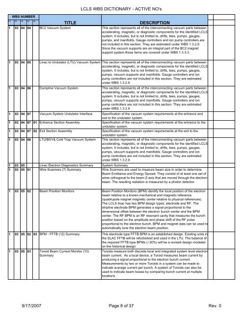
1 03 04 04 BC2 Vacuum System This section represents all of the interconnecting vacuum parts between<br />
accelerating, magnetic, or diagnostic components for the identified <strong>LCLS</strong><br />
system. It includes, but is not limited to, drifts, tees, pumps, gauges,<br />
pumps, and manifolds. Gauge controllers and ion pump controllers are<br />
not included in this section. They are estimated under <strong>WBS</strong> 1.3.2.9.<br />
Since the vacuum supports are an integral part of the BC2 magnet<br />
support system those items are covered under <strong>WBS</strong> 1.3.3.3.<br />
1 03 04 05 Linac to Undulator (LTU) Vacuum System This section represents all of the interconnecting vacuum parts between<br />
accelerating, magnetic, or diagnostic components for the identified <strong>LCLS</strong><br />
system. It includes, but is not limited to, drifts, tees, pumps, gauges,<br />
pumps, vacuum supports and manifolds. Gauge controllers and ion<br />
pump controllers are not included in this section. They are estimated<br />
under <strong>WBS</strong> 1.3.2.9<br />
1 03 04 06 Dumpline Vacuum System This section represents all of the interconnecting vacuum parts between<br />
accelerating, magnetic, or diagnostic components for the identified <strong>LCLS</strong><br />
system. It includes, but is not limited to, drifts, tees, pumps, gauges,<br />
pumps, vacuum supports and manifolds. Gauge controllers and ion<br />
pump controllers are not included in this section. They are estimated<br />
under <strong>WBS</strong> 1.3.2.9<br />
1 03 04 07 Vacuum System Undulator Interface Specification of the vacuum system requirements at the entrance and<br />
exit to the undulator system.<br />
1 03 04 07 01 Entrance Section Assembly Specification of the vacuum system requirements at the entrance to the<br />
undulator system.<br />
1 03 04 07 02 Exit Section Assembly Specification of the vacuum system requirements at the exit to the<br />
undulator system.<br />
1 03 04 08 LTU/BSY& Cold Trap Vacuum System This section represents all of the interconnecting vacuum parts between<br />
accelerating, magnetic, or diagnostic components for the identified <strong>LCLS</strong><br />
system. It includes, but is not limited to, drifts, tees, pumps, gauges,<br />
pumps, vacuum supports and manifolds. Gauge controllers and ion<br />
pump controllers are not included in this section. They are estimated<br />
under <strong>WBS</strong> 1.3.2.9<br />
1 03 05 Linac Electron Diagnostics Summary System Summary<br />
1 03 05 01 Wire Scanners (7) Summary Wire Scanners are used to measure beam size in order to determine<br />
Beam Emittance and Energy Spread. They consist of at least one set of<br />
wires orthogonal to the beam Z-axis that are moved through the electron<br />
beam. The resulting radiation is measured by a photon detector.<br />
1 03 05 02 Beam Position Monitors Beam Position Monitors (BPM) identify the local position of the electron<br />
beam relative to a known mechanical and magnetic reference<br />
(quadrupole magnet magnetic center relative to physical references).<br />
The <strong>LCLS</strong> linac has two BPM design types; electrode and RF. The<br />
stripline electrode BPM generates a signal proportional to the<br />
dimensional offset between the electron bunch center and the BPM<br />
center. The RF BPM is an RF resonant cavity that measures the bunch<br />
position based on the amplitude and phase shift of the RF pulse<br />
proportional to the electron bunch. BPM and magnet data can be used to<br />
automatically tune the electron beam position.<br />
1 03 05 02 03 BPM - FFTB (12) Summary This electrode type FFTB BPM is an established design. Existing units in<br />
the SLAC FFTB will be refurbished and used in the LTU. The balance of<br />
the required FFTB type BPMs (~30%) will be a revised design modeled<br />
on the historical design.<br />
1 03 05 03 Toroid Beam Current Monitor (10)<br />
Summary<br />
Toroids measure both discrete local and integrated system level electron<br />
beam current. As a local device, a Toroid measures beam current by<br />
producing a signal proportional to the electron bunch current.<br />
Measurements by two or more Toroids in a system can be made to<br />
indicate average current per bunch. A system of Toroids can also be<br />
used to indicate beam losses by comparing bunch current at multiple<br />
locations.<br />
9/17/2007 Page 8 of 37 Rev. 0