Mounting instructions for the retractable undercarriage - FEMA ...
Mounting instructions for the retractable undercarriage - FEMA ...
Mounting instructions for the retractable undercarriage - FEMA ...

You also want an ePaper? Increase the reach of your titles
YUMPU automatically turns print PDFs into web optimized ePapers that Google loves.
1<br />
<strong>Mounting</strong> <strong>instructions</strong><br />
<strong>for</strong> <strong>the</strong> <strong>retractable</strong> <strong>undercarriage</strong><br />
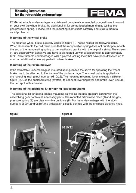
<strong>FEMA</strong> <strong>retractable</strong> <strong>undercarriage</strong>s are delivered completely assembled, you just have to mount<br />
on your own <strong>the</strong> wheel brake, <strong>the</strong> additional kit <strong>for</strong> spring-loaded mounting as well as <strong>the</strong><br />
gas pressure spring. Please read <strong>the</strong> mounting <strong>instructions</strong> carefully and stick to <strong>the</strong>m to<br />
avoid problems.<br />
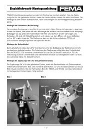
<strong>Mounting</strong> of <strong>the</strong> wheel brake<br />
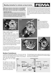
The mounted wheel brake is clearly visible in figure (I). Please regard <strong>the</strong> following steps.<br />
When disassemble <strong>the</strong> bolt make sure that <strong>the</strong> recuperation spring does not burst open. Attach<br />
<strong>the</strong> end of <strong>the</strong> recuperating spring to <strong>the</strong> oscillating cranks with <strong>the</strong> help of a string. The screws<br />
(1) are secured with adhesive and have to be heated up with a soldering bit to approximately<br />
80°C. All <strong>retractable</strong> <strong>undercarriage</strong>s with a pierced locking lever that have been delivered up to<br />
now can additionally be equipped with wheel brakes.<br />
<strong>Mounting</strong> of <strong>the</strong> reversing lever<br />
If <strong>the</strong> <strong>retractable</strong> <strong>undercarriage</strong> is mounted spring-loaded <strong>the</strong> servo <strong>for</strong> operating <strong>the</strong> wheel<br />
brake has to be attached to <strong>the</strong> frame of <strong>the</strong> <strong>undercarriage</strong>. The wheel brake is applied via<br />
<strong>the</strong> reversing lever (stock number 9810/22). The mounted reversing lever is clearly visible on<br />
figure (II). Use <strong>the</strong> enclosed string (twofold) to connect reversing lever and brake lever. Secure<br />
<strong>the</strong> tied spot with adhesive.<br />
<strong>Mounting</strong> of <strong>the</strong> additional kit <strong>for</strong> spring-loaded mounting<br />
The additional kit <strong>for</strong> spring-loaded mounting as well as <strong>the</strong> gas-pressure spring with <strong>the</strong><br />
assembling gear contain all necessary parts. The mounted articulation piece (1) and <strong>the</strong> gas<br />
pressure spring (2) are clearly visible on figure (II). For <strong>the</strong> <strong>undercarriage</strong>s with <strong>the</strong> stock<br />
numbers 9800A and 9810A <strong>the</strong> articulation piece is centred with <strong>the</strong> enclosed distance rings.<br />
fi gure I fi gure II<br />
1<br />
9810/22<br />
2<br />
1
2<br />
<strong>Mounting</strong> <strong>instructions</strong><br />
<strong>for</strong> <strong>the</strong> <strong>retractable</strong> <strong>undercarriage</strong><br />
Firm attachment between two fuselage bulkheads<br />
Attach <strong>the</strong> <strong>retractable</strong> <strong>undercarriage</strong> carefully to avoid problems in flight practice. Please regard<br />
<strong>the</strong> following notes thoroughly.<br />
Up to four servos can be attached to <strong>the</strong> <strong>undercarriage</strong>s with <strong>the</strong> stock numbers 9800A, 9810A<br />
and 9820A. To <strong>the</strong> <strong>undercarriage</strong> with <strong>the</strong> stock number 9830 up to two servos can be attached.<br />
The supports have all necessary fastening bores. The wheel bow of stainless spring steel<br />
makes <strong>the</strong> retraction easier and guarantees a safe functioning of <strong>the</strong> fuselage flaps.<br />
Position of <strong>the</strong> <strong>retractable</strong> <strong>undercarriage</strong> in <strong>the</strong> fuselage<br />
At most modern sail planes, <strong>the</strong> axle of <strong>the</strong> extended wheel is located just vertically below <strong>the</strong><br />
leading edge stringer strip. The aeromodelling practice, however, has shown that <strong>the</strong> model too<br />
easily bends its nose down when starting a towed flight and landing. It is advisable to mount<br />
<strong>the</strong> axle nearer to <strong>the</strong> front of <strong>the</strong> model. We recommend to shift it 5-15° to <strong>the</strong> front in relation<br />
to <strong>the</strong> vertical below <strong>the</strong> stringer strip.<br />
Fuselage opening and position of <strong>the</strong> fl aps<br />
The width of <strong>the</strong> opening should be 2 mm smaller than <strong>the</strong> dimension “B” of <strong>the</strong> <strong>undercarriage</strong>.<br />
The length of <strong>the</strong> opening depends on <strong>the</strong> wheel diameter. Determine <strong>the</strong> dimension of <strong>the</strong> front<br />
edge of <strong>the</strong> oscillating cranks (extended) and measure <strong>the</strong> round shape of <strong>the</strong> flaps according<br />
to <strong>the</strong> graphic. The preparation of a firm cardboard template is advisable <strong>for</strong> <strong>the</strong> superficial<br />
fissure of <strong>the</strong> saw line. The stronger <strong>the</strong> superficial fissure, <strong>the</strong> easier to use <strong>the</strong> saw. A small<br />
electronic compass saw is ideal, but if not available it is also possible to use <strong>the</strong> saw blade of a<br />
small coping saw. Separate <strong>the</strong> cut out piece right in <strong>the</strong> middle. A piece of a racing cycle’s thin<br />
tube is suitable as hinge <strong>for</strong> <strong>the</strong> flaps. Cut off strips that are 2 cm wide and of <strong>the</strong> appropriate<br />
length. Punch holes into <strong>the</strong> middle of <strong>the</strong> rubber strip with <strong>the</strong> help of a splayed brass pipe<br />
(see graphic). These hinges are really robust and adapt to <strong>the</strong> bulging of <strong>the</strong> fuselage. They<br />
are stuck toge<strong>the</strong>r from <strong>the</strong> inside with instant adhesive first to <strong>the</strong> fuselage and <strong>the</strong>n to <strong>the</strong><br />
flap. The gap between fuselage and flap should amount 1 mm. Prepare <strong>the</strong> two stopping points<br />
“Y” out of a sheet or an epoxy plate and stick <strong>the</strong>m toge<strong>the</strong>r. The flaps can be shut with <strong>the</strong><br />
help of small springs of rubber band.<br />
front bulkhead<br />
stopping point<br />
hook “X”<br />
hinges<br />
support of <strong>the</strong> <strong>undercarriage</strong><br />
direction of flight<br />
back<br />
bulkhead<br />
flaps<br />
stopping point
3<br />
<strong>Mounting</strong> <strong>instructions</strong><br />
<strong>for</strong> <strong>the</strong> <strong>retractable</strong> <strong>undercarriage</strong><br />
Preparation and mounting of <strong>the</strong> bulkheads<br />
Use plywood 8-12 mm thick. Prepare a cardboard template according to <strong>the</strong> cross-section of<br />
<strong>the</strong> fuselage. Ascertain <strong>the</strong> mounting height of <strong>the</strong> <strong>retractable</strong> <strong>undercarriage</strong> in <strong>the</strong> fuselage<br />
(between 1-5 cm) from <strong>the</strong> lower edge of <strong>the</strong> support. Then cut <strong>the</strong> openings <strong>for</strong> <strong>the</strong> support<br />
into <strong>the</strong> template and try if it fits into <strong>the</strong> fuselage. Prepare <strong>the</strong> plywood bulkheads according to<br />
this template and test <strong>the</strong>ir shape in <strong>the</strong> fuselage. Make sure that <strong>the</strong> <strong>undercarriage</strong> is mounted<br />
exactly in longitudinal direction and does not incline on <strong>the</strong> sides. The bulkheads are stuck into<br />
<strong>the</strong> fuselage with concentrated epoxy resin. When <strong>the</strong> resin has cured, <strong>the</strong> <strong>undercarriage</strong> is<br />
taken out and <strong>the</strong> bulkheads are stuck with glass fabric ribbon solidly to <strong>the</strong> fuselage. Prepare<br />
a holding bow of very solid beech wood and screw it with 4 wooden screws to <strong>the</strong> bulkhead<br />
at <strong>the</strong> very front. You can also use a holding bow made out of aluminium sheet (2-3 mm thick)<br />
and screw it on <strong>the</strong> face of <strong>the</strong> bulkhead.<br />
wooden screws<br />
holding bow<br />
front bulkhead<br />
back bulkhead<br />
<strong>Mounting</strong> of <strong>the</strong> servos and rods<br />
Cut out <strong>the</strong> servo holding (stock number 9810/10) according to <strong>the</strong> size of <strong>the</strong> servo. A slowly<br />
running 180° servo is perfect <strong>for</strong> <strong>the</strong> operation of <strong>the</strong> <strong>undercarriage</strong>, but it is also possible to<br />
built in a 3-6 kg normal servo. Use an M3 <strong>for</strong>k head and an M3 ball head to prepare <strong>the</strong> rods of<br />
<strong>the</strong> <strong>undercarriage</strong>. When adjusting make sure that both final positions are safely reached even<br />
though <strong>the</strong> servo must not be under load. It is advisable <strong>for</strong> bigger models to attach <strong>the</strong> servo<br />
of <strong>the</strong> elevator onto <strong>the</strong> vertical rudder unit. The servos <strong>for</strong> <strong>retractable</strong> <strong>undercarriage</strong>, vertical<br />
rudder and tow release should be attached at <strong>the</strong> side of <strong>the</strong> <strong>retractable</strong> <strong>undercarriage</strong>. The<br />
coupling of <strong>the</strong> vertical rudder can be prepared neatly with two cable controls made out of<br />
cord. After adjusting <strong>the</strong> driving lever <strong>for</strong> <strong>the</strong> locking of <strong>the</strong> <strong>undercarriage</strong> it is advisable to grind<br />
off <strong>the</strong> area of <strong>the</strong> steel shaft onto which <strong>the</strong> fastening screw is pressing and thus making<br />
a positive fit.
4<br />
<strong>Mounting</strong> <strong>instructions</strong><br />
<strong>for</strong> <strong>the</strong> <strong>retractable</strong> <strong>undercarriage</strong><br />
Wheel brake<br />
The wheel brake is applied by a servo and thus can be used very sensitively even despite<br />
<strong>the</strong> high brake <strong>for</strong>ce. If <strong>the</strong> <strong>retractable</strong> <strong>undercarriage</strong> is attached firmly, <strong>the</strong> brake servo can be<br />
mounted ei<strong>the</strong>r directly to <strong>the</strong> frame of <strong>the</strong> <strong>undercarriage</strong> or to <strong>the</strong> front fastening bulkhead.<br />
The wheel brake can also be applied in combination with <strong>the</strong> landing flaps or <strong>the</strong> tow release.<br />
If <strong>the</strong> <strong>retractable</strong> <strong>undercarriage</strong> is attached spring-loaded <strong>the</strong> brake servo has to be mounted<br />
to <strong>the</strong> frame of <strong>the</strong> <strong>undercarriage</strong> to secure <strong>the</strong> safe functioning of <strong>the</strong> wheel brake during<br />
spring-deflection.<br />
When adjusting <strong>the</strong> brake functioning make sure that <strong>the</strong> arrester wire is not too tight while<br />
<strong>the</strong> <strong>undercarriage</strong> is extended. The arrester wire should be tight but <strong>the</strong> brake should not be<br />
applied yet.<br />
Additional <strong>instructions</strong> <strong>for</strong> spring-loaded attachment<br />
When mounting spring-loaded <strong>undercarriage</strong>s it is very important to attach <strong>the</strong> back bulkhead<br />
which is needed as limit stop and lateral guide. O<strong>the</strong>rwise tough touch-downs or crosswind<br />
landings may damage <strong>the</strong> fuselage. When mounting <strong>the</strong> wheel brake, additionally attach a<br />
plywood adapter 10 mm thick between <strong>the</strong> aluminium pillow block of <strong>the</strong> <strong>retractable</strong> <strong>undercarriage</strong><br />
and <strong>the</strong> front fastening bulkhead so that <strong>the</strong> front fuselage bulkhead does not hinder <strong>the</strong><br />
reversing lever (stock number 9810-22) after <strong>the</strong> spring deflection.<br />
Preparing <strong>the</strong> bulkheads<br />
It is advisable to prepare cardboard templates be<strong>for</strong>e preparing bulkheads out of plywood<br />
(8-10 mm). Stick to <strong>the</strong> following steps to get exactly symmetrical components:<br />
1. Fold a square cardboard right in <strong>the</strong> middle.<br />
2. Cut out <strong>the</strong> rough contour of <strong>the</strong> fuselage.<br />
3. Unfold <strong>the</strong> cardboard and hold it up to <strong>the</strong> corresponding position in <strong>the</strong> fuselage.<br />
Repeat steps 1 to 3 until <strong>the</strong> template has <strong>the</strong> same contour as <strong>the</strong> fuselage. After preparing<br />
templates <strong>for</strong> both bulkheads, transfer <strong>the</strong> contours onto <strong>the</strong> plywood. Include also <strong>the</strong> fold<br />
which is needed as a symmetrical line to draw <strong>the</strong> necessary borings and gaps <strong>for</strong> <strong>the</strong><br />
<strong>undercarriage</strong>. Now saw out <strong>the</strong> bulkheads.<br />
guide bulkhead (back) fastening bulkhead (front)<br />
gap <strong>for</strong> lateral guide<br />
of <strong>the</strong> <strong>undercarriage</strong> upper limit stop<br />
lower limit stop<br />
gap <strong>for</strong> damper
5<br />
<strong>Mounting</strong> <strong>instructions</strong><br />
<strong>for</strong> <strong>the</strong> <strong>retractable</strong> <strong>undercarriage</strong><br />
Fix <strong>the</strong> lower limit stop in such a way that <strong>the</strong> <strong>retractable</strong> <strong>undercarriage</strong> rests with an initial<br />
stress of 1-2 mm. The lateral guide should not have more than 0.5 mm of positive allowance.<br />
We recommend to screw plastic ledges onto <strong>the</strong> bulkhead <strong>for</strong> <strong>the</strong> lateral guide that can <strong>the</strong>n be<br />
adjusted very precisely. Grease <strong>the</strong> guide a bit to obtain a safe functioning.<br />
Fix <strong>the</strong> upper limit stop in such a way that <strong>the</strong> spring deflected wheel rises at least 30 mm<br />
above <strong>the</strong> flaps of <strong>the</strong> fuselage.<br />
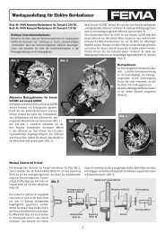
<strong>Mounting</strong> of <strong>undercarriage</strong> and of gas pressure spring<br />
Calculate <strong>the</strong> required springiness of <strong>the</strong> gas pressure spring according to <strong>the</strong> following<br />
thumbrule:<br />
springiness (N) = model weight in kg x 40 (1kp ca. 10N)<br />
Gas pressure springs are available with a springiness of 200N, 300N and 400N. Models of<br />
more than 10 kg require <strong>the</strong> attachment of two gas pressure springs. If additionally a wheel<br />
brake is attached, <strong>the</strong> second gas pressure spring has to be mounted eccentric to leave space<br />
<strong>for</strong> <strong>the</strong> reversing lever (stock number 9810/22).<br />
The lateral <strong>for</strong>ce has no negative influence on <strong>the</strong> functioning of <strong>the</strong> spring. If <strong>the</strong> gas pressure<br />
springs have a different springiness <strong>the</strong> weaker one is attached eccentric.<br />
Screw <strong>the</strong> <strong>undercarriage</strong> with <strong>the</strong> mounted dampers to <strong>the</strong> fastening bulkhead (don’t <strong>for</strong>get <strong>the</strong><br />
plain washer). Lead <strong>the</strong> fastening strips of <strong>the</strong> damper that are not yet tangent-bent through <strong>the</strong><br />
gap of <strong>the</strong> fastening bulkhead past <strong>the</strong> sides of <strong>the</strong> dampers (according to <strong>the</strong> general view).<br />
Then connect damper and fastening strips of <strong>the</strong> damper with <strong>the</strong> spring steel bolt. Then keep<br />
<strong>the</strong> damper in <strong>the</strong> desired position and make sure <strong>the</strong> guide bulkhead of <strong>the</strong> <strong>undercarriage</strong><br />
is surface-mounted on <strong>the</strong> lower limit stop. Align both fastening strips exactly parallel to <strong>the</strong><br />
dampers. A short piece of <strong>the</strong> fastening strips protrudes <strong>the</strong> end of <strong>the</strong> fastening bulkhead.<br />
Draw a line at <strong>the</strong>se edges. According to <strong>the</strong> line <strong>the</strong> two fastening strips can be tangent-bend<br />
with <strong>the</strong> help of a vise (once to <strong>the</strong> left and once to <strong>the</strong> right) . Then just drill a fastening bore<br />
through bulkhead and fastening strip to screw everything up. The spring steel bolt is secured<br />
against lateral shifting by <strong>the</strong> included slide index (according to <strong>the</strong> general view).<br />
front fastening bulkhead<br />
after spring deflection at least 30 mm<br />
back guide bulkhead<br />
<strong>retractable</strong> <strong>undercarriage</strong>
6<br />
<strong>Mounting</strong> <strong>instructions</strong><br />
<strong>for</strong> <strong>the</strong> <strong>retractable</strong> <strong>undercarriage</strong><br />
general view top view<br />
plywood adapter<br />
10 mm thick<br />
when mounting <strong>the</strong> wheel brake<br />
For very rough flight practice we recommend mounting <strong>the</strong> thrust bearing according to figure<br />
III. This fastening method relieves <strong>the</strong> fastening bulkhead as <strong>the</strong> <strong>for</strong>ces are lead directly to <strong>the</strong><br />
fuselage. The additional longitudinal bulkheads<br />
and <strong>the</strong> transverse bulkhead give <strong>the</strong> <strong>undercarriage</strong><br />
an optimal support.<br />
stock number<br />
fi gure III<br />
scale model:measures in mm servo holder<br />
bow<br />
*without wheel, servo holder and bow<br />
A B C D E F weight model weight<br />
9800A 272 80 68 140 - 165 66 92 680 g 12 - 25 kg<br />
9810A 220 72 60 110 - 127 56 68 420 g 8 - 16 kg<br />
9820A 196 62 50 90 - 100 46 60 350 g 5 - 10 kg<br />
9830 172 54 44 70 -80 36 54 200 g 3 - 7 kg<br />
Böhler GmbH · Obere Rebbergstr.11 · D-77709 Wolfach · Tel.07834/303 · Fax 07834/47735