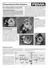
Assembly instructions for electronic on-board starters - FEMA ...
Assembly instructions for electronic on-board starters - FEMA ...
Assembly instructions for electronic on-board starters - FEMA ...

Create successful ePaper yourself
Turn your PDF publications into a flip-book with our unique Google optimized e-Paper software.
<str<strong>on</strong>g>Assembly</str<strong>on</strong>g> <str<strong>on</strong>g>instructi<strong>on</strong>s</str<strong>on</strong>g> <str<strong>on</strong>g>for</str<strong>on</strong>g> <str<strong>on</strong>g>electr<strong>on</strong>ic</str<strong>on</strong>g> <strong>on</strong>-<strong>board</strong> <strong>starters</strong><br />
Important safety in<str<strong>on</strong>g>for</str<strong>on</strong>g>mati<strong>on</strong>:<br />
Please note that a combusti<strong>on</strong> engine with built-in <str<strong>on</strong>g>electr<strong>on</strong>ic</str<strong>on</strong>g><br />
<strong>on</strong>-<strong>board</strong> starter is not a toy. The combusti<strong>on</strong> engine might<br />
start suddenly due to an unintenti<strong>on</strong>al activati<strong>on</strong>. Please read<br />
the safety in<str<strong>on</strong>g>for</str<strong>on</strong>g>mati<strong>on</strong> in the assembly <str<strong>on</strong>g>instructi<strong>on</strong>s</str<strong>on</strong>g> and in the<br />
appendix thoroughly.<br />
Recommended starter battery:<br />
Only high-amperage (16A) NC, NiMh and LiPo batteries<br />
(as used <str<strong>on</strong>g>for</str<strong>on</strong>g> <str<strong>on</strong>g>electr<strong>on</strong>ic</str<strong>on</strong>g> fl ying models) are suitable as starter<br />
batteries.<br />
In<str<strong>on</strong>g>for</str<strong>on</strong>g>mati<strong>on</strong> <strong>on</strong> the operati<strong>on</strong> of the <strong>on</strong>-<strong>board</strong> starter:<br />
The maximum operating time of the <strong>on</strong>-<strong>board</strong> starter is 10<br />
secs. The maximum operating temperature of the <strong>on</strong>-<strong>board</strong><br />
starter must not exceed 70°C.<br />
<str<strong>on</strong>g>Assembly</str<strong>on</strong>g> <str<strong>on</strong>g>instructi<strong>on</strong>s</str<strong>on</strong>g> <str<strong>on</strong>g>for</str<strong>on</strong>g>:<br />
Stock number 9500 Basic kit <str<strong>on</strong>g>for</str<strong>on</strong>g> 7.5-14 cc engines<br />
Stock number 9512 Basic kit <str<strong>on</strong>g>for</str<strong>on</strong>g> 15-35 cc engines<br />
Stock number 9514 Complete kit <str<strong>on</strong>g>for</str<strong>on</strong>g> OS-Max BGX-1, OS-<br />
Max 160 FX, Moki-25, Magnum<br />
XL180AR, Laser 200, MVVS-35 (Glow)<br />
General in<str<strong>on</strong>g>for</str<strong>on</strong>g>mati<strong>on</strong>:<br />
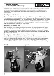
The universal <strong>on</strong>-<strong>board</strong> starting system in Fig. 1 <str<strong>on</strong>g>for</str<strong>on</strong>g> aircraft engines<br />
can be attached to all comm<strong>on</strong> single cylinder glow plug<br />
engines.<br />
Not included in the kit:<br />
In additi<strong>on</strong> to the basic kit each engine type requires an adapter<br />
kit. You fi nd the available adapter kits in our catalog and price<br />
list.<br />
When using the Glow-C<strong>on</strong>trol you <strong>on</strong>ly need a storage battery<br />
<str<strong>on</strong>g>for</str<strong>on</strong>g> the operati<strong>on</strong> of the <strong>on</strong>-<strong>board</strong> starter, which supplies the<br />
starter engine and the glow plug<br />
.<br />
The universal <strong>on</strong>-<strong>board</strong> starting system can also be attached as<br />
a compact versi<strong>on</strong> (see Fig 2). The holder plate is not included<br />
in the delivery, you can build it <strong>on</strong> your own.<br />
- 1 -<br />
Warranty<br />
Our electric <strong>on</strong>-<strong>board</strong> <strong>starters</strong> are shipped as kits. The<br />
professi<strong>on</strong>al assembly and normal operati<strong>on</strong> is bey<strong>on</strong>d our<br />
infl uence. There<str<strong>on</strong>g>for</str<strong>on</strong>g>e the warranty is limited to comp<strong>on</strong>ents<br />
included in the kit as well as their functi<strong>on</strong>ing. We assume<br />
no liability <str<strong>on</strong>g>for</str<strong>on</strong>g> damages resulting from improper assembly or<br />
operati<strong>on</strong>.<br />
Recommendati<strong>on</strong> <str<strong>on</strong>g>for</str<strong>on</strong>g> the running-in of the <strong>on</strong><strong>board</strong><br />
starter:<br />
After the complete assembly of the <strong>on</strong>-<strong>board</strong> starter <strong>on</strong> the<br />
internal combusti<strong>on</strong> engine we recommend to disassemble<br />
the glow plug and to let the <strong>on</strong>-<strong>board</strong> starter run in <str<strong>on</strong>g>for</str<strong>on</strong>g> approx.<br />
3 minutes. Then you can put the <strong>on</strong>-<strong>board</strong> starter into<br />
operati<strong>on</strong>.<br />
Fig. 1 Fig. 2<br />
Basically, the <str<strong>on</strong>g>electr<strong>on</strong>ic</str<strong>on</strong>g> <strong>on</strong>-<strong>board</strong> starting system can run in two<br />
operati<strong>on</strong> modes:<br />
Starting of the internal combusti<strong>on</strong> engine via the radio<br />
c<strong>on</strong>trol<br />
At this operati<strong>on</strong> mode, the internal combusti<strong>on</strong> engine can be<br />
started <strong>on</strong> the ground as well as in the air via the radio c<strong>on</strong>trol.<br />
Here, the NC-storage battery is placed inside the model.<br />
Safe starting of the internal combusti<strong>on</strong> engine is <strong>on</strong>ly<br />
possible <strong>on</strong> the ground<br />
This operating mode <strong>on</strong>ly requires the attachment of the starting<br />
device with the starter engine inside the model. The starter storage<br />
battery and the Glow-C<strong>on</strong>trol are placed inside a starting<br />
box. The <strong>on</strong>-<strong>board</strong> starter is manually switched <strong>on</strong> and off via<br />
micro switches.<br />
C<strong>on</strong>trol of electric <strong>on</strong>-<strong>board</strong> starting system<br />
The electric <strong>on</strong>-<strong>board</strong> starter is c<strong>on</strong>trolled via micro switches<br />
operated from an IC-servo.
<str<strong>on</strong>g>Assembly</str<strong>on</strong>g> <str<strong>on</strong>g>instructi<strong>on</strong>s</str<strong>on</strong>g> <str<strong>on</strong>g>for</str<strong>on</strong>g> <str<strong>on</strong>g>electr<strong>on</strong>ic</str<strong>on</strong>g> <strong>on</strong>-<strong>board</strong> <strong>starters</strong><br />
For the secure starting of the internal combusti<strong>on</strong> engine it is<br />
necessary that, at the activati<strong>on</strong> of the engine, the starter engine<br />
starts immediately with full power to prevent the kick-back of<br />
the combusti<strong>on</strong> engine. (Please do not use electric c<strong>on</strong>trollers.)<br />
Power supply of the electric <strong>on</strong>-<strong>board</strong> starter<br />
The power supply of the starter engine and of the heater plug<br />
<strong>on</strong>ly requires a storage battery to which also the Glow-C<strong>on</strong>trol<br />
is c<strong>on</strong>nected.<br />
Recommendati<strong>on</strong> <str<strong>on</strong>g>for</str<strong>on</strong>g> starting storage batteries:<br />
9.6 - 12 Volt, min. 1.8 Ah.<br />
Adapters <str<strong>on</strong>g>for</str<strong>on</strong>g> 7.5 - 35 cc aircraft engines<br />
In additi<strong>on</strong> to the basic kit, an adapter is necessary <str<strong>on</strong>g>for</str<strong>on</strong>g><br />
each engine type. Adapters can be combined individually <str<strong>on</strong>g>for</str<strong>on</strong>g><br />
internal combusti<strong>on</strong> engines that are not listed above. Please<br />
specify with your order thread = d1 and diameter = d2.<br />
Available clamping rings and thrust washers:<br />
d2: 6.0; 7.0: 8.0; 9.5; 10; 12 (mm)<br />
Available nuts: d1: M6; M7; M8; 1/4-28UNF,<br />
5/16-24UNF, 3/8-24UNF, M8x1, M10x1<br />
<str<strong>on</strong>g>Assembly</str<strong>on</strong>g> of the support, plate and bearing with gear<br />
When the gearwheel is mounted, the support and the<br />
bearing with gear are attached. (Fig. 4.)<br />
The plate and the attached bearing with gear are<br />
temporarily screwed to both supports with the supports<br />
evenly placed. Then put the combusti<strong>on</strong> engine <strong>on</strong>to the<br />
support so that the gearwheel and gear are exactly <strong>on</strong> top of<br />
each other. Now the fi xing holes <str<strong>on</strong>g>for</str<strong>on</strong>g> the combusti<strong>on</strong> engine<br />
can be drilled into both supports (fi rmly clamp the supports<br />
to the combusti<strong>on</strong> engine). When the combusti<strong>on</strong> engine is<br />
- 2 -<br />
Instructi<strong>on</strong>s <str<strong>on</strong>g>for</str<strong>on</strong>g> the installati<strong>on</strong> of the mechanical<br />
comp<strong>on</strong>ents<br />
<str<strong>on</strong>g>Assembly</str<strong>on</strong>g> of the freewheeling gear<br />
First, remove the nut, holder disc and propeller adapter<br />
from the combusti<strong>on</strong> engine. During the mounting of the<br />
freewheeling gear please stick exactly to Fig. 3. Lubricate<br />
the inside and the fr<strong>on</strong>t side of the freewheel generously<br />
with the enclosed high pressure grease.<br />
Make sure that the rollers d<strong>on</strong>’t fall out of the freewheel.<br />
The adapter can be easily inserted into the freewheel<br />
by turning it clockwise. The fl ange of the thrust washer<br />
is turned towards the combusti<strong>on</strong> engine. The mounted<br />
freewheeling gear has an axial tolerance and can be easily<br />
cranked against the starting directi<strong>on</strong>, but immediately<br />
engages in starting directi<strong>on</strong>.<br />
holder disclaimer thrust washer<br />
nut clamping ring<br />
screwed to the supports of the intended engine support, the<br />
mounting bolts of the plate are fi nally tightened.<br />
Note:<br />
The gear (10 teeth) must not exert edgewise pressure<br />
<strong>on</strong> the freewheeling gear as this would destroy the freewheel.<br />
Please adjust the tooth tolerance carefully. The<br />
maximum operating temperature at the freewheel must<br />
not exceed +70°C.<br />
Fig. 3
<str<strong>on</strong>g>Assembly</str<strong>on</strong>g> <str<strong>on</strong>g>instructi<strong>on</strong>s</str<strong>on</strong>g> <str<strong>on</strong>g>for</str<strong>on</strong>g> <str<strong>on</strong>g>electr<strong>on</strong>ic</str<strong>on</strong>g> <strong>on</strong>-<strong>board</strong> <strong>starters</strong><br />
<str<strong>on</strong>g>Assembly</str<strong>on</strong>g> of the Cardan shaft<br />
The Cardan shaft (Fig.5) helps you signifi cantly with the installati<strong>on</strong><br />
of the starter engine as no alignment works are necessary.<br />
The maximum defl ecti<strong>on</strong> is approx. 30 mm <strong>on</strong> a length of 100<br />
mm. During the assembly, stick exactly to Figure 5. If required,<br />
the shaft can be shortened which allows <str<strong>on</strong>g>for</str<strong>on</strong>g> an ideal adapti<strong>on</strong> to<br />
the particular fi tting c<strong>on</strong>diti<strong>on</strong>s. After the shortening, h<strong>on</strong>e the<br />
surface of the adapter to ensure a secure power transmissi<strong>on</strong>.<br />
The Cardan shaft has a predetermined breaking point in the<br />
shape of a cut notch to protect the gear wheels. When shortening<br />
the Cardan shaft make sure that the notch is preserved.<br />
Important:<br />
The adapter pins have to be twisted by 90°. This has to be<br />
c<strong>on</strong>sidered when h<strong>on</strong>ing the surface of the adapter.<br />
Fig. 6<br />
- 3 -<br />
Fig. 4<br />
<str<strong>on</strong>g>Assembly</str<strong>on</strong>g> of the starter engine with gearbox<br />
<str<strong>on</strong>g>for</str<strong>on</strong>g> stock number 9500<br />
The assembly of the starter engine with gearbox is clearly outlined<br />
in Fig. 6 . Lubricate the shaft and the gear wheel prior to the<br />
assembly. Examine the smooth operati<strong>on</strong> of the complete unit.<br />
<str<strong>on</strong>g>Assembly</str<strong>on</strong>g> of the starter engine with gearbox<br />
<str<strong>on</strong>g>for</str<strong>on</strong>g> stock numbers 9512 and 9514<br />
The gearbox <str<strong>on</strong>g>for</str<strong>on</strong>g> this design is pre-assembled. You just have<br />
to screw it to the starter engine (Fig. 7).<br />
The mechanical assembly of the <strong>on</strong>-<strong>board</strong> starter is now completed.<br />
Fig. 5<br />
Fig. 7
<str<strong>on</strong>g>Assembly</str<strong>on</strong>g> <str<strong>on</strong>g>instructi<strong>on</strong>s</str<strong>on</strong>g> <str<strong>on</strong>g>for</str<strong>on</strong>g> <str<strong>on</strong>g>electr<strong>on</strong>ic</str<strong>on</strong>g> <strong>on</strong>-<strong>board</strong> <strong>starters</strong><br />
Spare parts <str<strong>on</strong>g>for</str<strong>on</strong>g> 9500 9512 9514<br />
Support, 2 units 9500/01 9512/01 9512/01<br />
Plate 9500/02 9512/02 9514/01<br />
Bearing 9500/03 9500/03 9500/03<br />
Freewheeling gear, 60/76/92 teeth, m=0.8 9500/05 9512/05 9712/04<br />
Gear, 10 teeth, m=0.8 9500/06 9500/06 9500/06<br />
Adapter 9500/07 9518/07 9712/07<br />
Cardan shaft 9515/07 9515/07 9515/07<br />
Starter engine with gearbox 9580/01 9570/01 9570/01<br />
Gearbox, single 9580/02 9570/02 9570/02<br />
Starter engine with gear, 12 teeth, m = 0.5 9580/05 9575/03 9575/03<br />
Aluminium gear with output shaft, 66 teeth 9580/04 9570/04 9570/04<br />
Gear <str<strong>on</strong>g>for</str<strong>on</strong>g> starter engine, 12 teeth, m = 0.5 9570/03 9570/03 9570/03<br />
Micro switch, single 9560/04 9560/04 9560/04<br />
Board switch, 16A 9560/07 9560/07 9560/07<br />
Small parts kit (not shown) 9500/12 9512/12 9514/12<br />
Thrust washer 9530/35<br />
C<strong>on</strong>e ring 9530/26<br />
Spare parts <str<strong>on</strong>g>for</str<strong>on</strong>g> 9500, 9512, 9514<br />
plate<br />
freewheeling gear<br />
<strong>on</strong>-<strong>board</strong> switch<br />
support<br />
gear<br />
Cardan shaft<br />
adapter thrust washer<br />
starter engine<br />
with gear<br />
bearing<br />
micro switch<br />
c<strong>on</strong>e ring<br />
aluminium gear<br />
with output shaft<br />
starter engine with gearbox<br />
gearbox<br />
single<br />
Table with dimensi<strong>on</strong>s (dimensi<strong>on</strong>s in mm ) / weight (without starter storage battery)<br />
type A B C D E F<br />
9500 29,0 24,0 68,0 48,0 25,0 37,0<br />
9512 35,0 24,0 76,0 60,8 25,0 40,0<br />
9514 42,0 26,0 90,0 73,6 30,0 50,0<br />
- 4 -<br />
Dimensi<strong>on</strong>al drawing: Basic kit, stock number 9500/<br />
9512/ 9514<br />
B<br />
5<br />
A<br />
D<br />
View »A«<br />
»A«<br />
9,6<br />
C<br />
E<br />
F<br />
weight<br />
320 gr.<br />
380 gr.<br />
440 gr.
<str<strong>on</strong>g>Assembly</str<strong>on</strong>g> <str<strong>on</strong>g>instructi<strong>on</strong>s</str<strong>on</strong>g> <str<strong>on</strong>g>for</str<strong>on</strong>g> <str<strong>on</strong>g>electr<strong>on</strong>ic</str<strong>on</strong>g> <strong>on</strong>-<strong>board</strong> <strong>starters</strong><br />
C<strong>on</strong>trol of the <str<strong>on</strong>g>electr<strong>on</strong>ic</str<strong>on</strong>g> <strong>on</strong>-<strong>board</strong> starter<br />
General in<str<strong>on</strong>g>for</str<strong>on</strong>g>mati<strong>on</strong><br />
As shown in the circuit diagram, three switches are<br />
required <str<strong>on</strong>g>for</str<strong>on</strong>g> the c<strong>on</strong>trolling of the <strong>on</strong>-<strong>board</strong> starter which are<br />
c<strong>on</strong>nected in series. We recommend mounting the airborne<br />
starter countersunk to avoid an unintenti<strong>on</strong>al operati<strong>on</strong>.<br />
The »<strong>on</strong>-off« positi<strong>on</strong> of the switch has to be marked<br />
distinctly (Fig. I). The safety switch additi<strong>on</strong>ally prevents the<br />
starting while the throttle lever of the radio c<strong>on</strong>trol is not in<br />
the positi<strong>on</strong> of idle speed. The safety switch is operated via<br />
the gas servo and is <strong>on</strong>ly closed in idle speed positi<strong>on</strong>. Keep<br />
the actuating cams <strong>on</strong> the cam plate as short as possible<br />
(fi g. II).<br />
The micro switch <str<strong>on</strong>g>for</str<strong>on</strong>g> the starting and stopping of the starter<br />
engine is operated via the starter servo (fi g. III). For this<br />
Circuit diagram<br />
airborne switch<br />
yello<br />
starter engine<br />
Speed 480/600<br />
- 5 -<br />
functi<strong>on</strong> we recommend an IC servo with put-<strong>on</strong> polarityreversal<br />
switch (f. ex. Graupner C 508 with polarity-reversal<br />
switch stock number 3945).<br />
Attach the starter battery and the switches as near as<br />
possible to the combusti<strong>on</strong> engine. Make sure that the cables<br />
between the starter battery, safety switch, <strong>on</strong>-off switch and<br />
starter engine are as short as possible. They should have a<br />
minimal distance of 100 mm to receiver and antenna in order<br />
to avoid radio interferences.<br />
We recommend soldered juncti<strong>on</strong>s <str<strong>on</strong>g>for</str<strong>on</strong>g> wiring (plug<br />
c<strong>on</strong>necti<strong>on</strong>s cause an unnecessary transfer resistance).<br />
Tin-plate the fl exible wires prior to soldering them. After<br />
cooling check each soldering by shaking it. The starter<br />
battery is c<strong>on</strong>nected via high-quality plugs.<br />
Basically, the <str<strong>on</strong>g>electr<strong>on</strong>ic</str<strong>on</strong>g> <strong>on</strong>-<strong>board</strong> starting systems can run in<br />
two operati<strong>on</strong> modes.<br />
Status LED receiver<br />
Glow C<strong>on</strong>trol<br />
blue<br />
red<br />
black<br />
starter-accumulator<br />
LiPO-accu 3x cells<br />
(11,1 Volt) min. 1800 mAh<br />
safety switch On-Off-switch plug c<strong>on</strong>necti<strong>on</strong><br />
Fig. I airborne switch Fig. II safety switch Fig. III <strong>on</strong>-off-switch<br />
OFF<br />
ON<br />
helm disk plate cam<br />
helm disk<br />
throttle servo<br />
micro-switch starter-servo micro-switch
<str<strong>on</strong>g>Assembly</str<strong>on</strong>g> <str<strong>on</strong>g>instructi<strong>on</strong>s</str<strong>on</strong>g> <str<strong>on</strong>g>for</str<strong>on</strong>g> <str<strong>on</strong>g>electr<strong>on</strong>ic</str<strong>on</strong>g> <strong>on</strong>-<strong>board</strong> <strong>starters</strong><br />
1. Starting of the internal combusti<strong>on</strong> engine via the<br />
radio c<strong>on</strong>trol <strong>on</strong> ground and in air<br />
With this operati<strong>on</strong> mode, the internal combusti<strong>on</strong> engine<br />
can be started via the radio c<strong>on</strong>trol <strong>on</strong> the ground as well as<br />
in the air. The starter battery is placed inside the model (see<br />
circuit diagram).<br />
Operati<strong>on</strong> sequence:<br />
� On-<strong>board</strong> switch in positi<strong>on</strong> ON.<br />
� Use the starter servo to switch <strong>on</strong> the starter engine until<br />
the combusti<strong>on</strong> engine has taken in enough fuel.<br />
� Use the radio c<strong>on</strong>trol and the Glow-C<strong>on</strong>trol to switch <strong>on</strong><br />
the glow plug until the combusti<strong>on</strong> engine runs safely in<br />
free-wheel.<br />
� Switch off the starter engine and, if required, c<strong>on</strong>tinue pre-<br />
glowing, to avoid the stalling of the combusti<strong>on</strong> engine du<br />
ring accelerati<strong>on</strong>. Full throttle, switch off the glow plug<br />
when the combusti<strong>on</strong> engine runs safely.<br />
� As a precauti<strong>on</strong>, you can pre-glow during the landing<br />
approach with a reduced speed of the combusti<strong>on</strong> engine<br />
to avoid the stalling of the combusti<strong>on</strong> engine.<br />
� Stick to this order when starting in the air.<br />
2. Safe starting of the combusti<strong>on</strong> engine is <strong>on</strong>ly possible<br />
<strong>on</strong> ground.<br />
You can also use the <str<strong>on</strong>g>electr<strong>on</strong>ic</str<strong>on</strong>g> <strong>on</strong>-<strong>board</strong> starter to just start the<br />
combusti<strong>on</strong> engine accident-proof and without help from the<br />
ground. For this operati<strong>on</strong> mode, we recommend to assemble<br />
just the starting device with the starter engine into the model<br />
and place the starter battery and the Glow-C<strong>on</strong>trol in a starter<br />
box and c<strong>on</strong>nect it with a <strong>board</strong> c<strong>on</strong>nector. The switch is operated<br />
manually. The cable between starter box and model should<br />
not exceed a length of 150 cm to avoid a high power loss. Wire<br />
cross secti<strong>on</strong> at least 1.5 mm².<br />
Initial operati<strong>on</strong><br />
It is purposeful to secure all screw c<strong>on</strong>necti<strong>on</strong>s (Loctite, alternatively<br />
an all-purpose adhesive). Generously lubricate the freewheel<br />
with the enclosed high pressure grease. Prior to the initial<br />
operati<strong>on</strong>, lubricate the inside of the gear bearing, the joints of<br />
the Cardan shaft and the gearwheel and the gear (<strong>on</strong>ly use highquality<br />
ball-bearing grease).<br />
After fully tightening and securing all screw c<strong>on</strong>necti<strong>on</strong>s, you<br />
can now try a take-off.<br />
First, screw off the glow plug; it must be possible to easily turn<br />
the combusti<strong>on</strong> engine into rotating directi<strong>on</strong>, when turned<br />
against rotating directing, the freewheel engages and the starter<br />
engine is also turning.<br />
If the combusti<strong>on</strong> engine wasn’t run <str<strong>on</strong>g>for</str<strong>on</strong>g> a l<strong>on</strong>g time, inject some<br />
fuel. Now switch <strong>on</strong> the starter engine. If the starter engine rotates<br />
into the wr<strong>on</strong>g directi<strong>on</strong>, you have to exchange the engine<br />
c<strong>on</strong>necti<strong>on</strong>s. When the glow plug is screwed in and c<strong>on</strong>nected<br />
you are ready to test the device. Prior to the fi rst start, turn the<br />
combusti<strong>on</strong> engine slowly twice by hand, with the carburettor<br />
kept shut until the fuel reaches the carburettor. This procedure<br />
is required just <strong>on</strong>ce a fl ying day.<br />
The engine starts reliably as l<strong>on</strong>g as there is fuel in the carburettor.<br />
Then switch <strong>on</strong> the starter engine and the glow plug. The<br />
positi<strong>on</strong> of the throttle stick is a slightly increased neutral gear.<br />
Switch off the starter engine and the glow plug when the combusti<strong>on</strong><br />
engine runs safely.<br />
Important in<str<strong>on</strong>g>for</str<strong>on</strong>g>mati<strong>on</strong>:<br />
If the combusti<strong>on</strong> engine is started manually although an<br />
<strong>on</strong>-<strong>board</strong> starter is installed, you have to disc<strong>on</strong>nect the<br />
starter engine from the Cardan shaft. The combusti<strong>on</strong><br />
engine tends to kick back when started manually. The occurring<br />
<str<strong>on</strong>g>for</str<strong>on</strong>g>ces are so great that the Cardan shaft breaks at<br />
the predetermined breaking point or the gearwheels may be<br />
damaged. If the freewheel does not engage after a l<strong>on</strong>ger<br />
period without operati<strong>on</strong>, it is usually due to resinifi cati<strong>on</strong>.<br />
It has to be cleaned (petrol or spirit) and lubricated with the<br />
included high pressure grease. Make sure that the rollers<br />
d<strong>on</strong>’t fall out of the freewheel during the cleaning. If this is<br />
the case, just put them back.<br />
If too much fuel is taken in, the combusti<strong>on</strong> engines tend<br />
to kick back. These kick-backs may damage the <strong>on</strong>-<strong>board</strong><br />
starter. There<str<strong>on</strong>g>for</str<strong>on</strong>g>e, fuel should <strong>on</strong>ly be taken in until it reaches<br />
the carburettor. If too much fuel is taken in, fi rmly<br />
turn the combusti<strong>on</strong> engine <str<strong>on</strong>g>for</str<strong>on</strong>g> a couple of times by hand<br />
until the excess fuel leaks out. Only now activate the starter<br />
engine and the glow plug.<br />
We hope you have a lot of fun with our <strong>on</strong>-<strong>board</strong> starter system<br />
and wish you many successful starts – and as many happy<br />
landings.<br />
Böhler GmbH · Obere Rebbergstr.11 · D-77709 Wolfach · Tel.07834/303 · Fax 07834/47735<br />
www.fema-modelltechnik.de · e-mail: FemaModelltechnik@gmx.de<br />
- 6 -<br />
27/09/12
<str<strong>on</strong>g>Assembly</str<strong>on</strong>g> <str<strong>on</strong>g>instructi<strong>on</strong>s</str<strong>on</strong>g> <str<strong>on</strong>g>for</str<strong>on</strong>g> <str<strong>on</strong>g>electr<strong>on</strong>ic</str<strong>on</strong>g> <strong>on</strong>-<strong>board</strong> starter<br />
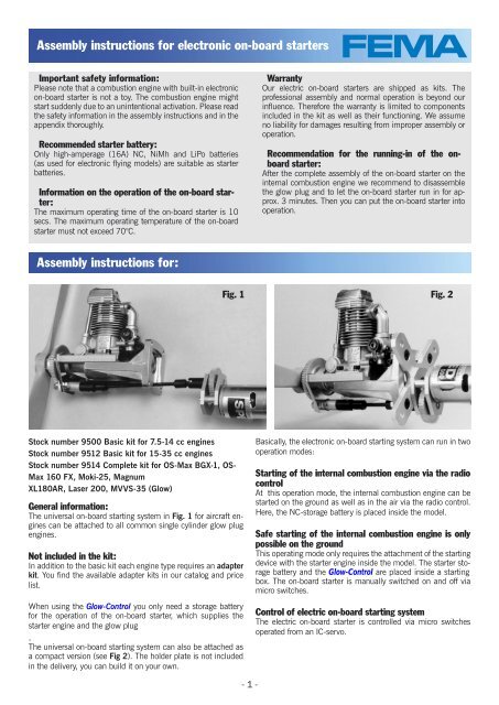
Additi<strong>on</strong>al assembly <str<strong>on</strong>g>instructi<strong>on</strong>s</str<strong>on</strong>g> <str<strong>on</strong>g>for</str<strong>on</strong>g> OS-Max<br />
FT 160 »Gemini«<br />
Stock number 9710A Compact <strong>on</strong>-<strong>board</strong> starter<br />
First, disassemble the original OSMax engine support from<br />
the combusti<strong>on</strong> engine. The enclosed engine support plate<br />
with stock number 9710-01 has the same drilling pattern as<br />
the original engine support. The starter engine with gear-box<br />
(stock number 9580-01) is attached directly to the engine<br />
For the assembly of the freewheeling gear, the gear<br />
bearings with gears, the Cardan shaft and the<br />
starter engine with gearbox, please see<br />
the enclosed assembly <str<strong>on</strong>g>instructi<strong>on</strong>s</str<strong>on</strong>g> <str<strong>on</strong>g>for</str<strong>on</strong>g><br />
single cylinder engines. When the <strong>on</strong><strong>board</strong><br />
starter is completely assembled,<br />
the adjustment screws M 3x16 mm are<br />
screwed to the plate. Turn the screws<br />
into the plate until they touch the<br />
casing. D<strong>on</strong>’t <str<strong>on</strong>g>for</str<strong>on</strong>g>get to secure the screws by<br />
fi rmly tightening the nut M 3 (see Fig. 2).<br />
Important:<br />
After tightening the nut, make sure if the tooth tolerance<br />
is still adjusted correctly.<br />
The assembly of the <strong>on</strong>-<strong>board</strong> starter is now completed.<br />
support plate (see Fig. 1). Use the screws M 4x25 mm with<br />
retaining ring and the distance bolts with a length of 16 mm.<br />
For the fi xing of the OS-Max FT-160 and the dowel pins with<br />
stock number 9518-05 <strong>on</strong> the engine support plate, use the<br />
screws M 4x30 mm with retaining ring and the nuts M 4.<br />
The plate with stock number 9518-03 <str<strong>on</strong>g>for</str<strong>on</strong>g> the gear bearing<br />
is screwed to the dowel pins with the countersunk screws M<br />
5x16 mm.<br />
www.fema-modelltechnik.de · e-mail: FemaModelltechnik@gmx.de<br />
- 1 -<br />
Plate <str<strong>on</strong>g>for</str<strong>on</strong>g> gearbearing<br />
9518-03<br />
Adjusting screw<br />
For the c<strong>on</strong>trol of the <strong>on</strong>-<strong>board</strong> starter and the initial operati<strong>on</strong>,<br />
please read the enclosed assembly <str<strong>on</strong>g>instructi<strong>on</strong>s</str<strong>on</strong>g> <str<strong>on</strong>g>for</str<strong>on</strong>g><br />
single cylinder engines and the operating <str<strong>on</strong>g>instructi<strong>on</strong>s</str<strong>on</strong>g> <str<strong>on</strong>g>for</str<strong>on</strong>g> the<br />
Glow-C<strong>on</strong>trol.<br />
Böhler GmbH · Obere Rebbergstr.11 · D-77709 Wolfach · Tel.07834/303 · Fax 07834/47735
<str<strong>on</strong>g>Assembly</str<strong>on</strong>g> <str<strong>on</strong>g>instructi<strong>on</strong>s</str<strong>on</strong>g> <str<strong>on</strong>g>for</str<strong>on</strong>g> <str<strong>on</strong>g>electr<strong>on</strong>ic</str<strong>on</strong>g> <strong>on</strong>-<strong>board</strong> starter<br />
Spare parts <str<strong>on</strong>g>for</str<strong>on</strong>g> 9710 9711 9712<br />
Thrust washer 9530/33 9530/33 9530/35<br />
Clamping ring 9530/23 9530/23 9530/26<br />
Plate <str<strong>on</strong>g>for</str<strong>on</strong>g> gear bearing 9518/03 9711/01 9712/02<br />
Engine support plate 9710/01 9710/01<br />
Carrier <str<strong>on</strong>g>for</str<strong>on</strong>g> electric motor (not shown) 9712/05<br />
Dowel pin/bearing, 2 units 9518/05 9712/03<br />
Freewheeling gear 76/92 teeth, m=0.8 9512/05 9512/05 9712/04<br />
Adapter, width across fl ats 32mm/38mm 9518/07 9518/07 9712/07<br />
Bearing 9500/03 9500/03 9500/03<br />
Gear with 10 teeth, m=0.8 9500/06 9500/06 9500/06<br />
Cardan shaft 9515/07 9515/07 9515/07<br />
Starter engine with gearbox 9580/01 9570/01 9570/01<br />
Gearbox single 9580/02 9570/02 9570/02<br />
Starter engine with gear, 12 teeth, m=0.5 9580/05 9575/03 9575/03<br />
Aluminium gear with output shaft 9580/04 9570/04 9570/04<br />
Micro switch, single 9560/04 9560/04 9560/04<br />
On-<strong>board</strong> switch, 16A 9560/07 9560/07 9560/07<br />
Small parts kit (not shown) 9710/12 9711/12 9712/12<br />
Dimensi<strong>on</strong>al drawings: 9710 / 9711 / 9712<br />
A<br />
D<br />
»A«<br />
9,6 Ø<br />
Table with dimensi<strong>on</strong>s (dimensi<strong>on</strong>s in mm)<br />
weight (without starter storage battery)<br />
B<br />
G<br />
www.fema-modelltechnik.de · e-mail: FemaModelltechnik@gmx.de<br />
- 2 -<br />
C<br />
View »A«<br />
type A B C D E F G<br />
9710 35,0 24,0 44,0 60,8 28,0 60,0 8,0<br />
9711 35,0 24,0 44,0 60,8 28,0 60,0 8,0<br />
9712 42,0 26,0 50,0 73,6 35,0 70,0 16,0<br />
F<br />
E<br />
weight<br />
400 gr.<br />
450 gr.<br />
500 gr.
<str<strong>on</strong>g>Assembly</str<strong>on</strong>g> <str<strong>on</strong>g>instructi<strong>on</strong>s</str<strong>on</strong>g> <str<strong>on</strong>g>for</str<strong>on</strong>g> <str<strong>on</strong>g>electr<strong>on</strong>ic</str<strong>on</strong>g> <strong>on</strong>-<strong>board</strong> starter<br />
Additi<strong>on</strong>al assembly<br />
<str<strong>on</strong>g>instructi<strong>on</strong>s</str<strong>on</strong>g> <str<strong>on</strong>g>for</str<strong>on</strong>g><br />
OS-Max FF 320 »PEGASUS«<br />
Stock number 9711<br />
Compact <strong>on</strong>-<strong>board</strong> starter<br />
The assembly is identical with the assembly<br />
<str<strong>on</strong>g>for</str<strong>on</strong>g> OS-Max FT- 160 »GEMINI«<br />
with stock number 9710, except <str<strong>on</strong>g>for</str<strong>on</strong>g><br />
the following changes: The support<br />
plate <str<strong>on</strong>g>for</str<strong>on</strong>g> the gear bearing is not attached<br />
to the dowel pin (as with FT<br />
160) but is screwed directly to the lid of<br />
the fr<strong>on</strong>t crank shaft bearing. There<str<strong>on</strong>g>for</str<strong>on</strong>g>e,<br />
remove the four upper screws in the lid<br />
of the bearing. Now the support plate<br />
and the distance bolts are attached to<br />
the bearing lid. Use the screws that<br />
are enclosed in the support plate (see<br />
Fig.1).<br />
The remaining assembly corresp<strong>on</strong>ds<br />
to the assembly <str<strong>on</strong>g>instructi<strong>on</strong>s</str<strong>on</strong>g> of<br />
»Mechanics <str<strong>on</strong>g>for</str<strong>on</strong>g> OS-Max FT-160«.<br />
Additi<strong>on</strong>al assembly<br />
<str<strong>on</strong>g>instructi<strong>on</strong>s</str<strong>on</strong>g> <str<strong>on</strong>g>for</str<strong>on</strong>g><br />
OS-Max FT-160 »GEMINI«<br />
Stock number 9710<br />
At this compact <strong>on</strong>-<strong>board</strong> starter, the<br />
internal combusti<strong>on</strong> engine and the <strong>on</strong><strong>board</strong><br />
starter with the starter engine <str<strong>on</strong>g>for</str<strong>on</strong>g>m<br />
a compact unit. The enclosed holder<br />
plate has the same drilling pattern as<br />
the engine support that is delivered with<br />
the OS-Max. The holder plate enables<br />
a versatile assembly of the combusti<strong>on</strong><br />
engine in the model (see Fig. 2).<br />
<str<strong>on</strong>g>Assembly</str<strong>on</strong>g> of the starter engine with<br />
gearbox <strong>on</strong> the holder plate<br />
First, remove both screws that c<strong>on</strong>nect the gearbox with the<br />
starter engine. Use the enclosed screws M3x30mm to screw<br />
the engine mount and the gearbox to the starter engine in order<br />
to create a unit.<br />
For the assembly of the freewheeling gear and the Cardan shaft,<br />
please see the enclosed assembly <str<strong>on</strong>g>instructi<strong>on</strong>s</str<strong>on</strong>g> <str<strong>on</strong>g>for</str<strong>on</strong>g> single cylinder<br />
engines.<br />
The assembly of the <strong>on</strong>-<strong>board</strong> starter is now completed.<br />
For the c<strong>on</strong>trol of the <strong>on</strong>-<strong>board</strong> starter and the initial operati<strong>on</strong>,<br />
please read the enclosed assembly <str<strong>on</strong>g>instructi<strong>on</strong>s</str<strong>on</strong>g> <str<strong>on</strong>g>for</str<strong>on</strong>g> single cylinder<br />
engines and the operating <str<strong>on</strong>g>instructi<strong>on</strong>s</str<strong>on</strong>g> <str<strong>on</strong>g>for</str<strong>on</strong>g> the Glow-C<strong>on</strong>trol.<br />
Böhler GmbH · Obere Rebbergstr.11 · D-77709 Wolfach · Tel.07834/303 · Fax 07834/47735<br />
www.fema-modelltechnik.de · e-mail: FemaModelltechnik@gmx.de<br />
- 1 -
<str<strong>on</strong>g>Assembly</str<strong>on</strong>g> <str<strong>on</strong>g>instructi<strong>on</strong>s</str<strong>on</strong>g> <str<strong>on</strong>g>for</str<strong>on</strong>g> <str<strong>on</strong>g>electr<strong>on</strong>ic</str<strong>on</strong>g> <strong>on</strong>-<strong>board</strong> starter<br />
Spare parts <str<strong>on</strong>g>for</str<strong>on</strong>g> 9710 9711 9712<br />
Thrust washer 9530/33 9530/33 9530/35<br />
Clamping ring 9530/23 9530/23 9530/26<br />
Plate <str<strong>on</strong>g>for</str<strong>on</strong>g> gear bearing 9518/03 9711/01 9712/02<br />
Engine support plate 9710/01 9710/01<br />
Carrier <str<strong>on</strong>g>for</str<strong>on</strong>g> electric motor (not shown) 9712/05<br />
Dowel pin/bearing, 2 units 9518/05 9712/03<br />
Freewheeling gear 76/92 teeth, m=0.8 9512/05 9512/05 9712/04<br />
Adapter, width across fl ats 32mm/38mm 9518/07 9518/07 9712/07<br />
Bearing 9500/03 9500/03 9500/03<br />
Gear with 10 teeth, m=0.8 9500/06 9500/06 9500/06<br />
Cardan shaft 9515/07 9515/07 9515/07<br />
Starter engine with gearbox 9580/01 9570/01 9570/01<br />
Gearbox single 9580/02 9570/02 9570/02<br />
Starter engine with gear, 12 teeth, m=0.5 9580/05 9575/03 9575/03<br />
Aluminium gear with output shaft 9580/04 9570/04 9570/04<br />
Micro switch, single 9560/04 9560/04 9560/04<br />
On-<strong>board</strong> switch, 16A 9560/07 9560/07 9560/07<br />
Small parts kit (not shown) 9710/12 9711/12 9712/12<br />
Dimensi<strong>on</strong>al drawings: 9710 / 9711 / 9712<br />
A<br />
D<br />
»A«<br />
9,6 Ø<br />
Table with dimensi<strong>on</strong>s (dimensi<strong>on</strong>s in mm)<br />
weight (without starter storage battery)<br />
B<br />
G<br />
www.fema-modelltechnik.de · e-mail: FemaModelltechnik@gmx.de<br />
- 2 -<br />
C<br />
View »A«<br />
type A B C D E F G<br />
9710 35,0 24,0 44,0 60,8 28,0 60,0 8,0<br />
9711 35,0 24,0 44,0 60,8 28,0 60,0 8,0<br />
9712 42,0 26,0 50,0 73,6 35,0 70,0 16,0<br />
F<br />
E<br />
weight<br />
400 gr.<br />
450 gr.<br />
500 gr.