Assembly instructions for electronic on-board starters - FEMA ...
Assembly instructions for electronic on-board starters - FEMA ...
Assembly instructions for electronic on-board starters - FEMA ...

You also want an ePaper? Increase the reach of your titles
YUMPU automatically turns print PDFs into web optimized ePapers that Google loves.
<str<strong>on</strong>g>Assembly</str<strong>on</strong>g> <str<strong>on</strong>g>instructi<strong>on</strong>s</str<strong>on</strong>g> <str<strong>on</strong>g>for</str<strong>on</strong>g> <str<strong>on</strong>g>electr<strong>on</strong>ic</str<strong>on</strong>g> <strong>on</strong>-<strong>board</strong> <strong>starters</strong><br />
For the secure starting of the internal combusti<strong>on</strong> engine it is<br />
necessary that, at the activati<strong>on</strong> of the engine, the starter engine<br />
starts immediately with full power to prevent the kick-back of<br />
the combusti<strong>on</strong> engine. (Please do not use electric c<strong>on</strong>trollers.)<br />
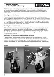
Power supply of the electric <strong>on</strong>-<strong>board</strong> starter<br />
The power supply of the starter engine and of the heater plug<br />
<strong>on</strong>ly requires a storage battery to which also the Glow-C<strong>on</strong>trol<br />
is c<strong>on</strong>nected.<br />
Recommendati<strong>on</strong> <str<strong>on</strong>g>for</str<strong>on</strong>g> starting storage batteries:<br />
9.6 - 12 Volt, min. 1.8 Ah.<br />
Adapters <str<strong>on</strong>g>for</str<strong>on</strong>g> 7.5 - 35 cc aircraft engines<br />
In additi<strong>on</strong> to the basic kit, an adapter is necessary <str<strong>on</strong>g>for</str<strong>on</strong>g><br />
each engine type. Adapters can be combined individually <str<strong>on</strong>g>for</str<strong>on</strong>g><br />
internal combusti<strong>on</strong> engines that are not listed above. Please<br />
specify with your order thread = d1 and diameter = d2.<br />
Available clamping rings and thrust washers:<br />
d2: 6.0; 7.0: 8.0; 9.5; 10; 12 (mm)<br />
Available nuts: d1: M6; M7; M8; 1/4-28UNF,<br />
5/16-24UNF, 3/8-24UNF, M8x1, M10x1<br />
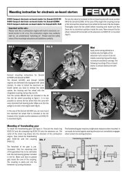
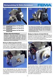
<str<strong>on</strong>g>Assembly</str<strong>on</strong>g> of the support, plate and bearing with gear<br />
When the gearwheel is mounted, the support and the<br />
bearing with gear are attached. (Fig. 4.)<br />
The plate and the attached bearing with gear are<br />
temporarily screwed to both supports with the supports<br />
evenly placed. Then put the combusti<strong>on</strong> engine <strong>on</strong>to the<br />
support so that the gearwheel and gear are exactly <strong>on</strong> top of<br />
each other. Now the fi xing holes <str<strong>on</strong>g>for</str<strong>on</strong>g> the combusti<strong>on</strong> engine<br />
can be drilled into both supports (fi rmly clamp the supports<br />
to the combusti<strong>on</strong> engine). When the combusti<strong>on</strong> engine is<br />
- 2 -<br />
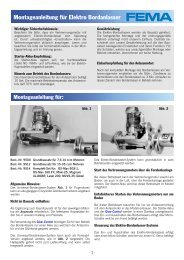
Instructi<strong>on</strong>s <str<strong>on</strong>g>for</str<strong>on</strong>g> the installati<strong>on</strong> of the mechanical<br />
comp<strong>on</strong>ents<br />
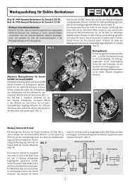
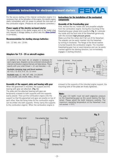
<str<strong>on</strong>g>Assembly</str<strong>on</strong>g> of the freewheeling gear<br />
First, remove the nut, holder disc and propeller adapter<br />
from the combusti<strong>on</strong> engine. During the mounting of the<br />
freewheeling gear please stick exactly to Fig. 3. Lubricate<br />
the inside and the fr<strong>on</strong>t side of the freewheel generously<br />
with the enclosed high pressure grease.<br />
Make sure that the rollers d<strong>on</strong>’t fall out of the freewheel.<br />
The adapter can be easily inserted into the freewheel<br />
by turning it clockwise. The fl ange of the thrust washer<br />
is turned towards the combusti<strong>on</strong> engine. The mounted<br />
freewheeling gear has an axial tolerance and can be easily<br />
cranked against the starting directi<strong>on</strong>, but immediately<br />
engages in starting directi<strong>on</strong>.<br />
holder disclaimer thrust washer<br />
nut clamping ring<br />
screwed to the supports of the intended engine support, the<br />
mounting bolts of the plate are fi nally tightened.<br />
Note:<br />
The gear (10 teeth) must not exert edgewise pressure<br />
<strong>on</strong> the freewheeling gear as this would destroy the freewheel.<br />
Please adjust the tooth tolerance carefully. The<br />
maximum operating temperature at the freewheel must<br />
not exceed +70°C.<br />
Fig. 3