Assembly instructions for electronic on-board starters - FEMA ...
Assembly instructions for electronic on-board starters - FEMA ...
Assembly instructions for electronic on-board starters - FEMA ...

You also want an ePaper? Increase the reach of your titles
YUMPU automatically turns print PDFs into web optimized ePapers that Google loves.
<str<strong>on</strong>g>Assembly</str<strong>on</strong>g> <str<strong>on</strong>g>instructi<strong>on</strong>s</str<strong>on</strong>g> <str<strong>on</strong>g>for</str<strong>on</strong>g> <str<strong>on</strong>g>electr<strong>on</strong>ic</str<strong>on</strong>g> <strong>on</strong>-<strong>board</strong> <strong>starters</strong><br />
C<strong>on</strong>trol of the <str<strong>on</strong>g>electr<strong>on</strong>ic</str<strong>on</strong>g> <strong>on</strong>-<strong>board</strong> starter<br />
General in<str<strong>on</strong>g>for</str<strong>on</strong>g>mati<strong>on</strong><br />
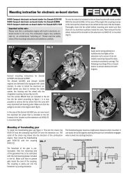
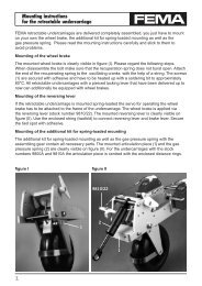
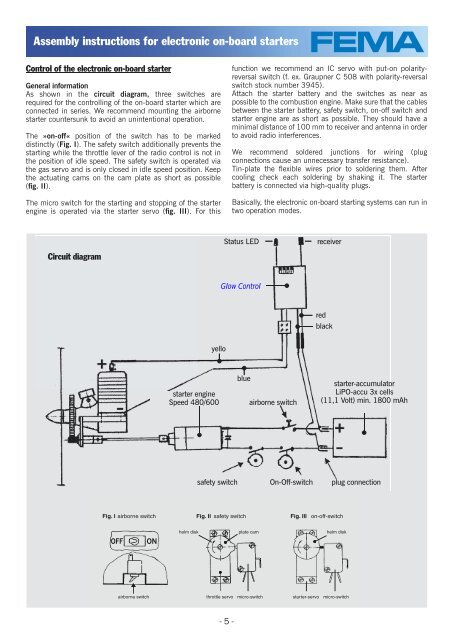
As shown in the circuit diagram, three switches are<br />
required <str<strong>on</strong>g>for</str<strong>on</strong>g> the c<strong>on</strong>trolling of the <strong>on</strong>-<strong>board</strong> starter which are<br />
c<strong>on</strong>nected in series. We recommend mounting the airborne<br />
starter countersunk to avoid an unintenti<strong>on</strong>al operati<strong>on</strong>.<br />
The »<strong>on</strong>-off« positi<strong>on</strong> of the switch has to be marked<br />
distinctly (Fig. I). The safety switch additi<strong>on</strong>ally prevents the<br />
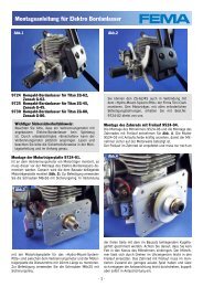
starting while the throttle lever of the radio c<strong>on</strong>trol is not in<br />
the positi<strong>on</strong> of idle speed. The safety switch is operated via<br />
the gas servo and is <strong>on</strong>ly closed in idle speed positi<strong>on</strong>. Keep<br />
the actuating cams <strong>on</strong> the cam plate as short as possible<br />
(fi g. II).<br />
The micro switch <str<strong>on</strong>g>for</str<strong>on</strong>g> the starting and stopping of the starter<br />
engine is operated via the starter servo (fi g. III). For this<br />
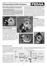
Circuit diagram<br />
airborne switch<br />
yello<br />
starter engine<br />
Speed 480/600<br />
- 5 -<br />
functi<strong>on</strong> we recommend an IC servo with put-<strong>on</strong> polarityreversal<br />
switch (f. ex. Graupner C 508 with polarity-reversal<br />
switch stock number 3945).<br />
Attach the starter battery and the switches as near as<br />
possible to the combusti<strong>on</strong> engine. Make sure that the cables<br />
between the starter battery, safety switch, <strong>on</strong>-off switch and<br />
starter engine are as short as possible. They should have a<br />
minimal distance of 100 mm to receiver and antenna in order<br />
to avoid radio interferences.<br />
We recommend soldered juncti<strong>on</strong>s <str<strong>on</strong>g>for</str<strong>on</strong>g> wiring (plug<br />
c<strong>on</strong>necti<strong>on</strong>s cause an unnecessary transfer resistance).<br />
Tin-plate the fl exible wires prior to soldering them. After<br />
cooling check each soldering by shaking it. The starter<br />
battery is c<strong>on</strong>nected via high-quality plugs.<br />
Basically, the <str<strong>on</strong>g>electr<strong>on</strong>ic</str<strong>on</strong>g> <strong>on</strong>-<strong>board</strong> starting systems can run in<br />
two operati<strong>on</strong> modes.<br />
Status LED receiver<br />
Glow C<strong>on</strong>trol<br />
blue<br />
red<br />
black<br />
starter-accumulator<br />
LiPO-accu 3x cells<br />
(11,1 Volt) min. 1800 mAh<br />
safety switch On-Off-switch plug c<strong>on</strong>necti<strong>on</strong><br />
Fig. I airborne switch Fig. II safety switch Fig. III <strong>on</strong>-off-switch<br />
OFF<br />
ON<br />
helm disk plate cam<br />
helm disk<br />
throttle servo<br />
micro-switch starter-servo micro-switch